

Page 1
EN
Suntracer KNX sl basic
Weather Station
Item number 70156
Installation and Adjustment
Page 2

1 Contents
1. Description ........................................................................................... 4
1.0.1. Deliverables ................................................................................................... 4
1.1. Technical specification ............................................................................................. 5
2. Installation and start-up ....................................................................... 6
2.1. Installation notes ...................................................................................................... 6
2.2. Installation location .................................................................................................. 6
2.3. Device design ........................................................................................................... 8
2.4. Installing the weather station .................................................................................. 9
2.4.1. Preparation for installation .......................................................................... 9
2.4.2. Fitting the lower part with mounting .......................................................... 9
2.4.3. Connection .................................................................................................. 11
2.4.4. Closing the installation ............................................................................... 12
2.5. Instructions for assembly and initial start-up ...................................................... 12
3. Addressing the equipment ................................................................. 13
4. Maintenance ....................................................................................... 13
5. Transfer protocol ............................................................................... 15
5.1. List of all communications objects ....................................................................... 15
6. Parameter setting .............................................................................. 32
6.0.1. Behaviour on power failure/power restoration ........................................ 32
6.0.2. Storage of threshold values ....................................................................... 32
6.0.3. Malfunction objects .................................................................................... 32
6.1. Rain .......................................................................................................................... 32
6.2. Temperature measurement value ........................................................................ 33
6.3. Temperature threshold values .............................................................................. 34
6.3.1. Temperature threshold value 1-4 .............................................................. 34
6.4. Frost alarm .............................................................................................................. 36
6.5. Brightness measurement value ............................................................................ 37
6.6. Brightness threshold values sensor 1-3 and brightness threshold values total 37
6.6.1. Threshold values 1-4 .................................................................................. 38
6.7. Twilight brightness threshold values ................................................................... 40
6.7.1. Twilight threshold value 1-4 ...................................................................... 40
6.8. Night ........................................................................................................................ 42
6.9. Wind measurement ................................................................................................ 43
6.10.Wind threshold values ........................................................................................... 44
6.10.1.Wind threshold value 1-4 ........................................................................... 44
6.11.Computer ................................................................................................................ 46
6.11.1.Computers 1-8 ............................................................................................. 46
6.12.Weekly timer .......................................................................................................... 50
6.12.1.Weekly timer period 1-24 ........................................................................... 50
6.13.Calendar timer ........................................................................................................ 51
6.13.1.Calendar clock Period 1-4 ........................................................................... 52
6.14.Logic ........................................................................................................................ 53
6.14.1.AND logic 1-8 and OR logic outputs 1-8 ................................................... 53
6.14.2.AND logic connection inputs ..................................................................... 55
Weather Station Suntracer KNX sl basic • from software version 1.00, ETS programme version 1.0
Elsner Elektronik GmbH • Sohlengrund 16 • 75395 Ostelsheim • Germany
Status: 11.03.2016 • Errors excepted. Subject to technical changes.
Page 3

2 Contents
6.14.3.Connection inputs of the OR logic ............................................................. 59
Weather Station Suntracer KNX sl basic • from software version 1.00, ETS programme version 1.0
Elsner Elektronik GmbH • Sohlengrund 16 • 75395 Ostelsheim • Germany
Status: 11.03.2016 • Errors excepted. Subject to technical changes.
Page 4
3 Clarification of signs
Installation, inspection, commissioning and troubleshooting of the device
must only be carried out by a competent electrician.
This manual is amended periodically and will be brought into line with new software
releases. The change status (software version and date) can be found in the contents footer.
If you have a device with a later software version, please check
www.elsner-elektronik.de in the menu area "Service" to find out whether a more up-todate version of the manual is available.
Clarification of signs used in this manual
Safety advice.
Safety advice for working on electrical connections, components,
etc.
DANGER!
WARNING!
CAUTION!
ATTENTION!
ETS In the ETS tables, the parameter default settings are marked by
... indicates an immediately hazardous situation which will lead to
death or severe injuries if it is not avoided.
... indicates a potentially hazardous situation which may lead to
death or severe injuries if it is not avoided.
... indicates a potentially hazardous situation which may lead to
trivial or minor injuries if it is not avoided.
... indicates a situation which may lead to damage to property if it is
not avoided.
underlining.
Page 5

4
1. Description
The Weather Station Suntracer KNX sl basic for the KNX building bus system
measures temperature, wind speed, brightness and recognises precipitation. All values can be used for the control of limit dependent switching outputs. States can be linked via AND logic gates and OR logic gates. Multi-function modules change input data
as required by means of calculations, querying a condition, or converting the data
point type.
The compact housing of the Suntracer KNX sl basic accommodates the sensors,
evaluation circuits and bus-coupling electronics.
Functions:
• Brightness measurement (current light strength) with 3 sensors. Separate
values, maximum or mixed value usable
• Wind measurement: The wind strength is measured electronically and thus
noiselessly and reliably, even during hail, snow and sub-zero temperatures.
Even turbulent air and rising winds in the vicinity of the device are recorded
• Precipitation detection: The sensor surface is heated, so that only drops and
flakes are recognised as precipitation, but not mist or dew. When the rain or
snow stops, the sensor is soon dry again and the precipitation warning ends
• Temperature measurement
• Frost protection for shading systems
• Switching outputs for all measured and computed values. Threshold values
can be adjusted per parameter or via communication objects
• 8 AND and 8 OR logic gates, each with 4 inputs. All switching events as well
as 16 logic inputs (in the form of communications objects) can be used as
inputs for the logic gates. The output of each gate can be configured optionally
as 1-bit or 2 x 8-bit
• 8 multi-function modules (computers) for changing the input data by
calculations, by querying a condition or by converting the data point type
Configuration is made using the KNX software ETS. The product file can be downloaded from the Elsner Elektronik homepage on www.elsner-elektronik.de in the “Service” menu.
1.0.1. Deliverables
• Weather station
• Stainless steel installation band for pole installation
• 4×50 mm stainless steel roundhead screws and 6×30 mm dowels for wall
mounting. Use fixing materials that are suitable for the base!
• Size 6 Torx bit
Weather Station Suntracer KNX sl basic • Stand: 11.03.2016 • Technische Änderungen und Irrtümer vorbehalten.
Page 6

5
1.1. Technical specification
Housing Plastic
Colour White / Translucent
Assembly Surface mount
Protection category IP 44
Dimensions approx. 62 × 71 × 145 (W × H × D, mm)
Weight approx. 85 g
Ambient temperature Operation -30…+50°C, storage -30…+70°C
Auxiliary supply 12…40 V DC, 12…28 V AC. An appropriate power sup-
Auxiliary current at 12V DC: max. 185 mA
Bus current max. 10 mA
Data output KNX +/BCU type Integrated microcontroller
PEI type 0
Group addresses max. 2000
Assignments max. 2000
Communication objects 341
Temperature sensor:
Measurement range -30°C … +50°C
Resolution 0.1°C
Accuracy ±0.5°C at -30°C … +25°C
Wind sensor:
Measurement range 0 m/s … 35 m/s
Resolution 0.1 m/s
Accuracy ±15% of the measurement value when incoming flow
Brightness sensor:
Measurement range 0 lux … 150,000 lux
Resolution 1 lux at 0…255 lux
Accuracy ±15% of the measurement value at 35 lux … 150,000
ply unit can be purchased from Elsner Elektronik.
at 24V DC: max. 90 mA
at 24V AC: max. 82 mA
±1.5°C at -30°C … +45°C
is 45°…315°
(Frontal incoming flow corresponds to 180°)
4 lux at 256…2,645 lux
163 lux at 2,646…128,256 lux
762 lux at 128,257…150,000 lux
lux
The product conforms with the provisions of EU directives.
Weather Station Suntracer KNX sl basic • Stand: 11.03.2016 • Technische Änderungen und Irrtümer vorbehalten.
Page 7

6
2. Installation and start-up
2.1. Installation notes
Installation, testing, operational start-up and troubleshooting should
only be performed by an electrician.
CAUTION!
Live voltage!
There are unprotected live components inside the device.
• National legal regulations are to be followed.
• Ensure that all lines to be assembled are free of voltage and take
precautions against accidental switching on.
• Do not use the device if it is damaged.
• Take the device or system out of service and secure it against
unintentional use, if it can be assumed, that risk-free operation is no
longer guaranteed.
The device is only to be used for its intended purpose. Any improper modification or
failure to follow the operating instructions voids any and all warranty and guarantee
claims.
After unpacking the device, check it immediately for possible mechanical damage. If it
has been damaged in transport, inform the supplier immediately.
The device may only be used as a fixed-site installation; that means only when assembled and after conclusion of all installation and operational start-up tasks and only in
the surroundings designated for it.
Elsner Elektronik is not liable for any changes in norms and standards which may occur
after publication of these operating instructions.
2.2. Installation location
Select an installation position on the building where the sensors can measure wind,
rain and sunshine without hindrance. No structural elements should be mounted above the weather station, from which water could continue to drop on the precipitation
sensor even after it has stopped raining or snowing. The weather station should not be
shaded by structures or, for example, trees.
At least 60 cm of clearance must be left around the device. This facilitates correct wind
speed measurement without eddies. At the same time, this prevents spray (raindrops
hitting the device) or snow (snow penetration) from impairing the measurement. This
also prevents birds from biting it.
Please ensure that the extended awning does not cast shade on the unit, and that it is
protected from the wind.
Weather Station Suntracer KNX sl basic • Stand: 11.03.2016 • Technische Änderungen und Irrtümer vorbehalten.
Page 8
7
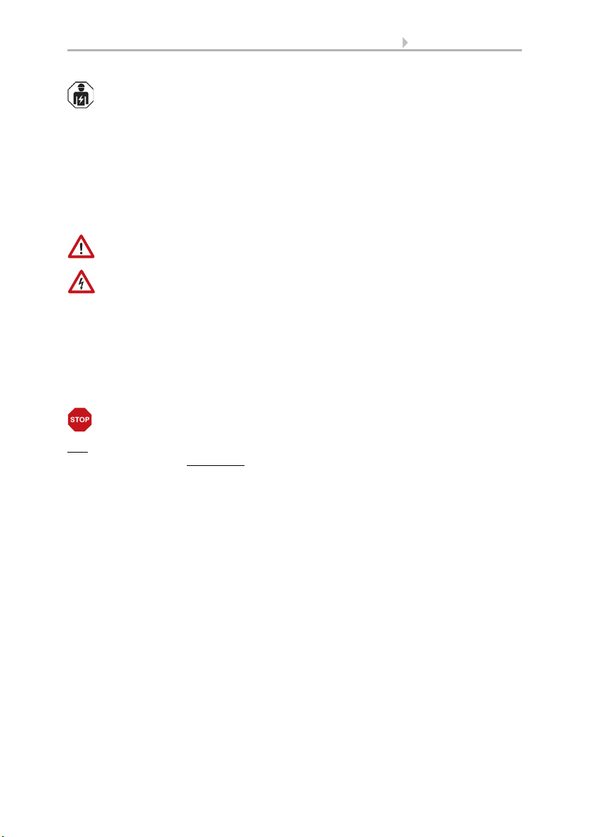
Abb. 1
There must be at least 60 cm clearance to
other elements (structures, construction
parts, etc.) below, to the sides and in front of
the weather station.
60 cm
Abb. 2
The weather station must be attached to a
vertical wall (or a pole).
wall
or
pole
90°
Abb. 3
The weather station must be mounted in the
horizontal (transverse) direction.
Horizontal
Temperature measurements can also be distorted by external influences such as warming or cooling of the building structure on which the sensor is mounted (sunlight, heating or cold water pipes). Temperature variations from such sources of interference
must be corrected in the ETS in order to ensure the specified accuracy of the sensor
(temperature offset).
Weather Station Suntracer KNX sl basic • Stand: 11.03.2016 • Technische Änderungen und Irrtümer vorbehalten.
Page 9
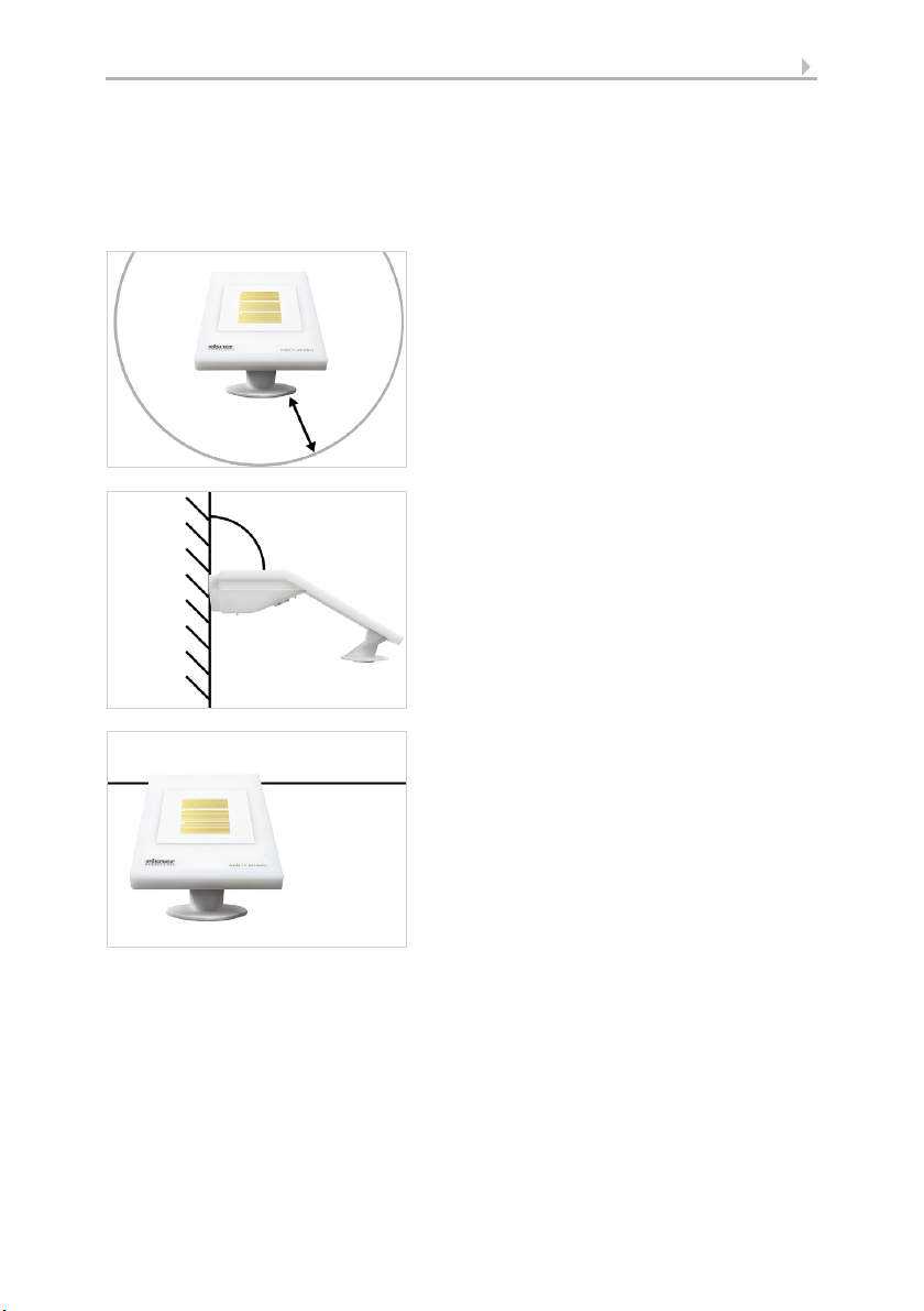
2.3. Device design
Abb. 4
The weather station must be aligned in the direction of the façade which is to be shaded.
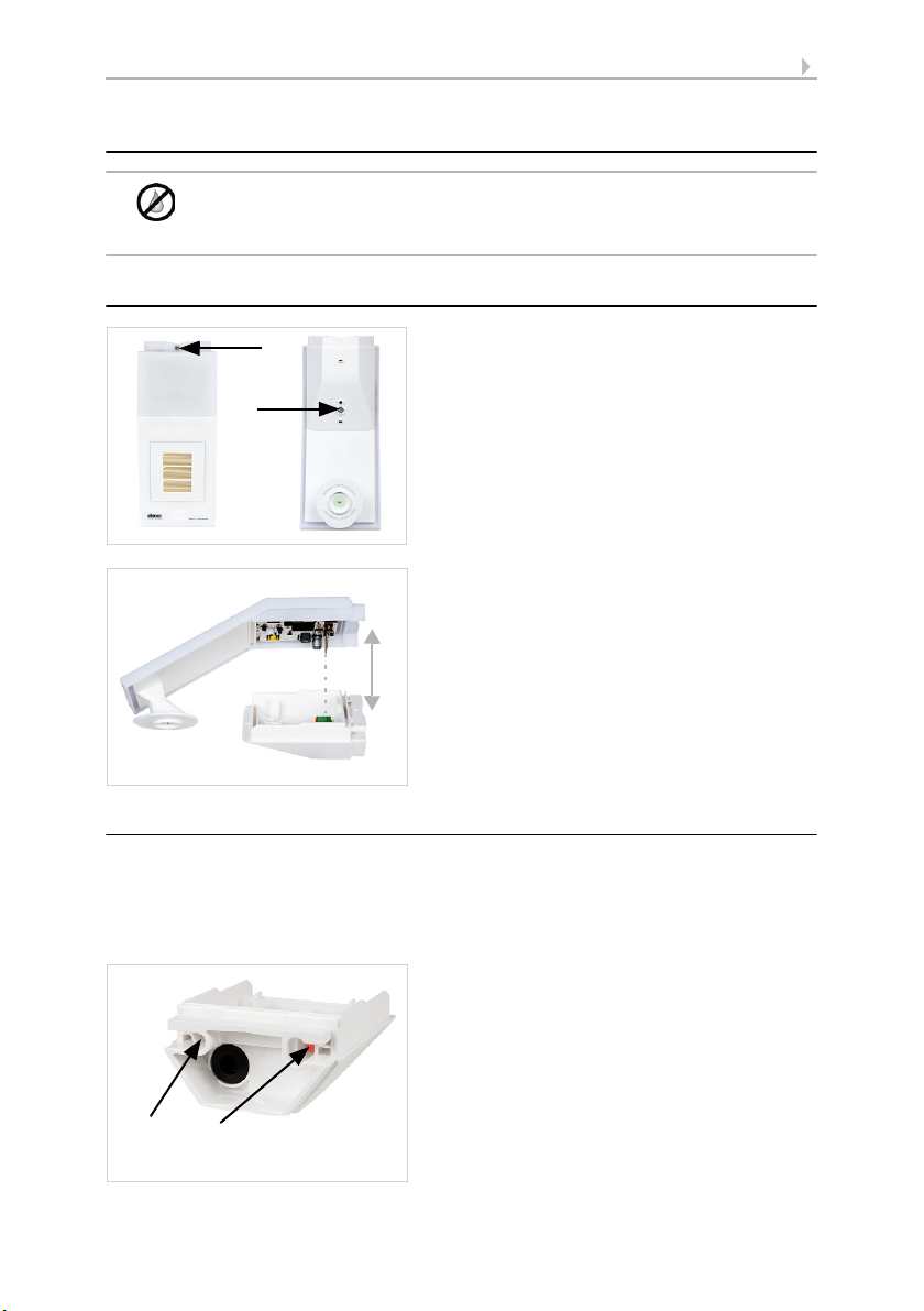
Abb. 5
1 Programming LED
2a, b, c Brightness measurement
3 Precipitation sensor in lid
4 Temperature measurement
5 Wind measurement
6 Programming key on the underside of the housing (recessed),see Addressing the
equipment, page 13
ATTENTION!
Sensitive wind sensor.
• Remove the protective transport sticker after installation.
• Do not touch the sensor on the wind measuring element (no. 5).
4
5
1
2a
3
6
2b
2c
8
Weather Station Suntracer KNX sl basic • Stand: 11.03.2016 • Technische Änderungen und Irrtümer vorbehalten.
Page 10
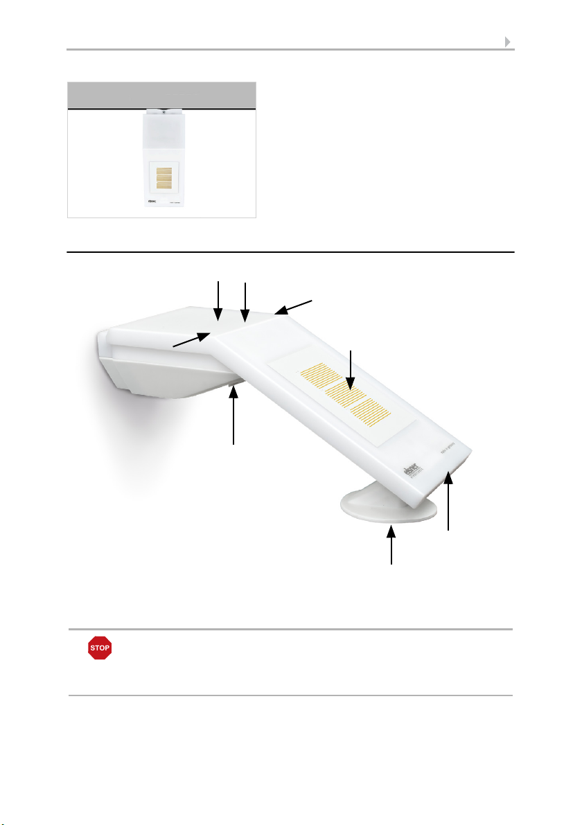
9
Abb. 6
Slacken both screws on the lid (top) and lower part (bottom) with a size 6 Torx screwdriver.
Abb. 7
Pull the lid and lower part completely apart.
This also releases the plug-in connection between the board in the lid and the socket in the
lower part.
Abb. 8
The device is installed with two screws. Break
off the two longitudinal holes in the lower
part of the housing.
Longitudinal holes
2.4. Installing the weather station
ATTENTION!
Even a few drops of water can damage the device electronics.
• Do not open the device if water (e.g. rain) can get into it.
2.4.1. Preparation for installation
2.4.2. Fitting the lower part with mounting
Now, first of all, assemble the lower part of the housing with the integrated mounting
for wall or pole installation.
Wall installation
Use fixing materials (dowels, screws) that are suitable for the base.
Weather Station Suntracer KNX sl basic • Stand: 11.03.2016 • Technische Änderungen und Irrtümer vorbehalten.
Page 11
10
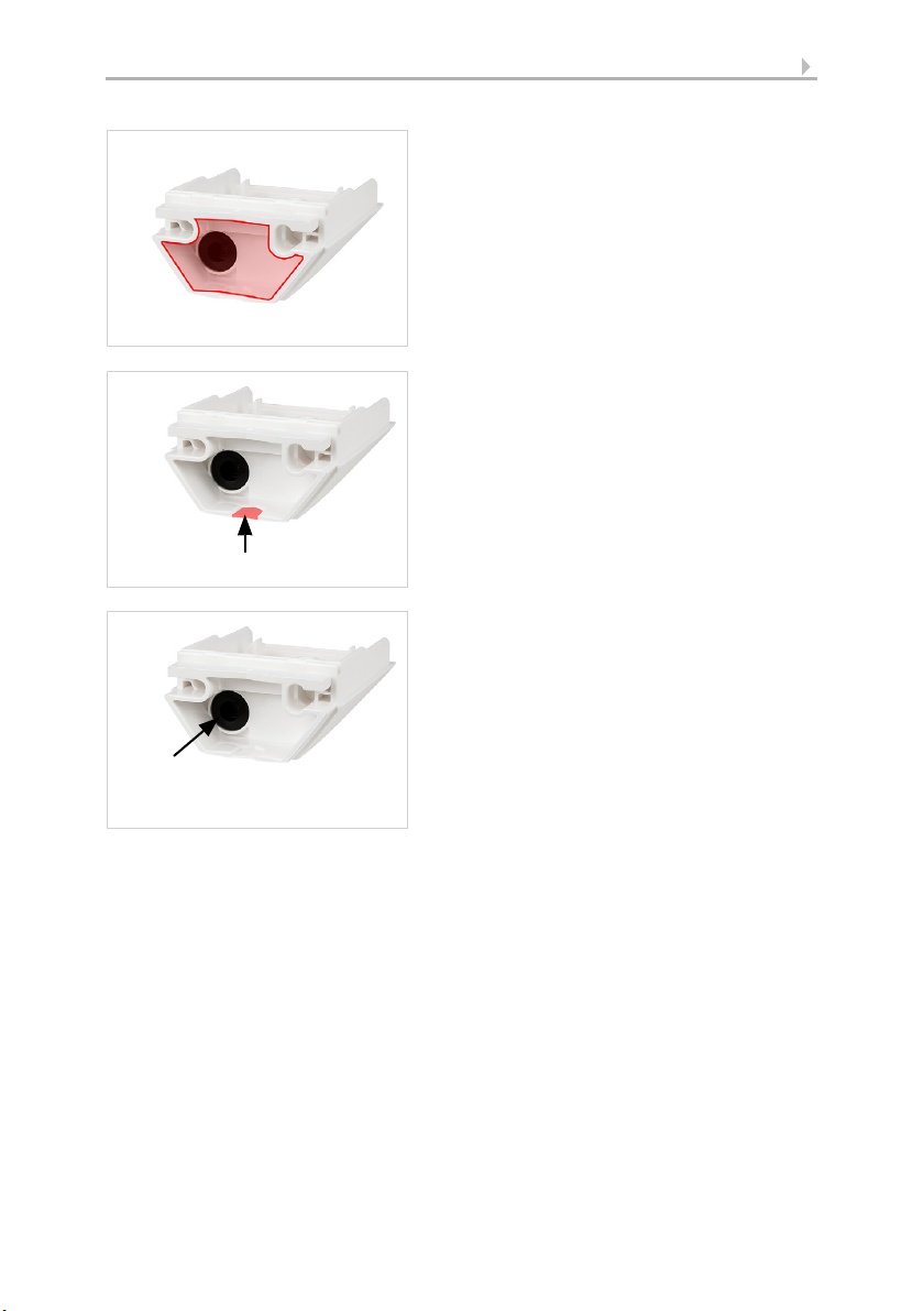
Abb. 9 a+b
a) If the power lead is to be hidden when in-
stalled, it must emerge from the wall in
the vicinity of the rear of the housing
(marked area).
b) If the power lead is to be surface-moun-
ted, the cable guide is broken off. The
lead is then fed into the device at the underside of the housing.
Cable guide
Abb. 10
Feed the power lead through the rubber gasket.
Rubber
gasket
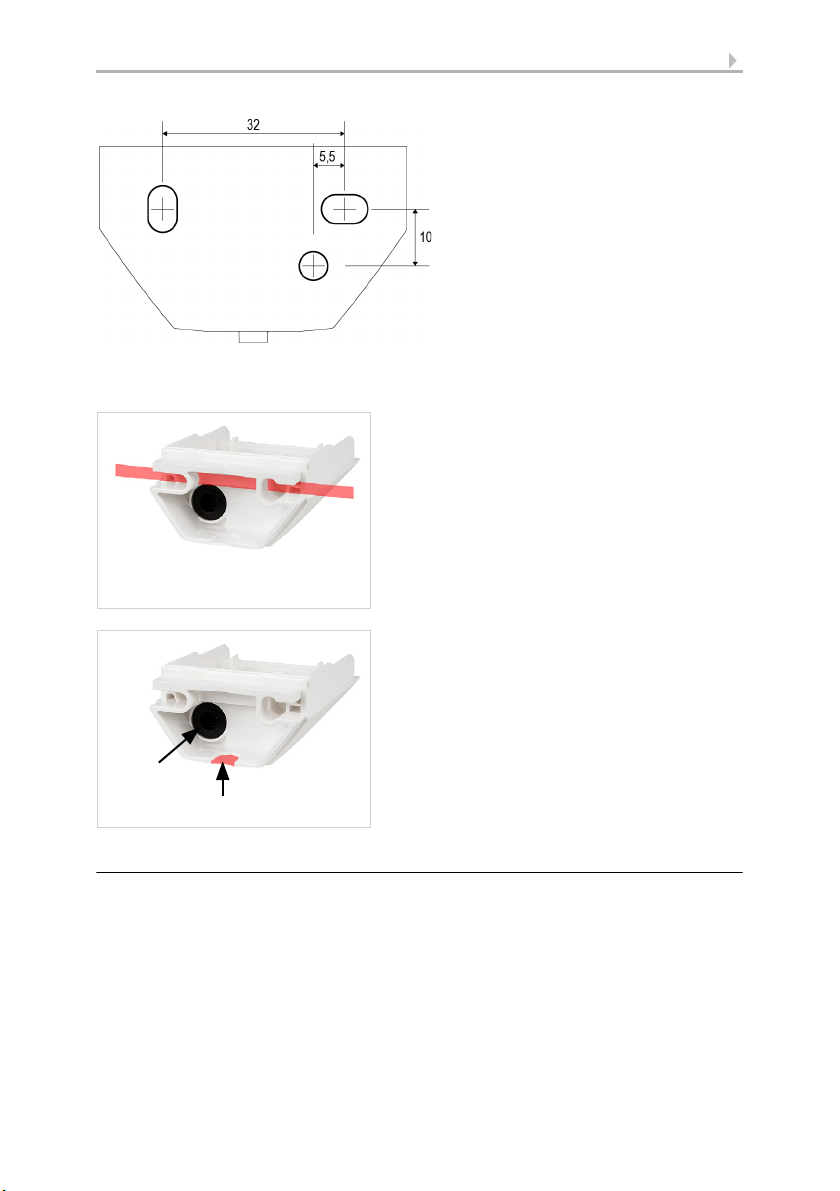
Drilling plan
ATTENTION! The printout of the data sheet does not have original size! A separate, dimensionally correct drilling plan is included ex works and this can be used as a template.
Weather Station Suntracer KNX sl basic • Stand: 11.03.2016 • Technische Änderungen und Irrtümer vorbehalten.
Page 12
11
Abb. 11
Dimensions in mm. Variations are
possible for technical reasons
A/B2× longitudinal holes 8 mm ×
5.5 mm
C Position of the cable outlet (rub-
ber gasket) in the housing
AB
C
Abb. 12
Feed the mounting band through the eyelets
in the lower part of the housing.
Abb. 13
Break the cable guide off.
Feed the power lead through the rubber gasket.
Cable guide
Rubber
gasket
Pole installation
The device is installed on the pole with the enclosed stainless steel mounting band.
2.4.3. Connection
The connector is in the lower part of the housing.
Weather Station Suntracer KNX sl basic • Stand: 11.03.2016 • Technische Änderungen und Irrtümer vorbehalten.
Page 13
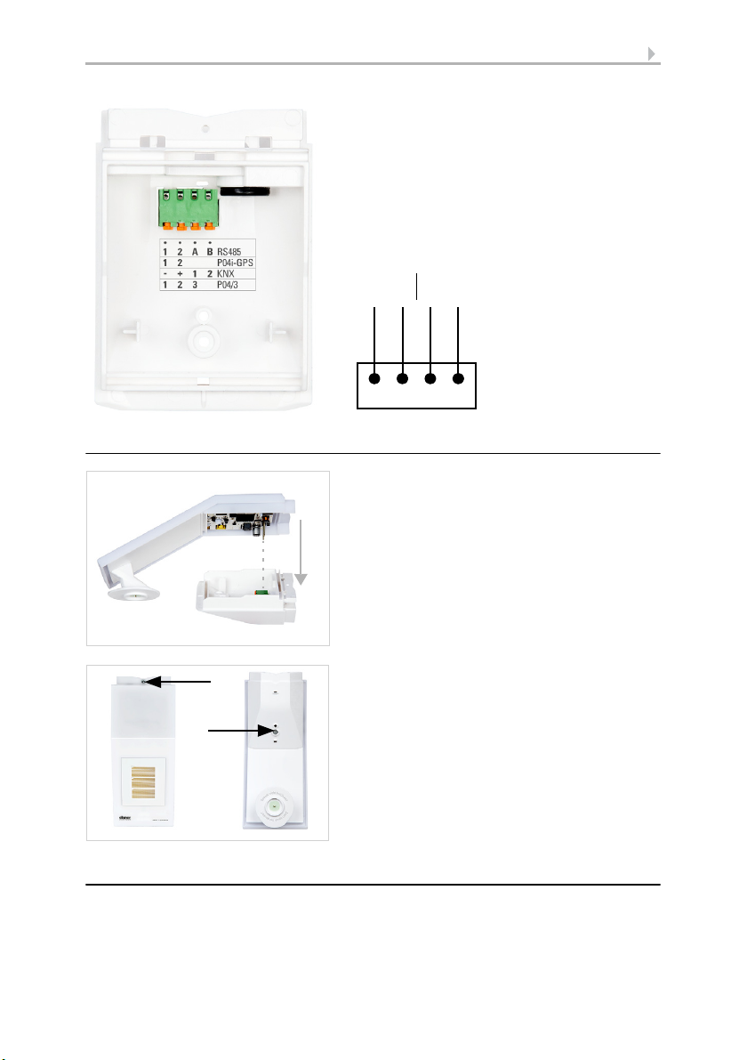
2.4.4. Closing the installation
Abb. 14
Connect
KNX data (+|-) and
power supply (12…40V DC, 12…28V AC, 1|2)
to the connector.
The terminal assignment of the power supply
is polarity-independent.
-+12
-+12
KNX Voltage
Abb. 15
Push the lid on the lower part. This also makes the plug-in connection between the board
in the lid and the socket in the lower part.
Abb. 16
Screw the lid (top) and lower part (bottom) together.
12
2.5. Instructions for assembly and initial start-up
Remove all transport protection stickers present after installation.
The wind measurement value and thus also all wind switching outputs cannot be output until 35 seconds after the power is turned on.
Weather Station Suntracer KNX sl basic • Stand: 11.03.2016 • Technische Änderungen und Irrtümer vorbehalten.
Page 14
13
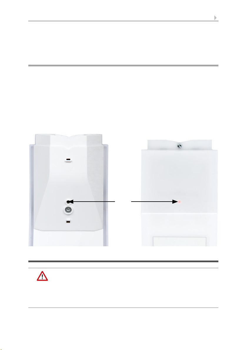
1 2
Abb. 17
1 Programming button for teaching the device
2 Programming LED (under the semi-transparent lid)
After the auxiliary voltage has been applied, the device will enter an initialisation phase
lasting a few seconds. During this phase no information can be received or sent via the
bus.
3. Addressing the equipment
The equipment is delivered ex works with the bus address 15.15.250. You program a
different address in the ETS by overwriting the address 15.15.250 or teach the device
using the programming button.
The programming button can be reached through the opening on the underside of the
housing; it is recessed by approx. 15 mm. Use a thin object to reach the key, e. g. a
1.5 mm² wire.
4. Maintenance
WARNING!
Risk of injury caused by components moved automatically!
The automatic control can start system components and place people in
danger (e.g. moving windows/awnings if a rain/wind alarm has been
triggered while cleaning).
• Always isolate the device from the mains for servicing and cleaning.
Weather Station Suntracer KNX sl basic • Stand: 11.03.2016 • Technische Änderungen und Irrtümer vorbehalten.
Page 15

14
The device must regularly be checked for dirt twice a year and cleaned if necessary. In
case of severe dirt, the sensor may not work properly anymore.
ATTENTION
The device can be damaged if water penetrates the housing.
• Do not clean with high pressure cleaners or steam jets.
Weather Station Suntracer KNX sl basic • Stand: 11.03.2016 • Technische Änderungen und Irrtümer vorbehalten.
Page 16

15 Transfer protocol
5. Transfer protocol
Units:
Temperatures in degrees Celsius
Brightness in Lux
Wind in metres per second
Air pressure in Pascal
Azimuth and elevation in degrees
5.1. List of all communications objects
Abbreviation flags:
C Communication
R Read
WWrite
T Transmit
UUpdate
No. Text Function Flags DPT type Size
1 Software version Output R-CT [217.1] DPT_Version 2 bytes
21 Signal LED object 1s cycle Input -WC- [1.1] DPT_Switch 1 bit
22 Signal LED object 4s cycle Input -WC- [1.1] DPT_Switch 1 bit
34 Rain: Switching output Output R-CT [1.1] DPT_Switch 1 bit
35 Rain: Switching output with fixed
delays
36 Rain: Switching delay to rain Input -WC- [7,005] DPT_TimePeri-
37 Rain: Switching delay to no rain Input -WC- [7,005] DPT_TimePeri-
41 Temperature sensor: Malfunction Output R-CT [1.1] DPT_Switch 1 bit
42 Temperature sensor: External meas-
urement
43 Temperature sensor: Measurement
value
44 Temperature sensor: Total measure-
ment
45 Temperature sensor: Min./Max. meas-
urement query
46 Temperature sensor: Minimum meas-
urement
47 Temperature sensor: Maximum meas-
urement
48 Temperature sensor: Min./Max. meas-
urement reset
51 Temp. threshold value 1: Absolute
value
52 Temp. threshold value 1: (1:+ | 0:-) Input -WC- [1.1] DPT_Switch 1 bit
Output R-CT [1.1] DPT_Switch 1 bit
odSec
odSec
Input -SKÜ [9.1] DPT_Value_Temp 2 bytes
Output R-CT [9.1] DPT_Value_Temp 2 bytes
Output R-CT [9.1] DPT_Value_Temp 2 bytes
Input -WC- [1.017] DPT_Trigger 1 bit
Output R-CT [9.1] DPT_Value_Temp 2 bytes
Output R-CT [9.1] DPT_Value_Temp 2 bytes
Input -WC- [1.017] DPT_Trigger 1 bit
Input/
Output
RWCT [9.1] DPT_Value_Temp 2 bytes
2 bytes
2 bytes
Weather Station Suntracer KNX sl basic • Version: 11.03.2016 • Technical changes and errors excepted.
Page 17

16 Transfer protocol
No. Text Function Flags DPT type Size
53 Temp. threshold value 1: Switching
delay from 0 to 1
54 Temp. threshold value 1: Switching
delay from 1 to 0
55 Temp. threshold value 1: Switching
output
56 Temp. threshold value 1: Switching
output block
58 Temp. threshold value 2: Absolute
value
Input -WC- [7.5] DPT_TimePeriod-
Sec
Input -WC- [7.5] DPT_TimePeriod-
2 bytes
2 bytes
Sec
Output R-CT [1.1] DPT_Switch 1 bit
Input -WC- [1.1] DPT_Switch 1 bit
Input/
RWCT [9.1] DPT_Value_Temp 2 bytes
Output
59 Temp. threshold value 2: (1:+ | 0:-) Input -WC- [1.1] DPT_Switch 1 bit
60 Temp. threshold value 2: Switching
delay from 0 to 1
61 Temp. threshold value 2: Switching
delay from 1 to 0
62 Temp. threshold value 2: Switching
output
63 Temp. threshold value 2: Switching
Input -WC- [7.5] DPT_TimePeriod-
2 bytes
Sec
Input -WC- [7.5] DPT_TimePeriod-
Sec
2 bytes
Output R-CT [1.1] DPT_Switch 1 bit
Input -WC- [1.1] DPT_Switch 1 bit
output block
65 Temp. threshold value 3: Absolute
value
Input/
Output
RWCT [9.1] DPT_Value_Temp 2 bytes
66 Temp. threshold value 3: (1:+ | 0:-) Input -WC- [1.1] DPT_Switch 1 bit
67 Temp. threshold value 3: Switching
delay from 0 to 1
68 Temp. threshold value 3: Switching
delay from 1 to 0
69 Temp. threshold value 3: Switching
output
70 Temp. threshold value 3: Switching
Input -WC- [7.5] DPT_TimePeriod-
2 bytes
Sec
Input -WC- [7.5] DPT_TimePeriod-
Sec
2 bytes
Output R-CT [1.1] DPT_Switch 1 bit
Input -WC- [1.1] DPT_Switch 1 bit
output block
72 Temp. threshold value 4: Absolute
value
Input/
Output
RWCT [9.1] DPT_Value_Temp 2 bytes
73 Temp. threshold value 4: (1:+ | 0:-) Input -WC- [1.1] DPT_Switch 1 bit
74 Temp. threshold value 4: Switching
delay from 0 to 1
75 Temp. threshold value 4: Switching
delay from 1 to 0
76 Temp. threshold value 4: Switching
Input -WC- [7.5] DPT_TimePeriod-
Input -WC- [7.5] DPT_TimePeriod-
Sec
Sec
2 bytes
2 bytes
Output R-CT [1.1] DPT_Switch 1 bit
output
77 Temp. threshold value 4: Switching
output block
Input -WC- [1.1] DPT_Switch 1 bit
81 Frost alarm Output R-CT [1.1] DPT_Switch 1 bit
95 Brightness sensor measurement Output R-CT [9.4] DPT_Value_Lux 2 bytes
96 Brightness sensor 2 measurement Output R-CT [9.4] DPT_Value_Lux 2 bytes
97 Brightness sensor 3 measurement Output R-CT [9.4] DPT_Value_Lux 2 bytes
98 Total brightness measurement Output R-CT [9.4] DPT_Value_Lux 2 bytes
101 Brightness sensor threshold value 1:
Absolute value
Input/
Output
RWCT [9.4] DPT_Value_Lux 2 bytes
Weather Station Suntracer KNX sl basic • Version: 11.03.2016 • Technical changes and errors excepted.
Page 18

17 Transfer protocol
No. Text Function Flags DPT type Size
102 Brightness sensor threshold value 1:
(1:+ | 0:-)
103 Brightness sensor threshold value 1:
Delay from 0 to 1
104 Brightness sensor threshold value 1:
Delay from 1 to 0
105 Brightness sensor threshold value 1:
Switching output
106 Brightness sensor threshold value 1:
Input -WC- [1.1] DPT_Switch 1 bit
Input -WC- [7.5] DPT_TimePeriod-
2 bytes
Sec
Input -WC- [7.5] DPT_TimePeriod-
Sec
2 bytes
Output R-CT [1.1] DPT_Switch 1 bit
Input -WC- [1.1] DPT_Switch 1 bit
Switching output block
108 Brightness sensor threshold value 2:
Absolute value
109 Brightness sensor threshold value 2:
(1:+ | 0:-)
110 Brightness sensor threshold value 2:
Delay from 0 to 1
111 Brightness sensor threshold value 2:
Delay from 1 to 0
112 Brightness sensor threshold value 2:
Switching output
113 Brightness sensor threshold value 2:
Switching output block
115 Brightness sensor threshold value 3:
Absolute value
116 Brightness sensor threshold value 3:
(1:+ | 0:-)
117 Brightness sensor threshold value 3:
Delay from 0 to 1
118 Brightness sensor threshold value 3:
Delay from 1 to 0
119 Brightness sensor threshold value 3:
Switching output
120 Brightness sensor threshold value 3:
Switching output block
122 Brightness sensor threshold value 4:
Absolute value
123 Brightness sensor threshold value 4:
(1:+ | 0:-)
124 Brightness sensor threshold value 4:
Delay from 0 to 1
125 Brightness sensor threshold value 4:
Delay from 1 to 0
126 Brightness sensor threshold value 4:
Switching output
127 Brightness sensor threshold value 4:
Switching output block
129 Brightness sensor 2 threshold value 1:
Absolute value
Input/
Output
RWCT [9.4] DPT_Value_Lux 2 bytes
Input -WC- [1.1] DPT_Switch 1 bit
Input -WC- [7.5] DPT_TimePeriod-
2 bytes
Sec
Input -WC- [7.5] DPT_TimePeriod-
Sec
2 bytes
Output R-CT [1.1] DPT_Switch 1 bit
Input -WC- [1.1] DPT_Switch 1 bit
Input/
RWCT [9.4] DPT_Value_Lux 2 bytes
Output
Input -WC- [1.1] DPT_Switch 1 bit
Input -WC- [7.5] DPT_TimePeriod-
Sec
Input -WC- [7.5] DPT_TimePeriod-
2 bytes
2 bytes
Sec
Output R-CT [1.1] DPT_Switch 1 bit
Input -WC- [1.1] DPT_Switch 1 bit
Input/
RWCT [9.4] DPT_Value_Lux 2 bytes
Output
Input -WC- [1.1] DPT_Switch 1 bit
Input -WC- [7.5] DPT_TimePeriod-
Sec
Input -WC- [7.5] DPT_TimePeriod-
2 bytes
2 bytes
Sec
Output R-CT [1.1] DPT_Switch 1 bit
Input -WC- [1.1] DPT_Switch 1 bit
Input/
RWCT [9.4] DPT_Value_Lux 2 bytes
Output
Weather Station Suntracer KNX sl basic • Version: 11.03.2016 • Technical changes and errors excepted.
Page 19

18 Transfer protocol
No. Text Function Flags DPT type Size
130 Brightness sensor 2 threshold value 1:
(1:+ | 0:-)
131 Brightness sensor 2 threshold value 1:
Delay from 0 to 1
132 Brightness sensor 2 threshold value 1:
Delay from 1 to 0
133 Brightness sensor 2 threshold value 1:
Switching output
134 Brightness sensor 2 threshold value 1:
Input -WC- [1.1] DPT_Switch 1 bit
Input -WC- [7.5] DPT_TimePeriod-
2 bytes
Sec
Input -WC- [7.5] DPT_TimePeriod-
Sec
2 bytes
Output R-CT [1.1] DPT_Switch 1 bit
Input -WC- [1.1] DPT_Switch 1 bit
Switching output block
136 Brightness sensor 2 threshold value 2:
Absolute value
137 Brightness sensor 2 threshold value 2:
(1:+ | 0:-)
138 Brightness sensor 2 threshold value 2:
Delay from 0 to 1
139 Brightness sensor 2 threshold value 2:
Delay from 1 to 0
140 Brightness sensor 2 threshold value 2:
Switching output
141 Brightness sensor 2 threshold value 2:
Switching output block
143 Brightness sensor 2 threshold value 3:
Absolute value
144 Brightness sensor 2 threshold value 3:
(1:+ | 0:-)
145 Brightness sensor 2 threshold value 3:
Delay from 0 to 1
146 Brightness sensor 2 threshold value 3:
Delay from 1 to 0
147 Brightness sensor 2 threshold value 3:
Switching output
148 Brightness sensor 2 threshold value 3:
Switching output block
150 Brightness sensor 2 threshold value 4:
Absolute value
151 Brightness sensor 2 threshold value 4:
(1:+ | 0:-)
152 Brightness sensor 2 threshold value 4:
Delay from 0 to 1
153 Brightness sensor 2 threshold value 4:
Delay from 1 to 0
154 Brightness sensor 2 threshold value 4:
Switching output
155 Brightness sensor 2 threshold value 4:
Switching output block
157 Brightness sensor 3 threshold value 1:
Absolute value
Input/
Output
RWCT [9.4] DPT_Value_Lux 2 bytes
Input -WC- [1.1] DPT_Switch 1 bit
Input -WC- [7.5] DPT_TimePeriod-
2 bytes
Sec
Input -WC- [7.5] DPT_TimePeriod-
Sec
2 bytes
Output R-CT [1.1] DPT_Switch 1 bit
Input -WC- [1.1] DPT_Switch 1 bit
Input/
RWCT [9.4] DPT_Value_Lux 2 bytes
Output
Input -WC- [1.1] DPT_Switch 1 bit
Input -WC- [7.5] DPT_TimePeriod-
Sec
Input -WC- [7.5] DPT_TimePeriod-
2 bytes
2 bytes
Sec
Output R-CT [1.1] DPT_Switch 1 bit
Input -WC- [1.1] DPT_Switch 1 bit
Input/
RWCT [9.4] DPT_Value_Lux 2 bytes
Output
Input -WC- [1.1] DPT_Switch 1 bit
Input -WC- [7.5] DPT_TimePeriod-
Sec
Input -WC- [7.5] DPT_TimePeriod-
2 bytes
2 bytes
Sec
Output R-CT [1.1] DPT_Switch 1 bit
Input -WC- [1.1] DPT_Switch 1 bit
Input/
RWCT [9.4] DPT_Value_Lux 2 bytes
Output
Weather Station Suntracer KNX sl basic • Version: 11.03.2016 • Technical changes and errors excepted.
Page 20

19 Transfer protocol
No. Text Function Flags DPT type Size
158 Brightness sensor 3 threshold value 1:
(1:+ | 0:-)
159 Brightness sensor 3 threshold value 1:
Delay from 0 to 1
160 Brightness sensor 3 threshold value 1:
Delay from 1 to 0
161 Brightness sensor 3 threshold value 1:
Switching output
162 Brightness sensor 3 threshold value 1:
Input -WC- [1.1] DPT_Switch 1 bit
Input -WC- [7.5] DPT_TimePeriod-
2 bytes
Sec
Input -WC- [7.5] DPT_TimePeriod-
Sec
2 bytes
Output R-CT [1.1] DPT_Switch 1 bit
Input -WC- [1.1] DPT_Switch 1 bit
Switching output block
164 Brightness sensor 3 threshold value 2:
Absolute value
165 Brightness sensor 3 threshold value 2:
(1:+ | 0:-)
166 Brightness sensor 3 threshold value 2:
Delay from 0 to 1
167 Brightness sensor 3 threshold value 2:
Delay from 1 to 0
168 Brightness sensor 3 threshold value 2:
Switching output
169 Brightness sensor 3 threshold value 2:
Switching output block
171 Brightness sensor 3 threshold value 3:
Absolute value
172 Brightness sensor 3 threshold value 3:
(1:+ | 0:-)
173 Brightness sensor 3 threshold value 3:
Delay from 0 to 1
174 Brightness sensor 3 threshold value 3:
Delay from 1 to 0
175 Brightness sensor 3 threshold value 3:
Switching output
176 Brightness sensor 3 threshold value 3:
Switching output block
178 Brightness sensor 3 threshold value 4:
Absolute value
179 Brightness sensor 3 threshold value 4:
(1:+ | 0:-)
180 Brightness sensor 3 threshold value 4:
Delay from 0 to 1
181 Brightness sensor 3 threshold value 4:
Delay from 1 to 0
182 Brightness sensor 3 threshold value 4:
Switching output
183 Brightness sensor 3 threshold value 4:
Switching output block
185 Total brightness threshold value 1:
Absolute value
Input/
Output
RWCT [9.4] DPT_Value_Lux 2 bytes
Input -WC- [1.1] DPT_Switch 1 bit
Input -WC- [7.5] DPT_TimePeriod-
2 bytes
Sec
Input -WC- [7.5] DPT_TimePeriod-
Sec
2 bytes
Output R-CT [1.1] DPT_Switch 1 bit
Input -WC- [1.1] DPT_Switch 1 bit
Input/
RWCT [9.4] DPT_Value_Lux 2 bytes
Output
Input -WC- [1.1] DPT_Switch 1 bit
Input -WC- [7.5] DPT_TimePeriod-
Sec
Input -WC- [7.5] DPT_TimePeriod-
2 bytes
2 bytes
Sec
Output R-CT [1.1] DPT_Switch 1 bit
Input -WC- [1.1] DPT_Switch 1 bit
Input/
RWCT [9.4] DPT_Value_Lux 2 bytes
Output
Input -WC- [1.1] DPT_Switch 1 bit
Input -WC- [7.5] DPT_TimePeriod-
Sec
Input -WC- [7.5] DPT_TimePeriod-
2 bytes
2 bytes
Sec
Output R-CT [1.1] DPT_Switch 1 bit
Input -WC- [1.1] DPT_Switch 1 bit
Input/
RWCT [9.4] DPT_Value_Lux 2 bytes
Output
Weather Station Suntracer KNX sl basic • Version: 11.03.2016 • Technical changes and errors excepted.
Page 21

20 Transfer protocol
No. Text Function Flags DPT type Size
186 Total brightness threshold value 1:
(1:+ | 0:-)
187 Total brightness threshold value 1:
Delay from 0 to 1
188 Total brightness threshold value 1:
Delay from 1 to 0
189 Total brightness threshold value 1:
Switching output
190 Total brightness threshold value 1:
Input -WC- [1.1] DPT_Switch 1 bit
Input -WC- [7.5] DPT_TimePeriod-
2 bytes
Sec
Input -WC- [7.5] DPT_TimePeriod-
Sec
2 bytes
Output R-CT [1.1] DPT_Switch 1 bit
Input -WC- [1.1] DPT_Switch 1 bit
Switching output block
192 Total brightness threshold value 2:
Absolute value
193 Total brightness threshold value 2:
(1:+ | 0:-)
194 Total brightness threshold value 2:
Delay from 0 to 1
195 Total brightness threshold value 2:
Delay from 1 to 0
196 Total brightness threshold value 2:
Switching output
197 Total brightness threshold value 2:
Switching output block
199 Total brightness threshold value 3:
Absolute value
200 Total brightness threshold value 3:
(1:+ | 0:-)
201 Total brightness threshold value 3:
Delay from 0 to 1
202 Total brightness threshold value 3:
Delay from 1 to 0
203 Total brightness threshold value 3:
Switching output
204 Total brightness threshold value 3:
Switching output block
206 Total brightness threshold value 4:
Absolute value
207 Total brightness threshold value 4:
(1:+ | 0:-)
208 Total brightness threshold value 4:
Delay from 0 to 1
209 Total brightness threshold value 4:
Delay from 1 to 0
210 Total brightness threshold value 4:
Switching output
211 Total brightness threshold value 4:
Switching output block
213 Twilight brightness threshold value 1:
Absolute value
Input/
Output
RWCT [9.4] DPT_Value_Lux 2 bytes
Input -WC- [1.1] DPT_Switch 1 bit
Input -WC- [7.5] DPT_TimePeriod-
2 bytes
Sec
Input -WC- [7.5] DPT_TimePeriod-
Sec
2 bytes
Output R-CT [1.1] DPT_Switch 1 bit
Input -WC- [1.1] DPT_Switch 1 bit
Input/
RWCT [9.4] DPT_Value_Lux 2 bytes
Output
Input -WC- [1.1] DPT_Switch 1 bit
Input -WC- [7.5] DPT_TimePeriod-
Sec
Input -WC- [7.5] DPT_TimePeriod-
2 bytes
2 bytes
Sec
Output R-CT [1.1] DPT_Switch 1 bit
Input -WC- [1.1] DPT_Switch 1 bit
Input/
RWCT [9.4] DPT_Value_Lux 2 bytes
Output
Input -WC- [1.1] DPT_Switch 1 bit
Input -WC- [7.5] DPT_TimePeriod-
Sec
Input -WC- [7.5] DPT_TimePeriod-
2 bytes
2 bytes
Sec
Output R-CT [1.1] DPT_Switch 1 bit
Input -WC- [1.1] DPT_Switch 1 bit
Input/
RWCT [9.4] DPT_Value_Lux 2 bytes
Output
Weather Station Suntracer KNX sl basic • Version: 11.03.2016 • Technical changes and errors excepted.
Page 22

21 Transfer protocol
No. Text Function Flags DPT type Size
214 Twilight brightness threshold value 1:
(1:+ | 0:-)
215 Twilight brightness threshold 1: delay
from 0 to 1
216 Twilight brightness threshold 1: delay
from 1 to 0
217 Twilight brightness threshold value 1:
Switching output
218 Twilight brightness threshold value 1:
Input -WC- [1.1] DPT_Switch 1 bit
Input -WC- [7.5] DPT_TimePeriod-
2 bytes
Sec
Input -WC- [7.5] DPT_TimePeriod-
Sec
2 bytes
Output R-CT [1.1] DPT_Switch 1 bit
Input -WC- [1.1] DPT_Switch 1 bit
Switching output block
220 Twilight brightness threshold value 2:
Absolute value
221 Twilight brightness threshold value 2:
(1:+ | 0:-)
222 Twilight brightness threshold 2: delay
from 0 to 1
223 Twilight brightness threshold 2: delay
from 1 to 0
224 Twilight brightness threshold value 2:
Switching output
225 Twilight brightness threshold value 2:
Switching output block
227 Twilight brightness threshold value 3:
Absolute value
228 Twilight brightness threshold value 3:
(1:+ | 0:-)
229 Twilight brightness threshold 3: delay
from 0 to 1
230 Twilight brightness threshold 3: delay
from 1 to 0
231 Twilight brightness threshold value 3:
Switching output
232 Twilight brightness threshold value 3:
Switching output block
234 Twilight brightness threshold value 4:
Absolute value
235 Twilight brightness threshold value 4:
(1:+ | 0:-)
236 Twilight brightness threshold 4: delay
from 0 to 1
237 Twilight brightness threshold 4: delay
from 1 to 0
238 Twilight brightness threshold value 4:
Switching output
239 Twilight brightness threshold value 4:
Switching output block
Input/
Output
RWCT [9.4] DPT_Value_Lux 2 bytes
Input -WC- [1.1] DPT_Switch 1 bit
Input -WC- [7.5] DPT_TimePeriod-
2 bytes
Sec
Input -WC- [7.5] DPT_TimePeriod-
Sec
2 bytes
Output R-CT [1.1] DPT_Switch 1 bit
Input -WC- [1.1] DPT_Switch 1 bit
Input/
RWCT [9.4] DPT_Value_Lux 2 bytes
Output
Input -WC- [1.1] DPT_Switch 1 bit
Input -WC- [7.5] DPT_TimePeriod-
Sec
Input -WC- [7.5] DPT_TimePeriod-
2 bytes
2 bytes
Sec
Output R-CT [1.1] DPT_Switch 1 bit
Input -WC- [1.1] DPT_Switch 1 bit
Input/
RWCT [9.4] DPT_Value_Lux 2 bytes
Output
Input -WC- [1.1] DPT_Switch 1 bit
Input -WC- [7.5] DPT_TimePeriod-
Sec
Input -WC- [7.5] DPT_TimePeriod-
2 bytes
2 bytes
Sec
Output R-CT [1.1] DPT_Switch 1 bit
Input -WC- [1.1] DPT_Switch 1 bit
251 Night: Switching output Output R-CT [1.1] DPT_Switch 1 bit
252 Night: Switching delay on night Input -WC- [7,005] DPT_TimePeri-
odSec
2 bytes
Weather Station Suntracer KNX sl basic • Version: 11.03.2016 • Technical changes and errors excepted.
Page 23

22 Transfer protocol
No. Text Function Flags DPT type Size
253 Night: Switching delay on day Input -WC- [7,005] DPT_TimePeri-
odSec
2 bytes
271 Wind sensor: Malfunction Output R-CT [1.1] DPT_Switch 1 bit
272 Wind sensor: Measurement [m/s] Output R-CT [9.5] DPT_Value_Wsp 2 bytes
273 Wind sensor: Measurement [Beaufort] Output R-CT [20.014] DPT_Beau-
fort_Wind_Force_S-
1 byte
cale
274 Wind sensor: Max. query measure-
ment
275 Wind sensor: Maximum measurement
[m/s]
276 Wind sensor: Maximum measurement
[Beaufort]
Input -WC- [1.017] DPT_Trigger 1 bit
Output R-CT [9.5] DPT_Value_Wsp 2 bytes
Output R-CT [20.014] DPT_Beau-
fort_Wind_Force_Scale
1 byte
277 Wind sensor: Max. reset measurement Input -WC- [1.017] DPT_Trigger 1 bit
281 Wind threshold value 1: Absolute value Input/
Output
RWCT [9.5] DPT_Value_Wsp 2 bytes
282 Wind threshold value 1: (1:+ | 0:-) Input -WC- [1.1] DPT_Switch 1 bit
283 Wind threshold value 1: Delay from
0to 1
284 Wind threshold value 1: Delay from
1to 0
285 Wind threshold value 1: Switching out-
Input -WC- [7.5] DPT_TimePeriod-
Input -WC- [7.5] DPT_TimePeriod-
Sec
Sec
2 bytes
2 bytes
Output R-CT [1.1] DPT_Switch 1 bit
put
286 Wind threshold value 1: Switching out-
put block
287 Wind threshold value 2: Absolute value Input/
Input -WC- [1.1] DPT_Switch 1 bit
Output
RWCT [9.5] DPT_Value_Wsp 2 bytes
288 Wind threshold value 2: (1:+ | 0:-) Input -WC- [1.1] DPT_Switch 1 bit
289 Wind threshold value 2: Delay from
0to 1
290 Wind threshold value 2: Delay from
1to 0
291 Wind threshold value 2: Switching
output
292 Wind threshold value 2: Switching
output block
293 Wind threshold value 3: Absolute value Input/
Input -WC- [7.5] DPT_TimePeriod-
Sec
Input -WC- [7.5] DPT_TimePeriod-
2 bytes
2 bytes
Sec
Output R-CT [1.1] DPT_Switch 1 bit
Input -WC- [1.1] DPT_Switch 1 bit
RWCT [9.5] DPT_Value_Wsp 2 bytes
Output
294 Wind threshold value 3: (1:+ | 0:-) Input -WC- [1.1] DPT_Switch 1 bit
295 Wind threshold value 3: Delay from
0to 1
296 Wind threshold value 3: Delay from
1to 0
297 Wind threshold value 3: Switching out-
put
298 Wind threshold value 3: Switching out-
Input -WC- [7.5] DPT_TimePeriod-
2 bytes
Sec
Input -WC- [7.5] DPT_TimePeriod-
Sec
2 bytes
Output R-CT [1.1] DPT_Switch 1 bit
Input -WC- [1.1] DPT_Switch 1 bit
put block
Weather Station Suntracer KNX sl basic • Version: 11.03.2016 • Technical changes and errors excepted.
Page 24

23 Transfer protocol
No. Text Function Flags DPT type Size
299 Wind threshold value 4: Absolute value Input/
Output
RWCT [9.5] DPT_Value_Wsp 2 bytes
300 Wind threshold value 4: (1:+ | 0:-) Input -WC- [1.1] DPT_Switch 1 bit
301 Wind threshold value 4: Delay from
0to 1
302 Wind threshold value 4: Delay from
1to 0
303 Wind threshold value 4: Switching
output
304 Wind threshold value 4: Switching
output block
Input -WC- [7.5] DPT_TimePeriod-
Sec
Input -WC- [7.5] DPT_TimePeriod-
2 bytes
2 bytes
Sec
Output R-CT [1.1] DPT_Switch 1 bit
Input -WC- [1.1] DPT_Switch 1 bit
1141 Computer 1: Input I1 Input RWCT 4 bytes
1142 Computer 1: Input I2 Input RWCT 4 bytes
1143 Computer 1: Input I3 Input RWCT 4 bytes
1144 Computer 1: Output O1 Output R-CT 4 bytes
1145 Computer 1: Output O2 Output R-CT 4 bytes
1146 Computer 1: Condition text Output R-CT [16.0] DPT_String_AS-
CII
14
bytes
1147 Computer 1: Monitoring status Output R-CT [1.1] DPT_Switch 1 bit
1148 Computer 1: Block (1: block) Input -WC- [1.1] DPT_Switch 1 bit
1149 Computer 2: Input I1 Input RWCT 4 bytes
1150 Computer 2: Input I2 Input RWCT 4 bytes
1151 Computer 2: Input I3 Input RWCT 4 bytes
1152 Computer 2: Output O1 Output R-CT 4 bytes
1153 Computer 2: Output O2 Output R-CT 4 bytes
1154 Computer 2: Condition text Output R-CT [16.0] DPT_String_AS-
CII
14
bytes
1155 Computer 2: Monitoring status Output R-CT [1.1] DPT_Switch 1 bit
1156 Computer 2: Block (1: block) Input -WC- [1.1] DPT_Switch 1 bit
1157 Computer 3: Input I1 Input RWCT 4 bytes
1158 Computer 3: Input I2 Input RWCT 4 bytes
1159 Computer 3: Input I3 Input RWCT 4 bytes
1160 Computer 3: Output O1 Output R-CT 4 bytes
1161 Computer 3: Output O2 Output R-CT 4 bytes
1162 Computer 3: Condition text Output R-CT [16.0] DPT_String_AS-
CII
14
bytes
1163 Computer 3: Monitoring status Output R-CT [1.1] DPT_Switch 1 bit
1164 Computer 3: Block (1: block) Input -WC- [1.1] DPT_Switch 1 bit
1165 Computer 4: Input I1 Input RWCT 4 bytes
1166 Computer 4: Input I2 Input RWCT 4 bytes
1167 Computer 4: Input I3 Input RWCT 4 bytes
1168 Computer 4: Output O1 Output R-CT 4 bytes
1169 Computer 4: Output O2 Output R-CT 4 bytes
1170 Computer 4: Condition text Output R-CT [16.0] DPT_String_AS-
CII
14
bytes
Weather Station Suntracer KNX sl basic • Version: 11.03.2016 • Technical changes and errors excepted.
Page 25

24 Transfer protocol
No. Text Function Flags DPT type Size
1171 Computer 4: Monitoring status Output R-CT [1.1] DPT_Switch 1 bit
1172 Computer 4: Block (1: block) Input -WC- [1.1] DPT_Switch 1 bit
1173 Computer 5: Input I1 Input RWCT 4 bytes
1174 Computer 5: Input I2 Input RWCT 4 bytes
1175 Computer 5: Input I3 Input RWCT 4 bytes
1176 Computer 5: Output O1 Output R-CT 4 bytes
1177 Computer 5: Output O2 Output R-CT 4 bytes
1178 Computer 5: Condition text Output R-CT [16.0] DPT_String_AS-
CII
14
bytes
1179 Computer 5: Monitoring status Output R-CT [1.1] DPT_Switch 1 bit
1180 Computer 5: Block (1: block) Input -WC- [1.1] DPT_Switch 1 bit
1181 Computer 6: Input I1 Input RWCT 4 bytes
1182 Computer 6: Input I2 Input RWCT 4 bytes
1183 Computer 6: Input I3 Input RWCT 4 bytes
1184 Computer 6: Output O1 Output R-CT 4 bytes
1185 Computer 6: Output O2 Output R-CT 4 bytes
1186 Computer 6: Condition text Output R-CT [16.0] DPT_String_AS-
CII
14
bytes
1187 Computer 6: Monitoring status Output R-CT [1.1] DPT_Switch 1 bit
1188 Computer 6: Block (1: block) Input -WC- [1.1] DPT_Switch 1 bit
1189 Computer 7: Input I1 Input RWCT 4 bytes
1190 Computer 7: Input I2 Input RWCT 4 bytes
1191 Computer 7: Input I3 Input RWCT 4 bytes
1192 Computer 7: Output O1 Output R-CT 4 bytes
1193 Computer 7: Output O2 Output R-CT 4 bytes
1194 Computer 7: Condition text Output R-CT [16.0] DPT_String_AS-
CII
14
bytes
1195 Computer 7: Monitoring status Output R-CT [1.1] DPT_Switch 1 bit
1196 Computer 7: Block (1: block) Input -WC- [1.1] DPT_Switch 1 bit
1197 Computer 8: Input I1 Input RWCT 4 bytes
1198 Computer 8: Input I2 Input RWCT 4 bytes
1199 Computer 8: Input I3 Input RWCT 4 bytes
1200 Computer 8: Output O1 Output R-CT 4 bytes
1201 Computer 8: Output O2 Output R-CT 4 bytes
1202 Computer 8: Condition text Output R-CT [16.0] DPT_String_AS-
CII
14
bytes
1203 Computer 8: Monitoring status Output R-CT [1.1] DPT_Switch 1 bit
1204 Computer 8: Block (1: block) Input -WC- [1.1] DPT_Switch 1 bit
1211 Weekly timer period 1: Switch-on time Input RWCT [10.1] DPT_TimeOfDay 3 bytes
1212 Weekly timer period 1: Switch-off time Input RWCT [10.1] DPT_TimeOfDay 3 bytes
1213 Weekly timer period 1: Switching out-
Output R-CT [1.1] DPT_Switch 1 bit
put
1214 Weekly timer period 1: 8-bit output Output R-CT [5.10] DPT_Value_1_U-
count
1 byte
Weather Station Suntracer KNX sl basic • Version: 11.03.2016 • Technical changes and errors excepted.
Page 26

25 Transfer protocol
No. Text Function Flags DPT type Size
1215 Weekly timer period 2: Switch-on time Input RWCT [10.1] DPT_TimeOfDay 3 bytes
1216 Weekly timer period 2: Switch-off time Input RWCT [10.1] DPT_TimeOfDay 3 bytes
1217 Weekly timer period 2: Switching out-
Output R-CT [1.1] DPT_Switch 1 bit
put
1218 Weekly timer period 2: 8-bit output Output R-CT [5.10] DPT_Value_1_U-
count
1 byte
1219 Weekly timer period 3: Switch-on time Input RWCT [10.1] DPT_TimeOfDay 3 bytes
1220 Weekly timer period 3: Switch-off time Input RWCT [10.1] DPT_TimeOfDay 3 bytes
1221 Weekly timer period 3: Switching out-
Output R-CT [1.1] DPT_Switch 1 bit
put
1222 Weekly timer period 3: 8-bit output Output R-CT [5.10] DPT_Value_1_U-
count
1 byte
1223 Weekly timer period 4: Switch-on time Input RWCT [10.1] DPT_TimeOfDay 3 bytes
1224 Weekly timer period 4: Switch-off time Input RWCT [10.1] DPT_TimeOfDay 3 bytes
1225 Weekly timer period 4: Switching out-
Output R-CT [1.1] DPT_Switch 1 bit
put
1226 Weekly timer period 4: 8-bit output Output R-CT [5.10] DPT_Value_1_U-
count
1 byte
1227 Weekly timer period 5: Switch-on time Input RWCT [10.1] DPT_TimeOfDay 3 bytes
1228 Weekly timer period 5: Switch-off time Input RWCT [10.1] DPT_TimeOfDay 3 bytes
1229 Weekly timer period 5: Switching out-
put
1230 Weekly timer period 5: 8-bit output Output R-CT [5.10] DPT_Value_1_U-
Output R-CT [1.1] DPT_Switch 1 bit
1 byte
count
1231 Weekly timer period 6: Switch-on time Input RWCT [10.1] DPT_TimeOfDay 3 bytes
1232 Weekly timer period 6: Switch-off time Input RWCT [10.1] DPT_TimeOfDay 3 bytes
1233 Weekly timer period 6: Switching out-
put
1234 Weekly timer period 6: 8-bit output Output R-CT [5.10] DPT_Value_1_U-
Output R-CT [1.1] DPT_Switch 1 bit
1 byte
count
1235 Weekly timer period 7: Switch-on time Input RWCT [10.1] DPT_TimeOfDay 3 bytes
1236 Weekly timer period 7: Switch-off time Input RWCT [10.1] DPT_TimeOfDay 3 bytes
1237 Weekly timer period 7: Switching out-
put
1238 Weekly timer period 7: 8-bit output Output R-CT [5.10] DPT_Value_1_U-
Output R-CT [1.1] DPT_Switch 1 bit
1 byte
count
1239 Weekly timer period 8: Switch-on time Input RWCT [10.1] DPT_TimeOfDay 3 bytes
1240 Weekly timer period 8: Switch-off time Input RWCT [10.1] DPT_TimeOfDay 3 bytes
1241 Weekly timer period 8: Switching out-
put
1242 Weekly timer period 8: 8-bit output Output R-CT [5.10] DPT_Value_1_U-
Output R-CT [1.1] DPT_Switch 1 bit
1 byte
count
1243 Weekly timer period 9: Switch-on time Input RWCT [10.1] DPT_TimeOfDay 3 bytes
1244 Weekly timer period 9: Switch-off time Input RWCT [10.1] DPT_TimeOfDay 3 bytes
1245 Weekly timer period 9: Switching out-
put
Output R-CT [1.1] DPT_Switch 1 bit
Weather Station Suntracer KNX sl basic • Version: 11.03.2016 • Technical changes and errors excepted.
Page 27

26 Transfer protocol
No. Text Function Flags DPT type Size
1246 Weekly timer period 9: 8-bit output Output R-CT [5.10] DPT_Value_1_U-
1247 Weekly timer period 10: Switch-on
Input RWCT [10.1] DPT_TimeOfDay 3 bytes
count
1 byte
time
1248 Weekly timer period 10: Switch-off
time
1249 Weekly timer period 10: Switching out-
put
1250 Weekly timer period 10: 8-bit output Output R-CT [5.10] DPT_Value_1_U-
Input RWCT [10.1] DPT_TimeOfDay 3 bytes
Output R-CT [1.1] DPT_Switch 1 bit
1 byte
count
1251 Weekly timer period 11: Switch-on
time
1252 Weekly timer period 11: Switch-off
time
1253 Weekly timer period 11: Switching out-
Input RWCT [10.1] DPT_TimeOfDay 3 bytes
Input RWCT [10.1] DPT_TimeOfDay 3 bytes
Output R-CT [1.1] DPT_Switch 1 bit
put
1254 Weekly timer period 11: 8-bit output Output R-CT [5.10] DPT_Value_1_U-
1255 Weekly timer period 12: Switch-on
time
1256 Weekly timer period 12: Switch-off
time
1257 Weekly timer period 12: Switching out-
Input RWCT [10.1] DPT_TimeOfDay 3 bytes
Input RWCT [10.1] DPT_TimeOfDay 3 bytes
Output R-CT [1.1] DPT_Switch 1 bit
count
1 byte
put
1258 Weekly timer period 12: 8-bit output Output R-CT [5.10] DPT_Value_1_U-
1259 Weekly timer period 13: Switch-on
time
1260 Weekly timer period 13: Switch-off
Input RWCT [10.1] DPT_TimeOfDay 3 bytes
Input RWCT [10.1] DPT_TimeOfDay 3 bytes
count
1 byte
time
1261 Weekly timer period 13: Switching out-
put
1262 Weekly timer period 13: 8-bit output Output R-CT [5.10] DPT_Value_1_U-
1263 Weekly timer period 14: Switch-on
Output R-CT [1.1] DPT_Switch 1 bit
count
1 byte
Input RWCT [10.1] DPT_TimeOfDay 3 bytes
time
1264 Weekly timer period 14: Switch-off
time
1265 Weekly timer period 14: Switching out-
put
1266 Weekly timer period 14: 8-bit output Output R-CT [5.10] DPT_Value_1_U-
Input RWCT [10.1] DPT_TimeOfDay 3 bytes
Output R-CT [1.1] DPT_Switch 1 bit
1 byte
count
1267 Weekly timer period 15: Switch-on
time
1268 Weekly timer period 15: Switch-off
time
1269 Weekly timer period 15: Switching out-
Input RWCT [10.1] DPT_TimeOfDay 3 bytes
Input RWCT [10.1] DPT_TimeOfDay 3 bytes
Output R-CT [1.1] DPT_Switch 1 bit
put
Weather Station Suntracer KNX sl basic • Version: 11.03.2016 • Technical changes and errors excepted.
Page 28

27 Transfer protocol
No. Text Function Flags DPT type Size
1270 Weekly timer period 15: 8-bit output Output R-CT [5.10] DPT_Value_1_U-
1271 Weekly timer period 16: Switch-on
Input RWCT [10.1] DPT_TimeOfDay 3 bytes
count
1 byte
time
1272 Weekly timer period 16: Switch-off
time
1273 Weekly timer period 16: Switching out-
put
1274 Weekly timer period 16: 8-bit output Output R-CT [5.10] DPT_Value_1_U-
Input RWCT [10.1] DPT_TimeOfDay 3 bytes
Output R-CT [1.1] DPT_Switch 1 bit
1 byte
count
1275 Weekly timer period 17: Switch-on
time
1276 Weekly timer period 17: Switch-off
time
1277 Weekly timer period 17: Switching out-
Input RWCT [10.1] DPT_TimeOfDay 3 bytes
Input RWCT [10.1] DPT_TimeOfDay 3 bytes
Output R-CT [1.1] DPT_Switch 1 bit
put
1278 Weekly timer period 17: 8-bit output Output R-CT [5.10] DPT_Value_1_U-
1279 Weekly timer period 18: Switch-on
time
1280 Weekly timer period 18: Switch-off
time
1281 Weekly timer period 18: Switching out-
Input RWCT [10.1] DPT_TimeOfDay 3 bytes
Input RWCT [10.1] DPT_TimeOfDay 3 bytes
Output R-CT [1.1] DPT_Switch 1 bit
count
1 byte
put
1282 Weekly timer period 18: 8-bit output Output R-CT [5.10] DPT_Value_1_U-
1283 Weekly timer period 19: Switch-on
time
1284 Weekly timer period 19: Switch-off
Input RWCT [10.1] DPT_TimeOfDay 3 bytes
Input RWCT [10.1] DPT_TimeOfDay 3 bytes
count
1 byte
time
1285 Weekly timer period 19: Switching out-
put
1286 Weekly timer period 19: 8-bit output Output R-CT [5.10] DPT_Value_1_U-
1287 Weekly timer period 20: Switch-on
Output R-CT [1.1] DPT_Switch 1 bit
count
1 byte
Input RWCT [10.1] DPT_TimeOfDay 3 bytes
time
1288 Weekly timer period 20: Switch-off
time
1289 Weekly timer period 20: Switching out-
put
1290 Weekly timer period 20: 8-bit output Output R-CT [5.10] DPT_Value_1_U-
Input RWCT [10.1] DPT_TimeOfDay 3 bytes
Output R-CT [1.1] DPT_Switch 1 bit
1 byte
count
1291 Weekly timer period 21: Switch-on
time
1292 Weekly timer period 21: Switch-off
time
1293 Weekly timer period 21: Switching out-
Input RWCT [10.1] DPT_TimeOfDay 3 bytes
Input RWCT [10.1] DPT_TimeOfDay 3 bytes
Output R-CT [1.1] DPT_Switch 1 bit
put
Weather Station Suntracer KNX sl basic • Version: 11.03.2016 • Technical changes and errors excepted.
Page 29

28 Transfer protocol
No. Text Function Flags DPT type Size
1294 Weekly timer period 21: 8-bit output Output R-CT [5.10] DPT_Value_1_U-
1295 Weekly timer period 22: Switch-on
Input RWCT [10.1] DPT_TimeOfDay 3 bytes
count
1 byte
time
1296 Weekly timer period 22: Switch-off
time
1297 Weekly timer period 22: Switching out-
put
1298 Weekly timer period 22: 8-bit output Output R-CT [5.10] DPT_Value_1_U-
Input RWCT [10.1] DPT_TimeOfDay 3 bytes
Output R-CT [1.1] DPT_Switch 1 bit
1 byte
count
1299 Weekly timer period 23: Switch-on
time
1300 Weekly timer period 23: Switch-off
time
1301 Weekly timer period 23: Switching out-
Input RWCT [10.1] DPT_TimeOfDay 3 bytes
Input RWCT [10.1] DPT_TimeOfDay 3 bytes
Output R-CT [1.1] DPT_Switch 1 bit
put
1302 Weekly timer period 23: 8-bit output Output R-CT [5.10] DPT_Value_1_U-
1303 Weekly timer period 24: Switch-on
time
1304 Weekly timer period 24: Switch-off
time
1305 Weekly timer period 24: Switching out-
Input RWCT [10.1] DPT_TimeOfDay 3 bytes
Input RWCT [10.1] DPT_TimeOfDay 3 bytes
Output R-CT [1.1] DPT_Switch 1 bit
count
1 byte
put
1306 Weekly timer period 24: 8-bit output Output R-CT [5.10] DPT_Value_1_U-
count
1 byte
1331 Calendar timer period 1: Start date Input RWCT [11.1] DPT_Date 3 bytes
1332 Calendar timer period 1: End date Input RWCT [11.1] DPT_Date 3 bytes
1333 Calendar timer period 1 sequence 1:
Input RWCT [10.1] DPT_TimeOfDay 3 bytes
Switch-on time
1334 Calendar timer period 1 sequence 1:
Switch-off time
1335 Calendar timer period 1 sequence 1:
Switching output
1336 Calendar timer period 1 sequence 1:
8-bit output
1337 Calendar timer period 1 sequence 2:
Switch-on time
1338 Calendar timer period 1 sequence 2:
Switch-off time
1339 Calendar timer period 1 sequence 2:
Input RWCT [10.1] DPT_TimeOfDay 3 bytes
Output R-CT [1.1] DPT_Switch 1 bit
Output R-CT [5.10] DPT_Value_1_U-
1 byte
count
Input RWCT [10.1] DPT_TimeOfDay 3 bytes
Input RWCT [10.1] DPT_TimeOfDay 3 bytes
Output R-CT [1.1] DPT_Switch 1 bit
Switching output
1340 Calendar timer period 1 sequence 2:
8-bit output
Output R-CT [5.10] DPT_Value_1_U-
count
1 byte
1341 Calendar timer period 2: Start date Input RWCT [11.1] DPT_Date 3 bytes
1342 Calendar timer period 2: End date Input RWCT [11.1] DPT_Date 3 bytes
1343 Calendar timer period 2 sequence 1:
Input RWCT [10.1] DPT_TimeOfDay 3 bytes
Switch-on time
Weather Station Suntracer KNX sl basic • Version: 11.03.2016 • Technical changes and errors excepted.
Page 30

29 Transfer protocol
No. Text Function Flags DPT type Size
1344 Calendar timer period 2 sequence 1:
Switch-off time
1345 Calendar timer period 2 sequence 1:
Input RWCT [10.1] DPT_TimeOfDay 3 bytes
Output R-CT [1.1] DPT_Switch 1 bit
Switching output
1346 Calendar timer period 2 sequence 1:
8-bit output
1347 Calendar timer period 2 sequence 2:
Switch-on time
1348 Calendar timer period 2 sequence 2:
Output R-CT [5.10] DPT_Value_1_U-
count
1 byte
Input RWCT [10.1] DPT_TimeOfDay 3 bytes
Input RWCT [10.1] DPT_TimeOfDay 3 bytes
Switch-off time
1349 Calendar timer period 2 sequence 2:
Switching output
1350 Calendar timer period 2 sequence 2:
8-bit output
Output R-CT [1.1] DPT_Switch 1 bit
Output R-CT [5.10] DPT_Value_1_U-
count
1 byte
1351 Calendar timer period 3: Start date Input RWCT [11.1] DPT_Date 3 bytes
1352 Calendar timer period 3: End date Input RWCT [11.1] DPT_Date 3 bytes
1353 Calendar timer period 3 sequence 1:
Switch-on time
1354 Calendar timer period 3 sequence 1:
Switch-off time
1355 Calendar timer period 3 sequence 1:
Switching output
1356 Calendar timer period 3 sequence 1:
8-bit output
1357 Calendar timer period 3 sequence 2:
Switch-on time
1358 Calendar timer period 3 sequence 2:
Switch-off time
1359 Calendar timer period 3 sequence 2:
Input RWCT [10.1] DPT_TimeOfDay 3 bytes
Input RWCT [10.1] DPT_TimeOfDay 3 bytes
Output R-CT [1.1] DPT_Switch 1 bit
Output R-CT [5.10] DPT_Value_1_U-
1 byte
count
Input RWCT [10.1] DPT_TimeOfDay 3 bytes
Input RWCT [10.1] DPT_TimeOfDay 3 bytes
Output R-CT [1.1] DPT_Switch 1 bit
Switching output
1360 Calendar timer period 3 sequence 2:
8-bit output
Output R-CT [5.10] DPT_Value_1_U-
count
1 byte
1361 Calendar timer period 4: Start date Input RWCT [11.1] DPT_Date 3 bytes
1362 Calendar timer period 4: End date Input RWCT [11.1] DPT_Date 3 bytes
1363 Calendar timer period 4 sequence 1:
Input RWCT [10.1] DPT_TimeOfDay 3 bytes
Switch-on time
1364 Calendar timer period 4 sequence 1:
Switch-off time
1365 Calendar timer period 4 sequence 1:
Switching output
1366 Calendar timer period 4 sequence 1:
8-bit output
1367 Calendar timer period 4 sequence 2:
Switch-on time
1368 Calendar timer period 4 sequence 2:
Switch-off time
1369 Calendar timer period 4 sequence 2:
Input RWCT [10.1] DPT_TimeOfDay 3 bytes
Output R-CT [1.1] DPT_Switch 1 bit
Output R-CT [5.10] DPT_Value_1_U-
1 byte
count
Input RWCT [10.1] DPT_TimeOfDay 3 bytes
Input RWCT [10.1] DPT_TimeOfDay 3 bytes
Output R-CT [1.1] DPT_Switch 1 bit
Switching output
Weather Station Suntracer KNX sl basic • Version: 11.03.2016 • Technical changes and errors excepted.
Page 31

30 Transfer protocol
No. Text Function Flags DPT type Size
1370 Calendar timer period 4 sequence 2:
8-bit output
Output R-CT [5.10] DPT_Value_1_U-
count
1 byte
1391 Logic input 1 Input -WC- [1.2] DPT_Bool 1 bit
1392 Logic input 2 Input -WC- [1.2] DPT_Bool 1 bit
1393 Logic input 3 Input -WC- [1.2] DPT_Bool 1 bit
1394 Logic input 4 Input -WC- [1.2] DPT_Bool 1 bit
1395 Logic input 5 Input -WC- [1.2] DPT_Bool 1 bit
1396 Logic input 6 Input -WC- [1.2] DPT_Bool 1 bit
1397 Logic input 7 Input -WC- [1.2] DPT_Bool 1 bit
1398 Logic input 8 Input -WC- [1.2] DPT_Bool 1 bit
1399 Logic input 9 Input -WC- [1.2] DPT_Bool 1 bit
1400 Logic input 10 Input -WC- [1.2] DPT_Bool 1 bit
1401 Logic input 11 Input -WC- [1.2] DPT_Bool 1 bit
1402 Logic input 12 Input -WC- [1.2] DPT_Bool 1 bit
1403 Logic input 13 Input -WC- [1.2] DPT_Bool 1 bit
1404 Logic input 14 Input -WC- [1.2] DPT_Bool 1 bit
1405 Logic input 15 Input -WC- [1.2] DPT_Bool 1 bit
1406 Logic input 16 Input -WC- [1.2] DPT_Bool 1 bit
1411 AND logic 1: 1-bit switching output Output R-CT [1.2] DPT_Bool 1 bit
1412 AND logic 1: 8-bit output A Output R-CT 1 byte
1413 AND logic 1: 8-bit output B Output R-CT 1 byte
1414 AND logic 1: Block Input -WC- [1.1] DPT_Switch 1 bit
1415 AND logic 2: 1-bit switching output Output R-CT [1.2] DPT_Bool 1 bit
1416 AND logic 2: 8-bit output A Output R-CT 1 byte
1417 AND logic 2: 8-bit output B Output R-CT 1 byte
1418 AND logic 2: Block Input -WC- [1.1] DPT_Switch 1 bit
1419 AND logic 3: 1-bit switching output Output R-CT [1.2] DPT_Bool 1 bit
1420 AND logic 3: 8-bit output A Output R-CT 1 byte
1421 AND logic 3: 8-bit output B Output R-CT 1 byte
1422 AND logic 3: Block Input -WC- [1.1] DPT_Switch 1 bit
1423 AND logic 4: 1-bit switching output Output R-CT [1.2] DPT_Bool 1 bit
1424 AND logic 4: 8-bit output A Output R-CT 1 byte
1425 AND logic 4: 8-bit output B Output R-CT 1 byte
1426 AND logic 4: Block Input -WC- [1.1] DPT_Switch 1 bit
1427 AND logic 5: 1-bit switching output Output R-CT [1.2] DPT_Bool 1 bit
1428 AND logic 5: 8-bit output A Output R-CT 1 byte
1429 AND logic 5: 8-bit output B Output R-CT 1 byte
1430 AND logic 5: Block Input -WC- [1.1] DPT_Switch 1 bit
1431 AND logic 6: 1-bit switching output Output R-CT [1.2] DPT_Bool 1 bit
1432 AND logic 6: 8-bit output A Output R-CT 1 byte
1433 AND logic 6: 8-bit output B Output R-CT 1 byte
1434 AND logic 6: Block Input -WC- [1.1] DPT_Switch 1 bit
1435 AND logic 7: 1-bit switching output Output R-CT [1.2] DPT_Bool 1 bit
Weather Station Suntracer KNX sl basic • Version: 11.03.2016 • Technical changes and errors excepted.
Page 32

31 Transfer protocol
No. Text Function Flags DPT type Size
1436 AND logic 7: 8-bit output A Output R-CT 1 byte
1437 AND logic 7: 8-bit output B Output R-CT 1 byte
1438 AND logic 7: Block Input -WC- [1.1] DPT_Switch 1 bit
1439 AND logic 8: 1-bit switching output Output R-CT [1.2] DPT_Bool 1 bit
1440 AND logic 8: 8-bit output A Output R-CT 1 byte
1441 AND logic 8: 8-bit output B Output R-CT 1 byte
1442 AND logic 8: Block Input -WC- [1.1] DPT_Switch 1 bit
1443 OR logic 1: 1-bit switching output Output R-CT [1.2] DPT_Bool 1 bit
1444 OR logic 1: 8-bit output A Output R-CT 1 byte
1445 OR logic 1: 8-bit output B Output R-CT 1 byte
1446 OR logic 1: Block Input -WC- [1.1] DPT_Switch 1 bit
1447 OR logic 2: 1-bit switching output Output R-CT [1.2] DPT_Bool 1 bit
1448 OR logic 2: 8-bit output A Output R-CT 1 byte
1449 OR logic 2: 8-bit output B Output R-CT 1 byte
1450 OR logic 2: Block Input -WC- [1.1] DPT_Switch 1 bit
1451 OR logic 3: 1-bit switching output Output R-CT [1.2] DPT_Bool 1 bit
1452 OR logic 3: 8-bit output A Output R-CT 1 byte
1453 OR logic 3: 8-bit output B Output R-CT 1 byte
1454 OR logic 3: Block Input -WC- [1.1] DPT_Switch 1 bit
1455 OR logic 4: 1-bit switching output Output R-CT [1.2] DPT_Bool 1 bit
1456 OR logic 4: 8-bit output A Output R-CT 1 byte
1457 OR logic 4: 8-bit output B Output R-CT 1 byte
1458 OR logic 4: Block Input -WC- [1.1] DPT_Switch 1 bit
1459 OR logic 5: 1-bit switching output Output R-CT [1.2] DPT_Bool 1 bit
1460 OR logic 5: 8-bit output A Output R-CT 1 byte
1461 OR logic 5: 8-bit output B Output R-CT 1 byte
1462 OR logic 5: Block Input -WC- [1.1] DPT_Switch 1 bit
1463 OR logic 6: 1-bit switching output Output R-CT [1.2] DPT_Bool 1 bit
1464 OR logic 6: 8-bit output A Output R-CT 1 byte
1465 OR logic 6: 8-bit output B Output R-CT 1 byte
1466 OR logic 6: Block Input -WC- [1.1] DPT_Switch 1 bit
1467 OR logic 7: 1-bit switching output Output R-CT [1.2] DPT_Bool 1 bit
1468 OR logic 7: 8-bit output A Output R-CT 1 byte
1469 OR logic 7: 8-bit output B Output R-CT 1 byte
1470 OR logic 7: Block Input -WC- [1.1] DPT_Switch 1 bit
1471 OR logic 8: 1-bit switching output Output R-CT [1.2] DPT_Bool 1 bit
1472 OR logic 8: 8-bit output A Output R-CT 1 byte
1473 OR logic 8: 8-bit output B Output R-CT 1 byte
1474 OR logic 8: Block Input -WC- [1.1] DPT_Switch 1 bit
Weather Station Suntracer KNX sl basic • Version: 11.03.2016 • Technical changes and errors excepted.
Page 33

32 Parameter setting
6. Parameter setting
6.0.1. Behaviour on power failure/power restoration
Behaviour on bus or auxiliary power failure
The device sends nothing.
Behaviour on bus or auxiliary voltage restoration and following programming
or reset
The device sends all measurement values as well as switching and status outputs according to their send pattern set in the parameters with the delays established in the
"General settings" parameter block. The "Software version" communications object is
sent once after 5 seconds.
6.0.2. Storage of threshold values
For threshold values that are specified via a communication object, a starting value
must be entered for the first commissioning. It is valid until the first communication of
a new threshold value.
After this, a threshold value once set per parameter or via a communication object is
retained until a new threshold value is sent via a communication object. The last threshold value set by communication object is saved in the device, so that it is retained
during a power outage and is available once again when power is restored.
6.0.3. Malfunction objects
Malfunction objects are sent after every reset and, additionally, after changes (i.e. at
the beginning and end of a malfunction).
6.1. Rain
Activate the rain sensor in order to use objects and switch outputs.
Use rain sensor No • Yes
Set, in which cases delay times received are to be kept per object. The parameter is
only taken into consideration if the setting by object is activated further down. Please
note that the setting "After power restoration and programming" should not be used
for the initial start-up, as the factory settings are always used until the first call (setting
via objects is ignored).
Maintain the
delays received via communication objects • never
Weather Station Suntracer KNX sl basic • Version: 11.03.2016 • Technical changes and errors excepted.
• after power restoration
• after power restoration and
programming
Page 34

33 Parameter setting
Select whether the special rain output is to be used with fixed switching delay. This
switching output has no delay on rain recognition and 5 minutes delay after it is dry
again.
Use rain output with fixed
switching delay
No • Yes
Set the delay times. If the delays are defined using objects, then the times set here are
only valid up to the first call.
Delays can be set via objects
(in seconds)
Delay on rain none • 1 s … • 2 h
Delay on no rain
(after drying of the sensor)
No • Yes
5 min • 1 h… • 2 h
Define the send pattern for the rain switch output and specify the object value for the
event of rain.
Switching output sends • on change
Send cycle
(if sent periodically)
Object value(s) with rain 0 • 1
• on change to rain
• on change to no rain
• on change and periodically
• on change to rain and periodically
• on change to no rain and periodically
5 s ... 2 h; 10 s
6.2. Temperature measurement value
First of all set whether the temperature sensor malfunction object is to be used and correct, if necessary, the output of the measurement value by specifying an offset (e.g. in
order to compensate malfunction sources).
Use malfunction object No • Yes
Offset in 0.1°C -50… 50; 0
Then set the mixed value calculation if desired.
Use external reading No • Yes
Ext. Reading proportion of the total reading
(if external reading is to be used)
All following settings refer to the total measured value
Weather Station Suntracer KNX sl basic • Version: 11.03.2016 • Technical changes and errors excepted.
5% • 10% • 15% • ... • 50% • ... • 95% • 100%
Page 35

34 Parameter setting
Specify the send pattern for the total measured value.
Send pattern • never
on change of
(if sent on change)
Send cycle
(if sent periodically)
• periodically
• on change
• on change and periodically
0.1°C • 0.2°C • 0.5°C • 1.0°C • 2.0°C • 5.0°C
5 s … 2 h; 10 s
6.3. Temperature threshold values
Activate the temperature threshold values required (maximum four) The menus for the
further setting of the threshold values are then displayed.
Threshold value 1 No • Yes
Threshold value... No • Yes
Threshold value 4 No • Yes
6.3.1. Temperature threshold value 1-4
Threshold value
Set, in which cases threshold values and delay times received are to be kept per object.
The parameter is only taken into consideration if the specification/ setting by object is
activated further down. Please note that the setting "After power restoration and programming" should not be used for the initial start-up, as the factory settings are always
used until the first call (setting via objects is ignored).
Maintain the
threshold values and delays received via
communication objects
• never
• after power supply restoration
• after power supply restoration and programming
Select whether the threshold value is to be specified per parameter or via a communication object.
Threshold value setpoint using Parameter • Communications object
When the threshold value per parameter is specified, then the value is set.
Threshold value in 0.1°C -300 … 800; 200
When the threshold value per communication object is specified, the starting
value, object value limit and type of change to the threshold value are then set.
Start threshold value in 0.1°C
valid until first call
Weather Station Suntracer KNX sl basic • Version: 11.03.2016 • Technical changes and errors excepted.
-300 … 800; 200
Page 36

35 Parameter setting
Object value limit (min) in 0.1°C -300 … 800
Object value limit (max) in 0.1°C -300 … 800
Type of threshold change Absolute value • Increase/decrease
Step size
(upon increase/decrease change)
0.1°C • 0.2°C • 0.3°C • 0.4°C • 0.5°C • 1°C •
2°C • 3°C • 4°C • 5°C
With both of the methods for specifying the threshold values the hysteresis is set.
Hysteresis setting in % • absolute
Hysteresis in % of the threshold value
(for setting in %)
Hysteresis in 0.1°C
(for absolute setting)
0 … 50; 20
0 … 1100; 50
Switching output
Define which value the output transmits if the threshold value is exceeded or undercut.
Set the delay for the switching and in which cases the switch output transmits.
When the following conditions apply, the
output is
(LV = Threshold value)
Delays can be set via objects
(in seconds)
Delay from 0 to 1 none • 1 s … 2 h
Delay from 1 to 0 none • 1 s … 2 h
Switching output sends • on change
Cycle
(if sent periodically)
• GW above = 1 | GW - Hyst. below = 0
• GW above = 0 | GW - Hyst. below = 1
• GW below = 1 | GW + Hyst. above = 0
• GW below = 0 | GW + Hyst. above = 1
No • Yes
• on change to 1
• on change to 0
• on change and periodically
• on change to 1 and periodically
• on change to 0 and periodically
5 s ... 2 h
Block
If necessary, activate the switching output block and set what a 1 or 0 at the block entry
means and what happens in the event of a block.
Use switching output block No • Yes
Analysis of the blocking object • At value 1: block | At value 0: release
Blocking object value before first call 0 • 1
Action when locking • Do not send message
Weather Station Suntracer KNX sl basic • Version: 11.03.2016 • Technical changes and errors excepted.
• At value 0: block | At value 1: release
• send 0
• send 1
Page 37

36 Parameter setting
Action upon release
(with 2 seconds release delay)
[Dependent on the "Switching output
sends" setting]
The behaviour of the switching output on release is dependent on the value of the parameter "Switching output sends" (see "Switching output")
Switching output sends on change do not send message •
Switching output sends on change to 1 do not send message •
Switching output sends on change to 0 do not send message •
Switching output sends on change and
periodically
Switching output sends on change to 1 and
periodically
Switching output sends on change to 0 and
periodically
Status object/s send/s
If switching output = 1 send 1
If switching output = 0 send 0
Send switching output status
If switching output = 1 send 1
If switching output = 0 send 0
6.4. Frost alarm
If necessary, activate the parameter frost alarm.
Use frost alarm No • Yes
Set which conditions are valid for the frost alarm. The frost alarm is active in cold outdoor temperatures in combination with precipitation.
Start frost alarm when
an external temperature of (in 0.1 °C)
is not reached.
during or until (in hours)
after precipitation.
End frost alarm when
an external temperature of (in 0.1 °C) 30 ... 100; 50
for more than (in hours)
is exceeded.
-50 ... 40; 20
1 ... 10; 5
1 ... 10; 5
Define the send pattern and the object value.
Send pattern • on change
Weather Station Suntracer KNX sl basic • Version: 11.03.2016 • Technical changes and errors excepted.
• on change to frost
• on change to no frost
• on change and periodically
• on change to frost and periodically
• on change to no frost and periodically
Page 38

37 Parameter setting
Send cycle
(if sent periodically)
Object value with frost 0 • 1
5 s … 2 h; 1 min
6.5. Brightness measurement value
Sensor 1-3
Give the brightness sensors 1-3 a nomenclature and set the transmission behaviour for
the measurement values.
Sensor nomenclature S1 [Free text]
Send pattern • never
at and above change in %
(if sent on change)
Send cycle
(if sent periodically)
Total measurement
Select the type of the total measurement and set the transmission behaviour for the
total measurement.
Type of total measured value • Mixed value from all 3 sensors
Sensor 1-3 share in %
(if total measured value is a mixed value)
Send pattern • never
at and above change in %
(if sent on change)
Send cycle
(if sent periodically)
• periodically
• on change
• on change and periodically
1 ... 100; 20
5 s ... 2 h
• Maximum value of the 3 sensors
0...100; 33
• periodically
• On change
• on change and periodically
1 ... 100; 20
5 s ... 2 h
6.6. Brightness threshold values sensor 1-3 and brightness threshold values total
Activate the required brightness threshold values at the individual sensors and at the
total threshold value (in each case a maximum of four). The menus for the further setting of the threshold values are then displayed.
Threshold value 1 No • Yes
Weather Station Suntracer KNX sl basic • Version: 11.03.2016 • Technical changes and errors excepted.
Page 39

38 Parameter setting
Threshold value... No • Yes
Threshold value 4 No • Yes
6.6.1. Threshold values 1-4
Threshold value
Set, in which cases threshold values and delay times received are to be kept per object.
The parameter is only taken into consideration if the specification/ setting by object is
activated further down. Please note that the setting "After power restoration and programming" should not be used for the initial start-up, as the factory settings are always
used until the first call (setting via objects is ignored).
Maintain the
threshold values and delays received via
communication objects
Select whether the threshold value is to be specified per parameter or via a communication object.
Threshold value setpoint using Parameter • Communications object
When the threshold value per parameter is specified, then the value is set.
Threshold value in kLux 1000 … 150000; 60000
• never
• after power supply restoration
• after power supply restoration and
programming
When the threshold value per communication object is specified, the starting
value, object value limit and type of change to the threshold value are then set.
Start threshold value in Lux
valid until first call
Object value limit (min.) in Lux 1000 … 150000
Object value limit (max.) in Lux 1000 … 150000
Type of threshold change Absolute value • Increase/decrease
Increment in Lux
(upon increase/decrease change)
1000 … 150000; 60000
1000 • 2000 • 5000 • 10000 • 20000
With both of the methods for specifying the threshold values the hysteresis is set.
Hysteresis setting in % • absolute
Hysteresis in % of the threshold value
(for setting in %)
Hysteresis in Lux
(for absolute setting)
Weather Station Suntracer KNX sl basic • Version: 11.03.2016 • Technical changes and errors excepted.
0 … 100; 50
0 … 150000; 30000
Page 40

39 Parameter setting
Switching output
Define which value the output transmits if the threshold value is exceeded or undercut.
Set the delay for the switching and in which cases the switch output transmits.
When the following conditions apply, the
output is
(LV = Threshold value)
Delays can be set via objects
(in seconds)
Delay from 0 to 1 none • 1 s … 2 h
Delay from 1 to 0 none • 1 s … 2 h
Switching output sends • on change
Cycle
(if sent periodically)
• GW above = 1 | GW - Hyst. below = 0
• GW above = 0 | GW - Hyst. below = 1
• GW below = 1 | GW + Hyst. above = 0
• GW below = 0 | GW + Hyst. above = 1
No • Yes
• on change to 1
• on change to 0
• on change and periodically
• on change to 1 and periodically
• on change to 0 and periodically
5 s ... 2 h
Block
If necessary, activate the switching output block and set what a 1 or 0 at the block entry
means and what happens in the event of a block.
Use switching output block No • Yes
Analysis of the blocking object • At value 1: block | At value 0: release
Blocking object value before first call 0 • 1
Action when locking • Do not send message
Action upon release
(with 2 seconds release delay)
• At value 0: block | At value 1: release
• send 0
• send 1
[Dependent on the "Switching output
sends" setting]
The behaviour of the switching output on release is dependent on the value of the parameter "Switching output sends" (see "Switching output")
Switching output sends on change do not send message •
Switching output sends on change to 1 do not send message •
Switching output sends on change to 0 do not send message •
Switching output sends on change and
periodically
Weather Station Suntracer KNX sl basic • Version: 11.03.2016 • Technical changes and errors excepted.
Status object/s send/s
If switching output = 1 send 1
If switching output = 0 send 0
Send switching output status
Page 41

40 Parameter setting
Switching output sends on change to 1 and
periodically
Switching output sends on change to 0 and
periodically
If switching output = 1 send 1
If switching output = 0 send 0
6.7. Twilight brightness threshold values
Activate the twilight threshold values required (maximum four) The menus for the further setting of the threshold values are then displayed.
Threshold value 1 No • Yes
Threshold value... No • Yes
Threshold value 4 No • Yes
6.7.1. Twilight threshold value 1-4
Threshold value
Set, in which cases threshold values and delay times received are to be kept per object.
The parameter is only taken into consideration if the specification/ setting by object is
activated further down. Please note that the setting "After power restoration and programming" should not be used for the initial start-up, as the factory settings are always
used until the first call (setting via objects is ignored).
Maintain the
threshold values and delays received via
communication objects
• never
• after power supply restoration
• after power supply restoration and
programming
Select whether the threshold value is to be specified per parameter or via a communication object.
Threshold value setpoint using Parameter • Communications object
When the threshold value per parameter is specified, then the value is set.
Threshold value in kLux 1 … 1000; 10
When the threshold value per communication object is specified, the starting
value, object value limit and type of change to the threshold value are then set.
Start threshold value in Lux
valid until first call
Object value limit (min.) in Lux 1 … 1000
Object value limit (max.) in Lux 1 … 1000
Weather Station Suntracer KNX sl basic • Version: 11.03.2016 • Technical changes and errors excepted.
1 … 1000; 10
Page 42

41 Parameter setting
Type of threshold change Absolute value • Increase/decrease
Increment in Lux
(upon increase/decrease change)
1000 • 2000 • 5000 • 10000 • 20000
With both of the methods for specifying the threshold values the hysteresis is set.
Hysteresis setting in % • absolute
Hysteresis in % of the threshold value
(for setting in %)
Hysteresis in Lux
(for absolute setting)
0 … 100; 50
0 … 1000; 5
Switching output
Define which value the output transmits if the threshold value is exceeded or undercut.
Set the delay for the switching and in which cases the switch output transmits.
When the following conditions apply, the
output is
(LV = Threshold value)
Delays can be set via objects
(in seconds)
Delay from 0 to 1 none • 1 s … 2 h
Delay from 1 to 0 none • 1 s … 2 h
Switching output sends • on change
Cycle
(if sent periodically)
• GW above = 1 | GW - Hyst. below = 0
• GW above = 0 | GW - Hyst. below = 1
• GW below = 1 | GW + Hyst. above = 0
• GW below = 0 | GW + Hyst. above = 1
No • Yes
• on change to 1
• on change to 0
• on change and periodically
• on change to 1 and periodically
• on change to 0 and periodically
5 s ... 2 h
Block
If necessary, activate the switching output block and set what a 1 or 0 at the block entry
means and what happens in the event of a block.
Use switching output block No • Yes
Analysis of the blocking object • At value 1: block | At value 0: release
Blocking object value before first call 0 • 1
Action when locking • do not send message
Action upon release
(with 2 seconds release delay)
Weather Station Suntracer KNX sl basic • Version: 11.03.2016 • Technical changes and errors excepted.
• At value 0: block | At value 1: release
• send 0
• send 1
[Dependent on the "Switching output
sends" setting]
Page 43

42 Parameter setting
The behaviour of the switching output on release is dependent on the value of the parameter "Switching output sends" (see "Switching output")
Switching output sends on change do not send message •
Switching output sends on change to 1 do not send message •
Switching output sends on change to 0 do not send message •
Switching output sends on change and
periodically
Switching output sends on change to 1 and
periodically
Switching output sends on change to 0 and
periodically
status object/s send/s
if switching output = 1 send 1
if switching output = 0 send 0
send switching output status
if switching output = 1 send 1
if switching output = 0 send 0
6.8. Night
If necessary, activate the night recognition.
Use night recognition No • Yes
Set, in which cases delay times received are to be kept per object. The parameter is
only taken into consideration if the setting by object is activated further down. Please
note that the setting "After power restoration and programming" should not be used
for the initial start-up, as the factory settings are always used until the first call (setting
via objects is ignored).
Maintain the
delays received via communication objects • never
• after power supply restoration
• after power supply restoration and
programming
Specify below which brightness the device should recognise "night" and with which
hysteresis this is to be outputted.
Night is recognised below
Lux
Hysteresis in Lux 0 ... 500; 5
1 ... 1000; 10
Set the delay for the switching and in which cases the switch output sends and which
value is output at night.
Delays can be set via objects
(in seconds)
Switching delay on night none • 1 s … 2 h
Switching delay on day none • 1 s … 2 h
Weather Station Suntracer KNX sl basic • Version: 11.03.2016 • Technical changes and errors excepted.
No • Yes
Page 44

43 Parameter setting
Switching output sends • on change
Send cycle
(if sent periodically)
Object value at night 0 • 1
• on change to night
• on change to day
• on change and periodically
• on change to night and periodically
• on change to day and periodically
5 s ... 2 h
6.9. Wind measurement
If necessary, activate the wind malfunction object. Specify whether the measurement
should also be output in Beaufort.
Use malfunction object No • Yes
Measured value additionally
output in the Beaufort scale
Define the send pattern and, if necessary, activate the maximum value (this value is not
retained after a reset).
Send pattern • never
on change of
(if sent on change)
Send cycle
(if sent periodically)
Use maximum value No • Yes
No • Yes
• periodically
• on change
• on change and periodically
2% • 5% • 10% • 25% • 50%
5 s ... 2 h; 10 s
Beaufort scale
Beaufort Meaning
0Calm
1Light air
2 Light breeze
3 Gentle breeze
4 Moderate breeze
5 Fresh breeze
6 Strong breeze
7High wind
8Gale
Weather Station Suntracer KNX sl basic • Version: 11.03.2016 • Technical changes and errors excepted.
Page 45

44 Parameter setting
Beaufort Meaning
9 Severe gale
10 Storm
11 Violent storm
12 Hurricane
6.10. Wind threshold values
Activate the wind threshold values required (maximum four) The menus for the further
setting of the threshold values are then displayed.
Threshold value 1 No • Yes
Threshold value... No • Yes
Threshold value 4 No • Yes
6.10.1. Wind threshold value 1-4
Threshold value
Set, in which cases threshold values and delay times received are to be kept per object.
The parameter is only taken into consideration if the specification/ setting by object is
activated further down. Please note that the setting "After power restoration and programming" should not be used for the initial start-up, as the factory settings are always
used until the first call (setting via objects is ignored).
Maintain the
threshold values and delays received via
communication objects
.
• never
• after power supply restoration
• after power supply restoration and
programming
Select whether the threshold value is to be specified per parameter or via a communication object.
Threshold value setpoint using Parameter • Communications object
When the threshold value per parameter is specified, then the value is set.
Threshold value in 0.1 m/s 1 … 350; 40
When the threshold value per communication object is specified, the starting
value, object value limit and type of change to the threshold value are then set.
Start threshold value in 0.1 m/s
valid until first call
Weather Station Suntracer KNX sl basic • Version: 11.03.2016 • Technical changes and errors excepted.
1 … 350; 40
Page 46

45 Parameter setting
Object value limit (min.) in 0.1 m/s increments
Object value limit (max.) in 0.1 m/s increments
Type of threshold change Absolute value • Increase/decrease
Step size
(upon increase/decrease change)
1 … 350
1 … 350
0.1 m/s • 0.2 m/s • 0.5 m/s • 1.0 m/s • 2.0 m/s
• 5.0 m/s
With both of the methods for specifying the threshold values the hysteresis is set.
Hysteresis setting in % • absolute
Hysteresis in % (relative to threshold value)
(for setting in %)
Hysteresis in 0.1 m/s
(for absolute setting)
0 … 100; 50
0 … 350; 20
Switching output
Define which value the output transmits if the threshold value is exceeded or undercut.
Set the delay for the switching and in which cases the switch output transmits.
When the following conditions apply, the
output is
(LV = Threshold value)
Delays can be set via objects
(in seconds)
Delay from 0 to 1 none • 1 s … 2 h
Delay from 1 to 0 none • 1 s … 2 h
Switching output sends • on change
Cycle
(if sent periodically)
• GW above = 1 | GW - Hyst. below = 0
• GW above = 0 | GW - Hyst. below = 1
• GW below = 1 | GW + Hyst. above = 0
• GW below = 0 | GW + Hyst. above = 1
No • Yes
• on change to 1
• on change to 0
• on change and periodically
• on change to 1 and periodically
• on change to 0 and periodically
5 s ... 2 h
Block
If necessary, activate the switching output block and set what a 1 or 0 at the block entry
means and what happens in the event of a block.
Use switching output block No • Yes
Analysis of the blocking object • At value 1: block | At value 0: release
Blocking object value before first call 0 • 1
Weather Station Suntracer KNX sl basic • Version: 11.03.2016 • Technical changes and errors excepted.
• At value 0: block | At value 1: release
Page 47

46 Parameter setting
Action when locking • Do not send message
Action upon release
(with 2 seconds release delay)
• send 0
• send 1
[Dependent on the "Switching output
sends" setting]
The behaviour of the switching output on release is dependent on the value of the parameter "Switching output sends" (see "Switching output")
Switching output sends on change do not send message •
Switching output sends on change to 1 do not send message •
Switching output sends on change to 0 do not send message •
Switching output sends on change and
periodically
Switching output sends on change to 1 and
periodically
Switching output sends on change to 0 and
periodically
Status object/s send/s
If switching output = 1 send 1
If switching output = 0 send 0
Send switching output status
If switching output = 1 send 1
If switching output = 0 send 0
6.11. Computer
Activate the multi-functional computer, with which the input data can be changed by
calculation, querying a condition or converting the data point type. The menus for the
further setting of the computer are then displayed.
Computer 1 No • Yes
Computer... No • Yes
Computer 8 No • Yes
6.11.1. Computers 1-8
Set, in which cases input values received are to be kept per object. Please note that the
setting "After power restoration and programming" should not be used for the initial
start-up, as the factory settings are always used until the first call (setting via objects is
ignored).
Maintain the
input values received via communication
objects
Weather Station Suntracer KNX sl basic • Version: 11.03.2016 • Technical changes and errors excepted.
• never
• after power supply restoration
• after power supply restoration and
programming
Page 48

47 Parameter setting
Select the function set the input mode and starting values for input 1 and input 2.
Function (I = Input) • Prerequisite: E1 = E2
• Prerequisite: E1 > E2
• Prerequisite: E1 >= E2
• Prerequisite: E1 < E2
• Prerequisite: E1 <= E2
• Prerequisite: E1 - E2 >= E3
• Prerequisite: E2 - E1 >= E3
• Prerequisite: E1 - E2 amount >= E3
• Calculation: E1 + E2
• Calculation: E1 - E2
• Calculation: E2 - E1
• Calculation: E1 - E2 Amount
• Calculation: Output 1 = E1 × X + Y |
Output 2 = E2 × X + Y |
• Transformation: General
Tolerance for comparison
0 ... 4,294,967,295
(in the case of prerequisite E1 = E2)
Input type [Selection options depending on the func-
tion]
• 1 bit
• 1 byte (0...255)
• 1 byte (0%...100%)
• 1 byte (0°...360°)
• 2 byte counter without math. symbol
• 2 byte counter with math. symbol
• 2 byte floating point
• 4 byte counter without math. symbol
• 4 byte counter with math. symbol
• 4 byte floating point
Starting value E1 / E2 / E3 [Input range depending on the type of
input]
Prerequisites
When querying the prerequisites set the output type and output values at different statuses:
Output type • 1 bit
• 1 byte (0...255)
• 1 byte (0%...100%)
• 1 byte (0°...360°)
• 2 byte counter without math. symbol
• 2 byte counter with math. symbol
• 2 byte floating point
• 4 byte counter without math. symbol
• 4 byte counter with math. symbol
• 4 byte floating point
Output value (if applicable output value A1 / A2)
Weather Station Suntracer KNX sl basic • Version: 11.03.2016 • Technical changes and errors excepted.
Page 49

48 Parameter setting
if the condition is met 0 [Input range depending on the type of
output]
if the condition is not met 0 [Input range depending on the type of
output]
if the monitoring time period
is exceeded
0 [Input range depending on the type of
output]
if blocked 0 [Input range depending on the type of
output]
Set the output send pattern.
Output sends • on change
• on change and after reset
• on change and periodically
• when receiving an input object
• when receiving an input object
and periodically
Type of change
(is only sent if "on change" is selected)
• on each change
• on change to condition met
• on change to condition not met
Send cycle
5 s ... 2 h; 10 s
(if sent periodically)
Set the text to be displayed for conditions met / not met.
Text if the condition is met [Free text max. 14 chars.]
Text if the condition is not met [Free text max. 14 chars.]
If applicable set the send delays.
Send delay in the event of change
none • 1 s • ... • 2 h
to the condition is met
Send delay in the event of change
none • 1 s • ... • 2 h
to the condition is not met
Calculations and transformation
For calculations and transformations set the output values to the various conditions:
Output value (if applicable A1 / A2)
if the monitoring time period
is exceeded
0 [Input range depending on the type of
output]
if blocked 0 [Input range depending on the type of
output]
Weather Station Suntracer KNX sl basic • Version: 11.03.2016 • Technical changes and errors excepted.
Page 50

49 Parameter setting
Set the output send pattern.
Output sends • on change
on change of
(only if calculations are
transmitted for changes)
Send cycle
(if sent periodically)
• on change and after reset
• on change and periodically
• when receiving an input object
• when receiving an input object
and periodically
1 ... [Input range depending on the type of
input]
5 s ... 2 h; 10 s
For Calculations of the form output 1 = E1 × X + Y | output 2 = E2 × X +Y define
the variables X and Y. The variables can have a positive or negative sign, 9 digits before
and 9 digits after the decimal point.
Formula for output A1: A1 = E1 × X + Y
X1.00 [free input]
Y0.00 [free input]
Formula for output A2: A2 = E2 × X + Y
X1.00 [free input]
Y0.00 [free input]
Further settings for all formulas
If necessary, activate the input monitoring. Set which inputs are to be monitored, at
which intervals the inputs are to be monitored and what value the "monitoring status"
should have, if the monitoring period is exceeded without feedback.
Use input monitoring No • Yes
Monitoring of • E1
Monitoring period 5 s • ... • 2 h; 1 min
Value of the object "monitoring status"
if period is exceeded
• E2
• E3
• E1 and E2
• E1 and E3
• E2 and E3
• E1 and E2 and E3
[depending on the function]
0 • 1
If necessary, activate the computer block and set what a 1 or 0 at the block entry means
and what happens in the event of a block.
Use block No • Yes
Analysis of the blocking object • At value 1: block | At value 0: release
Weather Station Suntracer KNX sl basic • Version: 11.03.2016 • Technical changes and errors excepted.
• At value 0: block | At value 1: release
Page 51

50 Parameter setting
Value before first call 0 • 1
Output pattern
On block
On release • as send pattern [see above]
• do not send anything
• send value
• send current value immediately
6.12. Weekly timer
In the weekly timer in the device 24 periods can be defined. These periods are, for example, used for the internal automatic function timed opening and timed closure.
The respective period objects can be configured as inputs or outputs, i.e. send to the
bus (timer internal, use internal and for other bus members) or be switched from there
(timer function via an external device). If several devices are used in the system, the
timer settings may be done on one device that sends the period objects as output. The
other devices take over the timer-command (input), whereby a better synchronisation
is achieved.
Activate the required periods for the weekly timer. The menus for the further setting of
the computer are then loaded.
Use period 1 No • Yes
Use period ... No • Yes
Use period 24 No • Yes
6.12.1. Weekly timer period 1-24
Set whether the period can be set (period object is the output and is sent to the bus) or
if the period is received externally via the bus (period object is the input).
Period • can be set
(period object is output)
• can be switched (time period object
is output)
Period can be set (time period object is output)
Set whether the switching times are set per object and in which cases the switching
times received are to be retained. Please note that the setting "After power restoration
and programming" should not be used for the initial start-up, as the factory settings are
always used until the first call (setting via objects is ignored).
Use objects for switching times No • Yes
The threshold values and delays received by the communication object
Switching data should • not be retained
Weather Station Suntracer KNX sl basic • Version: 11.03.2016 • Technical changes and errors excepted.
• be retained after power restoration
• be retained after power restoration and
programming
Page 52

51 Parameter setting
Set the switching on and off times and the days of the week for this period. If, for example, 15:35 is set as the switch-off time, the output switches off on the change from
15:35 to 15:36.
Switch on time (hours) 0 … 23
Switch on time (minutes) 0 … 59
Switch-off time (hours) 0 … 23
Switch-off time (minutes) 0 … 59
Period switches to
Monday ... Sunday No • Yes
Set the send pattern for the week clock switch output and the value of the output.
Switching output sends • never
Send cycle
(if sent periodically)
8-bit output value if
Period active
8-bit output value if
Period not active
• on change
• on change to active
• on change to inactive
• on change and periodically
• on change to active and periodically
• on change to inactive and periodically
5 s ... 2 h; 10 s
0 ... 255
0 ... 255
Period that can be switched externally (time period is the input)
The time switches are taken over from an external timer switch. Set at which value the
period is to be active and define the object value before the first communication.
Period is active • at object value = 1
Object value prior to initial communication 0 • 1
• at object value = 0
6.13. Calendar timer
In the calendar timer in the device, four periods with two switching sequences can be
defined.
Activate the required periods for the calendar timer. The menus for the further setting
of the computer are then loaded.
Use period 1 No • Yes
Use period ... No • Yes
Use period 4 No • Yes
Weather Station Suntracer KNX sl basic • Version: 11.03.2016 • Technical changes and errors excepted.
Page 53

52 Parameter setting
6.13.1. Calendar clock Period 1-4
Set whether the switching date and the switching time are set per object and in which
cases the switching dates and times received are to be retained. Please note that the
setting "After power restoration and programming" should not be used for the initial
start-up, as the factory settings are always used until the first call (setting via objects
is ignored).
Use objects for switching times No • Yes
Maintain the
switching data and times received via com-
munication objects
.
Define the period
From:
Month January … December
Day 1 … 29 / 1 … 30 / 1 … 31 (according to
Up to and including:
Month January … December
Day 1 … 29 / 1 … 30 / 1 … 31 (according to
• never
• after power restoration
• after power restoration and
programming
month)
month)
Sequence 1 / 2
Define the switching times.
Switch on time (hours) 0 … 23
Switch on time (minutes) 0 … 59
Switch-off time (hours) 0 … 23
Switch-off time (minutes) 0 … 59
Switching output sends • never
Send cycle
(if sent periodically)
Weather Station Suntracer KNX sl basic • Version: 11.03.2016 • Technical changes and errors excepted.
• on change
• on change to active
• on change to inactive
• on change and periodically
• on change to active and periodically
• on change to inactive and periodically
5 s ... 2 h; 10 s
Page 54

53 Parameter setting
Set the send pattern for the switch sequence and the value of the 8-bit output.
Switching output sends • never
Send cycle
(if sent periodically)
8-bit output value if
Period active
8-bit output value if
Period not active
• on change
• on change to active
• on change to inactive
• on change and periodically
• on change to active and periodically
• on change to inactive and periodically
5 s ... 2 h; 10 s
0 ... 255
0 ... 255
6.14. Logic
The device has 16 logic inputs, eight AND and eight OR logic gates.
Activate the logic inputs and assign object values up to first call.
Use logic inputs Yes • No
Object value prior to first call for:
- Logic input 1 0 • 1
- Logic input ... 0 • 1
- Logic input 16 0 • 1
Activate the required logic outputs.
AND logic
AND logic 1 not active • active
AND logic ... not active • active
AND logic 8 not active • active
OR logic
OR logic 1 not active • active
OR logic ... not active • active
OR logic 8 not active • active
6.14.1. AND logic 1-8 and OR logic outputs 1-8
The same setting options are available for AND and OR logic.
Weather Station Suntracer KNX sl basic • Version: 11.03.2016 • Technical changes and errors excepted.
Page 55

54 Parameter setting
Each logic output may transmit one 1 bit or two 8 bit objects. Determine what the out
put should send if logic = 1 and = 0.
1. / 2. / 3. / 4. Input • do not use
- Logic inputs 1...16
- Logic inputs 1...16 inverted
• all switching events that the device
provides (see AND logic connection
inputs, Seite 55
and Verknüpfungseingänge der ODER
Logik, Seite 100)
Output type • a 1-Bit-object
• two 8-bit objects
If the output type is a 1-bit object, set the output values for the various conditions.
Output value
1 • 0
if logic = 1
Output value
1 • 0
if logic = 0
Output value
1 • 0
If block is active
Output value if
1 • 0
monitoring period is exceeded
If the output type is two 8-bit objects, set the type of object and the output values
for the various conditions.
Object type • Value (0…255)
• Percent (0…100%)
• Angle (0…360°)
• Scene call-up (0…127)
Output value object A
0 … 255 / 100% / 360° / 127; 1
if logic = 1
Output value object B
0 … 255 / 100% / 360° / 127; 1
if logic = 1
Output value object A
0 … 255 / 100% / 360° / 127; 0
if logic = 0
Output value object B
0 … 255 / 100% / 360° / 127; 0
if logic = 0
Output value object A
0 … 255 / 100% / 360° / 127; 0
if block is active
Output value object B
0 … 255 / 100% / 360° / 127; 0
if block is active
Output value object A if
0 … 255 / 100% / 360° / 127; 0
monitoring period is exceeded
Output value object B if
0 … 255 / 100% / 360° / 127; 0
monitoring period is exceeded
Weather Station Suntracer KNX sl basic • Version: 11.03.2016 • Technical changes and errors excepted.
Page 56

55 Parameter setting
Set the output send pattern.
Send pattern • on change of logic
Send cycle
(if sent periodically)
• on change of logic to 1
• on change of logic to 0
• on change of logic and periodically
• on change of logic to 1 and periodically
• on change of logic to 0 and periodically
• on change of logic+object receipt
• on change of logic+object receipt
and periodically
5 s • 10 s • ... • 2 h
Block
If necessary, activate the block for the logic output and set what a 1 or 0 at the block
input means and what happens in the event of a block.
Use block No • Yes
Analysis of the blocking object • At value 1: block | At value 0: release
Blocking object value before first call 0 • 1
Output pattern
On block
On release
(with 2 seconds release delay)
• At value 0: block | At value 1: release
• Do not send message
• Transmit block value [see above,
Output value if blocking active]
[send value for current logic status]
Monitoring
If necessary, activate the input monitoring. Set which inputs are to be monitored, at
which intervals the inputs are to be monitored and what value the "monitoring status"
should have, if the monitoring period is exceeded without a feedback being given.
Use input monitoring No • Yes
Input monitoring • 1 • 2 • 3 • 4
Monitoring period 5 s • ... • 2 h; 1 min
Output behaviour on exceeding the moni-
toring time
• 1 + 2 • 1 + 3 • 1 + 4 • 2 + 3 • 2 + 4 • 3 + 4
• 1 + 2 + 3 • 1 + 2 + 4 • 1 + 3 + 4 • 2 + 3 + 4
• 1 + 2 + 3 + 4
• Do not send message
• Send value exceeding [= value of the
parameter "monitoring period"]
6.14.2.AND logic connection inputs
Do not use
Weather Station Suntracer KNX sl basic • Version: 11.03.2016 • Technical changes and errors excepted.
Page 57

Logic input 1
Logic input 1 inverted
Logic input 2
Logic input 2 inverted
Logic input 3
Logic input 3 inverted
Logic input 4
Logic input 4 inverted
Logic input 5
Logic input 5 inverted
Logic input 6
Logic input 6 inverted
Logic input 7
Logic input 7 inverted
Logic input 8
Logic input 8 inverted
Logic input 9
Logic input 9 inverted
Logic input 10
Logic input 10 inverted
Logic input 11
Logic input 11 inverted
Logic input 12
Logic input 12 inverted
Logic input 13
Logic input 13 inverted
Logic input 14
Logic input 14 inverted
Logic input 15
Logic input 15 inverted
Logic input 16
Logic input 16 inverted
Temperature sensor malfunction ON
Temperature sensor malfunction OFF
Pressure sensor malfunction ON
Pressure sensor malfunction OFF
GPS malfunction ON
GPS malfunction OFF
Wind Sensor malfunction ON
Wind sensor malfunction OFF
Switching output rain
Switching output rain inverted
Switching output rain 2
Switching output rain 2 inverted
Switching output night
Switching output inverted
Frost alarm active
Frost alarm inactive
56 Parameter setting
Weather Station Suntracer KNX sl basic • Version: 11.03.2016 • Technical changes and errors excepted.
Page 58

57 Parameter setting
Switching output 1 Temperature
Switching output 1 Temperature inverted
Switching output 2 Temperature
Switching output 2 Temperature inverted
Switching output 3 Temperature
Switching output 3 Temperature inverted
Switching output 4 Temperature
Switching output 4 Temperature inverted
Brightness sensor switching output 1
Brightness sensor switching output 1 inverted
Brightness sensor switching output 2
Brightness sensor switching output 2 inverted
Brightness sensor switching output 3
Brightness sensor switching output 3 inverted
Brightness sensor switching output 4
Brightness sensor switching output 4 inverted
Switching output 1 Twilight
Switching output 1 Twilight inverted
Switching output 2 Twilight
Switching output 2 Twilight inverted
Switching output 3 Twilight
Switching output 3 Twilight inverted
Switching output 4 Twilight
Switching output 4 Twilight inverted
Switching output 1 Pressure
Switching output 1 Pressure inverted
Switching output 2 Pressure
Switching output 2 Pressure inverted
Switching output 3 Pressure
Switching output 3 Pressure inverted
Switching output 4 Pressure
Switching output 4 Pressure inverted
Wind switching output 1
Wind switching output 1 inverted
Wind switching output 2
Wind switching output 2 inverted
Wind switching output 3
Wind switching output 3 inverted
Wind switching output 4
Wind switching output 4 inverted
Weekly timer period 1 active
Weekly timer period 1 inactive
Weekly timer period 2 active
Weekly timer period 2 inactive
Weekly timer period 3 active
Weekly timer period 3 inactive
Weekly timer period 4 active
Weekly timer period 4 inactive
Weather Station Suntracer KNX sl basic • Version: 11.03.2016 • Technical changes and errors excepted.
Page 59

58 Parameter setting
Weekly timer period 5 active
Weekly timer period 5 inactive
Weekly timer period 6 active
Weekly timer period 6 inactive
Weekly timer period 7 active
Weekly timer period 7 inactive
Weekly timer period 8 active
Weekly timer period 8 inactive
Weekly timer period 9 active
Weekly timer period 9 inactive
Weekly timer period 10 active
Weekly timer period 10 inactive
Weekly timer period 11 active
Weekly timer period 11 inactive
Weekly timer period 12 active
Weekly timer period 12 inactive
Weekly timer period 13 active
Weekly timer period 13 inactive
Weekly timer period 14 active
Weekly timer period 14 inactive
Weekly timer period 15 active
Weekly timer period 15 inactive
Weekly timer period 16 active
Weekly timer period 16 inactive
Weekly timer period 17 active
Weekly timer period 17 inactive
Weekly timer period 18 active
Weekly timer period 18 inactive
Weekly timer period 19 active
Weekly timer period 19 inactive
Weekly timer period 20 active
Weekly timer period 20 inactive
Weekly timer period 21 active
Weekly timer period 21 inactive
Weekly timer period 22 active
Weekly timer period 22 inactive
Weekly timer period 23 active
Weekly timer period 23 inactive
Weekly timer period 24 active
Weekly timer period 24 inactive
Calendar timer period 1 sequence 1 active
Calendar timer period 1 sequence 1 inactive
Calendar timer period 1 sequence 2 active
Calendar timer period 1 sequence 2 inactive
Calendar timer period 2 sequence 1 active
Calendar timer period 2 sequence 1 inactive
Calendar timer period 2 sequence 2 active
Calendar timer period 2 sequence 2 inactive
Weather Station Suntracer KNX sl basic • Version: 11.03.2016 • Technical changes and errors excepted.
Page 60

59 Parameter setting
Calendar timer period 3 sequence 1 active
Calendar timer period 3 sequence 1 inactive
Calendar timer period 3 sequence 2 active
Calendar timer period 3 sequence 2 inactive
Calendar timer period 4 sequence 1 active
Calendar timer period 4 sequence 1 inactive
Calendar timer period 4 sequence 2 active
Calendar timer period 4 sequence 2 inactive
6.14.3. Connection inputs of the OR logic
The OR logic connection inputs correspond to those of the AND logic. In addition, the
following inputs are available for the OR logic:
AND logic output 1
AND logic output 1 inverted
AND logic output 2
AND logic output 2 inverted
AND logic output 3
AND logic output 3 inverted
AND logic output 4
AND logic output 4 inverted
AND logic output 5
AND logic output 5 inverted
AND logic output 6
AND logic output 6 inverted
AND logic output 7
AND logic output 7 inverted
AND logic output 8
AND logic output 8 inverted
Weather Station Suntracer KNX sl basic • Version: 11.03.2016 • Technical changes and errors excepted.
Page 61

Elsner Elektronik GmbH Control and Automation Technology
Sohlengrund 16
75395 Ostelsheim Phone +49(0) 7033 /30 945-0 info@elsner-elektronik.de
Germany Fax +49(0) 70 33/ 30 945-20 www.elsner-elektronik.de
Technical support: +49 (0) 70 33 / 30 945-250
 Loading...