

Page 1

1 Contents
1. Description ........................................................................................... 3
1.1. Technical specifications ........................................................................................... 3
1.2. Notes on installation ................................................................................................ 5
1.2.1. Location ......................................................................................................... 5
1.3. Mounting the weather station ................................................................................. 6
1.3.1. Attaching the mount ..................................................................................... 6
1.3.2. View of rear side and drill hole plan ........................................................... 8
1.3.3. Preparing the weather station ..................................................................... 9
1.3.4. PCB layout ................................................................................................... 10
1.3.5. Mounting the weather station ................................................................... 11
1.4. Notes on mounting and commissioning .............................................................. 11
2. Maintenance ....................................................................................... 12
3. Transmission protocol ....................................................................... 13
3.1. List of all communication objects ......................................................................... 13
4. Setting of parameters ........................................................................ 17
4.1. General settings ..................................................................................................... 17
4.2. Temperature ........................................................................................................... 18
4.2.1. Temperature threshold value 1 / 2 / 3 / 4 .................................................. 18
4.3. Wind force ............................................................................................................... 19
4.3.1. Wind threshold value 1 / 2 / 3 .................................................................... 19
4.4. Brightness ............................................................................................................... 21
4.4.1. Brightness threshold value 1 / 2 / 3 ........................................................... 21
4.5. Dawn ....................................................................................................................... 21
4.5.1. Dawn threshold value 1 / 2 / 3 .................................................................... 21
4.6. AND Logic ............................................................................................................... 21
4.6.1. AND Logic 1 / 2 / 3 / 4 / 5 / 6 / 7 / 8 .............................................................. 21
4.6.2. Linkage inputs of AND logic ...................................................................... 22
4.7. OR Logic .................................................................................................................. 23
4.7.1. OR Logic 1 / 2 / 3 / 4 / 5 / 6 / 7 / 8 ................................................................ 23
4.7.2. Linkage inputs of OR logic ......................................................................... 24
Weather Station Suntracer KNX basic • from software version 1.06, ETS programme version 1.1
Elsner Elektronik GmbH • Herdweg 7 • D-75391 Gechingen • Germany
Date of issue: 29.06.2012. Errors excepted. Subject to technical changes.
Page 2
2 Explanation of symbols
Installation, inspection, commissioning and troubleshooting of the device
must only be carried out by a competent electrician.
Tis manual is subject to changes and is going to be adapted to new software versions. The
revision state (software version and date) can be found in the footer of the contents.
If yor device has got a new software version, please check www.elsner-elektronik.de
“Service” menu) for the latest version of the manual.
(
Explanation of the symbols used in this manual
Danger of death by electrocution!
Advice on dangers concerning work on electrical terminals, components etc.
Safety measures to protect the life and health of relevant personnel.
Safety instruction!
Instructions that must strictly be observed to ensure the safe operation.
Safety measures to protect against damage to persons or property.
ETS In the ETS tables, the default settings are underlined.
Page 3
3 Description
1. Description
The Weather Station Suntracer KNX basic perceives temperature, wind speed,
brightness and precipitation. All data may be used for the control of switching outputs
which depend on threshold values. The states may be linked by means of AND and OR
logic gates. The compact housing of Suntracer KNX basic stores the sensor system,
the evaluation electronics and the electronics of the bus connection.
Functions:
• Brightness measurement: The current light intensity is measured by means
of a sensor
• Wind measurement: The measurement of wind speed is accomplished
electronically and thus noiseless and reliable even in case of hail, snow and
minus temperature. Air swirls and up-draught in the radius of the weather
station are collected, too
• Precipitation perception: The surface of the sensor is heated so that only
drops and flakes are recognised as precipitation but not fog or dew. If it stops
raining or snowing, the sensor dries quickly and the precipitation message
ends
• Temperature measurement
• Switching outputs for all measured and calculated values (Threshold values
can be set by parameter or via communication objects)
• 8 AND and 8 OR logic gates with each 4 inputs. Every switching incident as
well as 8 logic inputs (in the form of communication objects) may be used as
inputs for the logic gates. The output of each gate may optionally be configured
as 1 bit or 2 x 8 bits
Configuration is made using the KNX software ETS. The programme file (format VD),
the data sheet and the manual can be downloaded from the Elsner Elektronik homepage on www.elsner-elektronik.de in the “Service” menu.
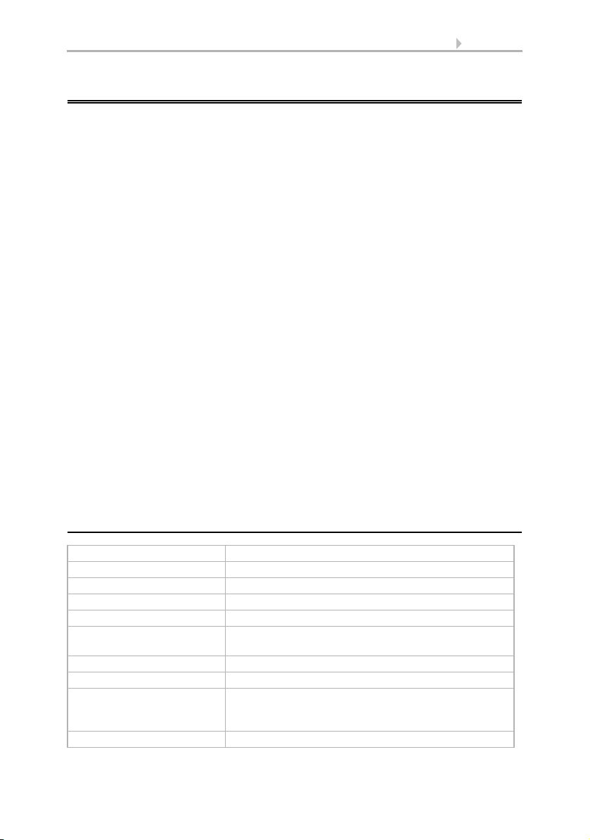
1.1. Technical specifications
Housing Plastic material
Colour White / translucent
Mounting On-wall
Protection category IP 44
Dimensions approx. 96 × 77 × 118 (W × H × D, mm)
Weight 230 V AC version: approx. 240 g
Ambient temperature Operation -30…+50°C, Storage -30…+70°C
Operating voltage Available for 230 V AC or for 24 V DC (20 V AC)
Current 230 V AC version: max. 20 mA
Data output KNX +/- bus terminal plug
Weather Station Suntracer KNX basic • Date of issue: 29.06.2012 • Technical changes reserved. Errors reserved.
24 V DC version: approx. 170 g
24 V DC version: max. 100 mA
Residual ripple 10%
Page 4
4 Description
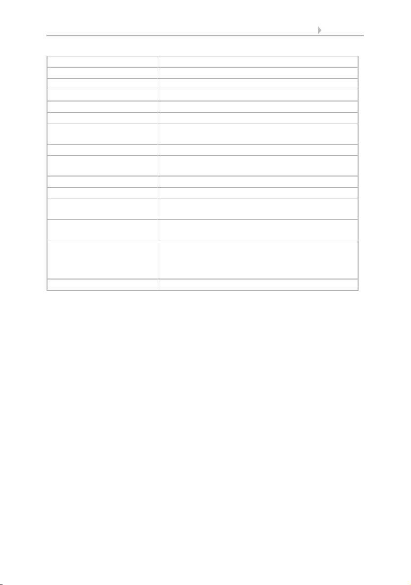
BCU type Own micro controller
PEI type 0
Group addresses max. 254
Allocations max. 255
Communication objects 222
Heating rain sensor approx. 1.2 W (230 V and 24 V)
Measurement range
temperature
Resolution (temperature) 0.1°C
Accuracy (temperature) ±1°C at -10…+85°C
Measurement range wind 0…70 m/s
Resolution (wind) <10% of the measured value
Accuracy (wind) ±25% at 0…15 m/s
Measurement range
brightness
Resolution (brightness) 1 lux at 0…120 lux
Accuracy (brightness) ±35%
-40…+80°C
±1.5°C at -25…+150°C
at an angle of attack of 45°, pole mounting
0…150 000 lux
2 lux at 121…1 046 lux
63 lux at 1 047…52 363 lux
423 lux at 52 364…150 000 lux
The following standards have been considered for the evaluation of the product in
terms of electro magnetic compatibility:
Transient emissions:
• EN 60730-1:2000 Section EMV (23, 26, H23, H26) (threshold category: B)
• EN 50090-2-2:1996-11 + A1:2002-01 (threshold category: B)
• EN 61000-6-3:2001 (threshold category: B)
Interference resistance:
• EN 60730-1:2000 Section EMV (23, 26, H23, H26)
• EN 50090-2-2:1996-11 + A1:2002-01
• EN 61000-6-1:2004
The product has been tested for the above mentioned standards by an accredited EMV
laboratory.
Weather Station Suntracer KNX basic • Date of issue: 29.06.2012 • Technical changes reserved. Errors reserved.
Page 5
5 Description
2. Installation and commissioning
2.1. Notes on installation
Warning, mains voltage!
National legal regulations are to be observed.
Installation, inspection, commissioning and troubleshooting of
the device must only be carried out by a competent electrician.
Disconnect all lines to be assembled, and take safety precautions against accidental
switch-on.
The device is exclusively intended for appropriate use. With each inappropriate change
or non-observance of the instructions for use, any warranty or guarantee claim will be
void.
After unpacking the device, check immediately for any mechanical damages. In case of
transport damage, this must immediately notified to the supplier.
If damaged, the device must not be put into operation.
If an operation without risk may supposedly not be guaranteed, the device must be put
out of operation and be secured against accidental operation.
The device must only be operated as stationary system, i.e. only in a fitted state and
after completion of all installation and start-up works, and only in the environment intended for this purpose.
Elsner Elektronik does not assume any liability for changes in standards after publication of this instruction manual.
2.1.1. Location
Select an assembly location at the building where wind, rain and sun may be collected
by the sensors unobstructedly. Do not assemble any construction components above
the weather station from where water may drop on to the rain sensor after it has stopped raining or snowing. The weather station may not be shaded by the building or for
example by trees. Leave at least 60 cm of free space beneath the weather station in order to enable a correct wind measurement and in order to avoid that the weather station is snowed in if there is heavy snowfall. Please ensure that the extended awning
does not cast shade on the unit, and that this is not protected from the wind.
Temperature measurements can also be affected by external influences such as by
warming or cooling of the building structure on which the sensor is mounted, (sunlight, heating or cold water pipes). Temperature variations from such sources of interference must be corrected in the ETS in order to ensure the specified accuracy of the
sensor (temperature offset).
Weather Station Suntracer KNX basic • Date of issue: 29.06.2012 • Technical changes reserved. Errors reserved.
Page 6
6 Description
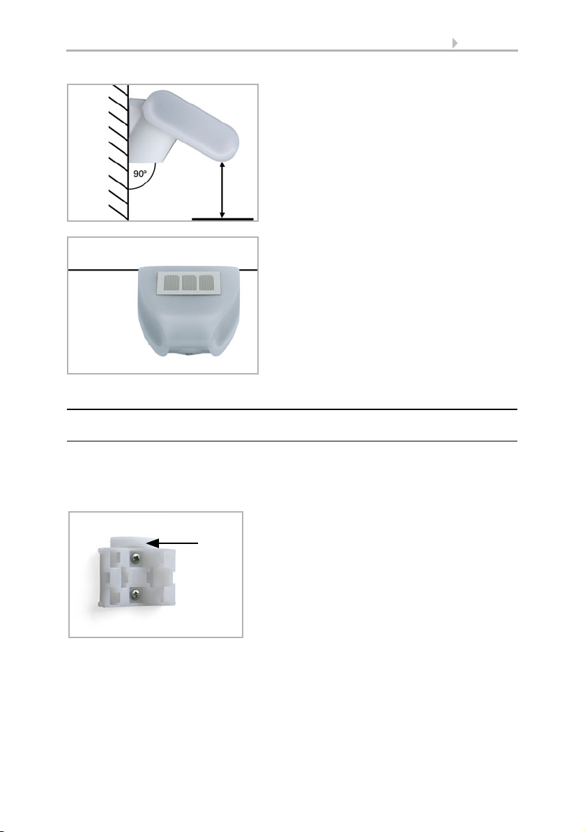
Fig. 1
The wind sensor must be mounted onto a
vertical wall (or pole).
Wall
or
pole
Fig. 2
The wind sensor must be mounted horizontally in the lateral direction.
Horizontal
Fig. 3
When wall mounting: flat side on wall, crescentshaped collar upward.
Collar
2.2. Mounting the weather station
2.2.1. Attaching the mount
The sensor comes with a combination wall/pole mount. The mount comes adhered by
adhesive strips to the rear side of the housing.
Fasten the mount vertically onto the wall or pole.
Weather Station Suntracer KNX basic • Date of issue: 29.06.2012 • Technical changes reserved. Errors reserved.
Page 7
7 Description
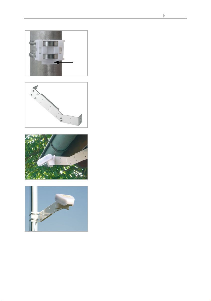
Fig. 4
When pole mounting: curved side on pole, collar
downward.
Collar
Fig. 5
An additional, optional accessory available from
Elsner Elektronik is an articulated arm for flexible wall, pole or beam mounting of the sensor.
Fig. 6
Example uses of the hinge arm mounting: With
the hinge arm mounting, the sensor peeps out
from beneath the roof overhang.
Fig. 7
Example uses of the hinge arm mounting: Fitting to a pole with worm drive hose clips
Weather Station Suntracer KNX basic • Date of issue: 29.06.2012 • Technical changes reserved. Errors reserved.
Page 8
8 Description
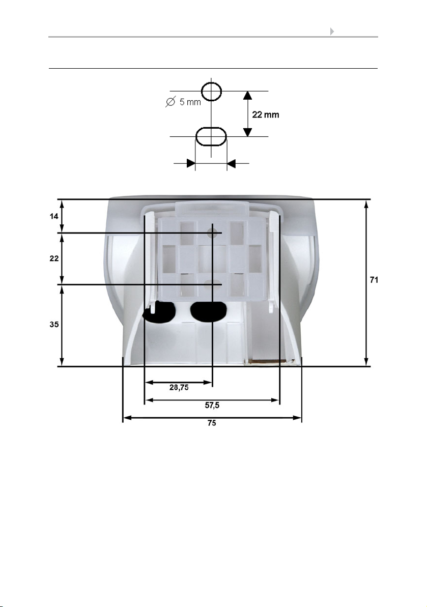
Langloch 7,5 x 5 mm
Fig. 8 a+b
Drill hole plan
Dimensions of rear side of
housing with bracket. Subject to change for technical
enhancement.
2.2.2. View of rear side and drill hole plan
Weather Station Suntracer KNX basic • Date of issue: 29.06.2012 • Technical changes reserved. Errors reserved.
Page 9

9 Description
Fig. 9
1 Cover with rain sensor
2 Cover snaps
3 Bottom part of housing
2
3
Unsnap cover
and remove upwards
1
2.2.3. Preparing the weather station
The weather station cover with the rain sensor snaps in on the left and right along the
bottom edge (see Fig.). Remove the weather station cover. Proceed carefully, so as not
to pull off the wire connecting the PCB in the bottom part with the rain sensor in the
cover (soldered cable connection in case of 230 V AC version, cable with plug in case
of 24 V DC version).
Push the power supply and bus connection cable through the rubber seal on the bottom of the weather station and connect voltage LN and bus +/- to the provided clamps.
For 24V devices the connection cable must be plugged in between the cover and circuit
board.
Weather Station Suntracer KNX basic • Date of issue: 29.06.2012 • Technical changes reserved. Errors reserved.
Page 10

2.2.4. PCB layout
Fig. 10
1 Cable connection to the rain
sensor in the housing cover
2 Opening for the cable for the
voltage supply
3 Tension clamp for voltage
supply (230 V AC),
suitable for massive conductors of up to 1.5 mm² or con-
ductors with fine wires
4 Opening for bus cable
5Slot for KNX clamp +/6 Programming pushbutton for
the teach-in of the device
7 Programming LED
231
6
7
4 5
Fig. 11
1 Slot for cable connection to
the rain sensor in the housing
cover
2 Tension clamp for voltage
supply (24 V DC/20 V AC),
suitable for massive conduc-
tors of up to 1.5 mm² or con-
ductors with fine wires
3 Opening for the cable for the
voltage supply
4 Opening for bus cable
5Slot for KNX clamp +/6 Programming pushbutton for
the teach-in of the device
7 Programming LED
231
6
7
4 5
230 V AC version
24 V DC version
10 Description
Weather Station Suntracer KNX basic • Date of issue: 29.06.2012 • Technical changes reserved. Errors reserved.
Page 11

11 Description
Fig. 12
Make sure the cover and bottom part are properly snapped together! This picture is looking at the closed sensor from underneath.
Fastening
Fig. 13
Push the housing from above into the fastened mount. The bumps on the mount must
snap into the rails in the housing.
2.2.5. Mounting the weather station
Close the housing by putting the cover back over the bottom part. The cover must snap
in on the left and right with a definite “click”.
To remove it, the weather station can be simply pulled upwards out of the mount,
against the resistance of the fastening.
2.3. Notes on mounting and commissioning
Do not open weather station if water (rain) might ingress: even some drops might damage the electronic system.
Observe the correct connections. Incorrect connections may destroy the weather station or connected electronic devices.
Please take care not to damage the temperature sensor (small blank at the bottom part
of the housing.) when mounting the weather station. Please also take care not to break
away or bend the cable connection between the blank and the rain sensor when connecting the weather station.
Remove all existing protection labels after installation.
The measured wind value and thus all other wind switching outputs may only be supplied 60 seconds after the supply voltage has been connected.
After the auxiliary voltage has been applied, the device will enter an initialisation phase
lasting 5 seconds. During this phase no information can be received via the bus.
Weather Station Suntracer KNX basic • Date of issue: 29.06.2012 • Technical changes reserved. Errors reserved.
Page 12

12 Maintenance
3. Maintenance
The sensor must regularly be checked for dirt twice a year and cleaned if necessary. In
case of severe dirt, the sensor may not work properly anymore.
As a precaution, the device should always be separated from
power supply for maintenance works (e.g. deactivate or remove
fuse).
Weather Station Suntracer KNX basic • Date of issue: 29.06.2012 • Technical changes reserved. Errors reserved.
Page 13

13 Transmission protocol
4. Transmission protocol
Units:
Temperatures in degree Celsius
Light in Lux
Wind in meters per second
4.1. List of all communication objects
Abbreviations EIS types:
1 Switching1/0
5 Floating decimal value
6 8 bit value
Abbreviations Flags:
C Communication
R Read
WWrite
T Transmit
No. Name Function EIS
type
0 Switching output dawn 1 C R T
1 Switching output rain 1 C R T
2 Logic input 1 1 C R W
3 Logic input 2 1 C R W
4 Logic input 3 1 C R W
5 Logic input 4 1 C R W
6 Logic input 5 1 C R W
7 Logic input 6 1 C R W
8 Logic input 7 1 C R W
9 Logic input 8 1 C R W
Flags
10 Temperature sensor failure Output 1 C R T
11 Wind sensor failure Output 1 C R T
12 Measured temperature value 5 C R T
13 Requirement min/max temperature Requirement 1 C R W
14 Lowest measured temperature
value
15 Highest measured temperature
value
16 Min/max temperature reset Reset of tempera-
Weather Station Suntracer KNX basic • Date of issue: 29.06.2012 • Errors excepted. Subject to technical changes.
Sends min. temperature
Sends max. temperature
ture
5C R T
5C R T
1C R W
Page 14

14 Transmission protocol
No. Name Function EIS
Flags
type
17 Temperature threshold value 1 Target value 5 C R W
18 Temperature threshold value 1 Actual value 5 C R T
19 Temperature threshold value 2 Target value 5 C R W
20 Temperature threshold value 2 Actual value 5 C R T
21 Temperature threshold value 3 Target value 5 C R W
22 Temperature threshold value 3 Actual value 5 C R T
23 Temperature threshold value 4 Target value 5 C R W
24 Temperature threshold value 4 Actual value 5 C R T
25 Switching output
1C R T
temperature threshold value 1
26 Switching output
1C R T
temperature threshold value 2
27 Switching output
1C R T
temperature threshold value 3
28 Switching output
1C R T
temperature threshold value 4
29 Measured value of wind force 5 C R T
30 Requirement max. wind force Requirement 1 C R W
31 Highest measured value of wind
force
Sends max. wind
force
5C R T
32 Max. wind force reset Reset of wind force 1 C R W
33 Wind force threshold value 1 Target value 5 C R W
34 Wind force threshold value 1 Actual value 5 C R T
35 Wind force threshold value 2 Target value 5 C R W
36 Wind force threshold value 2 Actual value 5 C R T
37 Wind force threshold value 3 Target value 5 C R W
38 Wind force threshold value 3 Actual value 5 C R T
39 Switching output
1C R T
wind force threshold value 1
40 Switching output
1C R T
wind force threshold value 2
41 Switching output
1C R T
wind force threshold value 3
42 Measured light value 5 C R T
43 Brightness threshold value 1 Target value 5 C R W
44 Brightness threshold value 1 Actual value 5 C R T
45 Brightness threshold value 2 Target value 5 C R W
46 Brightness threshold value 2 Actual value 5 C R T
47 Brightness threshold value 3 Target value 5 C R W
48 Brightness threshold value 3 Actual value 5 C R T
Weather Station Suntracer KNX basic • Date of issue: 29.06.2012 • Errors excepted. Subject to technical changes.
Page 15

15 Transmission protocol
No. Name Function EIS
Flags
type
49 Switching output
1C R T
light threshold value 1
50 Switching output
1C R T
light threshold value 2
51 Switching output
1C R T
light threshold value 3
52 Dawn threshold value 1 Target value 5 C R W
53 Dawn threshold value 1 Actual value 5 C R T
54 Dawn threshold value 2 Target value 5 C R W
55 Dawn threshold value 2 Actual value 5 C R T
56 Dawn threshold value 3 Target value 5 C R W
57 Dawn threshold value 3 Actual value 5 C R T
58 Switching output
1C R T
dawn threshold value 1
59 Switching output
1C R T
dawn threshold value 2
60 Switching output
1C R T
dawn threshold value 3
61 AND logic 1 Switching output 1 C R T
62 AND logic 1 8 Bit output A 6 C R T
63 AND logic 1 8 Bit output B 6 C R T
64 AND logic 2 Switching output 1 C R T
65 AND logic 2 8 Bit output A 6 C R T
66 AND logic 2 8 Bit output B 6 C R T
67 AND logic 3 Switching output 1 C R T
68 AND logic 3 8 Bit output A 6 C R T
69 AND logic 3 8 Bit output B 6 C R T
70 AND logic 4 Switching output 1 C R T
71 AND logic 4 8 Bit output A 6 C R T
72 AND logic 4 8 Bit output B 6 C R T
73 AND logic 5 Switching output 1 C R T
74 AND logic 5 8 Bit output A 6 C R T
75 AND logic 5 8 Bit output B 6 C R T
76 AND logic 6 Switching output 1 C R T
77 AND logic 6 8 Bit output A 6 C R T
78 AND logic 6 8 Bit output B 6 C R T
79 AND logic 7 Switching output 1 C R T
80 AND logic 7 8 Bit output A 6 C R T
81 AND logic 7 8 Bit output B 6 C R T
Weather Station Suntracer KNX basic • Date of issue: 29.06.2012 • Errors excepted. Subject to technical changes.
Page 16

16 Transmission protocol
No. Name Function EIS
Flags
type
82 AND logic 8 Switching output 1 C R T
83 AND logic 8 8 Bit output A 6 C R T
84 AND logic 8 8 Bit output B 6 C R T
85 OR logic 1 Switching output 1 C R T
86 OR logic 1 8 Bit output A 6 C R T
87 OR logic 1 8 Bit output B 6 C R T
88 OR logic 2 Switching output 1 C R T
89 OR logic 2 8 Bit output A 6 C R T
90 OR logic 2 8 Bit output B 6 C R T
91 OR logic 3 Switching output 1 C R T
92 OR logic 3 8 Bit output A 6 C R T
93 OR logic 3 8 Bit output B 6 C R T
94 OR logic 4 Switching output 1 C R T
95 OR logic 4 8 Bit output A 6 C R T
96 OR logic 4 8 Bit output B 6 C R T
97 OR logic 5 Switching output 1 C R T
98 OR logic 5 8 Bit output A 6 C R T
99 OR logic 5 8 Bit output B 6 C R T
100 OR logic 6 Switching output 1 C R T
101 OR logic 6 8 Bit output A 6 C R T
102 OR logic 6 8 Bit output B 6 C R T
103 OR logic 7 Switching output 1 C R T
104 OR logic 7 8 Bit output A 6 C R T
105 OR logic 7 8 Bit output B 6 C R T
106 OR logic 8 Switching output 1 C R T
107 OR logic 8 8 Bit output A 6 C R T
108 OR logic 8 8 Bit output B 6 C R T
Weather Station Suntracer KNX basic • Date of issue: 29.06.2012 • Errors excepted. Subject to technical changes.
Page 17

17 Setting of parameters
5. Setting of parameters
5.1. General settings
Send measured values cyclically every 5 sec • 10 sec • 30 sec • … • 2 h
Send switching outputs cyclically every 5 sec • 10 sec • 30 sec • … • 2 h
Logic outputs cyclical send all 5 sec • 10 sec • 30 sec • … • 2 h
Communication objects logic inputs do not release • release
Communication object
switching output night
"(The output reacts with a delay of approx.
1 minute; “night” is recognised when light
is below 10 lux)
Communication object
Switching output rain
(After approx. 8 minutes without rain, the
output is reset)
Transmission delay of the switching
outputs after power up and programming
Maximum telegram quota 1 • 2 • 3 • 5 • 10 • 20 telegrams per second
Weather Station Suntracer KNX basic • Date of issue: 29.06.2012 • Errors excepted. Subject to technical changes.
• not send
• send in case of change
• send inversely in case of change
• send in case of change and cyclically
• send in case of change and cyclically
inverse
• not send
• send in case of change
• send inversely in case of change
• send in case of change and cyclically
• send in case of change and cyclically
inverse
5 sec • 10 sec • 30 sec • … • 2 h
Page 18

5.2. Temperature
18 Setting of parameters
Measured value • not send
From a temperature change of 0.5°C • 1°C • 2°C • 3°C • 4°C • 5°C
Temperature offset in 0.1°C -50 … 50; 0
Send and reset of the min. and max.
temperature value on request
Threshold value 1 / 2 / 3 / 4 not active • active
• send cyclically
• send in case of change
• send in case of change and cyclically
do not release • release
5.2.1. Temperature threshold value 1 / 2 / 3 / 4
If the threshold is set by parameters:
Threshold value is set by Parameter
Threshold value in 0,1°C
valid until 1st communication
Hysteresis of the threshold value in 0.1°C. 0 …100; 30
If the threshold is set by communication objects, a threshold which is valid
until the first communication of a new threshold must be determined for the
initial operation:
Threshold value is set by Communication object
Start of threshold value in 0.1°C
valid untiöl 1st communication
Hysteresis of the threshold value in 0.1°C 0...100; 30
The thresholds set at last by communication objects are saved in EEPROM in order to
maintain them in case of voltage breakdown and to provide them as soon as there is
voltage supply again.
-300 … 800; 200
-300 … 800; 200
In case of an already commissioned weather station, the threshold which has
been communicated at last may be used:
As soon as a threshold has been set by means of a parameter or by means of a communication object, the threshold set at last remains until a new threshold has been
transmitted by a communication object.
Switching output:
Activation delay none • 1 s • 1 min... • 2 h
Switch-off delay none • 1 s • 1 min... • 2 h
Weather Station Suntracer KNX basic • Date of issue: 29.06.2012 • Errors excepted. Subject to technical changes.
Page 19

19 Setting of parameters
Output switches at • TV above = ON TV-Hyst. below = OFF
Communication object switching output
temperature threshold value 1
• TV below = ON TV-Hyst. above = OFF
• do not send
• send in case of change
• send inverted in case of change
• send in case of change and periodically
• send inverted in case of change and periodically
5.3. Wind force
Measured value • not send
From a wind force change of 1 m/sec … 4 m/sec
Send and reset of the maximum
wind load value on request
Threshold value 1 / 2 / 3 not active • active
5.3.1. Wind threshold value 1 / 2 / 3
Threshold value
Threshold value setpoint per Parameter • Communication object
If the threshold value is set per Parameter:
Threshold value in 0,1 m/s 0 … 350; 40
Hysteresis of the threshold value in % 0 … 250; 20
If the threshold value is set per Communication object:
The value communicated last shall be
maintained
Start threshold value in 0,1 m/s
valid until 1. communication
(only if the value communicated last is
„not“ maintained or „after restoration of
voltage“)
• cyclically send
• send in case of change
• send in case of change and cyclically
do not release • release
• not
• after restoration of voltage
(the changes threshold value may be
saved at least 100,000 times)
• after restoration of voltage and
programming (Attention: Do not use
for first commissioning)
0 … 350; 40
Weather Station Suntracer KNX basic • Date of issue: 29.06.2012 • Errors excepted. Subject to technical changes.
Page 20

20 Setting of parameters
Type of threshold change • Absolute value with a 16 bit
communication object
• Increment / decrement with one
communication object
• Increment / decrement with two
communication objects
Step size
0,1 m/s … 5 m/s; 1 m/s
(only if sending „Increment/decrement“)
Hysteresis of the threshold value in % 0 … 250; 20
Switching output
Output is at
(TV = Threshold Value)
• TV above = 1 | TV - Hyst. below = 0
• TV above = 0 | TV - Hyst. below= 1
• TV below = 1 | TV + Hyst. above = 0
• TV below = 0 | TV + Hyst. above = 1
Switching delay from 0 to 1 none • 1 sec … 2 h
Switching delay from 1 to 0 none • 1 sec … 2 h
Switching output sends • not
• on change
• on change to 1
• on change to 0
• on change and periodically
• on change to 1 and periodically
• on change to 0 and periodically
send periodically all
5 sec … 2 h
(only if sending “periodically“)
Blocking
„Blocking“ only appears if using „Switching output sends on change“
Use block of the switching output Yes • No
If block of the switching output is used:
Use block of the switching output Yes
Evaluation of the blocking object • if value 1: block | if value 0: release
• if value 0: block | if value 1: release
Value of the blocking object before
0 • 1
1. communication
Behaviour of the switching output
with blocking
• do not send telegram
•send 0
•send 1
Behaviour of the switching output
with release (Auswahl je nach vorheriger
Einstellung möglich)
• do not send telegram
• send status of the switching output
• if switching output = 1 => send 1
• if switching output = 0 => send 0
Weather Station Suntracer KNX basic • Date of issue: 29.06.2012 • Errors excepted. Subject to technical changes.
Page 21

5.4. Brightness
21 Setting of parameters
Measured value • do not send
From change in % 1 … 50; 10
Threshold value 1 / 2 / 3 not active • active
• send cyclically
• send in case of change
• send in case of change and cyclically
5.4.1. Brightness threshold value 1 / 2 / 3
Threshold value in klux 1 … 99; 5
Hysteresis of the threshold value in klux 0 … 99; 2
All other parameters correspond to the parameters of the temperature thresholds
(see there).
5.5. Dawn
Threshold value 1 / 2 / 3 Not active • active
5.5.1. Dawn threshold value 1 / 2 / 3
Threshold value in lux 1 … 1000; 200
Hysteresis of the threshold value in lux 0 … 1000; 50
All other parameters correspond to the parameters of the temperature thresholds
(see there).
5.6. AND Logic
Logic 1 / 2 / 3 / 4 / 5 / 6 / 7 / 8 not active • active
5.6.1. AND Logic 1 / 2 / 3 / 4 / 5 / 6 / 7 / 8
1. / 2. / 3. / 4. Input • do not use
Logic output sends • not
Logic output sends “one 1 bit Object“:
Logic output sends one 1 bit object
if logic = 1 object value 1 • 0
if logic = 0 object value 1 • 0
Weather Station Suntracer KNX basic • Date of issue: 29.06.2012 • Errors excepted. Subject to technical changes.
• all switching events which the sensor
provides (see “Linkage inputs of the AND
logic”)
• one 1 bit object
• two 8 bit objects
Page 22

22 Setting of parameters
Communication object
AND Logic 1 sends
send cyclically every
(only if sending “cyclically”)
• in case of the change of logic
• in case of the change of logic to 1
• in case of the change of logic to 0
• in case of the change of logic and
cyclically
• in case of the change of logic to 1 and
cyclically
• in case of the change of logic to 0 and
cyclically
5 sec … 2 h
Logic output sends “two 8 bit objects“:
Logic output sends two 8 bit objects
if logic = 1 object A value 0 … 255; 127
if logic = 0 object A value 0 … 255
if logic = 1 object B value 0 … 255; 127
if logic = 0 object B value 0 … 255
Communication objects
AND Logic 1 A and B sends
send cyclically every
(only if sending “cyclically”)
• in case of the change of logic
• in case of the change of logic to 1
• in case of the change of logic to 0
• in case of the change of logic and
cyclically
• in case of the change of logic to 1 and
cyclically
• in case of the change of logic to 0 and
cyclically
5 sec … 2 h
5.6.2. Linkage inputs of AND logic
do not use
Night = 1
Night = 0
Dawn threshold value 1
Dawn threshold value 1 inverted
Dawn threshold value 2
Dawn threshold value 2 inverted
Dawn threshold value 3
Dawn threshold value 3 inverted
Brightness threshold value 1
Brightness threshold value 1 inverted
Brightness threshold value 2
Brightness threshold value 2 inverted
Brightness threshold value 3
Brightness threshold value 3 inverted
Weather Station Suntracer KNX basic • Date of issue: 29.06.2012 • Errors excepted. Subject to technical changes.
Page 23

23 Setting of parameters
Communication object logic input 1
Communication object logic input 1 inverted
Communication object logic input 2
Communication object logic input 2 inverted
Communication object logic input 3
Communication object logic input 3 inverted
Communication object logic input 4
Communication object logic input 4 inverted
Communication object logic input 5
Communication object logic input 5 inverted
Communication object logic input 6
Communication object logic input 6 inverted
Communication object logic input 7
Communication object logic input 7 inverted
Communication object logic input 8
Communication object logic input 8 inverted
Rain yes
Rain no
Failure temperature
Failure temperature inverted
Failure wind
Failure wind inverted
Temperature threshold value 1
Temperature threshold value 1 inverted
Temperature threshold value 2
Temperature threshold value 2 inverted
Temperature threshold value 3
Temperature threshold value 3 inverted
Temperature threshold value 4
Temperature threshold value 4 inverted
Wind threshold value 1
Wind threshold value 1 inverted
Wind threshold value 2
Wind threshold value 2 inverted
Wind threshold value 3
Wind threshold value 3 inverted
5.7. OR Logic
Logic 1 / 2 / 3 / 4 / 5 / 6 / 7 / 8 not active • active
)
5.7.1. OR Logic 1 / 2 / 3 / 4 / 5 / 6 / 7 / 8
1. / 2. / 3. / 4. Input • do not use
Weather Station Suntracer KNX basic • Date of issue: 29.06.2012 • Errors excepted. Subject to technical changes.
• all switching events which the sensor provides (see “Linkage inputs of the OR logic”)
Page 24

24 Setting of parameters
Logic output sends • one 1 bit object
• two 8 bit objects
All settings of the OR logic correspond to those of the AND logic.
5.7.2. Linkage inputs of OR logic
The linkage inputs of the OR logic correspond with the parameters of the AND logic.
The OR logic is additionally provided with the following inputs:
AND logic output 1
AND logic output 1 inverted
AND logic output 2
AND logic output 2 inverted
AND logic output 3
AND logic output 3 inverted
AND logic output 4
AND logic output 4 inverted
AND logic output 5
AND logic output 5 inverted
AND logic output 6
AND logic output 6 inverted
AND logic output 7
AND logic output 7 inverted
AND logic output 8
AND logic output 8 inverted
Weather Station Suntracer KNX basic • Date of issue: 29.06.2012 • Errors excepted. Subject to technical changes.
 Loading...