

Page 1

Weather Station for KNX
Installation and Adjustment
Page 2

Product description...........................................................................................3
Technical data...............................................................................................................4
PCB layout ....................................................................................................................5
230 V AC version.................................................................................................................................. 5
24 V DC version.................................................................................................................................... 6
Installation and commissioning ........................................................................7
Location ........................................................................................................................7
Attaching the mount............................................................................................................................ 8
View of rear side and drill hole plan .................................................................................................. 9
Preparing the weather station .......................................................................................................... 10
Aligning the DCF77 antenna............................................................................................................. 11
Mounting the weather station .......................................................................................................... 11
Details for the installation ................................................................................................................. 12
Maintenance................................................................................................................12
Transmission protocol..................................................................................... 13
Abbreviations..................................................................................................................................... 13
Listing of all communication objects..........................................................................13
Setting of parameters .....................................................................................21
General settings ..........................................................................................................21
Location ......................................................................................................................22
Position of the sun......................................................................................................24
Position of the sun in sector 1 / 2 / 3 / 4 / 5 ...................................................................................... 25
Temperature................................................................................................................27
Temperature threshold 1 / 2 / 3 / 4 ................................................................................................... 28
Wind force...................................................................................................................31
Wind force threshold 1 / 2 / 3............................................................................................................ 32
Brightness ...................................................................................................................33
Brightness threshold value 1 / 2 / 3.................................................................................................. 34
Dawn...........................................................................................................................35
Dawn threshold value 1 / 2 / 3 .......................................................................................................... 35
Calendar time switch ..................................................................................................36
Calendar time switch period 1 / 2 / 3................................................................................................ 37
Calendar time switch period 1 / 2 / 3, sequence 1 / 2 ..................................................................... 38
Week time switch........................................................................................................39
Weekly watch Mon, Tue, Wed, Thu, Fri, Sat, Sun 1 … 4................................................................ 40
AND logic....................................................................................................................41
AND logic 1 / 2 / 3 / 4 / 5 / 6 / 7 / 8 ..................................................................................................... 41
Linkage inputs of AND logic ............................................................................................................. 43
OR logic.......................................................................................................................47
OR logic 1 / 2 / 3 / 4 / 5 / 6 / 7 / 8 ........................................................................................................ 47
Linkage inputs of OR logic ................................................................................................................ 47
Suntracer KNX • from software version 1.17, ETS programme version 1.4 • Status: 14.05.2010.
Errors excepted. Subject to technical changes
Page 3

Elsner Elektronik GmbH Steuerungs- und Automatisierungstechnik
Herdweg 7 • D-75391 Gechingen • Germany
Phone.: +49 (0) 70 56/93 97-0 • Fax: +49 (0) 70 56/93 97-20
info@elsner-elektronik.de • www.elsner-elektronik.de
2
Page 4
Product description
The Weather Station
brightness. It perceives precipitation and receives the DCF77 signal for date and time.
Furthermore, the exact position of the sun (azimuth and elevation) is calculated on the
basis of location coordinates and time.
The calculation of the position of the sun is optimised for
UTC -1...+3. The device therefore may only be applied within
Europe. For other time zones, please use Suntracer KNX-GPS
Weather Station.
All data may be used for the control of switching outputs which depend on threshold
values. The states may be linked by means of AND and OR logic gates.
The compact housing of
electronics and the electronics of the bus connection.
Functions and Operation:
• Brightness and position of the sun: The current light intensity is measured by
means of a sensor. At the same time, Suntracer KNX calculates the position of the
sun (azimuth and elevation) on the basis of time and location. The necessary
position coordinates (degree of longitude and latitude) are entered into the ETS
software
• Wind measurement: The measurement of wind speed is accomplished
electronically and thus noiseless and reliable even in case of hail, snow and minus
temperature. Air swirls and up-draught in the radius of the weather station are
collected, too
• Precipitation perception: The surface of the sensor is heated so that only drops
and flakes are recognised as precipitation but not fog or dew. If it stops raining or
snowing, the sensor dries quickly and the precipitation message ends
• Temperature measurement
• Week and calendar time switch: The weather station receives time and date
from the integrated DCF77 receiver. The week time switch operates up to 4
different periods each day. With the calendar time switch, you may determine 3
additional periods where the time switch accomplishes up to 2 activations and
deactivations each day. The Switching outputs can be used as communication
objects. The switching times are set by parameter or via communication objects
• Switching outputs for all measured and calculated values (Threshold values can
be set by parameter or via communication objects)
• 8 AND and 8 OR logic gates with each 4 inputs. Every switching incident as
well as 8 logic inputs (in the form of communication objects) may be used as
inputs for the logic gates. The output of each gate may optionally be configured as
1 bit or 2 x 8 bits
measures temperature, wind speed and
stores the sensor system, the evaluation
3
Page 5

Configuration is accomplished by means of the KNX software ETS. The programme
file for KNX software ETS (format VD2) is ready for download on the Elsner Elektronik
website under www.elsner-elektronik.de in the “Service” menu.
Technical data
Housing: Plastic material
Colour: White / translucent
Mounting: On-wall
Protection category: IP 44
Dimensions: approx. 96 × 77 × 118 (W × H × D, mm)
Weight: 230 V AC version: approx. 240 g
24 V DC version: approx. 170 g
Ambient temperature: Operation -30…+50°C, Storage -30…+70°C
Operating voltage: Available for 230 V AC or for 24 V DC (20 V AC)
Current: 230 V AC version: max. 20 mA
24 V DC version: max. 100 mA
Residual ripple 10%
If switching power supply units are applied, the quality of the radio clock reception may
be influenced.
Data output: KNX +/- bus terminal plug
BCU type: Own micro controller
PEI type: 0
Group addresses: max. 254
Allocations: max. 255
Communication objects: 222
Heating rain sensor: approx. 1.2 W (230 V and 24 V)
Measurement range temperature: -40…+80°C
Resolution: 0.1°C
Accuracy:
±0.5°C at +10…+50°C
±1°C at -10…+85°C
±1.5°C at -25…+150°C
Measurement range wind: 0…70 m/s
Resolution: <10% of the measured value
Accuracy: ±25% at 0…15 m/s
at an angle of attack of 45°, pole mounting
4
Page 6
Measurement range brightness: 0…150 000 lux
Resolution:
1 lux at 0…120 lux
2 lux at 121…1 046 lux
63 lux at 1 047…52 363 lux
423 lux at 52 364…150 000 lux
Accuracy: ±35%
The following standards have been considered for the evaluation of the product in
terms of electro magnetic compatibility:
Transient emissions:
• EN 60730-1:2000 Section EMV (23, 26, H23, H26) (threshold category: B)
• EN 50090-2-2:1996-11 + A1:2002-01 (threshold category: B)
• EN 61000-6-3:2001 (threshold category: B)
Interference resistance:
• EN 60730-1:2000 Section EMV (23, 26, H23, H26)
• EN 50090-2-2:1996-11 + A1:2002-01
• EN 61000-6-1:2004
The product has been tested for the above mentioned standards by an accredited EMV
laboratory.
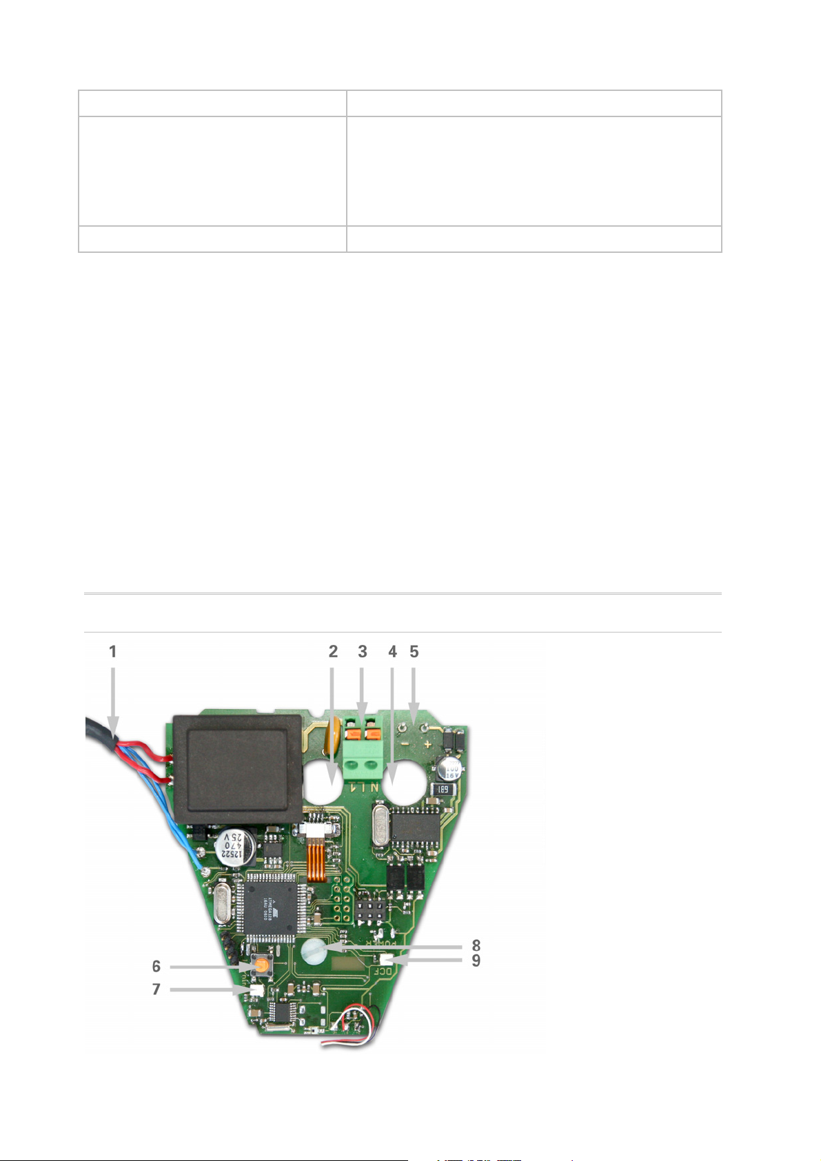
PCB layout
230 V AC version
Fig. 1
5
Page 7
1 Cable connection to the rain sensor in the housing cover
2 Opening for the cable for the voltage supply
3 Tension clamp for voltage supply (230 V AC),
suitable for massive conductors of up to 1.5 mm² or conductors with fine wires
4 Opening for bus cable
5 Slot for KNX clamp +/6 Programming pushbutton for the teach-in of the device
7 Programming LED
8 Adjusting screw DCF77 antenna
9 Control LED DCF77 reception
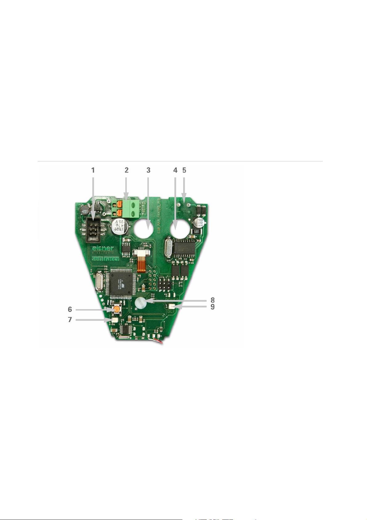
24 V DC version
Fig. 2
1 Slot for cable connection to the rain sensor in the housing cover
2 Tension clamp for voltage supply (24 V DC/20 V AC),
suitable for massive conductors of up to 1.5 mm² or conductors with fine wires
3 Opening for the cable for the voltage supply
4 Opening for bus cable
5 Slot for KNX clamp +/6 Programming pushbutton for the teach-in of the device
7 Programming LED
8 Adjusting screw DCF77 antenna
9 Control LED DCF77 reception
6
Page 8

Installation and commissioning
Attention! Mains voltage! The legal national regulations
must be complied with.
Installation, inspection, commissioning and troubleshooting of the weather station must
only be carried out by a competent electrician. Disconnect all lines to be assembled, and
take safety precautions against accidental switch-on.
The weather station is exclusively intended for appropriate use. With each inappropriate
change or non-observance of the instructions for use, any warranty or guarantee claim
will be void.
After unpacking the device, check immediately for any mechanical damages. In case of
transport damage, this must immediately notified to the supplier.
If damaged, the weather station must not be put into
operation.
If an operation without risk may supposedly not be guaranteed, the device must be put
out of operation and be secured against accidental operation.
The weather station must only be operated as stationary system, i.e. only in a fitted
state and after completion of all installation and start-up works, and only in the
environment intended for this purpose.
Elsner Elektronik does not assume any liability for changes in standards after
publication of this instruction manual.
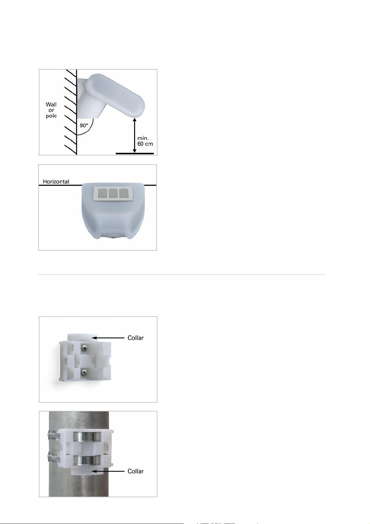
Location
Select an assembly location at the building where wind, rain and sun may be collected
by the sensors unobstructedly. Do not assemble any construction components above
the weather station from where water may drop on to the rain sensor after it has
stopped raining or snowing. The weather station may not be shaded by the building or
for example by trees. Leave at least 60 cm of free space beneath the weather station in
order to enable a correct wind measurement and in order to avoid that the weather
station is snowed in if there is heavy snowfall.
Iron constructions or huge metal sheets directly behind or in the vicinity of the weather
station reduce the reception quality of the assembled radio clock receiver. Please take
this into consideration when selecting the assembly location. The reception of the DCF
signal may also be disturbed or made impossible by magnetic fields, emitters and
7
Page 9
interfering fields of electrical consumers (e.g. fluorescent tubes, illuminated advertising,
switching power supply units, etc.).
Fig. 3: The weather station must be mounted
onto a vertical wall (or pole).
Fig.4: The weather station must be mounted
horizontally in the lateral direction.
Attaching the mount
The weather station comes with a combination wall/pole mount. The mount comes
adhered by adhesive strips to the rear side of the housing.
Fasten the mount vertically onto the wall or pole.
Fig. 5: When wall mounting: flat side on wall,
crescent-shaped collar upward.
Fig. 6: When pole mounting: curved side on pole,
collar downward.
8
Page 10
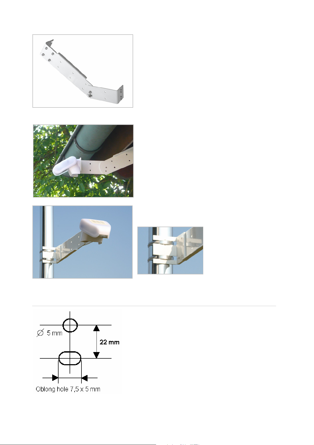
Fig. 7: An additional, optional accessory
available from Elsner Elektronik is an articulated
arm for flexible wall, pole or beam mounting of
the weather station.
Examples for the application of the hinge arm mounting:
Ex.1: With the hinge arm mounting, the weather
station projects from beneath the roof. Sun, wind
and precipitation can be measured unhindered by
the sensors.
Ex. 2: Pole-mounting with mounting brackets.
View of rear side and drill hole plan
Fig. 8a: Drill hole plan
9
Page 11
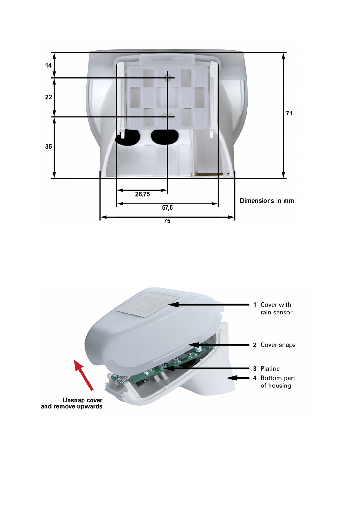
Fig.8b: Dimensions of rear side of housing with bracket. Subject to change for technical
enhancement
Preparing the weather station
Fig. 9
The weather station cover with the rain sensor snaps in on the left and right along the
bottom edge (see Fig.). Remove the weather station cover. Proceed carefully, so as not
to pull off the wire connecting the PCB in the bottom part with the rain sensor in the
10
Page 12

cover (soldered cable connection in case of 230 V AC version, cable with plug in case of
24 V DC version).
Push the power supply and bus connection cable through the rubber seal on the bottom
of the weather station and connect voltage LN and bus +/- to the provided clamps.
Aligning the DCF77 antenna
The antenna for DCF77 reception of date and time is located under the PCB in the
housing. Using the set screw (see chapter “PCB layout”, No. 8), you can turn the
antenna by up to 180° in order to achieve the best alignment. You know you are getting
reception when the control LED (No. 9) flashes regularly once every second (in second
59, the flashing interrupts once) The flashing may be displayed in the ETS programme
file (also see chapter “Setting of parameters: general settings“).
Mounting the weather station
Close the housing by putting the cover back over the bottom part. The cover must snap
in on the left and right with a definite “click”.
Fig. 10: Make sure the cover and bottom part are
properly snapped together! This picture is
looking at the closed weather station from
underneath.
Fig. 11: Push the housing from above into the
fastened mount. The bumps on the mount must
snap into the rails in the housing.
To remove it, the weather station can be simply pulled upwards out of the mount,
against the resistance of the fastening.
11
Page 13
Details for the installation
Do not open weather station if water (rain) might ingress: even some
drops might damage the electronic system.
Observe the correct connections. Incorrect connections may destroy the weather station
or connected electronic devices.
Please take care not to damage the temperature sensor (small blank at the bottom part
of the housing.) when mounting the weather station. Please also take care not to break
away or bend the cable connection between the blank and the rain sensor when
connecting the weather station.
Remove all existing protection labels after installation.
The measured wind value and thus all other wind switching outputs may only be
supplied 60 seconds after the supply voltage has been connected.
Maintenance
The weather station must regularly be checked for dirt twice a year and cleaned if
necessary. In case of severe dirt, the wind sensor may not work properly anymore, there
might be a permanent rain message or the station may not identify the sun anymore.
As a precaution, the weather station should always be
separated from power supply for maintenance works (e.g.
deactivate or remove fuse).
12
Page 14

Transmission protocol
Units: Temperatures in degree Celsius
Light in Lux
Wind in meters per second
The DCF signal may be slightly disturbed. It is possible that there is no radio clock
reception for a longer period of time. Therefore only use the indicated time for
synchronisation purposes of a clock which is operated parallel in your system. For this
purpose it is advisable to use second 0.
Abbreviations
EIS types:
EIS 1 Switching 1/0
EIS 3 Time
EIS 4 Date
EIS 5 Floating decimal value
EIS 6 8 bit value
Flags:
C Communication
R Read
W Write
T Transmit
Listing of all communication objects
No. Name Function EIS type Flags
0 DCF date 4 C R T W
1 DCF time 3 C R T W
2 Date and time requirement 1 C R W
3 Switching output dawn 1 C R T
4 Switching output rain 1 C R T
5 Logic input 1 1 C R W
6 Logic input 2 1 C R W
7 Logic input 3 1 C R W
8 Logic input 4 1 C R W
9 Logic input 5 1 C R W
10 Logic input 6 1 C R W
11 Logic input 7 1 C R W
12 Logic input 8 1 C R W
13
Page 15

No. Name Function EIS type Flags
13 Sun position azimuth 5 C R T
14 Sun position elevation 5 C R T
15 Switching output sun in sector 1 1 C R T
16 Switching output sun in sector 2 1 C R T
17 Switching output sun in sector 3 1 C R T
18 Switching output sun in sector 4 1 C R T
19 Switching output sun in sector 5 1 C R T
20 Measured temperature value 5 C R T
21 Requirement min/max
Requirement 1 C R W
temperature
22 Lowest measured temperature
value
23 Highest measured temperature
value
24 Min/max temperature reset Reset of
Sends min.
temperature
Sends max.
temperature
5 C R T
5 C R T
1 C R W
temperature
25 Temperature threshold value 1 Target value 5 C R W
26 Temperature threshold value 1 Actual value 5 C R T
27 Temperature threshold value 2 Target value 5 C R W
28 Temperature threshold value 2 Actual value 5 C R T
29 Temperature threshold value 3 Target value 5 C R W
30 Temperature threshold value 3 Actual value 5 C R T
31 Temperature threshold value 4 Target value 5 C R W
32 Temperature threshold value 4 Actual value 5 C R T
33 Switching output temperature
1 C R T
threshold value 1
34 Switching output temperature
1 C R T
threshold value 2
35 Switching output temperature
1 C R T
threshold value 3
36 Switching output temperature
1 C R T
threshold value 4
37 Measured value of wind force 5 C R T
38 Requirement max. wind force Requirement 1 C R W
39 Highest measured value of wind
force
40 Max. wind force reset Reset of wind
Sends max. wind
force
5 C R T
1 C R W
force
41 Wind force threshold value 1 Target value 5 C R W
14
Page 16

No. Name Function EIS type Flags
42 Wind force threshold value 1 Actual value 5 C R T
43 Wind force threshold value 2 Target value 5 C R W
44 Wind force threshold value 2 Actual value 5 C R T
45 Wind force threshold value 3 Target value 5 C R W
46 Wind force threshold value 3 Actual value 5 C R T
47 Switching output wind force
1 C R T
threshold value 1
48 Switching output wind force
1 C R T
threshold value 2
49 Switching output wind force
1 C R T
threshold value 3
50 Measured light value 5 C R T
51 Brightness threshold value 1 Target value 5 C R W
52 Brightness threshold value 1 Actual value 5 C R T
53 Brightness threshold value 2 Target value 5 C R W
54 Brightness threshold value 2 Actual value 5 C R T
55 Brightness threshold value 3 Target value 5 C R W
56 Brightness threshold value 3 Actual value 5 C R T
57 Switching output light threshold
1 C R T
value 1
58 Switching output light threshold
1 C R T
value 2
59 Switching output light threshold
1 C R T
value 3
60 Activation time period 1,
sequence 1
61 Switch off time period 1,
sequence 1
62 Switching output calendar time
switch
63 Activation time period 1,
sequence 2
64 Switch off time period 1,
sequence 2
65 Switching output calendar time
switch
66 Activation time period 2,
sequence 1
67 Switch off time period 2,
sequence 1
Calendar time
switch
Calendar time
switch
Period 1,
sequence 1
Calendar time
switch
Calendar time
switch
Period 1,
sequence 2
Calendar time
switch
Calendar time
switch
3 C R W
3 C R W
1 C R T
3 C R W
3 C R W
1 C R T
3 C R W
3 C R W
15
Page 17

No. Name Function EIS type Flags
68 Switching output calendar time
switch
69 Activation time period 2,
sequence 2
70 Switch off time period 2,
sequence 2
71 Switching output calendar time
switch
72 Activation time period 3,
sequence 1
73 Switch off time period 3,
sequence 1
74 Switching output calendar time
switch
75 Activation time period 3,
sequence 2
76 Switch off time period 3,
sequence 2
77 Switching output calendar time
switch
Period 2,
sequence 1
Calendar time
switch
Calendar time
switch
Period 2,
sequence 2
Calendar time
switch
Calendar time
switch
Period 3,
sequence 1
Calendar time
switch
Calendar time
switch
Period 3,
sequence 2
1 C R T
3 C R W
3 C R W
1 C R T
3 C R W
3 C R W
1 C R T
3 C R W
3 C R W
1 C R T
78 Activation time Monday 1 Week time switch 3 C R W
79 Switch off time Monday 1 Week time switch 3 C R W
80 Activation time Monday 2 Week time switch 3 C R W
81 Switch off time Monday 2 Week time switch 3 C R W
82 Activation time Monday 3 Week time switch 3 C R W
83 Switch off time Monday 3 Week time switch 3 C R W
84 Activation time Monday 4 Week time switch 3 C R W
85 Switch off time Monday 4 Week time switch 3 C R W
86 Switching output week time
Monday 1 1 C R T
switch
87 Switching output week time
Monday 2 1 C R T
switch
88 Switching output week time
Monday 3 1 C R T
switch
89 Switching output week time
Monday 4 1 C R T
switch
90 Activation time Tuesday 1 Week time switch 3 C R W
91 Switch off time Tuesday 1 Week time switch 3 C R W
92 Activation time Tuesday 2 Week time switch 3 C R W
93 Switch off time Tuesday 2 Week time switch 3 C R W
16
Page 18

No. Name Function EIS type Flags
94 Activation time Tuesday 3 Week time switch 3 C R W
95 Switch off time Tuesday 3 Week time switch 3 C R W
96 Activation time Tuesday 4 Week time switch 3 C R W
97 Switch off time Tuesday 4 Week time switch 3 C R W
98 Switching output week time
Tuesday 1 1 C R T
switch
99 Switching output week time
Tuesday 2 1 C R T
switch
100 Switching output week time
Tuesday 3 1 C R T
switch
101 Switching output week time
Tuesday 4 1 C R T
switch
102 Activation time Wednesday 1 Week time switch 3 C R W
103 Switch off time Wednesday 1 Week time switch 3 C R W
104 Activation time Wednesday 2 Week time switch 3 C R W
105 Switch off time Wednesday 2 Week time switch 3 C R W
106 Activation time Wednesday 3 Week time switch 3 C R W
107 Switch off time Wednesday 3 Week time switch 3 C R W
108 Activation time Wednesday 4 Week time switch 3 C R W
109 Switch off time Wednesday 4 Week time switch 3 C R W
110 Switching output week time
Wednesday 1 1 C R T
switch
111 Switching output week time
Wednesday 2 1 C R T
switch
Switching output week time
112
switch Wednesday 3 1 C R T
Switching output week time
113
switch
Wednesday 4 1 C R T
114 Activation time Thursday 1 Week time switch 3 C R W
115 Switch off time Thursday 1 Week time switch 3 C R W
116 Activation time Thursday 2 Week time switch 3 C R W
117 Switch off time Thursday 2 Week time switch 3 C R W
118 Activation time Thursday 3 Week time switch 3 C R W
119 Switch off time Thursday 3 Week time switch 3 C R W
120 Activation time Thursday 4 Week time switch 3 C R W
121 Switch off time Thursday 4 Week time switch 3 C R W
122 Switching output week time
Thursday 1 1 C R T
switch
123 Switching output week time
Thursday 2 1 C R T
switch
17
Page 19

No. Name Function EIS type Flags
124 Switching output week time
Thursday 3 1 C R T
switch
125 Switching output week time
Thursday 4 1 C R T
switch
126 Activation time Friday 1 Week time switch 3 C R W
127 Switch off time Friday 1 Week time switch 3 C R W
128 Activation time Friday 2 Week time switch 3 C R W
129 Switch off time Friday 2 Week time switch 3 C R W
130 Activation time Friday 3 Week time switch 3 C R W
131 Switch off time Friday 3 Week time switch 3 C R W
132 Activation time Friday 4 Week time switch 3 C R W
133 Switch off time Friday 4 Week time switch 3 C R W
134 Switching output week time
Friday 1 1 C R T
switch
135 Switching output week time
Friday 2 1 C R T
switch
136 Switching output week time
Friday 3 1 C R T
switch
137 Switching output week time
Friday 4 1 C R T
switch
138 Activation time Saturday 1 Week time switch 3 C R W
139 Switch off time Saturday 1 Week time switch 3 C R W
140 Activation time Saturday 2 Week time switch 3 C R W
141 Switch off time Saturday 2 Week time switch 3 C R W
142 Activation time Saturday 3 Week time switch 3 C R W
143 Switch off time Saturday 3 Week time switch 3 C R W
144 Activation time Saturday 4 Week time switch 3 C R W
145 Switch off time Saturday 4 Week time switch 3 C R W
146 Switching output week time
Saturday 1 1 C R T
switch
147 Switching output week time
Saturday 2 1 C R T
switch
148 Switching output week time
Saturday 3 1 C R T
switch
149 Switching output week time
Saturday 4 1 C R T
switch
150 Activation time Sunday 1 Week time switch 3 C R W
151 Switch off time Sunday 1 Week time switch 3 C R W
152 Activation time Sunday 2 Week time switch 3 C R W
153 Switch off time Sunday 2 Week time switch 3 C R W
18
Page 20

No. Name Function EIS type Flags
154 Activation time Sunday 3 Week time switch 3 C R W
155 Switch off time Sunday 3 Week time switch 3 C R W
156 Activation time Sunday 4 Week time switch 3 C R W
157 Switch off time Sunday 4 Week time switch 3 C R W
158 Switching output week time
Sunday 1 1 C R T
switch
159 Switching output week time
Sunday 2 1 C R T
switch
160 Switching output week time
Sunday 3 1 C R T
switch
161 Switching output week time
Sunday 4 1 C R T
switch
162 AND logic 1 Switching output 1 C R T
163 AND logic 1 8 Bit output A 6 C R T
164 AND logic 1 8 Bit output B 6 C R T
165 AND logic 2 Switching output 1 C R T
166 AND logic 2 8 Bit output A 6 C R T
167 AND logic 2 8 Bit output B 6 C R T
168 AND logic 3 Switching output 1 C R T
169 AND logic 3 8 Bit output A 6 C R T
170 AND logic 3 8 Bit output B 6 C R T
171 AND logic 4 Switching output 1 C R T
172 AND logic 4 8 Bit output A 6 C R T
173 AND logic 4 8 Bit output B 6 C R T
174 AND logic 5 Switching output 1 C R T
175 AND logic 5 8 Bit output A 6 C R T
176 AND logic 5 8 Bit output B 6 C R T
177 AND logic 6 Switching output 1 C R T
178 AND logic 6 8 Bit output A 6 C R T
179 AND logic 6 8 Bit output B 6 C R T
180 AND logic 7 Switching output 1 C R T
181 AND logic 7 8 Bit output A 6 C R T
182 AND logic 7 8 Bit output B 6 C R T
183 AND logic 8 Switching output 1 C R T
184 AND logic 8 8 Bit output A 6 C R T
185 AND logic 8 8 Bit output B 6 C R T
186 OR logic 1 Switching output 1 C R T
187 OR logic 1 8 Bit output A 6 C R T
188 OR logic 1 8 Bit output B 6 C R T
19
Page 21

No. Name Function EIS type Flags
189 OR logic 2 Switching output 1 C R T
190 OR logic 2 8 Bit output A 6 C R T
191 OR logic 2 8 Bit output B 6 C R T
192 OR logic 3 Switching output 1 C R T
193 OR logic 3 8 Bit output A 6 C R T
194 OR logic 3 8 Bit output B 6 C R T
195 OR logic 4 Switching output 1 C R T
196 OR logic 4 8 Bit output A 6 C R T
197 OR logic 4 8 Bit output B 6 C R T
198 OR logic 5 Switching output 1 C R T
199 OR logic 5 8 Bit output A 6 C R T
200 OR logic 5 8 Bit output B 6 C R T
201 OR logic 6 Switching output 1 C R T
202 OR logic 6 8 Bit output A 6 C R T
203 OR logic 6 8 Bit output B 6 C R T
204 OR logic 7 Switching output 1 C R T
205 OR logic 7 8 Bit output A 6 C R T
206 OR logic 7 8 Bit output B 6 C R T
207 OR logic 8 Switching output 1 C R T
208 OR logic 8 8 Bit output A 6 C R T
209 OR logic 8 8 Bit output B 6 C R T
210 Dawn threshold value 1 Target value 5 C R W
211 Dawn threshold value 1 Actual value 5 C R T
212 Dawn threshold value 2 Target value 5 C R W
213 Dawn threshold value 2 Actual value 5 C R T
214 Dawn threshold value 3 Target value 5 C R W
215 Dawn threshold value 3 Actual value 5 C R T
216 Switching output dawn threshold
1 C R T
value 1
217 Switching output dawn threshold
1 C R T
value 2
218 Switching output dawn threshold
1 C R T
value 3
219 Temperature sensor failure Output 1 C R T
220 Wind sensor failure Output 1 C R T
221 Date and time synchronised Output 1 C R T
20
Page 22

Setting of parameters
General settings
Send all measured values cyclically 5 sec • 10 sec • 30 sec • … • 2 h
Date and time are set by
• DCF-signal and not sent
• DCF-signal and sent cyclically
• DCF-signal and sent on request
• DCF-signal and sent on request + cyclically
• Communication objects and not sent
If date and time are set by a DCF signal:
The current date and time may firstly be predetermined by ETS. The weather station
operates with these data until it receives a valid DCF signal for the first time.
If date and time are set by a communication object:
There must not be a change in date between the sending of date and the sending of
time; both must be sent to the weather station on the same day.
For the initial operation, date and time must be sent directly one after the other in order
that the clock of the device can start.
Function of DCF-LED • Display DCF cycle
• always OFF
Time zone UTC-1 • UTC • UTC+1 • UTC+2 • UTC+3
21
Page 23

Switching outputs cyclically send all 5 sec • 10 sec • 30 sec • … • 2 h
Communication object
switching output night
(The output reacts with a delay of approx. 1
minute; “night” is recognised when light is
below 10 lux)
Communication object
Switching output rain
(After approx. 8 minutes without rain, the
output is reset)
Communication objects logic inputs do not release • release
Send all logic outputs cyclically 5 sec • 10 sec • 30 sec • … • 2 h
Delayed sending of the switching outputs after
power up and programming
Maximum telegram rate 1 • 2 • 3 • 5 • 10 • 20 telegrams per second
• do not send
• send in case of change
• send inverted in case of change
• send in case of change and cyclically
• send inverted in case of change and cyclically
(as in case of all switching outputs)
(as in case of switching output night)
5 sec • 10 sec • 30 sec • … • 2 h
Location
If the location is determined by the coordinates of a given town:
Country Germany • Austria • Switzerland • other
countries
22
Page 24

Town • postal code • coordinates 30 towns in Germany
5 towns in Austria
4 towns in the Switzerland
7 towns in other countries
If the location coordinates are entered freely:
The indication of the location is necessary for the calculation of the position of the sun
with the help of date and time.
23
Page 25

Position of the sun
The function “position of the sun” ist only possible in case of receipt of date and time.
The calculation of the position of the sun is optimised for UTC -1...+3. The
device therefore may only be applied within Europe. For other time zones,
please use Suntracer KNX-GPS Weather Station.
Azimuth and elevation • do not send
• send cyclically
• send in case of change
• send in case of change and cyclically
From a change of 1 … 15 degrees
Sector 1 / 2 / 3 / 4 / 5 not active • active
24
Page 26

Position of the sun in sector 1 / 2 / 3 / 4 / 5
If the position of the sun is defined by directions:
Definition of the position of the sun by directions • azimuth and elevation
Directions East • Southeast • Southwest • West
Communication object
switching output sun in sector 1 / 2 / 3 / 4 / 5
(as in case of switching output night)
Directions:
East azimuth 0°-180° elevation 0°-90°
Southeast azimuth 45°-225° elevation 0°-90°
South azimuth 90°-270° elevation 0°-90°
Southwest azimuth135°-315° elevation 0°-90°
West azimuth180°-360° elevation 0°-90°
25
Page 27

If the position of the sun is defined by azimuth and elevation:
All data in ° (degree)
Azimuth from 0 … 360
Azimuth up to 0 … 360
Elevation from 0 … 90
Elevation up to 0 … 90
Communication object
switching output sun in sector 1 / 2 / 3 / 4 / 5
(as in case of switching output night)
Direction of the sun (azimuth): Height of the sun (elevation):
Marked area: Marked area:
Azimuth from 135° up to 270° Elevation from 45° up to 90°
26
Page 28

Temperature
Measured value • do not send
• send cyclically
• send in case of change
• send in case of change and cyclically
From a temperature change of 0.5°C • 1°C • 2°C • 3°C • 4°C • 5°C
Temperature offset in 0.1°C -50 … 50
Threshold value 1 / 2 / 3 / 4 not active • active
Sending and resetting min. and max.
temperature value on request
do not release • release
27
Page 29

Temperature threshold 1 / 2 / 3 / 4
If the threshold is set by parameters:
Threshold value is set by Parameters
Threshold value in 0.1°C -300 … 800
28
Page 30

If the threshold is set by communication objects, a threshold which is valid
until the first communication of a new threshold must be determined for the
initial operation:
Threshold value is set by Communication object
Start threshold value in 0.1°C
Valid until the first communication
-300 … 800
29
Page 31

In case of an already commissioned weather station, the threshold which has
been communicated at last may be used:
As soon as a threshold has been set by means of a parameter or by means of a
communication object, the threshold set at last remains until a new threshold has been
transmitted by a communication object.
The thresholds set at last by communication objects are saved in EEPROM in order to
maintain them in case of voltage breakdown and to provide them as soon as there is
voltage supply again.
Hysteresis of the threshold value in 0.1°C. 0 …100
Activation delay none • 1 sec … 2 h
Switch-off delay none • 1 sec … 2 h
Output switches at TV above = ON | TV - Hyst. below = OFF •
TV below = ON | TV - Hyst. above = OFF •
Communication object
switching output temperature threshold value
1 / 2 / 3 / 4
(as in case of switching output night)
30
Page 32

Wind force
Measured value • do not send
• send cyclically
• send in case of change
• send in case of change and cyclically
From a wind force change of 1 m/sec … 4 m/sec
Threshold value 1 / 2 / 3 not active • active
Sending and resetting max.
wind force value on request
do not release • release
31
Page 33

Wind force threshold 1 / 2 / 3
Threshold value in 0.1 m/s 0 … 350
Hysteresis of the threshold value in 0.1 m/s 0 … 250
All other parameters correspond to the parameters of the temperature thresholds (see
there).
32
Page 34

Brightness
Measured value • do not send
• send cyclically
• send in case of change
• send in case of change and cyclically
From change in % 1 … 50
Threshold value 1 / 2 / 3 not active • active
33
Page 35

Brightness threshold value 1 / 2 / 3
Threshold value in klux 1 … 99
Hysteresis of the threshold value in klux 0 … 99
All other parameters correspond to the parameters of the temperature thresholds (see
there).
34
Page 36

Dawn
Threshold value 1 / 2 / 3 Not active • active
Dawn threshold value 1 / 2 / 3
35
Page 37

Threshold value in lux 1 … 1000
Hysteresis of the threshold value in lux 0 … 1000
All other parameters correspond to the parameters of the temperature thresholds (see
there).
Calendar time switch
Period 1 / 2 / 3 not active • active
36
Page 38

Calendar time switch period 1 / 2 / 3
From:
Month January … December
Day 1 … 29 / 1 … 30 / 1 … 31 (depending on month)
up to and including:
Month January … December
Day 1 … 29 / 1 … 30 / 1 … 31 (depending on month)
Sequence 1 not active • active
Sequence 2 not active • active
37
Page 39

Calendar time switch period 1 / 2 / 3, sequence 1 / 2
Setting of switching times by Parameter • Communication objects
Activation-time
hours
Activation-time
minutes
Switch-off time
hours
Switch-off time
minutes
Communication object switching output
period 1 / 2 / 3, sequence 1 / 2
0 … 23
0 … 59
0 … 23
0 … 59
(as in case of switching output night)
38
Page 40

Week time switch
Monday … Sunday not active • active
All 4 sequences of the selected day are always activated together.
39
Page 41

Weekly watch Mon, Tue, Wed, Thu, Fri, Sat, Sun 1 … 4
Setting of switching times by Parameter • Communication objects
Activation-time
hours
Activation-time
minutes
Switch-off time
hours
Switch-off time
minutes
Shall sequence 1 / 2 / 3 / 4 be allocated to the
linkage weekly watch OR 1 / 2 / 3 / 4?
Communication object
switching output Monday 1 / 2 / 3 / 4
0 … 23
0 … 59
0 … 23
0 … 59
do not allocate • allocate
(as in case of switching output night)
Note: If for example the set switch-off time is 3.35 pm, the output switches off when the
time changes from 3.35 pm to 3.36 pm.
Use of the week time switch:
Communication object „Week time switch OR 1/2/3/4“
The sequence 1 swichting times of all weekdays are combined via the OR logic gate
“Sequence 1” and can be used as communiction object “Week time switch 1” for own
logic links .
40
Page 42

Sequence 1
Monday Sequence 1
Tuesday Sequence 1
Wednesday Sequ. 1
Thursday Sequence 1
OR
Week time switch OR 1
Friday Sequence 1
Saturday Sequence 1
Sunday Sequence 1
AND logic
Logic 1 / 2 / 3 / 4 / 5 / 6 / 7 / 8 not active • active
AND logic 1 / 2 / 3 / 4 / 5 / 6 / 7 / 8
1st / 2nd / 3rd / 4th input do not use • all switching events which the
weather station provides (see “Linkage inputs
of the AND logic”)
Logic output sends a 1 bit-object • two 8 bit-objects
If the logic output sends a 1 bit-object:
41
Page 43

Logic output sends
If logic = 1 ! object value 1 • 0
If logic = 0 ! object value 1 • 0
a 1 bit-object
Communication object
AND logic 1 sends
• in case of the change of logic
• in case of the change of logic to 1/0
• in case of the change of logic and cyclically
• in case of the change of logic to 1/0 and
cyclically
If the logic output sends two 8 bit-objects:
Logic output sends
If logic = 1 ! object A value 0 … 255
If logic = 0 ! object A value 0 … 255
If logic = 1 ! object B value 0 … 255
If logic = 0 ! object B value 0 … 255
Communication objects
AND logic 1 A and B send
two 8 bit-objects
• in case of the change of logic
• in case of the change of logic to 1/0
• in case of the change of logic and cyclically
• in case of the change of logic to 1/0 and
cyclically
Object A: Shading position height (0 = safe position, 255 = completely extracted).
Object B: Shading position slat angle (255 = 100% closed, 200 = approx. 80% closed).
42
Page 44

Use of the AND logic:
Example automatic shading
The AND logic can be used to set the conditions for shading, for example a brightness
threshold value and sun in a certain area. The activation of shading after wind alarm
and the blocking by manual operation were implied in this example, too.
Sun in sector 1
Brightness thresh. val.
Com.Obj. logic 1 inv.
Wind thresh. val. 1 inv.
AND
Output
sends
one 1 bit object to the
shading object of the
actuators
or
two 8 bit objects for
position height/slats or
scene demand
• Sun in sector 1: Describes the position of the sun for which the shading is active.
• Brightness threshold value 1: Defines the brightness from which shading takes
place.
• Communication object logik 1 inverted: Blocking function for sun automatic, e. g.
by a push button (Blocking after manual operation).
!
Logic = 0
released, logic = 1! blocked.
The “Communication objects logic inputs” must be released in the “General
Settings” for this porpose and the “communication object logic 1” must be linked
with the button via group addresses.
• Wind threshold value 1 inverted: Activates the automatic function after the end of
a wind alarm (shading is extended if all other conditions are complied with).
Linkage inputs of AND logic
do not use
Night = 1
Night = 0
Dawn threshold value 1
Dawn threshold value 1 inverted
Dawn threshold value 2
Dawn threshold value 2 inverted
Dawn threshold value 3
Dawn threshold value 3 inverted
Brightness threshold value 1
Brightness threshold value 1 inverted
Brightness threshold value 2
Brightness threshold value 2 inverted
Brightness threshold value 3
Brightness threshold value 3 inverted
Calendar time switch 1. period Nr. 1
Calendar time switch 1. period Nr. 1 inverted
Calendar time switch 1. period Nr. 2
43
Page 45

Calendar time switch 1. period Nr. 2 inverted
Calendar time switch 2. period Nr. 1
Calendar time switch 2. period Nr. 1 inverted
Calendar time switch 2. period Nr. 2
Calendar time switch 2. period Nr. 2 inverted
Calendar time switch 3. period Nr. 1
Calendar time switch 3. period Nr. 1 inverted
Calendar time switch 3. period Nr. 2
Calendar time switch 3. period Nr. 2 inverted
Communication object logic input 1
Communication object logic input 1 inverted
Communication object logic input 2
Communication object logic input 2 inverted
Communication object logic input 3
Communication object logic input 3 inverted
Communication object logic input 4
Communication object logic input 4 inverted
Communication object logic input 5
Communication object logic input 5 inverted
Communication object logic input 6
Communication object logic input 6 inverted
Communication object logic input 7
Communication object logic input 7 inverted
Communication object logic input 8
Communication object logic input 8 inverted
Rain yes
Rain no
Sun in sector 1
Sun not in sector 1
Sun in sector 2
Sun not in sector 2
Sun in sector 3
Sun not in sector 3
Sun in sector 4
Sun not in sector 4
Sun in sector 5
Sun not in sector 5
Failure temperature
Failure temperature inverted
Failure wind
Failure wind inverted
Temperature threshold value 1
Temperature threshold value 1 inverted
Temperature threshold value 2
Temperature threshold value 2 inverted
Temperature threshold value 3
Temperature threshold value 3 inverted
Temperature threshold value 4
44
Page 46

Temperature threshold value 4 inverted
Wind threshold value 1
Wind threshold value 1 inverted
Wind threshold value 2
Wind threshold value 2 inverted
Wind threshold value 3
Wind threshold value 3 inverted
Week time switch Monday 1
Week time switch Monday 1 inverted
Week time switch Monday 2
Week time switch Monday 2 inverted
Week time switch Monday 3
Week time switch Monday 3 inverted
Week time switch Monday 4
Week time switch Monday 4 inverted
Week time switch Tuesday 1
Week time switch Tuesday 1 inverted
Week time switch Tuesday 2
Week time switch Tuesday 2 inverted
Week time switch Tuesday 3
Week time switch Tuesday 3 inverted
Week time switch Tuesday 4
Week time switch Tuesday 4 inverted
Week time switch Wednesday 1
Week time switch Wednesday 1 inverted
Week time switch Wednesday 2
Week time switch Wednesday 2 inverted
Week time switch Wednesday 3
Week time switch Wednesday 3 inverted
Week time switch Wednesday 4
Week time switch Wednesday 4 inverted
Week time switch Thursday 1
Week time switch Thursday 1 inverted
Week time switch Thursday 2
Week time switch Thursday 2 inverted
Week time switch Thursday 3
Week time switch Thursday 3 inverted
Week time switch Thursday 4
Week time switch Thursday 4 inverted
Week time switch Friday 1
Week time switch Friday 1 inverted
Week time switch Friday 2
Week time switch Friday 2 inverted
Week time switch Friday 3
Week time switch Friday 3 inverted
Week time switch Friday 4
Week time switch Friday 4 inverted
Week time switch Saturday 1
45
Page 47

Week time switch Saturday 1 inverted
Week time switch Saturday 2
Week time switch Saturday 2 inverted
Week time switch Saturday 3
Week time switch Saturday 3 inverted
Week time switch Saturday 4
Week time switch Saturday 4 inverted
Week time switch Sunday 1
Week time switch Sunday 1 inverted
Week time switch Sunday 2
Week time switch Sunday 2 inverted
Week time switch Sunday 3
Week time switch Sunday 3 inverted
Week time switch Sunday 4
Week time switch Sunday 4 inverted
Week time switch OR 1
Week time switch OR 1 inverted
Week time switch OR 2
Week time switch OR 2 inverted
Week time switch OR 3
Week time switch OR 3 inverted
Week time switch OR 4
Week time switch OR 4 inverted
46
Page 48

OR logic
Logic 1 / 2 / 3 / 4 / 5 / 6 / 7 / 8 not active • active
OR logic 1 / 2 / 3 / 4 / 5 / 6 / 7 / 8
Logic output sends a 1 bit-object • two 8 bit-objects
All parameters of the OR logic correspond with the parameters of the AND logic.
Linkage inputs of OR logic
The linkage inputs of the OR logic correspond with the parameters of the AND logic.
The OR logic is additionally provided with the following inputs:
AND logic output 1
AND logic output 1 inverted
AND logic output 2
AND logic output 2 inverted
AND logic output 3
AND logic output 3 inverted
AND logic output 4
AND logic output 4 inverted
AND logic output 5
AND logic output 5 inverted
47
Page 49

AND logic output 6
AND logic output 6 inverted
AND logic output 7
AND logic output 7 inverted
AND logic output 8
AND logic output 8 inverted
48
Page 50

Elsner Elektronik GmbH
Steuerungs- und Automatisierungstechnik
Herdweg 7
D-75391 Gechingen
Germany
Phone: +49(0)7056/93 97-0
Fax: +49(0)70 56/93 97-20
info@elsner-elektronik.de
http://www.elsner-elektronik.de
 Loading...