

Page 1

Item number 70395
Sewi KNX L
Indoor brightness sensor
EN
Installation and Adjustment
Page 2

Page 3

1 Contents
Elsner Elektronik GmbH • Sohlengrund 16 • 75395 Ostelsheim • Germany
Sensor Sewi KNX L • from ETS programme version 1.1
Version 10.09.2018 • Errors excepted. Subject to technical changes.
1. Description ........................................................................................... 3
1.0.1. Scope of delivery .......................................................................................... 3
1.1. Technical data ........................................................................................................... 3
2. Installation and start-up ....................................................................... 4
2.1. Installation notes ...................................................................................................... 4
2.2. Installation location .................................................................................................. 4
2.3. Construction of the sensor ...................................................................................... 5
2.3.1. Housing from the outside ............................................................................ 5
2.3.2. Printed circuit boards / connections ............................................................ 6
2.4. Assembly .................................................................................................................. 6
2.5. Notes on mounting and commissioning ................................................................ 7
3. Addressing the equipment ................................................................... 8
4. Maintenance ......................................................................................... 8
5. Transfer protocol ................................................................................. 9
5.1. List of all communication objects ........................................................................... 9
6. Parameter setting .............................................................................. 16
6.1. Behaviour on power failure/ restoration of power .............................................. 16
6.2. General settings ..................................................................................................... 17
6.3. Light control ............................................................................................................ 17
6.4. Brightness Measurement ...................................................................................... 19
6.5. Brightness threshold values .................................................................................. 20
6.5.1. Threshold value 1/2/3/4 .............................................................................. 20
6.6. Night ........................................................................................................................ 22
6.7. Computer ................................................................................................................ 23
6.7.1. Computer 1-8 ............................................................................................... 23
6.8. Logic ........................................................................................................................ 27
6.8.1. AND logic 1-8 and OR logic outputs 1-8 ................................................... 27
6.8.2. AND logic connection inputs ..................................................................... 29
6.8.3. Connection inputs of the OR logic ............................................................. 30
Page 4
2 Clarification of signs
This manual is amended periodically and will be brought into line with new software
releases. The change status (software version and date) can be found in the contents footer.
If you have a device with a later software version, please check
www.elsner-elektronik.de in the menu area "Service" to find out whether a more up-todate version of the manual is available.
Clarification of signs used in this manual
Installation, inspection, commissioning and troubleshooting of the device
must only be carried out by a competent electrician.
Safety advice.
Safety advice for working on electrical connections, components,
etc.
DANGER!
... indicates an immediately hazardous situation which will lead to
death or severe injuries if it is not avoided.
WARNING!
... indicates a potentially hazardous situation which may lead to
death or severe injuries if it is not avoided.
CAUTION!
... indicates a potentially hazardous situation which may lead to
trivial or minor injuries if it is not avoided.
ATTENTION!
... indicates a situation which may lead to damage to property if it is
not avoided.
ETS In the ETS tables, the parameter default settings are marked by
underlining.
Page 5

3 Description
Sensor Sewi KNX L • Version: 10.09.2018 • Technical Changes and Errors excepted.
1. Description
The Sensor Sewi KNX L for the KNX bus system captures the brightness in the room.
The measurement value can be used for the control of limit-dependent switching outputs. States can be linked via AND logic gates and OR logic gates. Multi-function modules change input data as required by means of calculations, querying a condition, or
converting the data point type.
Functions:
• Brightness measurement with brightness control
• Threshold values can be adjusted per parameter or via communication
objects
• 8 AND and 8 OR logic gates, each with 4 inputs. All switching events as well
as 16 logic inputs in the form of communications objects can be used as inputs
for the logic gates. The output of each gate can be configured optionally as 1bit or 2 x 8-bit
• 8 multi-function modules (computers) for changing the input data by
calculations, by querying a condition or by converting the data point type
Configuration is made using the KNX software ETS. The product file can be downloaded from the Elsner Elektronik website on www.elsner-elektronik.de in the “Service” menu.
1.0.1. Scope of delivery
• Brightness sensor
1.1. Technical data
Housing Plastic
Colour White (Cover glossy, skirting matt)
Assembly Surface, wall or ceiling installation
Protection category IP 30
Dimensions Ø approx. 105 mm, height approx. 32 mm
Total weight approx. 45 g
Ambient temperature Operation -25…+80°C, storage -25…+85°C
Ambient humidity max. 95% RH, avoid condensation
Operating voltage KNX bus voltage
Bus current max. 10 mA
Data output KNX +/- bus plug-in terminal
BCU type Integrated microcontroller
PEI type 0
Group addresses max. 2000
Assignments max. 2000
Communication objects 189
Page 6

4 Installation and start-up
Sensor Sewi KNX L • Version: 10.09.2018 • Technical Changes and Errors excepted.
The product conforms with the provisions of EU directives.
2. Installation and start-up
2.1. Installation notes
Installation, testing, operational start-up and troubleshooting should
only be performed by an electrician.
CAUTION!
Live voltage!
There are unprotected live components inside the device.
• National legal regulations are to be followed.
• Ensure that all lines to be assembled are free of voltage and take
precautions against accidental switching on.
• Do not use the device if it is damaged.
• Take the device or system out of service and secure it against
unintentional use, if it can be assumed, that risk-free operation is no
longer guaranteed.
The device is only to be used for its intended purpose. Any improper modification or
failure to follow the operating instructions voids any and all warranty and guarantee
claims.
After unpacking the device, check it immediately for possible mechanical damage. If it
has been damaged in transport, inform the supplier immediately.
The device may only be used as a fixed-site installation; that means only when assembled and after conclusion of all installation and operational start-up tasks and only in
the surroundings designated for it.
Elsner Elektronik is not liable for any changes in norms and standards which may occur
after publication of these operating instructions.
2.2. Installation location
Install and use only in dry interior rooms! Avoid condensation.
Brightness sensor:
Measurement range 0 lux … 2,000 lux (higher values can be measured an dis-
played)
Resolution 1 lux at 0…2,000 lux
Accuracy ±15% of the measurement value at 30 lux … 2,000 lux
Page 7

5 Installation and start-up
Sensor Sewi KNX L • Version: 10.09.2018 • Technical Changes and Errors excepted.
The Sensor Sewi KNX L is installed surface mounted on walls or ceilings.
2.3. Construction of the sensor
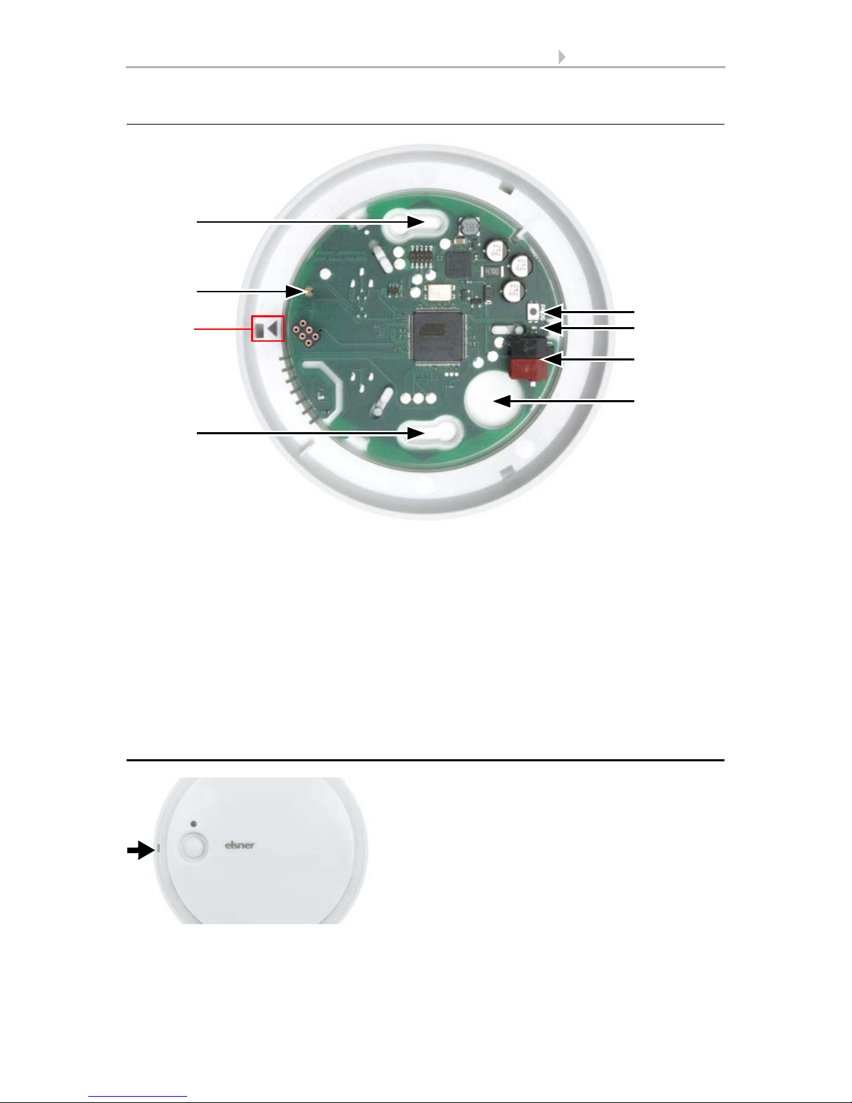
2.3.1. Housing from the outside
1
Fig. 1
1 Brightness sensors
A Recess to open the housing. When closing the housing, the recess aligns to the mark-
ing on the skirting
A
Page 8
6 Installation and start-up
Sensor Sewi KNX L • Version: 10.09.2018 • Technical Changes and Errors excepted.
2.3.2. Printed circuit boards / connections
2.4. Assembly
Fig. 2
1 a+b Long holes for mounting (hole distance 60 mm)
2 Brightness sensor
3 Programming button
4 Programming LED
5KNX-terminal BUS +/6 Cable bushing
A Mark for aligning the cover
1a
A
1b
3
5
6
4
2
Fig. 3
Open the housing. To do this, carefully lift the
cover from the skirting. Start at the recess
(Fig. 1: A).
Page 9

7 Installation and start-up
Sensor Sewi KNX L • Version: 10.09.2018 • Technical Changes and Errors excepted.
2.5. Notes on mounting and commissioning
Never expose the device to water (e.g. rain) or dust. This can damage the electronics.
You must not exceed a relative humidity of 95%. Avoid condensation.
The brightness sensor must not be painted over or covered.
After the bus voltage has been applied, the device will enter an initialisation phase lasting a few seconds. During this phase no information can be received or sent via the
bus.
Fig. 4
Lead the bus cable through the cable bushing
in the skirting.
Fig. 5
Screw the skirting to the wall or the ceiling.
Hole distance 60 mm.
60 mm
Fig. 6
Connect the KNX bus to the KNX terminal.
Fig. 7
Close the housing by positioning the cover
and snapping it into place. To do this, align
the recess on the cover to the marking on the
skirting (Fig. 1+2: A).
Page 10

8 Addressing the equipment
Sensor Sewi KNX L • Version: 10.09.2018 • Technical Changes and Errors excepted.
3. Addressing the equipment
The equipment is delivered with the bus address 15.15.255. You can program a different address in the ETS by overwriting the address 15.15.255 or by teaching the device
via the programming button.
The programming button is on the inside of the housing (Fig. 2: No. 3).
4. Maintenance
The brightness sensor must not get dirty over or covered. As a rule, it is sufficient to
wipe the device with a soft, dry cloth twice a year.
Page 11

9 Transfer protocol
Sensor Sewi KNX L • Version: 10.09.2018 • Technical Changes and Errors excepted.
5. Transfer protocol
Units:
Brightness in Lux
5.1. List of all communication objects
Abbreviation flags:
C Communication
R Read
WWrite
T Transfer
UUpdate
No. Text Func-
tion
Flags DPT type Size
1 Software version Output R-CT [217.1] DPT_Ver-
sion
2 bytes
96 Brightness measurement Output R-CT [9.4] DPT_Val-
ue_Lux
2 bytes
99 Brightness correction factor Input/
Output
RWCT [14.5] DPT_Val-
ue_Amplitude
4 bytes
129 Brightness sensor 2 threshold
value 1: Absolute value
Input/
Output
RWCT [9.4] DPT_Val-
ue_Lux
2 bytes
130 Brightness sensor 2 threshold
value 1: (1:+ | 0:-)
Input -WC- [1.1] DPT_Switch 1 bit
131 Brightness sensor 2 threshold
value 1: Delay from 0 to 1
Input -WC- [7.5] DPT_Time-
PeriodSec
2 bytes
132 Brightness sensor 2 threshold
value 1: Delay from 1 to 0
Input -WC- [7.5] DPT_Time-
PeriodSec
2 bytes
133 Brightness sensor 2 threshold
value 1: Switching output
Output R-CT [1.1] DPT_Switch 1 bit
134 Brightness sensor 2 threshold
value 1: Switching output block
Input -WC- [1.1] DPT_Switch 1 bit
136 Brightness sensor 2 threshold
value 2: Absolute value
Input/
Output
RWCT [9.4] DPT_Val-
ue_Lux
2 bytes
137 Brightness sensor 2 threshold
value 2: (1:+ | 0:-)
Input -WC- [1.1] DPT_Switch 1 bit
138 Brightness sensor 2 threshold
value 2: Delay from 0 to 1
Input -WC- [7.5] DPT_Time-
PeriodSec
2 bytes
139 Brightness sensor 2 threshold
value 2: Delay from 1 to 0
Input -WC- [7.5] DPT_Time-
PeriodSec
2 bytes
140 Brightness sensor 2 threshold
value 2: Switching output
Output R-CT [1.1] DPT_Switch 1 bit
Page 12

10 Transfer protocol
Sensor Sewi KNX L • Version: 10.09.2018 • Technical Changes and Errors excepted.
141 Brightness sensor 2 threshold
value 2: Switching output block
Input -WC- [1.1] DPT_Switch 1 bit
143 Brightness sensor 2 threshold
value 3: Absolute value
Input/
Output
RWCT [9.4] DPT_Val-
ue_Lux
2 bytes
144 Brightness sensor 2 threshold
value 3: (1:+ | 0:-)
Input -WC- [1.1] DPT_Switch 1 bit
145 Brightness sensor 2 threshold
value 3: Delay from 0 to 1
Input -WC- [7.5] DPT_Time-
PeriodSec
2 bytes
146 Brightness sensor 2 threshold
value 3: Delay from 1 to 0
Input -WC- [7.5] DPT_Time-
PeriodSec
2 bytes
147 Brightness sensor 2 threshold
value 3: Switching output
Output R-CT [1.1] DPT_Switch 1 bit
148 Brightness sensor 2 threshold
value 3: Switching output block
Input -WC- [1.1] DPT_Switch 1 bit
150 Brightness sensor 2 threshold
value 4: Absolute value
Input/
Output
RWCT [9.4] DPT_Val-
ue_Lux
2 bytes
151 Brightness sensor 2 threshold
value 4: (1:+ | 0:-)
Input -WC- [1.1] DPT_Switch 1 bit
152 Brightness sensor 2 threshold
value 4: Delay from 0 to 1
Input -WC- [7.5] DPT_Time-
PeriodSec
2 bytes
153 Brightness sensor 2 threshold
value 4: Delay from 1 to 0
Input -WC- [7.5] DPT_Time-
PeriodSec
2 bytes
154 Brightness sensor 2 threshold
value 4: Switching output
Output R-CT [1.1] DPT_Switch 1 bit
155 Brightness sensor 2 threshold
value 4: Switching output block
Input -WC- [1.1] DPT_Switch 1 bit
251 Night: Switching output Output R-CT [1.1] DPT_Switch 1 bit
252 Night: Switching delay on night Input -WC- [7,005] DPT_-
TimePeriodSec
2 bytes
253 Night: Switching delay on day Input -WC- [7,005] DPT_-
TimePeriodSec
2 bytes
1141 Computer 1: Input I1 Input RWCT Depending on
setting
4 bytes
1142 Computer 1: Input I2 Input RWCT Depending on
setting
4 bytes
1143 Computer 1: Input I3 Input RWCT Depending on
setting
4 bytes
1144 Computer 1: Output O1 Output R-CT Depending on
setting
4 bytes
1145 Computer 1: Output O2 Output R-CT Depending on
setting
4 bytes
1146 Computer 1: Condition text Output R-CT [16.0]
DPT_String_ASCII
14
bytes
No. Text Func-
tion
Flags DPT type Size
Page 13

11 Transfer protocol
Sensor Sewi KNX L • Version: 10.09.2018 • Technical Changes and Errors excepted.
1147 Computer 1: Monitoring status Output R-CT [1.1] DPT_Switch 1 bit
1148 Computer 1: Block (1: block) Input -WC- [1.1] DPT_Switch 1 bit
1149 Computer 2: Input I1 Input RWCT Depending on
setting
4 bytes
1150 Computer 2: Input I2 Input RWCT Depending on
setting
4 bytes
1151 Computer 2: Input I3 Input RWCT Depending on
setting
4 bytes
1152 Computer 2: Output O1 Output R-CT Depending on
setting
4 bytes
1153 Computer 2: Output O2 Output R-CT Depending on
setting
4 bytes
1154 Computer 2: Condition text Output R-CT [16.0]
DPT_String_ASCII
14
bytes
1155 Computer 2: Monitoring status Output R-CT [1.1] DPT_Switch 1 bit
1156 Computer 2: Block (1: block) Input -WC- [1.1] DPT_Switch 1 bit
1157 Computer 3: Input I1 Input RWCT Depending on
setting
4 bytes
1158 Computer 3: Input I2 Input RWCT Depending on
setting
4 bytes
1159 Computer 3: Input I3 Input RWCT Depending on
setting
4 bytes
1160 Computer 3: Output O1 Output R-CT Depending on
setting
4 bytes
1161 Computer 3: Output O2 Output R-CT Depending on
setting
4 bytes
1162 Computer 3: Condition text Output R-CT [16.0]
DPT_String_ASCII
14
bytes
1163 Computer 3: Monitoring status Output R-CT [1.1] DPT_Switch 1 bit
1164 Computer 3: Block (1: block) Input -WC- [1.1] DPT_Switch 1 bit
1165 Computer 4: Input I1 Input RWCT Depending on
setting
4 bytes
1166 Computer 4: Input I2 Input RWCT Depending on
setting
4 bytes
1167 Computer 4: Input I3 Input RWCT Depending on
setting
4 bytes
1168 Computer 4: Output O1 Output R-CT Depending on
setting
4 bytes
1169 Computer 4: Output O2 Output R-CT Depending on
setting
4 bytes
1170 Computer 4: Condition text Output R-CT [16.0]
DPT_String_ASCII
14
bytes
1171 Computer 4: Monitoring status Output R-CT [1.1] DPT_Switch 1 bit
No. Text Func-
tion
Flags DPT type Size
Page 14

12 Transfer protocol
Sensor Sewi KNX L • Version: 10.09.2018 • Technical Changes and Errors excepted.
1172 Computer 4: Block (1: block) Input -WC- [1.1] DPT_Switch 1 bit
1173 Computer 5: Input I1 Input RWCT Depending on
setting
4 bytes
1174 Computer 5: Input I2 Input RWCT Depending on
setting
4 bytes
1175 Computer 5: Input I3 Input RWCT Depending on
setting
4 bytes
1176 Computer 5: Output O1 Output R-CT Depending on
setting
4 bytes
1177 Computer 5: Output O2 Output R-CT Depending on
setting
4 bytes
1178 Computer 5: Condition text Output R-CT [16.0]
DPT_String_ASCII
14
bytes
1179 Computer 5: Monitoring status Output R-CT [1.1] DPT_Switch 1 bit
1180 Computer 5: Block (1: block) Input -WC- [1.1] DPT_Switch 1 bit
1181 Computer 6: Input I1 Input RWCT Depending on
setting
4 bytes
1182 Computer 6: Input I2 Input RWCT Depending on
setting
4 bytes
1183 Computer 6: Input I3 Input RWCT Depending on
setting
4 bytes
1184 Computer 6: Output O1 Output R-CT Depending on
setting
4 bytes
1185 Computer 6: Output O2 Output R-CT Depending on
setting
4 bytes
1186 Computer 6: Condition text Output R-CT [16.0]
DPT_String_ASCII
14
bytes
1187 Computer 6: Monitoring status Output R-CT [1.1] DPT_Switch 1 bit
1188 Computer 6: Block (1: block) Input -WC- [1.1] DPT_Switch 1 bit
1189 Computer 7: Input I1 Input RWCT Depending on
setting
4 bytes
1190 Computer 7: Input I2 Input RWCT Depending on
setting
4 bytes
1191 Computer 7: Input I3 Input RWCT Depending on
setting
4 bytes
1192 Computer 7: Output O1 Output R-CT Depending on
setting
4 bytes
1193 Computer 7: Output O2 Output R-CT Depending on
setting
4 bytes
1194 Computer 7: Condition text Output R-CT [16.0]
DPT_String_ASCII
14
bytes
1195 Computer 7: Monitoring status Output R-CT [1.1] DPT_Switch 1 bit
1196 Computer 7: Block (1: block) Input -WC- [1.1] DPT_Switch 1 bit
No. Text Func-
tion
Flags DPT type Size
Page 15

13 Transfer protocol
Sensor Sewi KNX L • Version: 10.09.2018 • Technical Changes and Errors excepted.
1197 Computer 8: Input I1 Input RWCT Depending on
setting
4 bytes
1198 Computer 8: Input I2 Input RWCT Depending on
setting
4 bytes
1199 Computer 8: Input I3 Input RWCT Depending on
setting
4 bytes
1200 Computer 8: Output O1 Output R-CT Depending on
setting
4 bytes
1201 Computer 8: Output O2 Output R-CT Depending on
setting
4 bytes
1202 Computer 8: Condition text Output R-CT [16.0]
DPT_String_ASCII
14
bytes
1203 Computer 8: Monitoring status Output R-CT [1.1] DPT_Switch 1 bit
1204 Computer 8: Block (1: block) Input -WC- [1.1] DPT_Switch 1 bit
1391 Logic input 1 Input -WC- [1.2] DPT_Bool 1 bit
1392 Logic input 2 Input -WC- [1.2] DPT_Bool 1 bit
1393 Logic input 3 Input -WC- [1.2] DPT_Bool 1 bit
1394 Logic input 4 Input -WC- [1.2] DPT_Bool 1 bit
1395 Logic input 5 Input -WC- [1.2] DPT_Bool 1 bit
1396 Logic input 6 Input -WC- [1.2] DPT_Bool 1 bit
1397 Logic input 7 Input -WC- [1.2] DPT_Bool 1 bit
1398 Logic input 8 Input -WC- [1.2] DPT_Bool 1 bit
1399 Logic input 9 Input -WC- [1.2] DPT_Bool 1 bit
1400 Logic input 10 Input -WC- [1.2] DPT_Bool 1 bit
1401 Logic input 11 Input -WC- [1.2] DPT_Bool 1 bit
1402 Logic input 12 Input -WC- [1.2] DPT_Bool 1 bit
1403 Logic input 13 Input -WC- [1.2] DPT_Bool 1 bit
1404 Logic input 14 Input -WC- [1.2] DPT_Bool 1 bit
1405 Logic input 15 Input -WC- [1.2] DPT_Bool 1 bit
1406 Logic input 16 Input -WC- [1.2] DPT_Bool 1 bit
1411 AND logic 1: 1-bit switching output Output R-CT [1.2] DPT_Bool 1 bit
1412 AND logic 1: 8-bit output A Output R-CT [5.010] DPT_-
Value_1_Ucount
1 byte
1413 AND logic 1: 8-bit output B Output R-CT [5.010] DPT_-
Value_1_Ucount
1 byte
1414 AND logic 1: Block Input -WC- [1.1] DPT_Switch 1 bit
1415 AND logic 2: 1-bit switching output Output R-CT [1.2] DPT_Bool 1 bit
1416 AND logic 2: 8-bit output A Output R-CT [5.010] DPT_-
Value_1_Ucount
1 byte
1417 AND logic 2: 8-bit output B Output R-CT [5.010] DPT_-
Value_1_Ucount
1 byte
No. Text Func-
tion
Flags DPT type Size
Page 16

14 Transfer protocol
Sensor Sewi KNX L • Version: 10.09.2018 • Technical Changes and Errors excepted.
1418 AND logic 2: Block Input -WC- [1.1] DPT_Switch 1 bit
1419 AND logic 3: 1-bit switching output Output R-CT [1.2] DPT_Bool 1 bit
1420 AND logic 3: 8-bit output A Output R-CT [5.010] DPT_-
Value_1_Ucount
1 byte
1421 AND logic 3: 8-bit output B Output R-CT [5.010] DPT_-
Value_1_Ucount
1 byte
1422 AND logic 3: Block Input -WC- [1.1] DPT_Switch 1 bit
1423 AND logic 4: 1-bit switching output Output R-CT [1.2] DPT_Bool 1 bit
1424 AND logic 4: 8-bit output A Output R-CT [5.010] DPT_-
Value_1_Ucount
1 byte
1425 AND logic 4: 8-bit output B Output R-CT [5.010] DPT_-
Value_1_Ucount
1 byte
1426 AND logic 4: Block Input -WC- [1.1] DPT_Switch 1 bit
1427 AND logic 5: 1-bit switching output Output R-CT [1.2] DPT_Bool 1 bit
1428 AND logic 5: 8-bit output A Output R-CT [5.010] DPT_-
Value_1_Ucount
1 byte
1429 AND logic 5: 8-bit output B Output R-CT [5.010] DPT_-
Value_1_Ucount
1 byte
1430 AND logic 5: Block Input -WC- [1.1] DPT_Switch 1 bit
1431 AND logic 6: 1-bit switching output Output R-CT [1.2] DPT_Bool 1 bit
1432 AND logic 6: 8-bit output A Output R-CT [5.010] DPT_-
Value_1_Ucount
1 byte
1433 AND logic 6: 8-bit output B Output R-CT [5.010] DPT_-
Value_1_Ucount
1 byte
1434 AND logic 6: Block Input -WC- [1.1] DPT_Switch 1 bit
1435 AND logic 7: 1-bit switching output Output R-CT [1.2] DPT_Bool 1 bit
1436 AND logic 7: 8-bit output A Output R-CT [5.010] DPT_-
Value_1_Ucount
1 byte
1437 AND logic 7: 8-bit output B Output R-CT [5.010] DPT_-
Value_1_Ucount
1 byte
1438 AND logic 7: Block Input -WC- [1.1] DPT_Switch 1 bit
1439 AND logic 8: 1-bit switching output Output R-CT [1.2] DPT_Bool 1 bit
1440 AND logic 8: 8-bit output A Output R-CT [5.010] DPT_-
Value_1_Ucount
1 byte
1441 AND logic 8: 8-bit output B Output R-CT [5.010] DPT_-
Value_1_Ucount
1 byte
1442 AND logic 8: Block Input -WC- [1.1] DPT_Switch 1 bit
1443 OR logic 1: 1-bit switching output Output R-CT [1.2] DPT_Bool 1 bit
1444 OR logic 1: 8-bit output A Output R-CT [5.010] DPT_-
Value_1_Ucount
1 byte
1445 OR logic 1: 8-bit output B Output R-CT [5.010] DPT_-
Value_1_Ucount
1 byte
No. Text Func-
tion
Flags DPT type Size
Page 17

15 Transfer protocol
Sensor Sewi KNX L • Version: 10.09.2018 • Technical Changes and Errors excepted.
1446 OR logic 1: Block Input -WC- [1.1] DPT_Switch 1 bit
1447 OR logic 2: 1-bit switching output Output R-CT [1.2] DPT_Bool 1 bit
1448 OR logic 2: 8-bit output A Output R-CT [5.010] DPT_-
Value_1_Ucount
1 byte
1449 OR logic 2: 8-bit output B Output R-CT [5.010] DPT_-
Value_1_Ucount
1 byte
1450 OR logic 2: Block Input -WC- [1.1] DPT_Switch 1 bit
1451 OR logic 3: 1-bit switching output Output R-CT [1.2] DPT_Bool 1 bit
1452 OR logic 3: 8-bit output A Output R-CT [5.010] DPT_-
Value_1_Ucount
1 byte
1453 OR logic 3: 8-bit output B Output R-CT [5.010] DPT_-
Value_1_Ucount
1 byte
1454 OR logic 3: Block Input -WC- [1.1] DPT_Switch 1 bit
1455 OR logic 4: 1-bit switching output Output R-CT [1.2] DPT_Bool 1 bit
1456 OR logic 4: 8-bit output A Output R-CT [5.010] DPT_-
Value_1_Ucount
1 byte
1457 OR logic 4: 8-bit output B Output R-CT [5.010] DPT_-
Value_1_Ucount
1 byte
1458 OR logic 4: Block Input -WC- [1.1] DPT_Switch 1 bit
1459 OR logic 5: 1-bit switching output Output R-CT [1.2] DPT_Bool 1 bit
1460 OR logic 5: 8-bit output A Output R-CT [5.010] DPT_-
Value_1_Ucount
1 byte
1461 OR logic 5: 8-bit output B Output R-CT [5.010] DPT_-
Value_1_Ucount
1 byte
1462 OR logic 5: Block Input -WC- [1.1] DPT_Switch 1 bit
1463 OR logic 6: 1-bit switching output Output R-CT [1.2] DPT_Bool 1 bit
1464 OR logic 6: 8-bit output A Output R-CT [5.010] DPT_-
Value_1_Ucount
1 byte
1465 OR logic 6: 8-bit output B Output R-CT [5.010] DPT_-
Value_1_Ucount
1 byte
1466 OR logic 6: Block Input -WC- [1.1] DPT_Switch 1 bit
1467 OR logic 7: 1-bit switching output Output R-CT [1.2] DPT_Bool 1 bit
1468 OR logic 7: 8-bit output A Output R-CT [5.010] DPT_-
Value_1_Ucount
1 byte
1469 OR logic 7: 8-bit output B Output R-CT [5.010] DPT_-
Value_1_Ucount
1 byte
1470 OR logic 7: Block Input -WC- [1.1] DPT_Switch 1 bit
1471 OR logic 8: 1-bit switching output Output R-CT [1.2] DPT_Bool 1 bit
1472 OR logic 8: 8-bit output A Output R-CT [5.010] DPT_-
Value_1_Ucount
1 byte
1473 OR logic 8: 8-bit output B Output R-CT [5.010] DPT_-
Value_1_Ucount
1 byte
No. Text Func-
tion
Flags DPT type Size
Page 18

16 Parameter setting
Sensor Sewi KNX L • Version: 10.09.2018 • Technical Changes and Errors excepted.
6. Parameter setting
6.1. Behaviour on power failure/ restoration of
power
Behaviour following a failure of the bus power supply:
The device sends nothing.
Behaviour on bus restoration of power and following programming or reset:
The device sends all outputs according to their send behaviour set in the parameters
with the delays established in the "General settings" parameter block.
1474 OR logic 8: Block Input -WC- [1.1] DPT_Switch 1 bit
1581 Light controller: Brightness setpoint
value
Input/
Output
RWCT [9.4] DPT_Val-
ue_Lux
2 bytes
1582 Light controller: Stop delay Input/
Output
RWCT [7.5] DPT_Time-
PeriodSec
2 bytes
1583 Light controller: Start / Stop (1 = Start
| 0 = Stop)
Input -WC- [1.1] DPT_Switch 1 bit
1584 Light controller: Dimmer increments Input RWCT [5.1] DPT_Scaling 1 byte
1586 Light controller: Target-actual-
difference
Input/
Output
RWCT [9.4] DPT_Val-
ue_Lux
2 bytes
1587 Light controller: Reset time Input/
Output
RWCT [7.5] DPT_Time-
PeriodSec
2 bytes
1588 Light controller: Actuating variable Input/
Output
R-CT [5.1] DPT_Scaling 1 byte
1589 Light controller: Switching Output R-CT [1.1] DPT_Switch 1 bit
1590 Light controller: Dimming Output R-CT [3.7] DPT_Con-
trol_Dimming
4 bit
1591 Light controller: Brightness in % Output R-CT [5.1] DPT_Scaling 1 byte
1592 Light controller: Switching feedback Input -WC- [1.1] DPT_Switch 1 bit
1593 Light controller: Dim response Input -WC- [3.7] DPT_Con-
trol_Dimming
4 bit
1594 Light controller: Brightness in %
response
Input -WCT [5.1] DPT_Scaling 1 byte
1595 Light controller: Interruption waiting
period
Input/
Output
RWCT [7.5] DPT_Time-
PeriodSec
2 bytes
1596 Light controller: Continued Input -WC- [1.1] DPT_Switch 1 bit
1597 Light controller: Block (1 = Blocking) Input -WC- [1.1] DPT_Switch 1 bit
No. Text Func-
tion
Flags DPT type Size
Page 19

17 Parameter setting
Sensor Sewi KNX L • Version: 10.09.2018 • Technical Changes and Errors excepted.
6.2. General settings
Set basic characteristics for the data transfer.
6.3. Light control
For light control, the Sensor Sewi KNX L detects the brightness in the room.
Activate the light control.
Set, in which cases the data received via object for setpoint value, setpoint value-actual difference, dimming increment and times are to be retained. Please note that the
setting "After power supply restoration and programming" should not be used for the
initial start-up, as the factory settings are always used until the first communication.
Set the setpoint value for the brightness in the room and specify whether, besides the dimming information defined below, a switching object should also be sent.
With Sensor Sewi KNX L, the regulation is always started or stopped by an object.
Set the object evaluation and the object value prior to the first communication.
At the end of the regulation, either "nothing"(status remains unchanged), an on or off
command (via the activated switching object) or a dim value can be sent.
Send delay after power-up and programming for:
Measured values 5 s • ... • 2 h
Threshold values and switching outputs 5 s • ... • 2 h
Computer objects 5 s • ... • 2 h
Logic objects 5 s • ... • 2 h
Maximum telegram rate • 1 message per second
• ...
• 5 messages per second
• ...
• 20 messages per second
Use control No • Yes
Maintain the
data received via object setpoint value,
setpoint value-actual difference, dimming
increment and times
• never
• after power supply restoration
• after power supply restoration and
programming
Setpoint value in Lux 0...60000; 500
Send switching object No • Yes
Regulation starts on Reception of a start/stop-object
Regulation stops on Reception of a start/stop-object
Page 20

18 Parameter setting
Sensor Sewi KNX L • Version: 10.09.2018 • Technical Changes and Errors excepted.
Set, at which deviation from the setpoint value a dim command is to be sent. Specify the dimming increment and the repetition cycle for the dim command.
Define, up to which response value the dim actuator sends a brighter or darker command. On the one hand, this defines the range of use for the lamp, on the other hand,
once the minimum or maximum value has been reached, no unnecessary messages
are sent to the bus.
The light regulation can be interrupted during switching or dimming by response
objects, i.e. nothing else is transmitted via the dim output. This results in manual light
operation having priority.
Set, which objects will trigger interruption and when the regulation is to be continued.
Object evaluation • 1 = start | 0 = stop
• 0 = start | 1 = stop
Object value prior to first communication 0 • 1
Reaction to stop • send nothing
• send off command
• send on command
• send value
Value in % 0...100
Send the dim command, if • the actual value deviates from the set-
point value by more than X%
• the actual value deviates from the set-
point value by more than X Lux
Target / actual difference in %
(for a deviation in %)
1...100; 20
Target / actual difference in Lux
(for a deviation in Lux)
1...2500; 100
Dimmer increments 100.00% • 50.00% • 25.00% • 12.5% • 6.25% •
3.13% • 1.56%
Repetition of the dim command in seconds 1...600; 6
Dim brighter with response value in % 1...100
Dim darker with response value in % 0...99
Use interruptions No • Yes
Interrupt regulation when
Reception from response switching object No • Yes
Reception from response dimming object No • Yes
Continue regulation • after a waiting period
• at object reception after waiting period
• at object reception or after waiting period
Waiting period in seconds 5...72000 (Standard value depending on the
setting of "continue regulation")
Object value 0 • 1 • 0 or 1
Page 21

19 Parameter setting
Sensor Sewi KNX L • Version: 10.09.2018 • Technical Changes and Errors excepted.
Note: If the criteria for the continuation of the regulation are fulfilled, the regulation,
however, has just been stopped by an object or is blocked, then the end of the interruption has no effect on the behaviour of the light.
The light regulation can be blocked via the bus. In contrast to the interruption, when
blocking, a switching command or brightness value can be sent. The output behaviour
follows the rule upon release.
6.4. Brightness Measurement
The Sensor Sewi KNX L detects the brightness in rooms, for example for controlling
lights.
Set the sending pattern for the measured brightness.
The brightness reading can be corrected in order to compensate for a dull or bright
point of installation for the sensor.
Set, in which cases the correction factor received via object is to be retained. Please
note that the setting "After power supply restoration and programming" should not be
used for the initial start-up, as the factory settings are always used until the first communication (setting via objects is ignored).
Specify the starting correction factor.
Use block No • Yes
Analysis of the blocking object • at value 1: block | at value 0: release
• at value 0: block | at value 1: release
Value prior to initial communication 0 • 1
Output pattern
On block • send nothing
• send off command
• send on command
• send value
Sending pattern • never
• periodically
• on change
• on change and periodically
at and above change in %
(if sent on change)
1 ... 100; 20
Send cycle
(if sent periodically)
5 s ... 2 h
Use reading correction No • Yes
Maintain the
correction factor received via
communication object
• never
• after power supply restoration
• after power supply restoration and
programming
Page 22

20 Parameter setting
Sensor Sewi KNX L • Version: 10.09.2018 • Technical Changes and Errors excepted.
Examples:
For a factor of 1.234 the parameter value is 1234.
For a factor of 0.789 the parameter value is 789.
For a factor of 1.2 and a reading of 1000 Lux the transmitted value is 1200 Lux.
6.5. Brightness threshold values
Activate the required brightness threshold value. The menus for setting the threshold
values are displayed.
6.5.1. Threshold value 1/2/3/4
Threshold value
Set, in which cases threshold values and delay times received are to be kept per object.
The parameter is only taken into consideration if the specification/ setting by object is
activated further down. Please note that the setting "After power restoration and programming" should not be used for the initial start-up, as the factory settings are always
used until the first call (setting via objects is ignored).
Select whether the threshold value is to be specified per parameter or via a communication object.
When the threshold value per parameter is specified, then the value is set.
When the threshold value per communication object is specified, the starting
value, object value limit and type of change to the threshold value are then set.
Start correction factor in 0.001
valid till first communication
1 ... 10000; 1000
Threshold value 1/2/3/4 No • Yes
Maintain the
threshold values and delays received via
communication objects
• never
• after power supply restoration
• after power supply restoration and
programming
Threshold value setpoint using Parameter • Communications object
Threshold value in kLux 1000 … 150000; 60000
Start threshold value in Lux
valid until first call
1000 … 150000; 60000
Object value limit (min.) in Lux 1000 … 150000
Object value limit (max.) in Lux 1000 … 150000
Page 23

21 Parameter setting
Sensor Sewi KNX L • Version: 10.09.2018 • Technical Changes and Errors excepted.
With both of the methods for specifying the threshold values the hysteresis is set.
Switching output
Define which value the output transmits if the threshold value is exceeded or undercut.
Set the delay for the switching and in which cases the switch output transmits.
Block
If necessary, activate the switching output block and set what a 1 or 0 at the block entry
means and what happens in the event of a block.
Type of threshold change Absolute value • Increase/decrease
Increment in Lux
(upon increase/decrease change)
1000 • 2000 • 5000 • 10000 • 20000
Hysteresis setting in % • absolute
Hysteresis in % of the threshold value
(for setting in %)
0 … 100; 50
Hysteresis in Lux
(for absolute setting)
0 … 150000; 30000
When the following conditions apply, the
output is
(LV = Threshold value)
• GW above = 1 | GW - Hyst. below = 0
• GW above = 0 | GW - Hyst. below = 1
• GW below = 1 | GW + Hyst. above = 0
• GW below = 0 | GW + Hyst. above = 1
Delays can be set via objects
(in seconds)
No • Yes
Delay from 0 to 1 none • 1 s … 2 h
Delay from 1 to 0 none • 1 s … 2 h
Switching output sends • on change
• on change to 1
• on change to 0
• on change and periodically
• on change to 1 and periodically
• on change to 0 and periodically
Cycle
(if sent periodically)
5 s ... 2 h
Use switching output block No • Yes
Analysis of the blocking object • At value 1: block | At value 0: release
• At value 0: block | At value 1: release
Blocking object value before first call 0 • 1
Action when locking • Do not send message
• send 0
• send 1
Action upon release
(with 2 seconds release delay)
[Dependent on the "Switching output
sends" setting]
Page 24

22 Parameter setting
Sensor Sewi KNX L • Version: 10.09.2018 • Technical Changes and Errors excepted.
The behaviour of the switching output on release is dependent on the value of the parameter "Switching output sends" (see "Switching output")
6.6. Night
If necessary, activate the night recognition.
Set, in which cases delay times received are to be kept per object. The parameter is
only taken into consideration if the setting by object is activated further down. Please
note that the setting "After power restoration and programming" should not be used
for the initial start-up, as the factory settings are always used until the first call (setting
via objects is ignored).
Specify below which brightness the device should recognise "night" and with which
hysteresis this is to be outputted.
Set the delay for the switching and in which cases the switch output sends and which
value is output at night.
Switching output sends on change do not send message •
Status object/s send/s
Switching output sends on change to 1 do not send message •
If switching output = 1 send 1
Switching output sends on change to 0 do not send message •
If switching output = 0 send 0
Switching output sends on change and
periodically
Send switching output status
Switching output sends on change to 1 and
periodically
If switching output = 1 send 1
Switching output sends on change to 0 and
periodically
If switching output = 0 send 0
Use night recognition No • Yes
Maintain the
delays received via communication objects • never
• after power supply restoration
• after power supply restoration and
programming
Night is recognised below
Lux
1 ... 1000; 10
Hysteresis in Lux 0 ... 500; 5
Delays can be set via objects
(in seconds)
No • Yes
Switching delay on night none • 1 s … 2 h
Switching delay on day none • 1 s … 2 h
Page 25

23 Parameter setting
Sensor Sewi KNX L • Version: 10.09.2018 • Technical Changes and Errors excepted.
6.7. Computer
Activate the multi-functional computer, with which the input data can be changed by
calculation, querying a condition or converting the data point type. The menus for the
further setting of the computer are then displayed.
6.7.1. Computer 1-8
Set, in which cases input values received are to be kept per object. Please note that the
setting "After power restoration and programming" should not be used for the initial
start-up, as the factory settings are always used until the first call (setting via objects is
ignored).
Switching output sends • on change
• on change to night
• on change to day
• on change and periodically
• on change to night and periodically
• on change to day and periodically
Send cycle
(if sent periodically)
5 s ... 2 h
Object value at night 0 • 1
Computer 1/2/3/4/5/6/7/8 No • Yes
Maintain the
input values received via communication
objects
• never
• after power supply restoration
• after power supply restoration and
programming
Page 26

24 Parameter setting
Sensor Sewi KNX L • Version: 10.09.2018 • Technical Changes and Errors excepted.
Select the function set the input mode and starting values for input 1 and input 2.
Prerequisites
When querying the prerequisites set the output type and output values at different statuses:
Function (I = Input) • Prerequisite: E1 = E2
• Prerequisite: E1 > E2
• Prerequisite: E1 >= E2
• Prerequisite: E1 < E2
• Prerequisite: E1 <= E2
• Prerequisite: E1 - E2 >= E3
• Prerequisite: E2 - E1 >= E3
• Prerequisite: E1 - E2 amount >= E3
• Calculation: E1 + E2
• Calculation: E1 - E2
• Calculation: E2 - E1
• Calculation: E1 - E2 Amount
• Calculation: Output 1 = E1 × X + Y |
Output 2 = E2 × X + Y |
• Transformation: General
Tolerance for comparison
(in the case of prerequisite E1 = E2)
0 ... 4,294,967,295
Input type [Selection options depending on the func-
tion]
• 1 bit
• 1 byte (0...255)
• 1 byte (0%...100%)
• 1 byte (0°...360°)
• 2 byte counter without math. symbol
• 2 byte counter with math. symbol
• 2 byte floating point
• 4 byte counter without math. symbol
• 4 byte counter with math. symbol
• 4 byte floating point
Starting value E1 / E2 / E3 [Input range depending on the type of
input]
Output type • 1 bit
• 1 byte (0...255)
• 1 byte (0%...100%)
• 1 byte (0°...360°)
• 2 byte counter without math. symbol
• 2 byte counter with math. symbol
• 2 byte floating point
• 4 byte counter without math. symbol
• 4 byte counter with math. symbol
• 4 byte floating point
Output value (if applicable output value A1 / A2)
Page 27

25 Parameter setting
Sensor Sewi KNX L • Version: 10.09.2018 • Technical Changes and Errors excepted.
Set the output send pattern.
Set the text to be displayed for conditions met / not met.
If applicable set the send delays.
Calculations and transformation
For calculations and transformations set the output values to the various conditions:
if the condition is met 0 [Input range depending on the type of
output]
if the condition is not met 0 [Input range depending on the type of
output]
if the monitoring time period
is exceeded
0 [Input range depending on the type of
output]
if blocked 0 [Input range depending on the type of
output]
Output sends • on change
• on change and after reset
• on change and periodically
• when receiving an input object
• when receiving an input object
and periodically
Type of change
(is only sent if "on change" is selected)
• on each change
• on change to condition met
• on change to condition not met
Send cycle
(if sent periodically)
5 s ... 2 h; 10 s
Text if the condition is met [Free text max. 14 chars.]
Text if the condition is not met [Free text max. 14 chars.]
Send delay in the event of change
to the condition is met
none • 1 s • ... • 2 h
Send delay in the event of change
to the condition is not met
none • 1 s • ... • 2 h
Output value (if applicable A1 / A2)
if the monitoring time period
is exceeded
0 [Input range depending on the type of
output]
if blocked 0 [Input range depending on the type of
output]
Page 28

26 Parameter setting
Sensor Sewi KNX L • Version: 10.09.2018 • Technical Changes and Errors excepted.
Set the output send pattern.
For Calculations of the form output 1 = E1 × X + Y | output 2 = E2 × X +Y define
the variables X and Y. The variables can have a positive or negative sign, 9 digits before
and 9 digits after the decimal point.
Further settings for all formulas
If necessary, activate the input monitoring. Set which inputs are to be monitored, at
which intervals the inputs are to be monitored and what value the "monitoring status"
should have, if the monitoring period is exceeded without feedback.
If necessary, activate the computer block and set what a 1 or 0 at the block entry means
and what happens in the event of a block.
Output sends • on change
• on change and after reset
• on change and periodically
• when receiving an input object
• when receiving an input object
and periodically
on change of
(only if calculations are
transmitted for changes)
1 ... [Input range depending on the type of
input]
Send cycle
(if sent periodically)
5 s ... 2 h; 10 s
Formula for output A1: A1 = E1 × X + Y
X1.00 [free input]
Y0.00 [free input]
Formula for output A2: A2 = E2 × X + Y
X1.00 [free input]
Y0.00 [free input]
Use input monitoring No • Yes
Monitoring of • E1
• E2
• E3
• E1 and E2
• E1 and E3
• E2 and E3
• E1 and E2 and E3
[depending on the function]
Monitoring period 5 s • ... • 2 h; 1 min
Value of the object "monitoring status"
if period is exceeded
0 • 1
Use block No • Yes
Analysis of the blocking object • At value 1: block | At value 0: release
• At value 0: block | At value 1: release
Page 29

27 Parameter setting
Sensor Sewi KNX L • Version: 10.09.2018 • Technical Changes and Errors excepted.
6.8. Logic
The device has 16 logic inputs, eight AND and eight OR logic gates.
Activate the logic inputs and assign object values up to first call.
Activate the required logic outputs.
AND logic
OR logic
6.8.1. AND logic 1-8 and OR logic outputs 1-8
The same setting options are available for AND and OR logic.
Each logic output may transmit one 1 bit or two 8 bit objects. Determine what the out
put should send if logic = 1 and = 0.
Value before first call 0 • 1
Output pattern
On block
• do not send anything
• send value
On release • as send pattern [see above]
• send current value immediately
Use logic inputs Yes • No
Object value prior to first call for:
- Logic input 1 0 • 1
- Logic input ... 0 • 1
- Logic input 16 0 • 1
AND logic 1 not active • active
AND logic ... not active • active
AND logic 8 not active • active
OR logic 1 not active • active
OR logic ... not active • active
OR logic 8 not active • active
Page 30

28 Parameter setting
Sensor Sewi KNX L • Version: 10.09.2018 • Technical Changes and Errors excepted.
If the output type is a 1-bit object, set the output values for the various conditions.
If the output type is two 8-bit objects, set the type of object and the output values
for the various conditions.
1. / 2. / 3. / 4. Input • do not use
- Logic inputs 1...16
- Logic inputs 1...16 inverted
• all switching events that the device
provides (see Connection inputs of the
AND/OR logic)
Output type • a 1-Bit-object
• two 8-bit objects
Output value
if logic = 1
1 • 0
Output value
if logic = 0
1 • 0
Output value
If block is active
1 • 0
Output value if
monitoring period is exceeded
1 • 0
Object type • Value (0…255)
• Percent (0…100%)
• Angle (0…360°)
• Scene call-up (0…127)
Output value object A
if logic = 1
0 … 255 / 100% / 360° / 127; 1
Output value object B
if logic = 1
0 … 255 / 100% / 360° / 127; 1
Output value object A
if logic = 0
0 … 255 / 100% / 360° / 127; 0
Output value object B
if logic = 0
0 … 255 / 100% / 360° / 127; 0
Output value object A
if block is active
0 … 255 / 100% / 360° / 127; 0
Output value object B
if block is active
0 … 255 / 100% / 360° / 127; 0
Output value object A if
monitoring period is exceeded
0 … 255 / 100% / 360° / 127; 0
Output value object B if
monitoring period is exceeded
0 … 255 / 100% / 360° / 127; 0
Page 31

29 Parameter setting
Sensor Sewi KNX L • Version: 10.09.2018 • Technical Changes and Errors excepted.
Set the output send pattern.
Block
If necessary, activate the block for the logic output and set what a 1 or 0 at the block
input means and what happens in the event of a block.
Monitoring
If necessary, activate the input monitoring. Set which inputs are to be monitored, at
which intervals the inputs are to be monitored and what value the "monitoring status"
should have, if the monitoring period is exceeded without a feedback being given.
6.8.2. AND logic connection inputs
Do not use
Send pattern • on change of logic
• on change of logic to 1
• on change of logic to 0
• on change of logic and periodically
• on change of logic to 1 and periodically
• on change of logic to 0 and periodically
• on change of logic+object receipt
• on change of logic+object receipt
and periodically
Send cycle
(if sent periodically)
5 s • 10 s • ... • 2 h
Use block No • Yes
Analysis of the blocking object • At value 1: block | At value 0: release
• At value 0: block | At value 1: release
Blocking object value before first call 0 • 1
Output pattern
On block
• Do not send message
• Transmit block value [see above,
Output value if blocking active]
On release
(with 2 seconds release delay)
[send value for current logic status]
Use input monitoring No • Yes
Input monitoring • 1 • 2 • 3 • 4
• 1 + 2 • 1 + 3 • 1 + 4 • 2 + 3 • 2 + 4 • 3 + 4
• 1 + 2 + 3 • 1 + 2 + 4 • 1 + 3 + 4 • 2 + 3 + 4
• 1 + 2 + 3 + 4
Monitoring period 5 s • ... • 2 h; 1 min
Output behaviour on exceeding the moni-
toring time
• Do not send message
• Send value exceeding [= value of the
parameter "monitoring period"]
Page 32

30 Parameter setting
Sensor Sewi KNX L • Version: 10.09.2018 • Technical Changes and Errors excepted.
Logic input 1
Logic input 1 inverted
Logic input 2
Logic input 2 inverted
Logic input 3
Logic input 3 inverted
Logic input 4
Logic input 4 inverted
Logic input 5
Logic input 5 inverted
Logic input 6
Logic input 6 inverted
Logic input 7
Logic input 7 inverted
Logic input 8
Logic input 8 inverted
Logic input 9
Logic input 9 inverted
Logic input 10
Logic input 10 inverted
Logic input 11
Logic input 11 inverted
Logic input 12
Logic input 12 inverted
Logic input 13
Logic input 13 inverted
Logic input 14
Logic input 14 inverted
Logic input 15
Logic input 15 inverted
Logic input 16
Logic input 16 inverted
Switching output night
Switching output night inverted
Brightness sensor switching output 1
Brightness sensor switching output 1 inverted
Brightness sensor switching output 2
Brightness sensor switching output 2 inverted
Brightness sensor switching output 3
Brightness sensor switching output 3 inverted
Brightness sensor switching output 4
Brightness sensor switching output 4 inverted
6.8.3. Connection inputs of the OR logic
The OR logic connection inputs correspond to those of the AND logic. In addition, the
following inputs are available for the OR logic:
Page 33

31 Parameter setting
Sensor Sewi KNX L • Version: 10.09.2018 • Technical Changes and Errors excepted.
Switching output AND logic 1
Switching output AND logic 1 inverted
Switching output AND logic 2
Switching output AND logic 2 inverted
Switching output AND logic 3
Switching output AND logic 3 inverted
Switching output AND logic 4
Switching output AND logic 4 inverted
Switching output AND logic 5
Switching output AND logic 5 inverted
Switching output AND logic 6
Switching output AND logic 6 inverted
Switching output AND logic 7
Switching output AND logic 7 inverted
Switching output AND logic 8
Switching output AND logic 8 inverted
Page 34

Elsner Elektronik GmbH Control and Automation Engineering
Sohlengrund 16
75395 Ostelsheim Phone +49 (0) 70 33 / 30 945-0 info@elsner-elektronik.de
Germany Fax +49 (0) 70 33 / 30 945-20 www.elsner-elektronik.de
Technical support: +49 (0) 70 33 / 30 945-250
 Loading...