

Page 1
EN
Sewi KNX AQS and
Sewi KNX AQS/TH-D
Indoor Air Quality Sensors
Item numbers 70394 (AQS), 70397 (AQS/TH-D)
Installation and Adjustment
Page 2

Page 3

1 Contents
1. Description ........................................................................................... 5
1.0.1. Scope of delivery .......................................................................................... 6
1.1. Technical data ........................................................................................................... 6
1.1.1. Measuring accuracy ...................................................................................... 7
2. Installation and start-up ....................................................................... 7
2.1. Installation notes ...................................................................................................... 7
2.2. Installation location .................................................................................................. 8
2.3. Construction of the sensor ...................................................................................... 9
2.3.1. Housing from the outside ............................................................................ 9
2.3.2. Printed circuit boards / connections .......................................................... 10
2.4. Assembly ................................................................................................................ 10
2.5. Notes on mounting and commissioning .............................................................. 11
3. Addressing the equipment ................................................................. 12
4. Maintenance ....................................................................................... 12
5. Transfer protocol ............................................................................... 13
5.1. List of all communication objects ......................................................................... 13
6. Parameter setting .............................................................................. 28
6.1. Behaviour on power failure/ restoration of power .............................................. 28
6.2. General settings ..................................................................................................... 29
6.3. Temperature Measurement ................................................................................... 29
6.4. Temperature threshold values .............................................................................. 30
6.4.1. Threshold value 1, 2, 3, 4 ........................................................................... 30
6.5. Temperature PI control .......................................................................................... 32
6.5.1. Heating control level 1/2 ............................................................................. 37
6.5.2. Cooling control level 1/2 ............................................................................. 40
6.6. Summer Compensation ......................................................................................... 42
6.7. Humidity Measurement ......................................................................................... 43
6.8. Humidity threshold values .................................................................................... 44
6.8.1. Threshold value 1, 2, 3, 4 ........................................................................... 44
6.9. Humidity PI control ................................................................................................ 46
6.10.Dewpoint measurement ........................................................................................ 49
6.10.1. Cooling medium temp. monitoring ........................................................... 49
6.11.Absolute humidity ................................................................................................. 51
6.12.Comfort field .......................................................................................................... 52
6.13.Air Pressure Measurement ................................................................................... 53
6.14.Air pressure threshold values ............................................................................... 54
6.14.1. Air pressure threshold value 1-4 ............................................................... 54
6.15.CO2 Measurement ................................................................................................. 57
6.16.CO2 threshold values ............................................................................................ 57
6.16.1. Threshold value 1, 2, 3, 4 ........................................................................... 57
6.17.CO2 PI-control ........................................................................................................ 60
6.18.Variable comparator .............................................................................................. 62
Elsner Elektronik GmbH • Sohlengrund 16 • 75395 Ostelsheim • Germany
Sensors Sewi KNX AQS and Sewi KNX AQS/TH-D • from ETS programme version 1.1
Version: 10.09.2018 • Technical changes and errors excepted.
Page 4

2 Contents
6.18.1. Control variable comparator 1/2/3/4 .......................................................... 62
6.19.Computer ................................................................................................................ 63
6.19.1. Computer 1-8 ............................................................................................... 63
6.20.Logic ........................................................................................................................ 67
6.20.1. AND logic 1-8 and OR logic outputs 1-8 ................................................... 67
6.20.2. AND logic connection inputs ..................................................................... 69
6.20.3. Connection inputs of the OR logic ............................................................. 72
Elsner Elektronik GmbH • Sohlengrund 16 • 75395 Ostelsheim • Germany
Sensors Sewi KNX AQS and Sewi KNX AQS/TH-D • from ETS programme version 1.1
Version: 10.09.2018 • Technical changes and errors excepted.
Page 5
3 Clarification of signs
Installation, inspection, commissioning and troubleshooting of the device
must only be carried out by a competent electrician.
This manual is amended periodically and will be brought into line with new software
releases. The change status (software version and date) can be found in the contents footer.
If you have a device with a later software version, please check
www.elsner-elektronik.de in the menu area "Service" to find out whether a more up-todate version of the manual is available.
Clarification of signs used in this manual
Safety advice.
Safety advice for working on electrical connections, components,
etc.
DANGER!
WARNING!
CAUTION!
ATTENTION!
ETS In the ETS tables, the parameter default settings are marked by
... indicates an immediately hazardous situation which will lead to
death or severe injuries if it is not avoided.
... indicates a potentially hazardous situation which may lead to
death or severe injuries if it is not avoided.
... indicates a potentially hazardous situation which may lead to
trivial or minor injuries if it is not avoided.
... indicates a situation which may lead to damage to property if it is
not avoided.
underlining.
Page 6

4 Clarification of signs
Page 7

5 Description
1. Description
The Sensors Sewi KNX AQS and Sewi KNX AQS/TH-D for the KNX bus system
measures the CO
Sewi KNX AQS/TH-D additionally measures the temperature, the air humidity and
the air pressure and calculates the dew-point. The sensor can output a warning to the
bus as soon as the comfort field, as per DIN 1946, is left.
Via the bus, the indoor sensors can receive external values and process it further with
its own data to a total value (mixed value, e.g. room average).
All measurement values can be used for the control of limit-dependent switching outputs. States can be linked via AND logic gates and OR logic gates. Multi-function modules change input data as required by means of calculations, querying a condition, or
converting the data point type. In addition, an integrated manipulated variable comparator can compare and output variables that were received via communication objects.
Integrated PI-controllers control ventilation (according to humidity or CO
tion) and heating/cooling (according to temperature).
Functions:
• Measuring the CO
The share of internal measurement value and external value can be set as a
percentage
• Threshold values can be adjusted per parameter or via communication
objects
• PI controller for ventilation according to CO
(one-stage) or Ventilate (one or two-stage)
• 8 AND and 8 OR logic gates, each with 4 inputs. All switching events as well
as 16 logic inputs in the form of communications objects can be used as inputs
for the logic gates. The output of each gate can be configured optionally as 1bit or 2 x 8-bit
• 8 multi-function modules (computers) for changing the input data by
calculations, by querying a condition or by converting the data point type
• 4 actuating variable comparators to output minimum, maximum or
average values. 5 inputs each for values received via communication objects
Additional functions Sewi KNX AQS/TH-D:
• Measuring the temperature and air humidity (relative, absolute), each with
mixed value calculation. The share of internal measurement value and
external value can be set as a percentage
• Bus message, whether the values for temperature and air humidity are within
the comfort field (DIN 1946). Dew point calculation
• Air pressure measurement. Output of the value as normal pressure and
optionally as barometric pressure
• PI-controller for heating (one or two-stage) and cooling (one or two-stage)
according to temperature. Regulation according to separate setpoints or basic
setpoint temperature
concentration in a room.
2
concentration of the air with mixed value calculation.
2
concentration: Ventilate/Air
2
concentra-
2
Sensors Sewi KNX AQS and Sewi KNX AQS/TH-D • Version: 10.09.2018 • Technical changes and errors excepted.
Page 8

6 Description
• PI controller for ventilation according to humidity: Ventilate/Air (one-stage)
or Ventilate (one or two-stage)
• Summer compensation for cooling systems. A characteristic curve matches
the target temperature in the room to the external temperature and sets the
minimum and maximum target temperature values
Configuration is made using the KNX software ETS. The product file can be downloaded from the Elsner Elektronik website on www.elsner-elektronik.de in the “Service” menu.
1.0.1. Scope of delivery
•Sensor
1.1. Technical data
Housing Plastic
Colour White (Cover glossy, skirting matt)
Assembly Surface, wall or ceiling installation
Protection category IP 30
Dimensions Ø approx. 105 mm, height approx. 32 mm
Total weight approx. 50 g
Ambient temperature Operation 0…+50°C, storage -30…+70°C
Ambient humidity max. 85% RH, avoid condensation
Operating voltage KNX bus voltage
Bus current max. 20 mA
Data output KNX +/- bus plug-in terminal
BCU type Integrated microcontroller
PEI type 0
Group addresses max. 2000
Assignments max. 2000
Communication objects Sewi KNX AQS/TH-D: 363
CO2 sensor:
Measurement range 0...2000 ppm
Resolution 1 ppm
Accuracy* ± 50 ppm ± 3% of the measured value
Temperature sensor (only Sewi KNX AQS/TH-D):
Measurement range 0°C…+50°C
Resolution 0.1°C
Accuracy* ±0.5°C at 0...+50°C
Humidity sensor (only Sewi KNX AQS/TH-D):
Measurement range 0% RH … 85% RH
Resolution 0.1% RH
Sewi KNX AQS: 210
Sensors Sewi KNX AQS and Sewi KNX AQS/TH-D • Version: 10.09.2018 • Technical changes and errors excepted.
Page 9
7 Installation and start-up
Accuracy ± 7,5% RH at 0…10% RH
Pressure sensor (only Sewi KNX AQS/TH-D):
Measurement range 300 mbar … 1100 mbar
Resolution 0.1 mbar
Accuracy ±4 mbar
* Follow the instructions on Measuring accuracy.
The product conforms with the provisions of EU directives.
± 4,5% RH at 10…85% RH
1.1.1. Measuring accuracy
Deviations in measured values due to interfering sources (see chapter installation site)
must be corrected in the ETS in order to achieve the specified accuracy of the sensor
(offset).
During Temperature measurement, the self-heating of the device is taken into consideration by the electronics. The software compensates the self-heating by reducing
the measured temperature by 1.0°C.
2. Installation and start-up
2.1. Installation notes
Installation, testing, operational start-up and troubleshooting should
only be performed by an electrician.
CAUTION!
Live voltage!
There are unprotected live components inside the device.
• National legal regulations are to be followed.
• Ensure that all lines to be assembled are free of voltage and take
precautions against accidental switching on.
• Do not use the device if it is damaged.
• Take the device or system out of service and secure it against
unintentional use, if it can be assumed, that risk-free operation is no
longer guaranteed.
The device is only to be used for its intended purpose. Any improper modification or
failure to follow the operating instructions voids any and all warranty and guarantee
claims.
After unpacking the device, check it immediately for possible mechanical damage. If it
has been damaged in transport, inform the supplier immediately.
Sensors Sewi KNX AQS and Sewi KNX AQS/TH-D • Version: 10.09.2018 • Technical changes and errors excepted.
Page 10

8 Installation and start-up
The device may only be used as a fixed-site installation; that means only when assembled and after conclusion of all installation and operational start-up tasks and only in
the surroundings designated for it.
Elsner Elektronik is not liable for any changes in norms and standards which may occur
after publication of these operating instructions.
2.2. Installation location
Install and use only in dry interior rooms! Avoid condensation.
The sensor is installed surface mounted on walls or ceilings.
When selecting an installation location, please ensure that the measurement results of
temperature, humidity and CO
ences. Possible sources of interference include:
• Direct sunlight
• Drafts from windows and doors
• Draughts from ducts coming from other rooms or the outdoors
• Warming or cooling of the building structure on which the sensor is mounted,
e.g. due to sunlight, heating or cold water pipes
• Connection lines and empty ducts which lead from warmer or colder areas to
the sensor
Measurement variations from such sources of interference must be corrected in the
ETS in order to ensure the specified accuracy of the sensor (offset).
are affected as little as possible by external influ-
2
Sensors Sewi KNX AQS and Sewi KNX AQS/TH-D • Version: 10.09.2018 • Technical changes and errors excepted.
Page 11
9 Installation and start-up
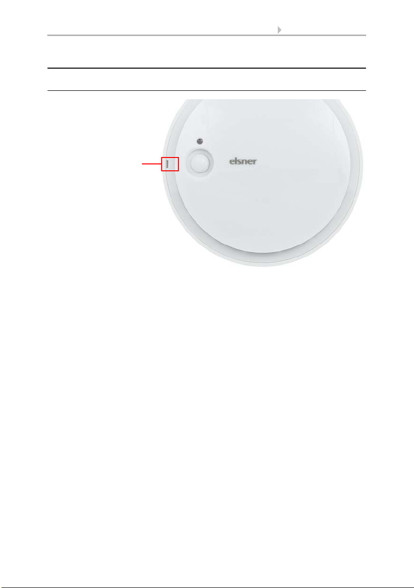
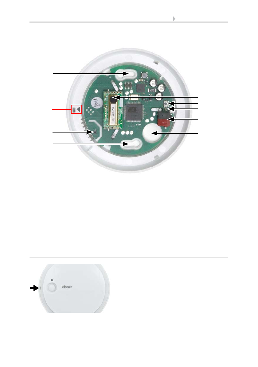
Fig. 1
A Recess to open the hous-
ing. When closing the
housing, the recess aligns
to the marking on the skirting
A
2.3. Construction of the sensor
2.3.1. Housing from the outside
Sensors Sewi KNX AQS and Sewi KNX AQS/TH-D • Version: 10.09.2018 • Technical changes and errors excepted.
Page 12
10 Installation and start-up
Fig. 2
1 a+b Long holes for mounting (hole distance 60 mm)
2 Sensors for temperature, humidity, pressure (only Sewi KNX AQS/TH-D)
3CO
2
-Sensor
4 Programming button
5 Programming LED
6KNX-terminal BUS +/7 Cable bushing
A Mark for aligning the cover
1a
A
1b
3
4
6
7
5
2
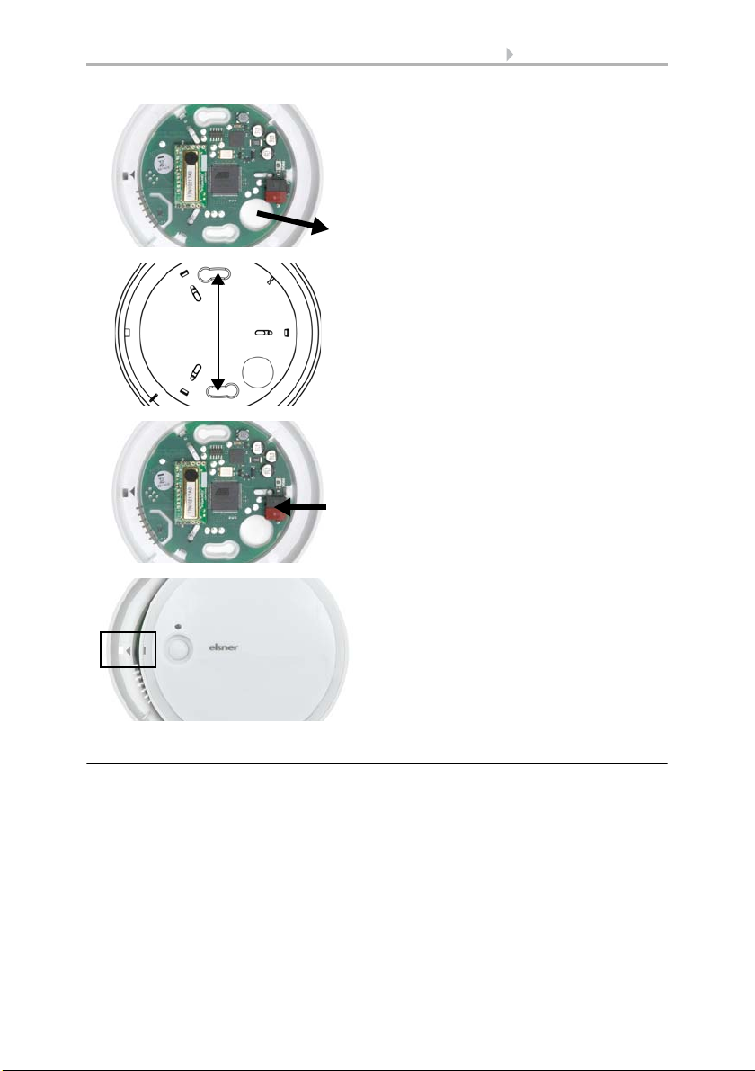
Fig. 3
Open the housing. To do this, carefully lift the
cover from the skirting. Start at the recess
(Fig. 2: A).
2.3.2. Printed circuit boards / connections
2.4. Assembly
Sensors Sewi KNX AQS and Sewi KNX AQS/TH-D • Version: 10.09.2018 • Technical changes and errors excepted.
Page 13
11 Installation and start-up
Fig. 4
Lead the bus cable through the cable
busching in the skirting.
Fig. 5
Screw the skirting to the wall or the ceiling.
Hole distance 60 mm.
60 mm
Fig. 6
Connect the KNX bus to the KNX terminal.
Fig. 7
Close the housing by positioning the cover
and snapping it into place. To do this, align
the recess on the cover to the marking on the
skirting (Fig. 1+2: A).
2.5. Notes on mounting and commissioning
Never expose the device to water (e.g. rain) or dust. This can damage the electronics.
You must not exceed a relative humidity of 85%. Avoid condensation.
The air slots on the side must not be closed or covered.
After the bus voltage has been applied, the device will enter an initialisation phase lasting a few seconds. During this phase no information can be received or sent via the
bus.
Sensors Sewi KNX AQS and Sewi KNX AQS/TH-D • Version: 10.09.2018 • Technical changes and errors excepted.
Page 14

12 Addressing the equipment
3. Addressing the equipment
The equipment is delivered with the bus address 15.15.254. You can program a different address in the ETS by overwriting the address 15.15.254 or by teaching the device
via the programming button.
The programming button is on the inside of the housing (Fig. 2: No. 3).
4. Maintenance
The air slots on the side must not get dirty or covered. As a rule, it is sufficient to wipe
the device with a soft, dry cloth twice a year.
Sensors Sewi KNX AQS and Sewi KNX AQS/TH-D • Version: 10.09.2018 • Technical changes and errors excepted.
Page 15

13 Transfer protocol
5. Transfer protocol
Units:
Temperatures in degrees Celsius
Air pressure in Pascal
Air humidity in %
Absolute air humidity in g/kg and/or g/m
CO2 content in ppm
Variables in %
5.1. List of all communication objects
Abbreviation flags:
C Communication
R Read
WWrite
T Transfer
UUpdate
No. Text Func-
1 Software version Output R-CT [217.1] DPT_Ver-
41 Temperature sensor: Malfunction Output R-CT [1.1] DPT_Switch 1 bit
42 Temperature sensor: External
measurement
43 Temperature sensor: Measured value Output R-CT [9.1] DPT_Val-
44 Temperature sensor: Total
measurement
45 Temperature sensor: Min./Max.
measurement query
46 Temperature sensor: Minimum
measurement
47 Temperature sensor: Maximum
measurement
48 Temperature sensor: Min./Max.
measurement reset
51 Temp. threshold value 1: Absolute
value
52 Temp. threshold value 1: (1:+ | 0:-) Input -WC- [1.1] DPT_Switch 1 bit
53 Temp. threshold value 1: Switching
delay from 0 to 1
54 Temp. threshold value 1: Switching
delay from 1 to 0
3
tion
Input -WCT [9.1] DPT_Val-
Output R-CT [9.1] DPT_Val-
Input -WC- [1.017] DPT_Trig-
Output R-CT [9.1] DPT_Val-
Output R-CT [9.1] DPT_Val-
Input -WC- [1.017] DPT_Trig-
Input/
Output
Input -WC- [7.5] DPT_Time-
Input -WC- [7.5] DPT_Time-
Flags DPT Typ Size
sion
ue_Temp
ue_Temp
ue_Temp
ger
ue_Temp
ue_Temp
ger
RWCT [9.1] DPT_Val-
ue_Temp
PeriodSec
PeriodSec
2 bytes
2 bytes
2 bytes
2 bytes
1 bit
2 bytes
2 bytes
1 bit
2 bytes
2 bytes
2 bytes
Sensors Sewi KNX AQS and Sewi KNX AQS/TH-D • Version: 10.09.2018 • Technical changes and errors excepted.
Page 16

14 Transfer protocol
No. Text Func-
Flags DPT Typ Size
tion
55 Temp. threshold value 1: Switching
Output R-CT [1.1] DPT_Switch 1 bit
output
56 Temp. threshold value 1: Switching
Input -WC- [1.1] DPT_Switch 1 bit
output block
58 Temp. threshold value 2: Absolute
value
Input/
Output
RWCT [9.1] DPT_Val-
ue_Temp
2 bytes
59 Temp. threshold value 2: (1:+ | 0:-) Input -WC- [1.1] DPT_Switch 1 bit
60 Temp. threshold value 2: Switching
delay from 0 to 1
61 Temp. threshold value 2: Switching
delay from 1 to 0
62 Temp. threshold value 2: Switching
Input -WC- [7.5] DPT_Time-
2 bytes
PeriodSec
Input -WC- [7.5] DPT_Time-
2 bytes
PeriodSec
Output R-CT [1.1] DPT_Switch 1 bit
output
63 Temp. threshold value 2: Switching
Input -WC- [1.1] DPT_Switch 1 bit
output block
65 Temp. threshold value 3: Absolute
value
Input/
Output
RWCT [9.1] DPT_Val-
ue_Temp
2 bytes
66 Temp. threshold value 3: (1:+ | 0:-) Input -WC- [1.1] DPT_Switch 1 bit
67 Temp. threshold value 3: Switching
delay from 0 to 1
68 Temp. threshold value 3: Switching
delay from 1 to 0
69 Temp. threshold value 3: Switching
Input -WC- [7.5] DPT_Time-
2 bytes
PeriodSec
Input -WC- [7.5] DPT_Time-
2 bytes
PeriodSec
Output R-CT [1.1] DPT_Switch 1 bit
output
70 Temp. threshold value 3: Switching
Input -WC- [1.1] DPT_Switch 1 bit
output block
72 Temp. threshold value 4: Absolute
value
Input/
Output
RWCT [9.1] DPT_Val-
ue_Temp
2 bytes
73 Temp. threshold value 4: (1:+ | 0:-) Input -WC- [1.1] DPT_Switch 1 bit
74 Temp. threshold value 4: Switching
delay from 0 to 1
75 Temp. threshold value 4: Switching
delay from 1 to 0
76 Temp. threshold value 4: Switching
Input -WC- [7.5] DPT_Time-
2 bytes
PeriodSec
Input -WC- [7.5] DPT_Time-
2 bytes
PeriodSec
Output R-CT [1.1] DPT_Switch 1 bit
output
77 Temp. threshold value 4: Switching
Input -WC- [1.1] DPT_Switch 1 bit
output block
311 Humidity sensor: Malfunction Output R-CT [1.1] DPT_Switch 1 bit
314 Humidity sensor: External
measurement
315 Humidity sensor: Measured value Output R-CT [9.7] DPT_Val-
Input -WCT [9.7] DPT_Val-
ue_Humidity
2 bytes
2 bytes
ue_Humidity
Sensors Sewi KNX AQS and Sewi KNX AQS/TH-D • Version: 10.09.2018 • Technical changes and errors excepted.
Page 17

15 Transfer protocol
No. Text Func-
Flags DPT Typ Size
tion
316 Humidity sensor: Total measurement Output R-CT [9.7] DPT_Val-
2 bytes
ue_Humidity
317 Humidity sensor: Min./Max.
measurement query
318 Humidity sensor: Minimum
measurement
319 Humidity sensor: Maximum
measurement
320 Humidity sensor: Min./Max.
measurement reset
331 Humidity threshold value 1: Absolute
value
Input -WC- [1.017] DPT_Trig-
ger
Output R-CT [9.7] DPT_Val-
ue_Humidity
Output R-CT [9.7] DPT_Val-
ue_Humidity
Input -WC- [1.017] DPT_Trig-
ger
Input/
Output
RWCT [9.7] DPT_Val-
ue_Humidity
1 bit
2 bytes
2 bytes
1 bit
2 bytes
332 Humidity threshold value 1: (1:+ | 0:-) Input -WC- [1.1] DPT_Switch 1 bit
333 Humidity threshold value 1: Delay
from 0 to 1
334 Humidity threshold value 1: Delay
from 1 to 0
335 Humidity threshold value 1:
Input -WC- [7.5] DPT_Time-
2 bytes
PeriodSec
Input -WC- [7.5] DPT_Time-
2 bytes
PeriodSec
Output R-CT [1.1] DPT_Switch 1 bit
Switching output
336 Humidity threshold value 1:
Input -WC- [1.1] DPT_Switch 1 bit
Switching output block
337 Humidity threshold value 2: Absolute
value
Input/
Output
RWCT [9.7] DPT_Val-
ue_Humidity
2 bytes
338 Humidity threshold value 2: (1:+ | 0:-) Input -WC- [1.1] DPT_Switch 1 bit
339 Humidity threshold value 2:
Delay from 0 to 1
340 Humidity threshold value 2:
Delay from 1 to 0
341 Humidity threshold value 2:
Input -WC- [7.5] DPT_Time-
2 bytes
PeriodSec
Input -WC- [7.5] DPT_Time-
2 bytes
PeriodSec
Output R-CT [1.1] DPT_Switch 1 bit
Switching output
342 Humidity threshold value 2:
Input -WC- [1.1] DPT_Switch 1 bit
Switching output block
343 Humidity threshold value 3: Absolute
value
Input/
Output
RWCT [9.7] DPT_Val-
ue_Humidity
2 bytes
344 Humidity threshold value 3: (1:+ | 0:-) Input -WC- [1.1] DPT_Switch 1 bit
345 Humidity threshold value 3:
Delay from 0 to 1
346 Humidity threshold value 3:
Delay from 1 to 0
347 Humidity threshold value 3:
Input -WC- [7.5] DPT_Time-
2 bytes
PeriodSec
Input -WC- [7.5] DPT_Time-
2 bytes
PeriodSec
Output R-CT [1.1] DPT_Switch 1 bit
Switching output
348 Humidity threshold value 3:
Input -WC- [1.1] DPT_Switch 1 bit
Switching output block
Sensors Sewi KNX AQS and Sewi KNX AQS/TH-D • Version: 10.09.2018 • Technical changes and errors excepted.
Page 18

16 Transfer protocol
No. Text Func-
Flags DPT Typ Size
tion
349 Humidity threshold value 4:
Absolute value
Input/
Output
RWCT [9.7] DPT_Val-
ue_Humidity
2 bytes
350 Humidity threshold value 4: (1:+ | 0:-) Input -WC- [1.1] DPT_Switch 1 bit
351 Humidity threshold value 4:
Delay from 0 to 1
352 Humidity threshold value 4:
Delay from 1 to 0
353 Humidity threshold value 4:
Input -WC- [7.5] DPT_Time-
2 bytes
PeriodSec
Input -WC- [7.5] DPT_Time-
2 bytes
PeriodSec
Output R-CT [1.1] DPT_Switch 1 bit
Switching output
354 Humidity threshold value 4:
Input -WC- [1.1] DPT_Switch 1 bit
Switching output block
381 Dewpoint: Measured value Output R-CT [9.1] DPT_Val-
2 bytes
ue_Temp
382 Coolant temp.: Threshold value Output R-CT [9.1] DPT_Val-
2 bytes
ue_Temp
383 Coolant temp.: Actual value Input RWCT [9.1] DPT_Val-
2 bytes
ue_Temp
384 Coolant temp.: Offset change
Input -WC- [1.1] DPT_Switch 1 bit
(1:+ | 0:-)
385 Coolant temp.: Current offset Output R-CT [9.1] DPT_Val-
2 bytes
ue_Temp
386 Coolant temp.: Switching delay from
0 to 1
387 Coolant temp.: Switching delay from
1 to 0
Input -WC- [7.5] DPT_Time-
PeriodSec
Input -WC- [7.5] DPT_Time-
PeriodSec
2 bytes
2 bytes
388 Coolant temp.: Switching output Output R-CT [1.1] DPT_Switch 1 bit
389 Coolant temp.: Switching output
Input -WC- [1.1] DPT_Switch 1 bit
block
391 Absolute humidity [g/kg] Output R-CT [14.5] DPT_Val-
4 bytes
ue_Amplitude
392 Absolute humidity [g/m²] Output R-CT [14.17] DPT_Val-
4 bytes
ue_Density
394 Ambient climate status:
Output R-CT [1.1] DPT_Switch 1 bit
1 = comfortable | 0 = uncomfortable
395 Ambient climate status: Text Output R-CT [16.0]
DPT_String_ASCII
14
bytes
401 Air pressure sensor: Malfunction Output R-CT [1.1] DPT_Switch 1 bit
402 Air pressure sensor: Normal
measurement [Pa]
403 Air pressure sensor: Barometric
measurement [Pa]
404 Air pressure sensor: Min./Max.
measurement query
Output R-CT [14.58] DPT_Val-
ue_Pressure
Output R-CT [14.58] DPT_Val-
ue_Pressure
Input -WC- [1.017] DPT_Trig-
ger
4 bytes
4 bytes
1 bit
Sensors Sewi KNX AQS and Sewi KNX AQS/TH-D • Version: 10.09.2018 • Technical changes and errors excepted.
Page 19

17 Transfer protocol
No. Text Func-
tion
405 Air pressure sensor: Min. normal
Output R-CT [14.58] DPT_Val-
measurement [Pa]
406 Air pressure sensor: Min. barometric
Output R-CT [14.58] DPT_Val-
measurement [Pa]
407 Air pressure sensor: Max. normal
Output R-CT [14.58] DPT_Val-
measurement [Pa]
408 Air pressure sensor: Max. barometric
Output R-CT [14.58] DPT_Val-
measurement [Pa]
409 Air pressure sensor: Min./Max.
Input -WC- [1.017] DPT_Trig-
measurement reset
410 Air pressure sensor: Pressure range
Output R-CT [16.0]
text
411 Air pressure threshold value 1:
Absolute value
412 Air pressure threshold value 1:
Input/
Output
Input -WC- [1.1] DPT_Switch 1 bit
(1:+ | 0:-)
413 Air pressure threshold value 1:
Input -WC- [7.5] DPT_Time-
Delay from 0 to 1
414 Air pressure threshold value 1:
Input -WC- [7.5] DPT_Time-
Delay from 1 to 0
415 Air pressure threshold value 1:
Output R-CT [1.1] DPT_Switch 1 bit
Switching output
416 Air pressure threshold value 1:
Input -WC- [1.1] DPT_Switch 1 bit
Switching output block
417 Air pressure threshold value 2:
Absolute value
418 Air pressure threshold value 2:
Input/
Output
Input -WC- [1.1] DPT_Switch 1 bit
(1:+ | 0:-)
419 Air pressure threshold value 2:
Input -WC- [7.5] DPT_Time-
Delay from 0 to 1
420 Air pressure threshold value 2:
Input -WC- [7.5] DPT_Time-
Delay from 1 to 0
421 Air pressure threshold value 2:
Output R-CT [1.1] DPT_Switch 1 bit
Switching output
422 Air pressure threshold value 2:
Input -WC- [1.1] DPT_Switch 1 bit
Switching output block
423 Air pressure threshold value 3:
Absolute value
424 Air pressure threshold value 3:
Input/
Output
Input -WC- [1.1] DPT_Switch 1 bit
(1:+ | 0:-)
425 Air pressure threshold value 3:
Input -WC- [7.5] DPT_Time-
Delay from 0 to 1
Flags DPT Typ Size
4 bytes
ue_Pressure
4 bytes
ue_Pressure
4 bytes
ue_Pressure
4 bytes
ue_Pressure
1 bit
ger
14
DPT_String_ASCII
RWCT [14.58] DPT_Val-
bytes
4 bytes
ue_Pressure
2 bytes
PeriodSec
2 bytes
PeriodSec
RWCT [14.58] DPT_Val-
4 bytes
ue_Pressure
2 bytes
PeriodSec
2 bytes
PeriodSec
RWCT [14.58] DPT_Val-
4 bytes
ue_Pressure
2 bytes
PeriodSec
Sensors Sewi KNX AQS and Sewi KNX AQS/TH-D • Version: 10.09.2018 • Technical changes and errors excepted.
Page 20

18 Transfer protocol
No. Text Func-
Flags DPT Typ Size
tion
426 Air pressure threshold value 3:
Delay from 1 to 0
427 Air pressure threshold value 3:
Input -WC- [7.5] DPT_Time-
2 bytes
PeriodSec
Output R-CT [1.1] DPT_Switch 1 bit
Switching output
428 Air pressure threshold value 3:
Input -WC- [1.1] DPT_Switch 1 bit
Switching output block
429 Air pressure threshold value 4:
Absolute value
430 Air pressure threshold value 4:
Input/
Output
RWCT [14.58] DPT_Val-
ue_Pressure
4 bytes
Input -WC- [1.1] DPT_Switch 1 bit
(1:+ | 0:-)
431 Air pressure threshold value 4:
Delay from 0 to 1
432 Air pressure threshold value 4:
Delay from 1 to 0
433 Air pressure threshold value 4:
Input -WC- [7.5] DPT_Time-
2 bytes
PeriodSec
Input -WC- [7.5] DPT_Time-
2 bytes
PeriodSec
Output R-CT [1.1] DPT_Switch 1 bit
Switching output
434 Air pressure threshold value 4:
Input -WC- [1.1] DPT_Switch 1 bit
Switching output block
441 CO2 Sensor: Malfunction Output R-CT [1.1] DPT_Switch 1 bit
442 CO2 Sensor: External measurement Input -WCT [9,008] DPT_Val-
2 bytes
ue_AirQuality
443 CO2 Sensor: Measured value Output R-CT [9,008] DPT_Val-
2 bytes
ue_AirQuality
444 CO2 Sensor: Total measurement Output R-CT [9,008] DPT_Val-
2 bytes
ue_AirQuality
445 CO2 Sensor: Max. measurement
query
446 CO2 Sensor: Maximum
measurement
447 CO2 Sensor: Max. reset
measurement
448 CO2 threshold value 1: Absolute
value
Input -WC- [1.017] DPT_Trig-
ger
Output R-CT [9,008] DPT_Val-
ue_AirQuality
Input -WC- [1.017] DPT_Trig-
ger
Input/
Output
RWCT [9,008] DPT_Val-
ue_AirQuality
1 bit
2 bytes
1 bit
2 bytes
449 CO2 threshold value 1: (1:+ | 0:-) Input -WC- [1.1] DPT_Switch 1 bit
450 CO2 threshold value 1:
Delay from 0 to 1
451 CO2 threshold value 1:
Delay from 1 to 0
452 CO2 threshold value 1:
Input -WC- [7.5] DPT_Time-
2 bytes
PeriodSec
Input -WC- [7.5] DPT_Time-
2 bytes
PeriodSec
Output R-CT [1.1] DPT_Switch 1 bit
Switching output
453 CO2 threshold value 1:
Input -WC- [1.1] DPT_Switch 1 bit
Switching output block
Sensors Sewi KNX AQS and Sewi KNX AQS/TH-D • Version: 10.09.2018 • Technical changes and errors excepted.
Page 21

19 Transfer protocol
No. Text Func-
Flags DPT Typ Size
tion
454 CO2 threshold value 2:
Absolute value
Input/
Output
RWCT [9,008] DPT_Val-
ue_AirQuality
2 bytes
455 CO2 threshold value 2: (1:+ | 0:-) Input -WC- [1.1] DPT_Switch 1 bit
456 CO2 threshold value 2:
Delay from 0 to 1
457 CO2 threshold value 2:
Delay from 1 to 0
458 CO2 threshold value 2:
Input -WC- [7.5] DPT_Time-
2 bytes
PeriodSec
Input -WC- [7.5] DPT_Time-
2 bytes
PeriodSec
Output R-CT [1.1] DPT_Switch 1 bit
Switching output
459 CO2 threshold value 2:
Input -WC- [1.1] DPT_Switch 1 bit
Switching output block
460 CO2 threshold value 3:
Absolute value
Input/
Output
RWCT [9,008] DPT_Val-
ue_AirQuality
2 bytes
461 CO2 threshold value 3: (1:+ | 0:-) Input -WC- [1.1] DPT_Switch 1 bit
462 CO2 threshold value 3:
Delay from 0 to 1
463 CO2 threshold value 3:
Delay from 1 to 0
464 CO2 threshold value 3:
Input -WC- [7.5] DPT_Time-
2 bytes
PeriodSec
Input -WC- [7.5] DPT_Time-
2 bytes
PeriodSec
Output R-CT [1.1] DPT_Switch 1 bit
Switching output
465 CO2 threshold value 3:
Input -WC- [1.1] DPT_Switch 1 bit
Switching output block
466 CO2 threshold value 4:
Absolute value
Input/
Output
RWCT [9,008] DPT_Val-
ue_AirQuality
2 bytes
467 CO2 threshold value 4: (1:+ | 0:-) Input -WC- [1.1] DPT_Switch 1 bit
468 CO2 threshold value 4:
Delay from 0 to 1
469 CO2 threshold value 4:
Delay from 1 to 0
470 CO2 threshold value 4:
Input -WC- [7.5] DPT_Time-
2 bytes
PeriodSec
Input -WC- [7.5] DPT_Time-
2 bytes
PeriodSec
Output R-CT [1.1] DPT_Switch 1 bit
Switching output
471 CO2 threshold value 4:
Input -WC- [1.1] DPT_Switch 1 bit
Switching output block
472 CO2 controller: Block (1: block) Input -WC- [1.2] DPT_Bool 1 bit
473 CO2 controller: Setpoint value Input/
Output
474 CO2 controller: Setpoint value
Input -WC- [1.2] DPT_Bool 1 bit
RWCT [9,008] DPT_Val-
ue_AirQuality
2 bytes
(1:+ | 0:-)
475 CO2 controller: Control variable
Output R-CT [5.1] DPT_Scaling 1 byte
ventilation
476 CO2 controller: Control variable
Output R-CT [5.1] DPT_Scaling 1 byte
ventilation level 2
Sensors Sewi KNX AQS and Sewi KNX AQS/TH-D • Version: 10.09.2018 • Technical changes and errors excepted.
Page 22

20 Transfer protocol
No. Text Func-
Flags DPT Typ Size
tion
477 CO2 controller: Ventilation status
Output R-CT [1.1] DPT_Switch 1 bit
(1:ON | 0:OFF)
478 CO2 controller: Status ventilation
Output R-CT [1.1] DPT_Switch 1 bit
level 2 (1:ON | 0:OFF)
481 Temp. controller: HVAC mode
(priority 1)
482 Temp. controller: HVAC mode
(priority 2)
483 Temp. controller: Mode frost/heat
Input -WC- [20.102] DPT_H-
1 byte
VACMode
Input RWCT [20.102] DPT_H-
1 byte
VACMode
Input RWCT [1.1] DPT_Switch 1 bit
protection activation
484 Temp. controller: Block (1 = Blocking) Input -WC- [1.1] DPT_Switch 1 bit
485 Temp. controller: Current setpoint Output R-CT [9.1] DPT_Val-
2 bytes
ue_Temp
486 Temp. controller: Switching
Input -WC- [1.1] DPT_Switch 1 bit
(0: Heating | 1: Cooling)
487 Temp. controller: Setpoint comfort
heating
488 Temp. controller: Setpoint comfort
Input/
Output
RWCT [9.1] DPT_Val-
ue_Temp
2 bytes
Input -WC- [1.1] DPT_Switch 1 bit
heating (1:+ | 0: -)
489 Temp. controller: Setpoint comfort
cooling
490 Temp. controller: Setpoint comfort
Input/
Output
RWCT [9.1] DPT_Val-
ue_Temp
2 bytes
Input -WC- [1.1] DPT_Switch 1 bit
cooling (1:+ | 0: -)
491 Temp. controller: Basic 16-bit
setpoint shift
492 Temp. controller: Setpoint standby
heating
493 Temp. controller: Setpoint standby
Input/
Output
Input/
Output
RWCT [9.1] DPT_Val-
ue_Temp
RWCT [9.1] DPT_Val-
ue_Temp
2 bytes
2 bytes
Input -WC- [1.1] DPT_Switch 1 bit
heating (1:+ | 0: -)
494 Temp. controller: Setpoint standby
cooling
495 Temp. controller: Setpoint standby
Input/
Output
RWCT [9.1] DPT_Val-
ue_Temp
2 bytes
Input -WC- [1.1] DPT_Switch 1 bit
cooling (1:+ | 0: -)
496 Temp. controller: Setpoint eco
heating
497 Temp. controller: Setpoint, eco
Input/
Output
RWCT [9.1] DPT_Val-
ue_Temp
2 bytes
Input -WC- [1.1] DPT_Switch 1 bit
heating (1:+ | 0: -)
498 Temp. controller: Setpoint eco
cooling
499 Temp. controller: Setpoint, eco
Input/
Output
RWCT [9.1] DPT_Val-
ue_Temp
2 bytes
Input -WC- [1.1] DPT_Switch 1 bit
cooling (1:+ | 0: -)
500 Temp. controller: Control variable,
Output R-CT [5.1] DPT_Scaling 1 byte
heating (level 1)
Sensors Sewi KNX AQS and Sewi KNX AQS/TH-D • Version: 10.09.2018 • Technical changes and errors excepted.
Page 23

21 Transfer protocol
No. Text Func-
Flags DPT Typ Size
tion
501 Temp. controller: Control variable,
Output R-CT [5.1] DPT_Scaling 1 byte
heating (level 2)
502 Temp. controller: Control variable,
Output R-CT [5.1] DPT_Scaling 1 byte
cooling (level 1)
503 Temp. controller: Control variable,
Output R-CT [5.1] DPT_Scaling 1 byte
cooling (level 2)
504 Temperature controller: Variable for
Output R-CT [5.1] DPT_Scaling 1 byte
4/6-way valve
505 Temp. controller: Status heating
Output R-CT [1.1] DPT_Switch 1 bit
level 1 (1:ON | 0:OFF)
506 Temp. controller: Status heating
Output R-CT [1.1] DPT_Switch 1 bit
level 2 (1:ON | 0:OFF)
507 Temp. controller: Status cooling
Output R-CT [1.1] DPT_Switch 1 bit
level 1 (1:ON | 0:OFF)
508 Temp. controller: Status cooling
Output R-CT [1.1] DPT_Switch 1 bit
level 2 (1:ON | 0:OFF)
509 Temp. controller: Comfort extension
status
510 Temp. controller: Comfort extension
time
515 European Summer Time: Outside
temperature
516 European Summer Time: Setpoint
value
517 European Summer Time: Block
Input/
RWCT [1.1] DPT_Switch 1 bit
Output
Input RWCT [7.5] DPT_Time-
2 bytes
PeriodSec
Input -WCT [9.1] DPT_Val-
2 bytes
ue_Temp
Output R-CT [9.1] DPT_Val-
2 bytes
ue_Temp
Input -WC- [1.1] DPT_Switch 1 bit
(1 = Blocking)
521 Humidity controller: Block (1: block) Input -WC- [1.2] DPT_Bool 1 bit
522 Humidity controller: Setpoint value Input/
Output
523 Humidity controller: Setpoint
Input -WC- [1.2] DPT_Bool 1 bit
RWCT [9,007] DPT_Val-
ue_Humidity
2 bytes
value (1:+ | 0:-)
524 Humidity controller: Control variable
Output R-CT [5.1] DPT_Scaling 1 byte
dehumidification
525 Humidity controller: Control variable
Output R-CT [5.1] DPT_Scaling 1 byte
dehumidification level 2
526 Humidity controller: Control variable
Output R-CT [5.1] DPT_Scaling 1 byte
humidification
527 Humidity controller:
Output R-CT [1.1] DPT_Switch 1 bit
Dehumidification status
(1:ON | 0:OFF)
528 Humidity controller:
Output R-CT [1.1] DPT_Switch 1 bit
Dehumidification 2 status
(1:ON | 0:OFF)
Sensors Sewi KNX AQS and Sewi KNX AQS/TH-D • Version: 10.09.2018 • Technical changes and errors excepted.
Page 24

22 Transfer protocol
No. Text Func-
tion
529 Humidity controller: Humidification
Output R-CT [1.1] DPT_Switch 1 bit
status (1:ON | 0:OFF)
1111 Control variable comparator 1:
Input -WC- [5.1] DPT_Scaling 1 byte
Input 1
1112 Control variable comparator 1:
Input -WC- [5.1] DPT_Scaling 1 byte
Input 2
1113 Control variable comparator 1:
Input -WC- [5.1] DPT_Scaling 1 byte
Input 3
1114 Control variable comparator 1:
Input -WC- [5.1] DPT_Scaling 1 byte
Input 4
1115 Control variable comparator 1:
Input -WC- [5.1] DPT_Scaling 1 byte
Input 5
1116 Control variable comparator 1:
Output R-CT [5.1] DPT_Scaling 1 byte
Output
1117 Control variable comparator 1:
Output -WC- [1.2] DPT_Bool 1 bit
Block: block)
1118 Control variable comparator 2:
Input -WC- [5.1] DPT_Scaling 1 byte
Input 1
1119 Control variable comparator 2:
Input -WC- [5.1] DPT_Scaling 1 byte
Input 2
1120 Control variable comparator 2:
Input -WC- [5.1] DPT_Scaling 1 byte
Input 3
1121 Control variable comparator 2:
Input -WC- [5.1] DPT_Scaling 1 byte
Input 4
1122 Control variable comparator 2:
Input -WC- [5.1] DPT_Scaling 1 byte
Input 5
1123 Control variable comparator 2:
Output R-CT [5.1] DPT_Scaling 1 byte
Output
1124 Control variable comparator 2:
Output -WC- [1.2] DPT_Bool 1 bit
Block (1: block)
1125 Control variable comparator 3:
Input -WC- [5.1] DPT_Scaling 1 byte
Input 1
1126 Control variable comparator 3:
Input -WC- [5.1] DPT_Scaling 1 byte
Input 2
1127 Control variable comparator 3:
Input -WC- [5.1] DPT_Scaling 1 byte
Input 3
1128 Control variable comparator 3:
Input -WC- [5.1] DPT_Scaling 1 byte
Input 4
1129 Control variable comparator 3:
Input -WC- [5.1] DPT_Scaling 1 byte
Input 5
1130 Control variable comparator 3:
Output R-CT [5.1] DPT_Scaling 1 byte
Output
Flags DPT Typ Size
Sensors Sewi KNX AQS and Sewi KNX AQS/TH-D • Version: 10.09.2018 • Technical changes and errors excepted.
Page 25

23 Transfer protocol
No. Text Func-
Flags DPT Typ Size
tion
1131 Control variable comparator 3:
Output -WC- [1.2] DPT_Bool 1 bit
Block (1: block)
1132 Control variable comparator 4:
Input -WC- [5.1] DPT_Scaling 1 byte
Input 1
1133 Control variable comparator 4:
Input -WC- [5.1] DPT_Scaling 1 byte
Input 2
1134 Control variable comparator 4:
Input -WC- [5.1] DPT_Scaling 1 byte
Input 3
1135 Control variable comparator 4:
Input -WC- [5.1] DPT_Scaling 1 byte
Input 4
1136 Control variable comparator 4:
Input -WC- [5.1] DPT_Scaling 1 byte
Input 5
1137 Control variable comparator 4:
Output R-CT [5.1] DPT_Scaling 1 byte
Output
1138 Control variable comparator 4:
Output -WC- [1.2] DPT_Bool 1 bit
Block (1: block)
1141 Computer 1: Input I1 Input RWCT Depending on
4 bytes
setting
1142 Computer 1: Input I2 Input RWCT Depending on
4 bytes
setting
1143 Computer 1: Input I3 Input RWCT Depending on
4 bytes
setting
1144 Computer 1: Output O1 Output R-CT Depending on
4 bytes
setting
1145 Computer 1: Output O2 Output R-CT Depending on
4 bytes
setting
1146 Computer 1: Condition text Output R-CT [16.0]
DPT_String_ASCII
14
bytes
1147 Computer 1: Monitoring status Output R-CT [1.1] DPT_Switch 1 bit
1148 Computer 1: Block (1: block) Input -WC- [1.1] DPT_Switch 1 bit
1149 Computer 2: Input I1 Input RWCT Depending on
4 bytes
setting
1150 Computer 2: Input I2 Input RWCT Depending on
4 bytes
setting
1151 Computer 2: Input I3 Input RWCT Depending on
4 bytes
setting
1152 Computer 2: Output O1 Output R-CT Depending on
4 bytes
setting
1153 Computer 2: Output O2 Output R-CT Depending on
4 bytes
setting
1154 Computer 2: Condition text Output R-CT [16.0]
DPT_String_ASCII
14
bytes
1155 Computer 2: Monitoring status Output R-CT [1.1] DPT_Switch 1 bit
Sensors Sewi KNX AQS and Sewi KNX AQS/TH-D • Version: 10.09.2018 • Technical changes and errors excepted.
Page 26

24 Transfer protocol
No. Text Func-
Flags DPT Typ Size
tion
1156 Computer 2: Block (1: block) Input -WC- [1.1] DPT_Switch 1 bit
1157 Computer 3: Input I1 Input RWCT Depending on
4 bytes
setting
1158 Computer 3: Input I2 Input RWCT Depending on
4 bytes
setting
1159 Computer 3: Input I3 Input RWCT Depending on
4 bytes
setting
1160 Computer 3: Output O1 Output R-CT Depending on
4 bytes
setting
1161 Computer 3: Output O2 Output R-CT Depending on
4 bytes
setting
1162 Computer 3: Condition text Output R-CT [16.0]
DPT_String_ASCII
14
bytes
1163 Computer 3: Monitoring status Output R-CT [1.1] DPT_Switch 1 bit
1164 Computer 3: Block (1: block) Input -WC- [1.1] DPT_Switch 1 bit
1165 Computer 4: Input I1 Input RWCT Depending on
4 bytes
setting
1166 Computer 4: Input I2 Input RWCT Depending on
4 bytes
setting
1167 Computer 4: Input I3 Input RWCT Depending on
4 bytes
setting
1168 Computer 4: Output O1 Output R-CT Depending on
4 bytes
setting
1169 Computer 4: Output O2 Output R-CT Depending on
4 bytes
setting
1170 Computer 4: Condition text Output R-CT [16.0]
DPT_String_ASCII
14
bytes
1171 Computer 4: Monitoring status Output R-CT [1.1] DPT_Switch 1 bit
1172 Computer 4: Block (1: block) Input -WC- [1.1] DPT_Switch 1 bit
1173 Computer 5: Input I1 Input RWCT Depending on
4 bytes
setting
1174 Computer 5: Input I2 Input RWCT Depending on
4 bytes
setting
1175 Computer 5: Input I3 Input RWCT Depending on
4 bytes
setting
1176 Computer 5: Output O1 Output R-CT Depending on
4 bytes
setting
1177 Computer 5: Output O2 Output R-CT Depending on
4 bytes
setting
1178 Computer 5: Condition text Output R-CT [16.0]
DPT_String_ASCII
14
bytes
1179 Computer 5: Monitoring status Output R-CT [1.1] DPT_Switch 1 bit
1180 Computer 5: Block (1: block) Input -WC- [1.1] DPT_Switch 1 bit
Sensors Sewi KNX AQS and Sewi KNX AQS/TH-D • Version: 10.09.2018 • Technical changes and errors excepted.
Page 27

25 Transfer protocol
No. Text Func-
Flags DPT Typ Size
tion
1181 Computer 6: Input I1 Input RWCT Depending on
4 bytes
setting
1182 Computer 6: Input I2 Input RWCT Depending on
4 bytes
setting
1183 Computer 6: Input I3 Input RWCT Depending on
4 bytes
setting
1184 Computer 6: Output O1 Output R-CT Depending on
4 bytes
setting
1185 Computer 6: Output O2 Output R-CT Depending on
4 bytes
setting
1186 Computer 6: Condition text Output R-CT [16.0]
DPT_String_ASCII
14
bytes
1187 Computer 6: Monitoring status Output R-CT [1.1] DPT_Switch 1 bit
1188 Computer 6: Block (1: block) Input -WC- [1.1] DPT_Switch 1 bit
1189 Computer 7: Input I1 Input RWCT Depending on
4 bytes
setting
1190 Computer 7: Input I2 Input RWCT Depending on
4 bytes
setting
1191 Computer 7: Input I3 Input RWCT Depending on
4 bytes
setting
1192 Computer 7: Output O1 Output R-CT Depending on
4 bytes
setting
1193 Computer 7: Output O2 Output R-CT Depending on
4 bytes
setting
1194 Computer 7: Condition text Output R-CT [16.0]
DPT_String_ASCII
14
bytes
1195 Computer 7: Monitoring status Output R-CT [1.1] DPT_Switch 1 bit
1196 Computer 7: Block (1: block) Input -WC- [1.1] DPT_Switch 1 bit
1197 Computer 8: Input I1 Input RWCT Depending on
4 bytes
setting
1198 Computer 8: Input I2 Input RWCT Depending on
4 bytes
setting
1199 Computer 8: Input I3 Input RWCT Depending on
4 bytes
setting
1200 Computer 8: Output O1 Output R-CT Depending on
4 bytes
setting
1201 Computer 8: Output O2 Output R-CT Depending on
4 bytes
setting
1202 Computer 8: Condition text Output R-CT [16.0]
DPT_String_ASCII
14
bytes
1203 Computer 8: Monitoring status Output R-CT [1.1] DPT_Switch 1 bit
1204 Computer 8: Block (1: block) Input -WC- [1.1] DPT_Switch 1 bit
1391 Logic input 1 Input -WC- [1.2] DPT_Bool 1 bit
Sensors Sewi KNX AQS and Sewi KNX AQS/TH-D • Version: 10.09.2018 • Technical changes and errors excepted.
Page 28

26 Transfer protocol
No. Text Func-
Flags DPT Typ Size
tion
1392 Logic input 2 Input -WC- [1.2] DPT_Bool 1 bit
1393 Logic input 3 Input -WC- [1.2] DPT_Bool 1 bit
1394 Logic input 4 Input -WC- [1.2] DPT_Bool 1 bit
1395 Logic input 5 Input -WC- [1.2] DPT_Bool 1 bit
1396 Logic input 6 Input -WC- [1.2] DPT_Bool 1 bit
1397 Logic input 7 Input -WC- [1.2] DPT_Bool 1 bit
1398 Logic input 8 Input -WC- [1.2] DPT_Bool 1 bit
1399 Logic input 9 Input -WC- [1.2] DPT_Bool 1 bit
1400 Logic input 10 Input -WC- [1.2] DPT_Bool 1 bit
1401 Logic input 11 Input -WC- [1.2] DPT_Bool 1 bit
1402 Logic input 12 Input -WC- [1.2] DPT_Bool 1 bit
1403 Logic input 13 Input -WC- [1.2] DPT_Bool 1 bit
1404 Logic input 14 Input -WC- [1.2] DPT_Bool 1 bit
1405 Logic input 15 Input -WC- [1.2] DPT_Bool 1 bit
1406 Logic input 16 Input -WC- [1.2] DPT_Bool 1 bit
1411 AND logic 1: 1-bit switching output Output R-CT [1.2] DPT_Bool 1 bit
1412 AND logic 1: 8-bit output A Output R-CT [5.010] DPT_-
1 byte
Value_1_Ucount
1413 AND logic 1: 8-bit output B Output R-CT [5.010] DPT_-
1 byte
Value_1_Ucount
1414 AND logic 1: Block Input -WC- [1.1] DPT_Switch 1 bit
1415 AND logic 2: 1-bit switching output Output R-CT [1.2] DPT_Bool 1 bit
1416 AND logic 2: 8-bit output A Output R-CT [5.010] DPT_-
1 byte
Value_1_Ucount
1417 AND logic 2: 8-bit output B Output R-CT [5.010] DPT_-
1 byte
Value_1_Ucount
1418 AND logic 2: Block Input -WC- [1.1] DPT_Switch 1 bit
1419 AND logic 3: 1-bit switching output Output R-CT [1.2] DPT_Bool 1 bit
1420 AND logic 3: 8-bit output A Output R-CT [5.010] DPT_-
1 byte
Value_1_Ucount
1421 AND logic 3: 8-bit output B Output R-CT [5.010] DPT_-
1 byte
Value_1_Ucount
1422 AND logic 3: Block Input -WC- [1.1] DPT_Switch 1 bit
1423 AND logic 4: 1-bit switching output Output R-CT [1.2] DPT_Bool 1 bit
1424 AND logic 4: 8-bit output A Output R-CT [5.010] DPT_-
1 byte
Value_1_Ucount
1425 AND logic 4: 8-bit output B Output R-CT [5.010] DPT_-
1 byte
Value_1_Ucount
1426 AND logic 4: Block Input -WC- [1.1] DPT_Switch 1 bit
1427 AND logic 5: 1-bit switching output Output R-CT [1.2] DPT_Bool 1 bit
Sensors Sewi KNX AQS and Sewi KNX AQS/TH-D • Version: 10.09.2018 • Technical changes and errors excepted.
Page 29

27 Transfer protocol
No. Text Func-
Flags DPT Typ Size
tion
1428 AND logic 5: 8-bit output A Output R-CT [5.010] DPT_-
1 byte
Value_1_Ucount
1429 AND logic 5: 8-bit output B Output R-CT [5.010] DPT_-
1 byte
Value_1_Ucount
1430 AND logic 5: Block Input -WC- [1.1] DPT_Switch 1 bit
1431 AND logic 6: 1-bit switching output Output R-CT [1.2] DPT_Bool 1 bit
1432 AND logic 6: 8-bit output A Output R-CT [5.010] DPT_-
1 byte
Value_1_Ucount
1433 AND logic 6: 8-bit output B Output R-CT [5.010] DPT_-
1 byte
Value_1_Ucount
1434 AND logic 6: Block Input -WC- [1.1] DPT_Switch 1 bit
1435 AND logic 7: 1-bit switching output Output R-CT [1.2] DPT_Bool 1 bit
1436 AND logic 7: 8-bit output A Output R-CT [5.010] DPT_-
1 byte
Value_1_Ucount
1437 AND logic 7: 8-bit output B Output R-CT [5.010] DPT_-
1 byte
Value_1_Ucount
1438 AND logic 7: Block Input -WC- [1.1] DPT_Switch 1 bit
1439 AND logic 8: 1-bit switching output Output R-CT [1.2] DPT_Bool 1 bit
1440 AND logic 8: 8-bit output A Output R-CT [5.010] DPT_-
1 byte
Value_1_Ucount
1441 AND logic 8: 8-bit output B Output R-CT [5.010] DPT_-
1 byte
Value_1_Ucount
1442 AND logic 8: Block Input -WC- [1.1] DPT_Switch 1 bit
1443 OR logic 1: 1-bit switching output Output R-CT [1.2] DPT_Bool 1 bit
1444 OR logic 1: 8-bit output A Output R-CT [5.010] DPT_-
1 byte
Value_1_Ucount
1445 OR logic 1: 8-bit output B Output R-CT [5.010] DPT_-
1 byte
Value_1_Ucount
1446 OR logic 1: Block Input -WC- [1.1] DPT_Switch 1 bit
1447 OR logic 2: 1-bit switching output Output R-CT [1.2] DPT_Bool 1 bit
1448 OR logic 2: 8-bit output A Output R-CT [5.010] DPT_-
1 byte
Value_1_Ucount
1449 OR logic 2: 8-bit output B Output R-CT [5.010] DPT_-
1 byte
Value_1_Ucount
1450 OR logic 2: Block Input -WC- [1.1] DPT_Switch 1 bit
1451 OR logic 3: 1-bit switching output Output R-CT [1.2] DPT_Bool 1 bit
1452 OR logic 3: 8-bit output A Output R-CT [5.010] DPT_-
1 byte
Value_1_Ucount
1453 OR logic 3: 8-bit output B Output R-CT [5.010] DPT_-
1 byte
Value_1_Ucount
1454 OR logic 3: Block Input -WC- [1.1] DPT_Switch 1 bit
1455 OR logic 4: 1-bit switching output Output R-CT [1.2] DPT_Bool 1 bit
Sensors Sewi KNX AQS and Sewi KNX AQS/TH-D • Version: 10.09.2018 • Technical changes and errors excepted.
Page 30

28 Parameter setting
No. Text Func-
tion
1456 OR logic 4: 8-bit output A Output R-CT [5.010] DPT_-
1457 OR logic 4: 8-bit output B Output R-CT [5.010] DPT_-
1458 OR logic 4: Block Input -WC- [1.1] DPT_Switch 1 bit
1459 OR logic 5: 1-bit switching output Output R-CT [1.2] DPT_Bool 1 bit
1460 OR logic 5: 8-bit output A Output R-CT [5.010] DPT_-
1461 OR logic 5: 8-bit output B Output R-CT [5.010] DPT_-
1462 OR logic 5: Block Input -WC- [1.1] DPT_Switch 1 bit
1463 OR logic 6: 1-bit switching output Output R-CT [1.2] DPT_Bool 1 bit
1464 OR logic 6: 8-bit output A Output R-CT [5.010] DPT_-
1465 OR logic 6: 8-bit output B Output R-CT [5.010] DPT_-
1466 OR logic 6: Block Input -WC- [1.1] DPT_Switch 1 bit
1467 OR logic 7: 1-bit switching output Output R-CT [1.2] DPT_Bool 1 bit
1468 OR logic 7: 8-bit output A Output R-CT [5.010] DPT_-
1469 OR logic 7: 8-bit output B Output R-CT [5.010] DPT_-
1470 OR logic 7: Block Input -WC- [1.1] DPT_Switch 1 bit
1471 OR logic 8: 1-bit switching output Output R-CT [1.2] DPT_Bool 1 bit
1472 OR logic 8: 8-bit output A Output R-CT [5.010] DPT_-
1473 OR logic 8: 8-bit output B Output R-CT [5.010] DPT_-
1474 OR logic 8: Block Input -WC- [1.1] DPT_Switch 1 bit
Flags DPT Typ Size
1 byte
Value_1_Ucount
1 byte
Value_1_Ucount
1 byte
Value_1_Ucount
1 byte
Value_1_Ucount
1 byte
Value_1_Ucount
1 byte
Value_1_Ucount
1 byte
Value_1_Ucount
1 byte
Value_1_Ucount
1 byte
Value_1_Ucount
1 byte
Value_1_Ucount
6. Parameter setting
6.1. Behaviour on power failure/ restoration of power
Behaviour following a failure of the bus power supply:
The device sends nothing.
Behaviour on bus restoration of power and following programming or reset:
The device sends all outputs according to their send behaviour set in the parameters
with the delays established in the "General settings" parameter block.
Sensors Sewi KNX AQS and Sewi KNX AQS/TH-D • Version: 10.09.2018 • Technical changes and errors excepted.
Page 31

29 Parameter setting
6.2. General settings
Set basic characteristics for the data transfer.
Send delay after power-up and programming for:
Measured values 5 s • ... • 2 h
Threshold values and switching outputs 5 s • ... • 2 h
Controller objects 5 s • ... • 2 h
Comparator and computer objects 5 s • ... • 2 h
Logic objects 5 s • ... • 2 h
Maximum telegram rate • 1 message per second
• ...
• 5 messages per second
• ...
• 20 messages per second
The following temperature settings are only available for the
Sewi KNX AQS/TH-D model.
6.3. Temperature Measurement
Select, whether a malfunction object is to be sent if the sensor is faulty.
Use malfunction object No • Yes
Use Offsets to adjust the readings to be sent.
Offset in 0.1°C -50…50; 0
The unit can calculate a mixed value from its own reading and an external value. Set
the mixed value calculation if desired. If an external portion is used, all of the following
settings (threshold values, etc.) are related to the overall reading.
Use external measured value No • Yes
Ext. Reading proportion of the total reading 5% • 10% • ... • 50% • ... • 100%
Sending pattern for internal and total mea-
sured value
At and above change of
(if sent on change)
Send cycle
(if sent periodically)
• never
• periodically
• on change
• on change and periodically
0.1°C • 0.2°C • 0.5°C • ... • 5.0°C
5 s • 10 s • ... • 2 h
The minimum and maximum readings can be saved and sent to the bus. Use the
"Reset temperature min/max. value" objects to reset the values to the current readings.
The values are not retained after a reset.
Sensors Sewi KNX AQS and Sewi KNX AQS/TH-D • Version: 10.09.2018 • Technical changes and errors excepted.
Page 32

30 Parameter setting
Use minimum and maximum value No • Yes
6.4. Temperature threshold values
Activate the required temperature threshold values. The menus for setting the threshold values are displayed.
Use threshold value 1/2/3/4 Yes • No
6.4.1. Threshold value 1, 2, 3, 4
Threshold value
Set, in which cases threshold values and delay times received via object are to be
retained. The parameter is only taken into consideration if the setting via object is activated below. Please note that the setting "After power supply restoration and programming" should not be used for the initial start-up, as the factory settings are always
used until the first communication (setting via objects is ignored).
Maintain the
threshold values and delays received via
communication objects
• never
• after power supply restoration
• after power supply restoration and
programming
Set the threshold value directly in the application program using parameters, or define
them via the bus using a communication object.
Threshold value setting via parameter:
Set the threshold values and hysteresis directly.
Threshold value setting via Parameter • Communication objects
Threshold value in 0.1°C -300 … 800; 200
Threshold value setting via a communication object:
Define, how the threshold value is to be received from the bus. Basically, a new value
can be received, or simply a command to increase or decrease.
During initial commissioning, a threshold value must be defined, which will be valid
until the first communication with a new threshold value. For units which have already
been taken into service, the last communicated threshold value can be used. Basically,
a temperature range is given, in which the threshold value can be changed (object
value limit).
A set threshold value will be retained until a new value or a change is transferred. The
current value is saved, so that it is retained in the event of a power supply failure and
will be available once the power supply is restored.
Sensors Sewi KNX AQS and Sewi KNX AQS/TH-D • Version: 10.09.2018 • Technical changes and errors excepted.
Page 33

31 Parameter setting
Threshold value setting via Parameter • Communication objects
Start threshold value in 0.1°C
valid until first communication
Object value limit (min) in 0.1°C -300…800
Object value limit (max) in 0.1°C -300…800
Type of threshold value change Absolute value • Increase/decrease
Increment
(upon increase/decrease change)
-300 … 800; 200
0.1°C • ... • 5°C
Set the hysteresis independent of the type of threshold value specification.
Hysteresis setting in % • absolute
Hysteresis in 0.1° 0...1100; 50
Hysteresis in % of the threshold value 0 … 50; 20
Switching output
Set the behaviour of the switching output when a threshold value is exceeded/undercut. The output switching delay can be set using objects or directly as a parameter.
When the following conditions apply,
the output is
(TV = Threshold value)
Delays can be set via objects
(in seconds)
Switching delay from 0 to 1
(If delay can be set via objects:
valid until 1st communication)
Switching delay from 1 to 0
(If delay can be set via objects:
valid until 1st communication)
Switching output sends • on change
Cycle
(only if sending periodically is selected)
• TV above = 1 | TV - hyst. below = 0
• TV above = 0 | TV - hyst. below = 1
• TV below = 1 |TV + hyst. above = 0
• TV below = 0 |TV + hyst. above = 1
No • Yes
None • 1 s • 2 s • 5 s • 10 s • … • 2 h
None • 1 s • 2 s • 5 s • 10 s • … • 2 h
• on change to 1
• on change to 0
• on change and periodically
• on change to 1 and periodically
• on change to 0 and periodically
5 s • 10 s • 30 s… • 2 h
Block
The switching output can be blocked using an object.
Use switching output block No • Yes
If the block is activated, define specifications here for the behaviour of the output when
blocked.
Sensors Sewi KNX AQS and Sewi KNX AQS/TH-D • Version: 10.09.2018 • Technical changes and errors excepted.
Page 34

32 Parameter setting
Analysis of the blocking object • At value 1: block | At value 0: release
Blocking object value before
1st communication
Behaviour of the switching output
On block • Do not send message
On release
(with 2 seconds release delay)
• At value 0: block | At value 1: release
0 • 1
• send 0
• send 1
[Dependent on the "Switching output
sends" setting]
The behaviour of the switching output on release is dependent on the value of the parameter "Switching output sends" (see "Switching output")
Switching output sends on change • Do not send message
Switching output sends on change to 1 • Do not send message
Switching output sends on change to 0 • Do not send message
Switching output sends on change and
periodically
Switching output sends on change to 1
and periodically
Switching output sends on change to 0
and periodically
• Send switching output status
• if switching output = 1 send 1
• if switching output = 0 send 0
Send switching output status
if switching output = 1 send 1
if switching output = 0 send 0
6.5. Temperature PI control
Activate the control if you want to use it.
Use control No • Yes
General control
Set, in which cases setpoint values and extension time received via object are to
be retained. The parameter is only taken into consideration if the setting via object is
activated below. Please note that the setting "After power supply restoration and programming" should not be used for the initial start-up, as the factory settings are always
used until the 1st communication (setting via objects is ignored).
Maintain the
Target values and extension time received
via communication objects
Sensors Sewi KNX AQS and Sewi KNX AQS/TH-D • Version: 10.09.2018 • Technical changes and errors excepted.
• never
• after power supply restoration
• after power supply restoration and
programming
Page 35

33 Parameter setting
For an adequate regulation of the ambient temperature, comfort, standby, eco and
building protection modes may be used.
Comfort when present,
Standby during short absences,
Eco as a night-time mode and
Frost/heat protection (building protection) e. g. with the window open.
The settings for the temperature control include the setpoint temperatures for the individual modes. Objects are used to determine which mode is to be selected. A change
of mode may be triggered manually or automatically (e.g. by a timer, window contact).
The mode may be switched with two 8 bit objects of different priority. Objects
„... HVAC mode (Prio 2)“ for switching in everyday operation and
„... HVAC mode (Prio 1)“ for central switching with higher priority.
The objects are coded as follows:
0 = Auto
1 = Comfort
2 = Standby
3 = Eco
4 = Building Protection
Alternatively, you can use three objects, with one object switching between eco and
standby mode and the two others activating comfort mode and frost/heat protection
mode respectively. The comfort object blocks the eco/standby object, and the frost/
heat protection object has the highest priority. Objects
„... Mode (1: Eco, 0: Standby)“,
„... comfort activation mode" and
„... frost/heat protection activation mode"
Switch mode via • two 8 Bit objects (HVAC Modes)
• three 1 bit objects
Select the mode to be activated after reset (e.g. power failure, reset of the line via
the bus) (Default).
Then configure a temperature control block via the blocking object.
Mode after reset • Comfort
Behaviour of the blocking object with value • 1 = Block | 0 = release
Value of the blocking object after reset 0 • 1
• Standby
• Eco
• Building protection
• 0 = block | 1 = release
Specify when the current control variables of the controller are to be sent to the bus.
Periodic sending is safer, in case a message does not reach a recipient. You may also
set up periodical monitoring by the actuator with this setting.
Send control variable • on change
from change (in % absolute) 1...10; 2
Sensors Sewi KNX AQS and Sewi KNX AQS/TH-D • Version: 10.09.2018 • Technical changes and errors excepted.
• on change and periodically
Page 36

34 Parameter setting
Cycle
(if sent periodically)
5 s • ... • 5 min • … • 2 h
The status object reports the current status of the control variables (0% = OFF,
>0% = ON) and may for example be used for visualisation, or to switch off the
heating pump as soon as the heating is switched off.
Send status objects • on change
Cycle
(if sent periodically)
• on change to 1
• on change to 0
• on change and periodically
• on change to 1 and periodically
• on change to 0 and periodically
5 s • ... • 5 min • … • 2 h
Then define the type of control. Heating and/or cooling may be controlled in two levels.
Type of control • Single level heating
• Dual-level heating
• Single-level cooling
• Dual-level cooling
• Single-level heating + single-level cooling
• Dual-level heating + single-level cooling
• Dual-level heating + dual-level cooling
General setpoint values
You may enter separate setpoint values for each mode or use the comfort setpoint as
a basic value.
If you are using the control for both heating and cooling, you may also select the set-
ting "separately with switching object". Systems used for cooling in summer and for
heating in winter can thus be switched from one to the other.
If you are using the basic value, only the deviation from the comfort setpoint value is
listed for the other modes (e.g, 2°C less for standby mode).
Setting the setpoint values • with separate setpoint values with
Behaviour of the switching object at value
(with switching object)
Value of the switching object after reset
(with switching object)
Switching object
• with separate setpoint values without
Switching object
• with comfort setpoint as a basis with
Switching object
• with comfort setpoint as a basis without
Switching object
• 0 = Heating | 1 = Cooling
• 1 = Heating | 0 = Cooling
0 • 1
Sensors Sewi KNX AQS and Sewi KNX AQS/TH-D • Version: 10.09.2018 • Technical changes and errors excepted.
Page 37

35 Parameter setting
The increment for the setpoint changes is predefined. Whether the change only remains temporarily active (not saved) or is also retained after power supply restoration
(and programming), is specified in the first section of "General control". This also applies to a comfort extension.
Increment for setpoint changes
(in 0.1 °C)
1… 50; 10
The control may be reset to comfort mode from eco mode, which is used as night mode, via the comfort extension. This allows the user to maintain the comfort setpoint
value for a longer time, e.g. when having guests. The duration of this comfort extension period is set. After the comfort extension period expires, the system returns to eco
mode.
Comfort extension time in seconds
(can only be activated from eco mode)
1…36000; 3600
Comfort Setpoint
Comfort mode is usually used for daytime mode when people are present. A starting
value is defined for the comfort setpoint as well as a temperature range in which the
setpoint value may be modified.
Starting heating/cooling setpoint (in 0.1 °C)
valid until 1st communication
(not upon saving the setpoint value after
programming)
If setpoint values are entered separately:
Min. object value heating/cooling
(in 0.1 °C)
Max. object value heating/cooling
(in 0.1 °C)
If the comfort setpoint value is used as a basis:
If the comfort setpoint value is used as a basis, the reduction/increment of the value is
set.
Minimum base setpoint (in 0.1°C) -300…800; 160
Maximum base setpoint (in 0.1°C) -300…800; 280
Reduction by up to (in 0.1°C) 0…200; 50
Increase by up to (in 0.1°C) 0…200; 50
-300…800; 210
-300…800; 160
-300…800; 280
If the comfort setpoint is used as the basis without a switching object, a dead zone is
specified for the control mode "heating and cooling" to avoid direct switching from heating to cooling.
Dead zone between heating and cooling
(only if both heating AND cooling are used)
Sensors Sewi KNX AQS and Sewi KNX AQS/TH-D • Version: 10.09.2018 • Technical changes and errors excepted.
1…100; 50
Page 38

36 Parameter setting
Standby setpoint
Standby mode is usually used for daytime mode when people are absent.
If setpoint values are entered separately:
A starting setpoint value is defined as well as a temperature range in which the setpoint
value may be changed.
Starting heating/cooling setpoint (in 0.1 °C)
valid until 1st communication
Min. object value heating/cooling
(in 0.1 °C)
Max. object value heating/cooling
(in 0.1 °C)
-300…800; 210
-300…800; 160
-300…800; 280
If the comfort setpoint value is used as a basis:
If the comfort setpoint value is used as a basis, the reduction/increment of the value is
set.
Reduce heating setpoint (in 0.1°C)
(for heating)
Increase cooling setpoint (in 0.1°C)
(for cooling)
0…200; 30
0…200; 30
Eco setpoint
Eco mode is usually used for night mode.
If setpoint values are entered separately:
A starting setpoint value is defined as well as a temperature range in which the setpoint
value may be changed.
Starting heating/cooling setpoint (in 0.1 °C)
valid until 1st communication
Min. object value heating/cooling
(in 0.1 °C)
Max. object value heating/cooling
(in 0.1 °C)
If the comfort setpoint value is used as a basis:
If the comfort setpoint value is used as a basis, the reduction/increment of the value is
set.
Reduce heating setpoint (in 0.1°C)
(for heating)
Increase cooling setpoint (in 0.1°C)
(for cooling)
-300…800; 210
-300…800; 160
-300…800; 280
0…200; 50
0…200; 60
Sensors Sewi KNX AQS and Sewi KNX AQS/TH-D • Version: 10.09.2018 • Technical changes and errors excepted.
Page 39

37 Parameter setting
Setpoint values for frost/heat protection (building protection)
The building protection mode is for example used as long as windows are opened for
ventilation. Setpoints for frost protection (heating) and heat protection (cooling) are
determined which may not be modified from outside (no access via operating devices
etc.). The building protection mode may be activated with delay, which allows you to
leave the building before the controls switch to frost/heat protection mode.
Setpoint frost protection (in 0.1°C) -300…800; 70
Activation delay less than • 5 s • ... • 5 min • … • 2 h
Setpoint heat protection (in 0.1°C) -300…800; 350
Activation delay less than • 5 s • ... • 5 min • … • 2 h
General control variables
This setting appears for the control types "Heating and Cooling" only. Here, you can
decide whether to use a common control variable for heating and cooling. If the 2nd
level has a common control variable, you also determine the control mode of the 2nd
level here.
For heating and cooling • separate control variables are used
Use control variable for 4/6-way valve
(only for common control variables
in level 1)
Control type
(for level 2 only)
Control variable of the 2nd Level is on
(only for level 2 with 2 point controlling)
• common control variables are used for
Level 1
• common control variables are used for
Level 2
• common control variable are used for
Level 1+2
No • Yes
• 2-point-control
• PI control
• 1 bit object
• 8 bit object
When using the control variable for a 4/6 way valve, the following applies:
0%...100% heating = 66%...100% control variable
OFF = 50% control variable
0%...100% cooling = 33%...0% control variable
6.5.1. Heating control level 1/2
If a heating control mode is configured, one or two setting sections for the heating levels are displayed.
In the 1st level, heating is controlled by a PI control, which allows to either enter control
parameters or select predetermined applications.
In the 2nd level (therefore only in case of 2-level heating), heating is controlled via a PI
or a 2-point-control.
Sensors Sewi KNX AQS and Sewi KNX AQS/TH-D • Version: 10.09.2018 • Technical changes and errors excepted.
Page 40

38 Parameter setting
In level 2, the setpoint difference between the two levels must also be specified, i.e. below which setpoint deviation the second level is added.
Setpoint difference between 1st and 2nd
level (in 0.1°C)
(for level 2)
Control type
(for level 2, no common control variables)
Control variable is a
(for level 2 with 2-point controlling, no
common control variables)
0...100; 40
• 2-point-control
• PI control
• 1 bit object
• 8 bit object
PI control with control parameters:
This setting allows individual input of the parameters for PI control.
Control type • PI control
Setting of the controller by • Controller parameter
• specified applications
Specify the deviation from the setpoint value at which the maximum control variable
value is reached, i.e. the point at which maximum heating power is activated.
The reset time shows how quickly the controller responds to deviations from the setpoint value. In case of a short reset time, the control responds with a fast increase of
the control variable. In case of a long reset time, the control responds somewhat less
urgently and needs longer until the necessary control variable for the setpoint value
deviation is reached.
You should set the time appropriate to the heating system at this point (observe manufacturer's instructions).
Maximum control variable is reached
at setpoint/actual difference of (in °C)
Reset time (in min.) 1...255; 30
0...5
Now specify what should be sent when the control is blocked. Set a value greater 0
(=OFF) to receive a basic heating level, e.g. for floor heating.
On release, the control variable follows the rule again.
When blocked, the control variable shall • not be sent
Value (in %)
(if a value is sent)
• send a specific value
0...100
In case of a common control variable for heating and cooling, 0 is always transmitted
as a fixed value.
PI control with predetermined application:
This setting provides fixed parameters for frequent applications.
Control type • PI control
Setting of the controller by • Controller parameter
Sensors Sewi KNX AQS and Sewi KNX AQS/TH-D • Version: 10.09.2018 • Technical changes and errors excepted.
• specified applications
Page 41

39 Parameter setting
Application • Warm water heating
Maximum control variable is reached
at setpoint/actual difference of (in °C)
Reset time (in min.) Warm water heating: 150
• Floor heating
• Convection unit
• Electric heating
Warm water heating: 5
Floor heating: 5
Convection unit: 4
Electric heating: 4
Floor heating: 240
Convection unit: 90
Electric heating: 100
Now specify what should be sent when the control is blocked. Set a value greater 0
(=OFF) to receive a basic heating level, e.g. for floor heating.
On release, the control variable follows the rule again.
When blocked, the control variable shall • not be sent
Value (in %)
(if a value is sent)
• send a specific value
0...100
In case of a common control variable for heating and cooling, 0 is always transmitted
as a fixed value.
2-point-control (only level 2):
2-point-control is used for systems which are only set to ON or OFF.
Control type
(is determined at a higher level for common control variables)
• 2-point-control
Enter the hysteresis that prevents frequent on/off switching of temperatures in the threshold range.
Hysteresis (in 0.1°C) 0...100; 20
If separate control variables are used, select whether the control variable of the 2nd level is a 1 bit object (on/off) or an 8 bit object (on with percentage/off).
Control variable is a • 1 bit object
Value (in %)
(for 8 bit object)
Sensors Sewi KNX AQS and Sewi KNX AQS/TH-D • Version: 10.09.2018 • Technical changes and errors excepted.
• 8 bit object
0...100
Page 42

40 Parameter setting
Now specify what should be sent when the control is blocked. Set a value greater 0
(=OFF) to receive a basic heating level, e.g. for floor heating. On release, the control variable follows the rule again.
When blocked, the control variable shall • not be sent
Value (in %)
only if a value is sent
• send a specific value
0...100
6.5.2. Cooling control level 1/2
If a cooling control mode is configured, one or two setting sections for the cooling levels are displayed.
In the 1st level, cooling is controlled by a PI control in which either control parameters
can be entered or predetermined applications can be selected.
In the 2nd level (therefore only for 2-level cooling), cooling is controlled via a PI or a 2point-control.
In level 2, the setpoint deviation between the two levels must also be specified, i.e. above which setpoint value deviation the second level is added.
Setpoint difference between 1st and 2nd
level (in 0.1°C)
(for level 2)
Control type
(for level 2, no common control variables)
Control variable is a
(for level 2 with 2-point controlling, no
common control variables)
0...100; 40
• 2-point-control
• PI control
• 1 bit object
• 8 bit object
PI control with control parameters:
This setting allows individual input of the parameters for PI control.
Control type • PI control
Setting of the controller by • Controller parameter
• specified applications
Specify the deviation from the setpoint value which reaches maximum variable value,
i.e. the point at which maximum cooling power is activated.
The reset time shows how quickly the controller responds to deviations from the setpoint value. In case of a short reset time, the control responds with a fast increase of
the control variable. In case of a long reset time, the control responds somewhat less
urgently and needs longer until the necessary control variable for the setpoint value
deviation is reached. You should set the time appropriate to the cooling system at this
point (observe manufacturer's instructions).
Maximum control variable is reached
at setpoint/actual difference of (in °C)
Reset time (in min.) 1...255; 30
Sensors Sewi KNX AQS and Sewi KNX AQS/TH-D • Version: 10.09.2018 • Technical changes and errors excepted.
0...5
Page 43

41 Parameter setting
Now specify what should be sent when the control is blocked.
On release, the control variable follows the rule again.
When blocked, the control variable shall • not be sent
Value (in %)
(if a value is sent)
• send a specific value
0...100
In case of a common control variable for heating and cooling, 0 is always transmitted
as a fixed value.
PI control with predetermined application:
This setting provides fixed parameters for a cooling ceiling
Control type • PI control
Setting of the controller by • Controller parameter
Application • Cooling ceiling
Maximum control variable is reached
at setpoint/actual difference of (in °C)
Reset time (in min.) Cooling ceiling: 30
• specified applications
Cooling ceiling: 5
Now specify what should be sent when the control is blocked.
On release, the control variable follows the rule again.
When blocked, the control variable shall • not be sent
Value (in %)
(if a value is sent)
• send a specific value
0...100
2-point-control (only level 2):
2-point-control is used for systems which are only set to ON or OFF.
Control type
is determined at a higher level for common
variables
• 2-point-control
Enter the hysteresis that prevents frequent on/off switching of temperatures in the threshold range.
Hysteresis (in 0.1°C) 0...100; 20
If separate control variables are used, select whether the control variable of the 2nd level is a 1 bit object (on/off) or an 8 bit object (on with percentage/off).
Control variable is a • 1 bit object
Value (in %)
(for 8 bit object)
Sensors Sewi KNX AQS and Sewi KNX AQS/TH-D • Version: 10.09.2018 • Technical changes and errors excepted.
• 8 bit object
0...100
Page 44

42 Parameter setting
Now specify what should be sent when the control is blocked.
On release, the control variable follows the rule again.
When blocked, the control variable shall • not be sent
Value (in %)
(if a value is sent)
• send a specific value
0...100
In case of a common control variable for heating and cooling, 0 is always transmitted
as a fixed value.
6.6. Summer Compensation
With the summer compensation the target value for the room temperature can automatically be adapted by cooling at higher outdoor temperatures. The objective is to
prevent a too great a difference between indoor and outdoor temperature in order to
keep the energy consumption low.
Activate the summer compensation.
Use summer compensation No • Yes
Using the points 1 and 2, define the outdoor temperature range in which the target
value for the indoor temperature is to be adapted linearly. Then, specify which indoor
temperature target values are to be valid below point1 and above point 2.
Standard values according to DIN EN 60529
Point 1: External temperature = 20°, Target value = 20°C.
Point 2: External temperature = 32°, Target value = 26°C.
Characteristic curve description:
External temperature point 1 (in 0.1°C
increments)
Outdoor temperature point 2 (in 0.1°C
increments)
below point 1
the target value is (in 0.1°C)
above point 2
the target value is (in 0.1°C)
0 ... 500 ; 200
0 ... 500 ; 320
0 ... 500 ; 200
0 ... 500 ; 260
Set the send pattern for the summer compensation.
Send pattern • periodically
on change of
(if sent on change)
Send cycle
(if sent periodically)
Sensors Sewi KNX AQS and Sewi KNX AQS/TH-D • Version: 10.09.2018 • Technical changes and errors excepted.
• on change
• on change and periodically
0.1°C • 0.2°C • 0.5°C • 1°C • 2°C • 5°C
5 s ... 2 h; 1 min
Page 45

43 Parameter setting
If necessary, activate the block for the summer compensation and set what a 1 or 0 at
the block input means and what happens in the event of a block.
Use block No • Yes
Analysis of the blocking object • At value 1: block | At value 0: release
Blocking object value before first call 0 • 1
Action when locking • do not send
Value (in increments of 0.1°C)
(if a value is sent during blocking)
• At value 0: block | At value 1: release
• Send value
0 ... 500; 200
The following humidity settings are only available for the
Sewi KNX AQS/TH-D model.
6.7. Humidity Measurement
Select, whether a malfunction object is to be sent if the sensor is faulty.
Use malfunction object No • Yes
Use Offsets to adjust the readings to be sent.
Offset in 0.1% RH -50…50; 0
The unit can calculate a mixed value from its own reading and an external value. Set
the mixed value calculation if desired. If an external portion is used, all of the following
settings (threshold values, etc.) are related to the overall reading.
Use external measured value No • Yes
Ext. Reading proportion of the total reading 5% • 10% • ... • 50% • ... • 100%
Sending pattern for internal and total mea-
sured value
At and above change of
(if sent on change)
Send cycle
(if sent periodically)
• never
• periodically
• on change
• on change and periodically
0.1% RH • 0.2% RH • 0.5% RH • 1.0% RH • ...
• 20.0% RH
5 s • 10 s • ... • 2 h
The minimum and maximum readings can be saved and sent to the bus. Use the
"Reset humidity min/max. value" objects to reset the values to the current readings.
The values are not retained after a reset.
Use minimum and maximum value No • Yes
Sensors Sewi KNX AQS and Sewi KNX AQS/TH-D • Version: 10.09.2018 • Technical changes and errors excepted.
Page 46

44 Parameter setting
6.8. Humidity threshold values
Activate the required air humidity threshold values. The menus for setting the threshold values are displayed.
Use threshold value 1/2/3/4 Yes • No
6.8.1. Threshold value 1, 2, 3, 4
Threshold value
Set, in which cases threshold values and delay times received via objects are to be
retained. The parameter is only taken into consideration if the setting via object is activated below. Please note that the setting "After power supply restoration and programming" should not be used for the initial start-up, as the factory settings are always
used until the first communication (setting via objects is ignored).
Maintain the
threshold values and delays received via
communication objects
Set the threshold value directly in the application program using parameters, or define
them via the bus using a communication object.
• never
• after power supply restoration
• after power supply restoration and
programming
Threshold value setting using parameter:
Set the threshold values and hysteresis directly.
Threshold value setting using Parameter • Communication objects
Threshold value in 0.1% RH 1 … 1000; 650
Threshold value setting using a communication object:
Define, how the threshold value is to be received from the bus. Basically, a new value
can be received, or simply a command to increase or decrease.
During initial commissioning, a threshold value must be defined, which will be valid
until the first communication with a new threshold value. For units which have already
been taken into service, the last communicated threshold value can be used. Basically,
a humidity range is specified in which the threshold value can be changed (object value
limit).
A set threshold value will be retained until a new value or a change is transferred. The
current value is saved, so that it is retained in the event of a power supply failure and
will be available once the power supply is restored.
Sensors Sewi KNX AQS and Sewi KNX AQS/TH-D • Version: 10.09.2018 • Technical changes and errors excepted.
Page 47

45 Parameter setting
Threshold value setting using Parameter • Communication objects
Starting threshold value in 0.1% RH
valid until first communication
Object value limit (min.) in 0.1%RH 1…1000
Object value limit (max.) in 0.1%RH 1…1000
Type of threshold value change Absolute value • Increase/decrease
Increment
(upon increase/decrease change)
1 … 1000; 650
0.1% RH • ... • 2.0% RH • ... • 20.0% RH
Set the hysteresis independent of the type of threshold value specification.
Hysteresis setting in % • absolute
Hysteresis in 0.1% RH 0...1000; 100
Hysteresis in %
(relative to the threshold value)
0 … 50; 20
Switching output
Set the behaviour of the switching output when a threshold value is exceeded/undercut. The output switching delay can be set using objects or directly as a parameter.
When the following conditions apply,
the output is
(TV = Threshold value)
Delays can be set via objects
(in seconds)
Switching delay from 0 to 1
(If delay can be set via objects:
valid until 1st communication)
Switching delay from 1 to 0
(If delay can be set via objects:
valid until 1st communication)
Switching output sends • on change
Cycle
(is only sent if periodically is selected)
• TV above = 1 | TV - hyst. below = 0
• TV above = 0 | TV - hyst. below = 1
• TV below = 1 |TV + hyst. above = 0
• TV below = 0 |TV + hyst. above = 1
No • Yes
None • 1 s • 2 s • 5 s • 10 s • … • 2 h
None • 1 s • 2 s • 5 s • 10 s • … • 2 h
• on change to 1
• on change to 0
• on change and periodically
• on change to 1 and periodically
• on change to 0 and periodically
5 s • 10 s • 30 s… • 2 h
Block
The switching output can be blocked using an object.
Use switching output block No • Yes
Sensors Sewi KNX AQS and Sewi KNX AQS/TH-D • Version: 10.09.2018 • Technical changes and errors excepted.
Page 48

46 Parameter setting
If the block is activated, define specifications here for the behaviour of the output when
blocked.
Analysis of the blocking object • At value 1: block | At value 0: release
Blocking object value before first communication
Behaviour of the switching output
On block • Do not send message
On release
(with 2 seconds release delay)
• At value 0: block | At value 1: release
0 • 1
• send 0
• send 1
[Dependent on the "Switching output
sends" setting]
The behaviour of the switching output on release is dependent on the value of the parameter "Switching output sends" (see "Switching output")
Switching output sends on change • Do not send message
Switching output sends on change to 1 • Do not send message
Switching output sends on change to 0 • Do not send message
Switching output sends on change and
periodically
Switching output sends on change to 1
and periodically
Switching output sends on change to 0
and periodically
• Send switching output status
• if switching output = 1 send 1
• if switching output = 0 send 0
Send switching output status
if switching output = 1 send 1
if switching output = 0 send 0
6.9. Humidity PI control
If you activate humidity control, you can use the following settings to define control type, setpoint values, and humidification and dehumidification.
Use humidity control No • Yes
General control
Sensors Sewi KNX AQS and Sewi KNX AQS/TH-D can be used to control one- or
two-level dehumidification or combined humidification/dehumidification.
Type of control • One-level dehumidification
Configure a block for the humidity control using the blocking object.
Sensors Sewi KNX AQS and Sewi KNX AQS/TH-D • Version: 10.09.2018 • Technical changes and errors excepted.
• Two-level dehumidification
• Humidification and dehumidification
Page 49

47 Parameter setting
Behaviour of the blocking object with value • 1 = Block | 0 = release
Blocking object value
before first communication
• 0 = block | 1 = release
0 • 1
Specify when the current control variables are to be sent to the bus. Periodic sending
is safer, in case a message does not reach a recipient. You may also set up periodic
monitoring using an actuator with this setting.
Send control variable • on change
Send cycle
(is only sent if "periodically" is selected)
• on change and periodically
5 s • ... • 5 min • … • 2 h
The status object shows the current status of the output variable (0 = OFF,
>0 = ON) and can for example be used for visualisation.
Send status object(s) • on change
Send cycle
(is only sent if "periodically" is selected)
• on change to 1
• on change to 0
• on change and periodically
• on change to 1 and periodically
• on change to 0 and periodically
5 s • ... • 5 min • … • 2 h
Controller setpoint
Set, in which cases setpoint values received via object are to be retained. Please note
that the setting "After power supply restoration and programming" should not be used
for the initial start-up, as the factory settings are always used until the first communication (setting via objects is ignored).
Maintain the
setpoint value received via communication
object
• never
• after power supply restoration
• after power supply restoration and
programming
During initial commissioning, a setpoint value must be defined which is valid until
the first communication of a new setpoint value. For units which have already been taken into service, the last communicated setpoint value can be used. Basically, an air
humidity range is specified in which the setpoint value can be changed (object value
limit).
Enter, how the setpoint value will be received from the bus. Basically, a new value can
be received, or simply a command to increase or decrease.
Sensors Sewi KNX AQS and Sewi KNX AQS/TH-D • Version: 10.09.2018 • Technical changes and errors excepted.
Page 50

48 Parameter setting
A set setpoint value will be retained until a new value or a change is transferred. The
current value is saved, so that it is retained in the event of a power supply failure and
will be available once the power supply is restored.
Start setpoint in %
valid until first communication
(not upon saving the setpoint value after
programming)
Object value limit (min.) in % 0…100; 30
Object value limit (max.) in % 0…100; 70
Type of setpoint value change Absolute value • Increase/decrease
Increment
(upon increase/decrease change)
0 … 100; 50
1% • 2% • 3% • 5% • 10%
In "Humidification and dehumidification" control mode, a dead zone is specified so that
a direct changeover switching between humidification and dehumidification can be
avoided.
Dead zone between humidification and
dehumidification in %
(only if both humidification and dehumidification are used)
0…50; 10
Humidification starts, when the relative air humidity is lower or equal to the setpoint
value - dead zone value.
Dehumidification and/or humidification
Depending on the control mode, settings sections for humidification and dehumidification appear (level 1/2).
For dual-level dehumidification, the setpoint value difference between the two levels
must be defined, i.e. the setpoint value which, when exceeded, triggers the switch to
the 2nd level.
Target value difference between level 1
and 2 in %
(for level 2 only)
0...50; 10
Determine the deviation from the setpoint value at which the maximum variable value
is reached, i.e. the point at which maximum output is used.
The reset time shows how quickly the controller responds to deviations from the setpoint value. In case of a short reset time, the control responds with a fast increase of
the control variable. In case of a long reset time, the control responds somewhat less
Sensors Sewi KNX AQS and Sewi KNX AQS/TH-D • Version: 10.09.2018 • Technical changes and errors excepted.
Page 51

49 Parameter setting
urgently and needs longer until the necessary control variable for the setpoint value
deviation is reached.
You should set the time appropriate for the humidification/dehumidification system at
this point (note manufacturer instructions).
Maximum control variable is reached
at target/actual difference of %
Reset time in minutes 1...255; 3
1...50; 5
Now specify, what should be sent when the control is blocked.
On release, the control variable follows the rule again.
When blocked, the control variable shall • not be sent
Value in %
(if a value is sent)
• send a specific value
0...100
6.10. Dewpoint measurement
The Sensors Sewi KNX AQS and Sewi KNX AQS/TH-D calculates the dewpoint
temperature and can output the value to the bus.
Sending pattern • never
At and above change of
(if sent on change)
Send cycle
(if sent periodically)
• periodically
• on change
• on change and periodically
0.1°C • 0.2°C • 0.5°C • 1.0°C • 2.0°C • 5.0°C
5 s • 10 s • 30 s • 1 min • … • 2 h
Activate the monitoring of the coolant temperature if required. The menus for setting
the monitoring are displayed.
Use monitoring of the coolant temperature No • Yes
6.10.1. Cooling medium temp. monitoring
A threshold value can be set for the temperature of the coolant, which is based on the
current dewpoint temperature (offset/deviation). The switching output of the coolant
temperature monitoring system can provide a warning prior to any build-up of condensation in the system, and/or activate appropriate countermeasures.
Threshold value
Threshold value = dewpoint temperature + offset
Set, in which cases offset received via object is to be retained. Please note that the setting "After power supply restoration and programming" should not be used for the in-
Sensors Sewi KNX AQS and Sewi KNX AQS/TH-D • Version: 10.09.2018 • Technical changes and errors excepted.
Page 52

50 Parameter setting
itial start-up, as the factory settings are always used until the first communication (setting via objects is ignored).
Maintain the
offset received via communication object • never
.
• after power supply restoration
• after power supply restoration and
programming
During initial commissioning, an offset must be defined which is valid until the first
communication of a new offset. For units which have already been taken into service,
the last communicated offset can be used.
A set offset will be retained until a new value or a change is transferred. The current
value is saved, so that it is retained in the event of a power supply failure and will be
available once the power supply is restored.
Start offset in °C
valid until first communication
Increment for offset change 0.1°C • 0.2°C • 0.3°C • 0.4°C • 0.5°C • 1°C •
Hysteresis setting in % • absolute
Hysteresis of the threshold value in %
(for setting in %)
Threshold value hysteresis in 0.1°C
increments
(at absolute setting)
Threshold value sends • never
At and above change of
(if sent on change)
Send cycle
(if sent periodically)
0...200; 30
2°C • 3°C • 4°C • 5°C
0 ... 50; 20
0 ... 1000; 50
• periodically
• on change
• on change and periodically
0.1°C • 0.2°C • 0.5°C • 1.0°C • 2.0°C • 5.0°C
5 s • 10 s • 30 s • 1 min • … • 2 h
Switching output
The output switching delay can be set using objects or directly as a parameter.
When the following conditions apply,
the output is
(TV = Threshold value)
Delays can be set via objects
(in seconds)
Switching delay from 0 to 1
for setting via objects:
valid until 1st communication
Sensors Sewi KNX AQS and Sewi KNX AQS/TH-D • Version: 10.09.2018 • Technical changes and errors excepted.
• TV above = 1 | TV - hyst. below = 0
• TV above = 0 | TV - hyst. below = 1
• TV below = 1 |TV + hyst. above = 0
• TV below = 0 |TV + hyst. above = 1
No • Yes
None • 1 s • 2 s • 5 s • 10 s • … • 2 h
Page 53

51 Parameter setting
Switching delay from 1 to 0
for setting via objects:
valid until 1st communication
Switching output sends • on change
Send cycle
(is only sent if periodically is selected)
None • 1 s • 2 s • 5 s • 10 s • … • 2 h
• on change to 1
• on change to 0
• on change and periodically
• on change to 1 and periodically
• on change to 0 and periodically
5 s • 10 s • 30 s… • 2 h
Blocking
The switching output can be blocked using an object. Define specifications here for the
behaviour of the output when blocked.
Use switching output block No • Yes
Analysis of the blocking object • At value 1: block | At value 0: release
Blocking object value before first communication
Behaviour of the switching output
On block • Do not send message
On release
(with 2 seconds release delay)
The behaviour of the switching output on release is dependent on the value of the parameter "Switching output sends" (see "Switching output")
Switching output sends on change • Do not send message
Switching output sends on change to 1 • Do not send message
Switching output sends on change to 0 • Do not send message
Switching output sends on change and
periodically
Switching output sends on change to 1
and periodically
Switching output sends on change to 0
and periodically
• At value 0: block | At value 1: release
0 • 1
• send 0
• send 1
[Dependent on the "Switching output
sends" setting]
• Send switching output status
• if switching output = 1 send 1
• if switching output = 0 send 0
Send switching output status
if switching output = 1 send 1
if switching output = 0 send 0
6.11. Absolute humidity
The absolute air humidity value is detected by the Sewi KNX AQS and Sewi KNX
AQS/TH-D and can be output to the bus.
Sensors Sewi KNX AQS and Sewi KNX AQS/TH-D • Version: 10.09.2018 • Technical changes and errors excepted.
Page 54

52 Parameter setting
Use absolute humidity No • Yes
Sending pattern • never
At and above change of
(if sent on change)
Send cycle
(if sent periodically)
• periodically
• on change
• on change and periodically
0.1 g • 0.2 g • 0.5 g • 1.0 g • 2.0 g • 5.0 g
5 s • 10 s • 30 s… • 2 h
6.12. Comfort field
The Sensors Sewi KNX AQS and Sewi KNX AQS/TH-D can send a message to the
bus if the limits of the comfort field are exceeded. In this way, it is for example possible
to monitor compliance with DIN 1946 (standard values) or even to define your own
comfort field.
Use comfort field No • Yes
Specify the sending pattern, a Text for comfortable and uncomfortable and the Ob-
ject value.
Sending pattern • never
Text for comfortable [Free text max. 14 chars.]
Text for uncomfortable [Free text max. 14 chars.]
Object value is at • comfortable = 1 | uncomfortable = 0
Send cycle
(if sent periodically)
• periodically
• on change
• on change and periodically
• comfortable = 0 | uncomfortable = 1
5 s • 10 s • 30 s… • 2 h
Define the comfort field by specifying the minimum and maximum values for temperature and humidity. The specified standard values comply with DIN 1946
Maximum temperature in °C
(Standard 26°C)
Minimum temperature in °C
(Standard 20°C)
Maximum relative humidity in %
(Standard 65%)
Minimum relative humidity in %
(Standard 30%)
Maximum absolute humidity in 0.1 g/kg
(Standard 115 g/kg)
Sensors Sewi KNX AQS and Sewi KNX AQS/TH-D • Version: 10.09.2018 • Technical changes and errors excepted.
25 ... 40; 26
10 ... 21; 20
52 ... 90; 65
10 ... 43; 30
50 ... 200; 115
Page 55

53 Parameter setting
Temperature hysteresis: 1°C
Relative humidity hysteresis: 2% RH
Absolute humidity hysteresis: 2 g/kg
The following air pressure settings are only available for the
Sewi KNX AQS/TH-D model.
6.13. Air Pressure Measurement
If necessary, activate the air pressure malfunction object. Specify at which height above sea level the device is installed and whether the reading is to be additionally output
as barometric pressure (see below information on air pressure).
Use malfunction object No • Yes
Height above sea level -1000...10000; 200
Additionally output measured value
as barometric pressure
Define the transmission pattern and, if necessary, activate the minimum and ma-
ximum value (these values are not retained after a reset).
Sending pattern for measured value • never
at and above change of
(if sent on change)
Send cycle
(if sent periodically)
Use minimum and maximum value No • Yes
No • Yes
• periodically
• on change
• on change and periodically
10 Pa • 20 Pa • 50 Pa • 100 Pa • 200 Pa •
500 Pa
5 s ... 2 h; 1 min
Dependent on the air pressure measured, a Text object can be sent. Specify the sending pattern and enter the text.
Sending pattern for text object • never
Text for normal pressure range
< 98,000 Pa
(e.g. weather is stormy)
98,000...100,000 Pa
(e.g. weather is rainy)
100,000...102,000 Pa
(e.g. weather is changeable)
Sensors Sewi KNX AQS and Sewi KNX AQS/TH-D • Version: 10.09.2018 • Technical changes and errors excepted.
• periodically
• on change
• on change and periodically
stormy
rainy
changeable
Page 56

54 Parameter setting
102,000...104,000 Pa
(e.g. weather is sunny)
< 104,000 Pa
(e.g. weather is very dry)
Send cycle
(if sent periodically)
sunny
very dry
5 s ... 2 h; 1 min
Information on air pressure
The unit for air pressure is Pascal (Pa).
1 Pa = 0.01 hPa = 0.01 mbar
The air pressure is specified as "normal air pressure" or as "barometric pressure".
The normal air pressure is the pressure compensated for height and temperature. The
barometric air pressure is the pressure measured directly by the sensor (without compensation).
Air pressure
(in Pa)
up to 98,000 Pa very low stormy
98,000 ... 100,000 Pa low rainy
100,000 ... 102,000 Pa normal changeable
102,000 ... 104,000 Pa high sunny
104,000 Pa: very high very dry
Meaning Weather tendency
6.14. Air pressure threshold values
Activate the required air pressure threshold value. The menus for setting the threshold
values are displayed.
Threshold value 1/2/3/4 No • Yes
6.14.1. Air pressure threshold value 1-4
Threshold value
Set, in which cases threshold values and delay times received are to be kept per object.
The parameter is only taken into consideration if the specification/ setting by object is
activated further down. Please note that the setting "After power restoration and pro-
Sensors Sewi KNX AQS and Sewi KNX AQS/TH-D • Version: 10.09.2018 • Technical changes and errors excepted.
Page 57

55 Parameter setting
gramming" should not be used for the initial start-up, as the factory settings are always
used until the first call (setting via objects is ignored).
Select the type of measured value for the calculation of the threshold value (see Infor-
mation on air pressure)
Maintain the
threshold values and delays received via
communication object
• never
• after power supply restoration
• after power supply restoration and
programming
Type of measurement for threshold value
calculation
• Normal air pressure
• Barometric pressure
Select whether the threshold value is to be specified per parameter or via a communication object.
Threshold value setpoint using Parameter • Communications object
When the threshold value per parameter is specified, then the value is set.
Threshold value in 10 Pa 3000 … 11000; 10200
When the threshold value per communication object is specified, the starting
value, object value limit and type of change to the threshold value are then set.
Start threshold value in 10 Pa
valid until first call
Object value limit (min.) in 10 Pa 3000 … 11000
Object value limit (max.) in 10 Pa 3000 … 11000
Type of threshold change Absolute value • Increase/decrease
Step size
(upon increase/decrease change)
3000 … 11000; 10200
10 Pa • 20 Pa • 50 Pa • 100 Pa • 200 Pa •
500 Pa
With both of the methods for specifying the threshold values the hysteresis is set.
Hysteresis setting in % • absolute
Hysteresis in % (relative to threshold value)
(for setting in %)
Hysteresis in 10 Pa
(for absolute setting)
0 … 50; 20
0 … 11000; 100
Switching output
Define which value the output transmits if the threshold value is exceeded or undercut.
Set the delay for the switching and in which cases the switch output transmits.
When the following conditions apply,
the output is
(LV = Threshold value)
Sensors Sewi KNX AQS and Sewi KNX AQS/TH-D • Version: 10.09.2018 • Technical changes and errors excepted.
• GW above = 1 | GW - Hyst. below = 0
• GW above = 0 | GW - Hyst. below = 1
• GW below = 1 | GW + Hyst. above = 0
• GW below = 0 | GW + Hyst. above = 1
Page 58

56 Parameter setting
Delays can be set via objects
(in seconds)
Delay from 0 to 1 none • 1 s … 2 h
Delay from 1 to 0 none • 1 s … 2 h
Switching output sends • on change
Cycle
(if sent periodically)
No • Yes
• on change to 1
• on change to 0
• on change and periodically
• on change to 1 and periodically
• on change to 0 and periodically
5 s ... 2 h
Block
If necessary, activate the switching output block and set what a 1 or 0 at the block entry
means and what happens in the event of a block.
Use switching output block No • Yes
Analysis of the blocking object • At value 1: block | At value 0: release
Blocking object value before first call 0 • 1
Action when locking • Do not send message
Action upon release
(with 2 seconds release delay)
The behaviour of the switching output on release is dependent on the value of the parameter "Switching output sends" (see "Switching output")
Switching output sends on change do not send message •
Switching output sends on change to 1 do not send message •
Switching output sends on change to 0 do not send message •
Switching output sends on change and
periodically
Switching output sends on change to 1 and
periodically
Switching output sends on change to 0 and
periodically
• At value 0: block | At value 1: release
• send 0
• send 1
[Dependent on the "Switching output
sends" setting]
Status object/s send/s
If switching output = 1 send 1
If switching output = 0 send 0
Send switching output status
If switching output = 1 send 1
If switching output = 0 send 0
Sensors Sewi KNX AQS and Sewi KNX AQS/TH-D • Version: 10.09.2018 • Technical changes and errors excepted.
Page 59

57 Parameter setting
6.15. CO2 Measurement
Select, whether a malfunction object is to be sent if the sensor is faulty.
Use malfunction object No • Yes
Use Offsets to adjust the readings to be sent.
Offset in ppm -100…100; 0
The unit can calculate a mixed value from its own reading and an external value. Set
the mixed value calculation if desired. If an external portion is used, all of the following
settings (threshold values, etc.) are related to the overall reading.
Use external measured value No • Yes
Ext. Reading proportion of the total reading 5% • 10% • ... • 50% • ... • 100%
Sending pattern for internal and total mea-
sured value
At and above change of
(relative to the last measured value)
(if sent on change)
Send cycle
(if sent periodically)
The maximum reading can be saved and sent to the bus. Using the "Reset CO2 maximum value" objects, the value can be reset to the current reading. The value is not
retained after a reset.
Use maximum value No • Yes
• never
• periodically
• on change
• on change and periodically
2% • 5% • ... • 50%
5 s • 10 s • ... • 2 h
6.16. CO2 threshold values
Activate the required CO2 threshold value. The menus for setting the threshold values
are displayed.
Use threshold value 1/2/3/4 Yes • No
300 ppm ... 1000 ppm: fresh air
1000 ppm ... 2000 ppm: used air
1000 ppm = 0.1 %
6.16.1. Threshold value 1, 2, 3, 4
Threshold value
Set, in which cases threshold values and delay times received via object are to be
retained. The parameter is only taken into consideration if the setting via object is activated below. Please note that the setting "After power supply restoration and pro-
Sensors Sewi KNX AQS and Sewi KNX AQS/TH-D • Version: 10.09.2018 • Technical changes and errors excepted.
Page 60

58 Parameter setting
gramming" should not be used for the initial start-up, as the factory settings are always
used until the first communication (setting via objects is ignored).
Maintain the
threshold values and delays received via
communication objects
• never
• after power supply restoration
• after power supply restoration and
programming
Set the threshold value directly in the application program using parameters, or define
them via the bus using a communication object.
Threshold value setting using parameters:
Set the threshold values and hysteresis directly.
Threshold value setting using Parameter • Communication objects
Threshold value in ppm 0 … 2000; 1200
Threshold value setting using a communication object:
Define, how the threshold value will be received from the bus. Basically, a new value
can be received, or simply a command to increase or decrease.
During initial commissioning, a threshold value must be defined, which will be valid
until the first communication of a new threshold value. For units which have already
been taken into service, the last communicated threshold value can be used. Basically,
a range is specified in which the threshold value can be changed (object value limit).
A set threshold value will be retained until a new value or a change is transferred. The
current value is saved, so that it is retained in the event of a power supply failure and
will be available once the power supply is restored.
Threshold value setting using Parameter • Communication objects
Start threshold value in 0.1°C
valid until first communication
Limitation of object value (min) in ppm 10…2000
Limitation of object value (max) in ppm 1…2000; 1000
Type of threshold value change Absolute value • Increase/decrease
Increment in ppm
(upon increase/decrease change)
-300 … 800; 200
1 • 2 • 5 • 10 • 20 • ... • 200
Set the hysteresis independent of the type of threshold value specification.
Hysteresis setting in % • absolute
Hysteresis in ppm 0...2000; 500
Hysteresis in % of the threshold value 0 … 50; 20
Sensors Sewi KNX AQS and Sewi KNX AQS/TH-D • Version: 10.09.2018 • Technical changes and errors excepted.
Page 61

59 Parameter setting
Switching output
Set the behaviour of the switching output when a threshold value is exceeded/undercut. The output switching delay can be set using objects or directly as a parameter.
When the following conditions apply,
the output is
(TV = Threshold value)
Delays can be set via objects
(in seconds)
Switching delay from 0 to 1
(If delay can be set via objects:
valid until first communication)
Switching delay from 1 to 0
(If delay can be set via objects:
valid until first communication)
Switching output sends • on change
Cycle
(is only sent if periodically is selected)
• TV above = 1 | TV - hyst. below = 0
• TV above = 0 | TV - hyst. below = 1
• TV below = 1 |TV + hyst. above = 0
• TV below = 0 |TV + hyst. above = 1
No • Yes
None • 1 s • 2 s • 5 s • 10 s • … • 2 h
None • 1 s • 2 s • 5 s • 10 s • … • 2 h
• on change to 1
• on change to 0
• on change and periodically
• on change to 1 and periodically
• on change to 0 and periodically
5 s • 10 s • 30 s… • 2 h
Block
The switching output can be blocked using an object.
Use switching output block No • Yes
If the block is activated, define specifications here for the behaviour of the output when
blocked.
Analysis of the blocking object • At value 1: block | At value 0: release
Blocking object value before first communication
Behaviour of the switching output
On block • Do not send message
On release
(with 2 seconds release delay)
• At value 0: block | At value 1: release
0 • 1
• send 0
• send 1
[Dependent on the "Switching output
sends" setting]
The behaviour of the switching output on release is dependent on the value of the parameter "Switching output sends" (see "Switching output")
Switching output sends on change • Do not send message
Sensors Sewi KNX AQS and Sewi KNX AQS/TH-D • Version: 10.09.2018 • Technical changes and errors excepted.
• Send switching output status
Page 62

60 Parameter setting
Switching output sends on change to 1 • Do not send message
Switching output sends on change to 0 • Do not send message
Switching output sends on change and
periodically
Switching output sends on change to 1
and periodically
Switching output sends on change to 0
and periodically
• if switching output = 1 send 1
• if switching output = 0 send 0
Send switching output status
if switching output = 1 send 1
if switching output = 0 send 0
6.17. CO2 PI-control
If you activate air quality control, you can use the following settings to define control
type, setpoint values, and ventilation.
Use control Yes • No
General control
The Sensors Sewi KNX AQS and Sewi KNX AQS/TH-D can be used to control one
or two-stage ventilation.
Type of control • One-stage ventilation
Configure a block for the ventilation control using the blocking object.
Behaviour of the blocking object with value • 1 = Block | 0 = release
Blocking object value
before first communication
• Two-stage ventilation
• 0 = block | 1 = release
0 • 1
Specify when the current control variables are to be sent to the bus. Periodic sending
is safer, in case a message does not reach a recipient. You may also set up periodic
monitoring using an actuator with this setting.
Send control variable • on change
at and above change of (in ppm) 1...20; 2
Cycle
(if sent periodically)
• on change and periodically
5 s • ... • 5 min • … • 2 h
The status object shows the current status of the output variable (0 = OFF, >0 = ON) and
can for example be used for visualisation.
Sensors Sewi KNX AQS and Sewi KNX AQS/TH-D • Version: 10.09.2018 • Technical changes and errors excepted.
Page 63

61 Parameter setting
Send status object(s) • on change
Cycle
(if sent periodically)
• on change to 1
• on change to 0
• on change and periodically
• on change to 1 and periodically
• on change to 0 and periodically
5 s • 10 s • … • 2 h
Controller setpoint
The setpoint values can be set directly in the application program using parameters, or
be defined via the bus using a communication object.
Setpoint value setting using parameters:
Set the setpoint value directly.
Specified setpoint using Parameter • Communication objects
Target value in ppm 400…5000; 800
Setpoint value setting via communication object:
Enter, how the setpoint value will be received from the bus. Basically, a new value can
be received, or simply a command to increase or decrease.
During initial commissioning, a setpoint value must be defined which is valid until the
first communication of a new setpoint value. For units which have already been taken
into service, the last communicated setpoint value can be used. Basically, an air humidity range is given in which the setpoint value can be changed (object value limit).
A set setpoint value will be retained until a new value or a change is transferred. The
current value is saved, so that it is retained in the event of a power supply failure and
will be available once the power supply is restored.
Threshold value setting using Parameter • Communication objects
The last communicated value should be
retained
Start setpoint value in ppm
valid until first communication
(not upon saving the setpoint value after
programming)
Object value limit (min) in 0.1°C 400…2000; 400
Object value limit (max) in 0.1°C 400…2000; 1500
Type of threshold value change Absolute value • Increase/decrease
Increment in ppm
(upon increase/decrease change)
Sensors Sewi KNX AQS and Sewi KNX AQS/TH-D • Version: 10.09.2018 • Technical changes and errors excepted.
• never
• after power supply restoration
• after power supply restoration and
programming
400… 2000; 800
1 • 2 • 5 • ... • 20 • ... • 100 • 200
Page 64

62 Parameter setting
Ventilation control
Depending on the control mode, one and/or two setting sections for the ventilation stages are displayed.
For two-stage ventilation, the setpoint value difference between the two stages must
be defined, i.e. the setpoint value which, when exceeded, triggers the switch to the 2nd
level.
Target value difference between 1st and
2nd level in ppm
(for level 2 only)
Determine the deviation from the setpoint value at which the maximum variable value
is reached, i.e. the point at which maximum output is used.
The reset time shows how quickly the controller responds to deviations from the setpoint value. In case of a short reset time, the control responds with a fast increase of
the control variable. In case of a long reset time, the control responds somewhat less
urgently and needs longer until the necessary control variable for the setpoint value
deviation is reached.
You should set the time appropriate to the ventilation system at this point (follow the
manufacturer's instructions).
Maximum control variable is reached
at setpoint value/actual difference of
(in ppm)
Reset time in minutes 1...255; 30
Now specify what should be sent when the control is blocked.
On release, the control variable follows the rule again.
When blocked, the control variable shall • not send anything
Value in %
(if a value is sent)
100...2000; 400
100...2000
• send a value
0...100
6.18. Variable comparator
The integrated variable comparators can output maximum, minimum and average
values.
Use comparator 1/2/3/4 No • Yes
6.18.1. Control variable comparator 1/2/3/4
Determine what the control variable comparator should output, and activate the input
objects to be used. Transmission patterns and blocks can also be set.
Sensors Sewi KNX AQS and Sewi KNX AQS/TH-D • Version: 10.09.2018 • Technical changes and errors excepted.
Page 65

63 Parameter setting
Output delivers • Maximum value
Use input 1 / 2 / 3 / 4 / 5 No • Yes
Output sends • on change of output
Send cycle
(if sent periodically)
At and above change of
(if sent on change)
Analysis of the blocking object • at value 1: block | at value 0: release
Blocking object value
before 1st communication
Behaviour of the switching output
On block • do not send message
Sent value in % 0 ... 100
output sends on release
(with 2 seconds release delay)
• Minimum value
• Average value
• on change of output and periodically
• when receiving an input object
• when receiving an input object and
periodically
5 s • 10 s • 30 s • ... • 5 min • … • 2 h
1% • 2% • 5% • 10% • 20% • 25% • 50%
• at value 0: block | at value 1: release
0 • 1
• Send value
• the current value
• the current value after receipt of an object
6.19. Computer
Activate the multi-functional computer, with which the input data can be changed by
calculation, querying a condition or converting the data point type. The menus for the
further setting of the computer are then displayed.
Computer 1/2/3/4/5/6/7/8 No • Yes
6.19.1. Computer 1-8
Set, in which cases input values received are to be kept per object. Please note that the
setting "After power restoration and programming" should not be used for the initial
start-up, as the factory settings are always used until the first call (setting via objects is
ignored).
Maintain the
input values received via communication
objects
Sensors Sewi KNX AQS and Sewi KNX AQS/TH-D • Version: 10.09.2018 • Technical changes and errors excepted.
• never
• after power supply restoration
• after power supply restoration and
programming
Page 66

64 Parameter setting
Select the function set the input mode and starting values for input 1 and input 2.
Function (I = Input) • Prerequisite: E1 = E2
• Prerequisite: E1 > E2
• Prerequisite: E1 >= E2
• Prerequisite: E1 < E2
• Prerequisite: E1 <= E2
• Prerequisite: E1 - E2 >= E3
• Prerequisite: E2 - E1 >= E3
• Prerequisite: E1 - E2 amount >= E3
• Calculation: E1 + E2
• Calculation: E1 - E2
• Calculation: E2 - E1
• Calculation: E1 - E2 Amount
• Calculation: Output 1 = E1 × X + Y |
Output 2 = E2 × X + Y |
• Transformation: General
Tolerance for comparison
0 ... 4,294,967,295
(in the case of prerequisite E1 = E2)
Input type [Selection options depending on the func-
tion]
• 1 bit
• 1 byte (0...255)
• 1 byte (0%...100%)
• 1 byte (0°...360°)
• 2 byte counter without math. symbol
• 2 byte counter with math. symbol
• 2 byte floating point
• 4 byte counter without math. symbol
• 4 byte counter with math. symbol
• 4 byte floating point
Starting value E1 / E2 / E3 [Input range depending on the type of
input]
Prerequisites
When querying the prerequisites set the output type and output values at different statuses:
Output type • 1 bit
• 1 byte (0...255)
• 1 byte (0%...100%)
• 1 byte (0°...360°)
• 2 byte counter without math. symbol
• 2 byte counter with math. symbol
• 2 byte floating point
• 4 byte counter without math. symbol
• 4 byte counter with math. symbol
• 4 byte floating point
Output value (if applicable output value A1 / A2)
Sensors Sewi KNX AQS and Sewi KNX AQS/TH-D • Version: 10.09.2018 • Technical changes and errors excepted.
Page 67

65 Parameter setting
if the condition is met 0 [Input range depending on the type of
output]
if the condition is not met 0 [Input range depending on the type of
output]
if the monitoring time period
is exceeded
0 [Input range depending on the type of
output]
if blocked 0 [Input range depending on the type of
output]
Set the output send pattern.
Output sends • on change
• on change and after reset
• on change and periodically
• when receiving an input object
• when receiving an input object
and periodically
Type of change
(is only sent if "on change" is selected)
• on each change
• on change to condition met
• on change to condition not met
Send cycle
5 s ... 2 h; 10 s
(if sent periodically)
Set the text to be displayed for conditions met / not met.
Text if the condition is met [Free text max. 14 chars.]
Text if the condition is not met [Free text max. 14 chars.]
If applicable set the send delays.
Send delay in the event of change
none • 1 s • ... • 2 h
to the condition is met
Send delay in the event of change
none • 1 s • ... • 2 h
to the condition is not met
Calculations and transformation
For calculations and transformations set the output values to the various conditions:
Output value (if applicable A1 / A2)
if the monitoring time period
is exceeded
0 [Input range depending on the type of
output]
if blocked 0 [Input range depending on the type of
output]
Sensors Sewi KNX AQS and Sewi KNX AQS/TH-D • Version: 10.09.2018 • Technical changes and errors excepted.
Page 68

66 Parameter setting
Set the output send pattern.
Output sends • on change
on change of
(only if calculations are
transmitted for changes)
Send cycle
(if sent periodically)
• on change and after reset
• on change and periodically
• when receiving an input object
• when receiving an input object
and periodically
1 ... [Input range depending on the type of
input]
5 s ... 2 h; 10 s
For Calculations of the form output 1 = E1 × X + Y | output 2 = E2 × X +Y define
the variables X and Y. The variables can have a positive or negative sign, 9 digits before
and 9 digits after the decimal point.
Formula for output A1: A1 = E1 × X + Y
X1.00 [free input]
Y0.00 [free input]
Formula for output A2: A2 = E2 × X + Y
X1.00 [free input]
Y0.00 [free input]
Further settings for all formulas
If necessary, activate the input monitoring. Set which inputs are to be monitored, at
which intervals the inputs are to be monitored and what value the "monitoring status"
should have, if the monitoring period is exceeded without feedback.
Use input monitoring No • Yes
Monitoring of • E1
Monitoring period 5 s • ... • 2 h; 1 min
Value of the object "monitoring status"
if period is exceeded
• E2
• E3
• E1 and E2
• E1 and E3
• E2 and E3
• E1 and E2 and E3
[depending on the function]
0 • 1
If necessary, activate the computer block and set what a 1 or 0 at the block entry means
and what happens in the event of a block.
Use block No • Yes
Analysis of the blocking object • At value 1: block | At value 0: release
Sensors Sewi KNX AQS and Sewi KNX AQS/TH-D • Version: 10.09.2018 • Technical changes and errors excepted.
• At value 0: block | At value 1: release
Page 69

67 Parameter setting
Value before first call 0 • 1
Output pattern
On block
On release • as send pattern [see above]
• do not send anything
• send value
• send current value immediately
6.20. Logic
The device has 16 logic inputs, eight AND and eight OR logic gates.
Activate the logic inputs and assign object values up to first call.
Use logic inputs Yes • No
Object value prior to first call for:
- Logic input 1 0 • 1
- Logic input ... 0 • 1
- Logic input 16 0 • 1
Activate the required logic outputs.
AND logic
AND logic 1 not active • active
AND logic ... not active • active
AND logic 8 not active • active
OR logic
OR logic 1 not active • active
OR logic ... not active • active
OR logic 8 not active • active
6.20.1. AND logic 1-8 and OR logic outputs 1-8
The same setting options are available for AND and OR logic.
Each logic output may transmit one 1 bit or two 8 bit objects. Determine what the out
put should send if logic = 1 and = 0.
Sensors Sewi KNX AQS and Sewi KNX AQS/TH-D • Version: 10.09.2018 • Technical changes and errors excepted.
Page 70

68 Parameter setting
1. / 2. / 3. / 4. Input • do not use
- Logic inputs 1...16
- Logic inputs 1...16 inverted
• all switching events that the device
provides (see Connection inputs of the
AND/OR logic)
Output type • a 1-Bit-object
• two 8-bit objects
If the output type is a 1-bit object, set the output values for the various conditions.
Output value
1 • 0
if logic = 1
Output value
1 • 0
if logic = 0
Output value
1 • 0
If block is active
Output value if
1 • 0
monitoring period is exceeded
If the output type is two 8-bit objects, set the type of object and the output values
for the various conditions.
Object type • Value (0…255)
• Percent (0…100%)
• Angle (0…360°)
• Scene call-up (0…127)
Output value object A
0 … 255 / 100% / 360° / 127; 1
if logic = 1
Output value object B
0 … 255 / 100% / 360° / 127; 1
if logic = 1
Output value object A
0 … 255 / 100% / 360° / 127; 0
if logic = 0
Output value object B
0 … 255 / 100% / 360° / 127; 0
if logic = 0
Output value object A
0 … 255 / 100% / 360° / 127; 0
if block is active
Output value object B
0 … 255 / 100% / 360° / 127; 0
if block is active
Output value object A if
0 … 255 / 100% / 360° / 127; 0
monitoring period is exceeded
Output value object B if
0 … 255 / 100% / 360° / 127; 0
monitoring period is exceeded
Sensors Sewi KNX AQS and Sewi KNX AQS/TH-D • Version: 10.09.2018 • Technical changes and errors excepted.
Page 71

69 Parameter setting
Set the output send pattern.
Send pattern • on change of logic
Send cycle
(if sent periodically)
• on change of logic to 1
• on change of logic to 0
• on change of logic and periodically
• on change of logic to 1 and periodically
• on change of logic to 0 and periodically
• on change of logic+object receipt
• on change of logic+object receipt
and periodically
5 s • 10 s • ... • 2 h
Block
If necessary, activate the block for the logic output and set what a 1 or 0 at the block
input means and what happens in the event of a block.
Use block No • Yes
Analysis of the blocking object • At value 1: block | At value 0: release
Blocking object value before first call 0 • 1
Output pattern
On block
On release
(with 2 seconds release delay)
• At value 0: block | At value 1: release
• Do not send message
• Transmit block value [see above,
Output value if blocking active]
[send value for current logic status]
Monitoring
If necessary, activate the input monitoring. Set which inputs are to be monitored, at
which intervals the inputs are to be monitored and what value the "monitoring status"
should have, if the monitoring period is exceeded without a feedback being given.
Use input monitoring No • Yes
Input monitoring • 1 • 2 • 3 • 4
Monitoring period 5 s • ... • 2 h; 1 min
Output behaviour on exceeding the moni-
toring time
• 1 + 2 • 1 + 3 • 1 + 4 • 2 + 3 • 2 + 4 • 3 + 4
• 1 + 2 + 3 • 1 + 2 + 4 • 1 + 3 + 4 • 2 + 3 + 4
• 1 + 2 + 3 + 4
• Do not send message
• Send value exceeding [= value of the
parameter "monitoring period"]
6.20.2.AND logic connection inputs
Do not use
Sensors Sewi KNX AQS and Sewi KNX AQS/TH-D • Version: 10.09.2018 • Technical changes and errors excepted.
Page 72

Logic input 1
Logic input 1 inverted
Logic input 2
Logic input 2 inverted
Logic input 3
Logic input 3 inverted
Logic input 4
Logic input 4 inverted
Logic input 5
Logic input 5 inverted
Logic input 6
Logic input 6 inverted
Logic input 7
Logic input 7 inverted
Logic input 8
Logic input 8 inverted
Logic input 9
Logic input 9 inverted
Logic input 10
Logic input 10 inverted
Logic input 11
Logic input 11 inverted
Logic input 12
Logic input 12 inverted
Logic input 13
Logic input 13 inverted
Logic input 14
Logic input 14 inverted
Logic input 15
Logic input 15 inverted
Logic input 16
Logic input 16 inverted
Temperature sensor malfunction ON
Temperature sensor malfunction OFF
Humidity sensor malfunction ON
Humidity sensor malfunction OFF
Pressure sensor malfunction ON
Pressure sensor malfunction OFF
CO2 sensor malfunction ON
CO2 sensor malfunction OFF
Switching output 1 Temperature
Switching output 1 Temperature inverted
Switching output 2 Temperature
Switching output 2 Temperature inverted
Switching output 3 Temperature
Switching output 3 Temperature inverted
Switching output 4 Temperature
Switching output 4 Temperature inverted
70 Parameter setting
Sensors Sewi KNX AQS and Sewi KNX AQS/TH-D • Version: 10.09.2018 • Technical changes and errors excepted.
Page 73

71 Parameter setting
Switching output 1 Humidity
Switching output 1 Humidity inverted
Switching output 2 Humidity
Switching output 2 Humidity inverted
Switching output 3 Humidity
Switching output 3 Humidity inverted
Switching output 4 Humidity
Switching output 4 Humidity inverted
Switching output coolant temperature
Switching output coolant temperature inverted
Ambient climate is comfortable
Ambient climate is uncomfortable
Switching output 1 Pressure
Switching output 1 Pressure inverted
Switching output 2 Pressure
Switching output 2 Pressure inverted
Switching output 3 Pressure
Switching output 3 Pressure inverted
Switching output 4 Pressure
Switching output 4 Pressure inverted
Switching output 1 CO2
Switching output 1 CO2 inverted
Switching output 2 CO2
Switching output 2 CO2 inverted
Switching output 3 CO2
Switching output 3 CO2 inverted
Switching output 4 CO2
Switching output 4 CO2 inverted
Comfort temperature controller active
Comfort temperature controller inactive
Standby temperature controller active
Standby temperature controller inactive
Eco temperature controller active
Eco temperature controller inactive
Frost protection temperature controller active
Frost protection temperature controller inactive
Heating 1 temperature controller active
Heating 1 temperature controller inactive
Heating 2 temperature controller active
Heating 2 temperature controller inactive
Cooling 1 temperature controller active
Cooling 1 temperature controller inactive
Cooling 2 temperature controller active
Cooling 2 temperature controller inactive
Humidity controller dehumidification 1 active
Humidity controller dehumidification 1 inactive
Humidity controller dehumidification 2 active
Humidity controller dehumidification 2 inactive
Sensors Sewi KNX AQS and Sewi KNX AQS/TH-D • Version: 10.09.2018 • Technical changes and errors excepted.
Page 74

72 Parameter setting
Humidity controller humidification active
Humidity controller humidification 1 inactive
CO2 controller ventilation 1 active
CO2 controller ventilation 1 inactive
CO2 controller ventilation 2 active
CO2 controller ventilation 2 inactive
6.20.3. Connection inputs of the OR logic
The OR logic connection inputs correspond to those of the AND logic. In addition, the
following inputs are available for the OR logic:
Switching output AND logic 1
Switching output AND logic 1 inverted
Switching output AND logic 2
Switching output AND logic 2 inverted
Switching output AND logic 3
Switching output AND logic 3 inverted
Switching output AND logic 4
Switching output AND logic 4 inverted
Switching output AND logic 5
Switching output AND logic 5 inverted
Switching output AND logic 6
Switching output AND logic 6 inverted
Switching output AND logic 7
Switching output AND logic 7 inverted
Switching output AND logic 8
Switching output AND logic 8 inverted
Sensors Sewi KNX AQS and Sewi KNX AQS/TH-D • Version: 10.09.2018 • Technical changes and errors excepted.
Page 75

Page 76

Elsner Elektronik GmbH Control and Automation Engineering
Sohlengrund 16
75395 Ostelsheim Phone +49 (0) 70 33 / 30 945-0 info@elsner-elektronik.de
Germany Fax +49 (0) 70 33 / 30 945-20 www.elsner-elektronik.de
Technical support: +49 (0) 70 33 / 30 945-250
 Loading...