

Page 1

EN
Salva KNX TH, Salva KNX basic
Smoke alarm
Installation and Operation
Page 2

1 Contents
1. Description ........................................................................................... 5
1.0.1. Deliverables ................................................................................................... 6
1.1. Technical specifications ........................................................................................... 6
1.1.1. Accuracy of temperature/humidity measurement ..................................... 7
2. Installation and commissioning ........................................................... 7
2.1. Installation notes ...................................................................................................... 7
2.2. Installation location .................................................................................................. 8
2.2.1. Equipping the building with smoke alarms ................................................ 8
2.2.2. Positioning and distances ............................................................................ 8
2.3. Device design ......................................................................................................... 10
2.3.1. Exterior view ............................................................................................... 10
2.3.2. Skirting ......................................................................................................... 11
2.3.3. Interior view of the housing ....................................................................... 11
2.4. Installing the device ............................................................................................... 12
2.4.1. Instructions for assembly and initial start-up ........................................... 12
2.4.2. Assembly preparation and skirting assembly .......................................... 12
2.4.3. Connection .................................................................................................. 13
2.4.4. Completing the installation ........................................................................ 14
3. Addressing the equipment ................................................................. 14
4. Maintenance ....................................................................................... 14
4.1. Function test ........................................................................................................... 15
4.2. Replace the battery ................................................................................................ 15
4.2.1. Types of batteries ....................................................................................... 16
4.2.2. Serial number .............................................................................................. 17
5. Device alarm functions ...................................................................... 17
5.1. Alarm mute (acknowledgement) .......................................................................... 17
5.2. Alarm memory ....................................................................................................... 17
5.3. Operating and alarm signals ................................................................................. 17
6. Transfer protocol ............................................................................... 19
6.1. List of all communication objects ......................................................................... 19
7. Setting the parameters for all models ............................................... 32
7.1. Behaviour on power failure/ restoration of power .............................................. 32
7.2. General settings ..................................................................................................... 32
7.3. Smoke alarm ........................................................................................................... 32
7.4. Variable comparator .............................................................................................. 37
7.4.1. Control variable comparator 1/2/3/4 .......................................................... 37
7.5. Computer ................................................................................................................ 38
7.5.1. Computer 1-8 ............................................................................................... 38
7.6. Logic ........................................................................................................................ 42
7.6.1. AND logic 1-8 and OR logic outputs 1-8 ................................................... 42
7.6.2. AND logic connection inputs ..................................................................... 44
7.6.3. Connection inputs of the OR logic ............................................................. 46
8. Temperature and humidity parameters .............................................. 48
Elsner Elektronik GmbH • Sohlengrund 16 • 75395 Ostelsheim • Germany
Smoke alarm Salva KNX • ETS programme version 1.0
Status: 09.09.2016. Errors excepted. Subject to technical changes.
Page 3

2 Contents
8.1. Temperature Measurement ................................................................................... 48
8.2. Temperature threshold values .............................................................................. 48
8.2.1. Threshold value 1, 2, 3, 4 ........................................................................... 49
8.3. Temperature PI control .......................................................................................... 51
8.3.1. Heating control level 1/2 ............................................................................. 56
8.3.2. Cooling control level 1/2 ............................................................................. 59
8.4. Summer Compensation ......................................................................................... 61
8.5. Humidity Measurement ......................................................................................... 62
8.6. Humidity threshold values .................................................................................... 63
8.6.1. Threshold value 1, 2, 3, 4 ........................................................................... 63
8.7. Humidity PI control ................................................................................................ 65
8.8. Dewpoint measurement ........................................................................................ 68
8.8.1. Cooling medium temp. monitoring ........................................................... 68
8.9. Absolute humidity .................................................................................................. 70
8.10.Comfort field .......................................................................................................... 71
Elsner Elektronik GmbH • Sohlengrund 16 • 75395 Ostelsheim • Germany
Smoke alarm Salva KNX • ETS programme version 1.0
Status: 09.09.2016. Errors excepted. Subject to technical changes.
Page 4
3 Clarification of signs
Installation, inspection, commissioning and troubleshooting of the device
must only be carried out by a competent electrician.
This manual is amended periodically and will be brought into line with new software
releases. The change status (software version and date) can be found in the contents footer.
If you have a device with a later software version, please check
www.elsner-elektronik.de in the menu area "Service" to find out whether a more up-todate version of the manual is available.
Clarification of signs used in this manual
Safety advice.
Safety advice for working on electrical connections, components,
etc.
DANGER!
WARNING!
CAUTION!
ATTENTION!
ETS In the ETS tables, the parameter default settings are marked by
... indicates an immediately hazardous situation which will lead to
death or severe injuries if it is not avoided.
... indicates a potentially hazardous situation which may lead to
death or severe injuries if it is not avoided.
... indicates a potentially hazardous situation which may lead to
trivial or minor injuries if it is not avoided.
... indicates a situation which may lead to damage to property if it is
not avoided.
underlining.
Page 5

4 Clarification of signs
Page 6

5 Description
This document describes the functions for ALL device models.
Please check the information at the beginning of the chapter and in the
text which describes the functions available for the respective individual
models.
1. Description
Salva KNX TH and Salva KNX basic are smoke detector sensors for the KNX build-
ing bus system. Their compact housing accommodates the sensors, evaluation circuits
and bus-coupling electronics.
The smoke alarm features an automatic evaluation sensor system for early and accurate fire alarms. Alarms are output as a local acoustic signal and a bus telegram. Salva
KNX basic signals smoke alarm, Salva KNX-TH signals smoke and/or heat alarm.
AND logic gates and OR logic gates allow for a link between data and statuses. Multifunctional modules change input data as required by means of calculations, querying
a condition, or converting the data point type.
The Salva KNX TH model additionally features integrated sensors for temperature
and air humidity. The measured values can be used for the control of limit-dependent
switching outputs. The devices have PI controls for heating/cooling (depending on
temperature) and for ventilation (depending on humidity).
Functions:
• Smoke alarm sensors with optical detection based on the scattered light
principle, certified according to EN 14604:2005/AC:2008 and 1172-CPR-150013.
Local acoustic alarm signal output (warning sound at least 85 dB) and transfer
to KNX bus. Local alarm acknowledgement
• Signalling of smoke alarm
• Smoke chamber pollution measurement and pollution display according to UL
directive
• Power supply via battery (9 V). Lack of battery capacity is signalled optically
and acoustically for 30 days and transmitted to the bus
• High operative safety due to elaborate automatic self-testing of the entire
electronics and separate energy measurement
• Faults signalled locally and via the bus
• High deceptive alarm immunity due to powerful measuring chamber and
consideration of temperature fluctuations (though no temperature smoke
alarm)
• 8 AND and 8 OR logic gates each with 4 inputs. All switching events as well
as 16 logic inputs (in the form of communications objects) can be used as
inputs for the logic gates. The output from each gate can be configured
optionally as 1-bit or 2 x 8-bit
• 8 multi-function modules (computers) for changing the input data by
calculations, by querying a condition or by converting the data point type
• 4 actuating variable comparators to output minimum, maximum or
average values. 5 inputs each for values received via communication objects
Smoke alarm Salva KNX • Version: 09.09.2016 • Technical Changes and Errors excepted.
Page 7

6 Description
Additional functions for Salva KNX TH:
• Signalling of heat alarms
• Temperature sensor and air humidity sensor with mixed value calculation,
dewpoint calculation, comfort field query (DIN 1946)
• Threshold values for measured and calculated values, adjustable via
parameters or communication objects
• PI control for heating/cooling (depending on temperature)
• PI controller for ventilation (depending on air humidity)
Configuration is made using the KNX software ETS. The product file can be downloaded from the Elsner Elektronik website on www.elsner-elektronik.de in the “Service” menu.
1.0.1. Deliverables
• Sensor (housing with skirting)
•9 V battery
• 2 screws and dowels for assembly (always use fastening material that is
suitable for the material underneath)
1.1. Technical specifications
Housing ABS, glass
Colour White / Translucent
Assembly Surface mount
Protection category IP 30
Dimensions Ø approx. 113 mm, height approx. 58 mm
Weight approx. 280 g
Ambient temperature Operation -10…+50°C, storage -10°C … +60°C
Surrounding air humidity max. 90% RH, avoid condensation
Operating voltage 9 V (battery)
Auxiliary supply KNX bus voltage
Data output KNX +/- bus connector terminal
BCU type Integrated microcontroller
PEI type 0
Communication objects Salva KNX TH: 311
Smoke alarm:
Detection principle Tyndall effect (optical)
Alarm display optically (LED red) and acoustically
Complies with EN 14604:2005
Max. monitoring area 60 m² to 6 m height
Air velocity max. 20 m/s
Response sensitivity 0.15 dB/m typical
Salva KNX basic: 192
(signal tone >85 dB(A) / 3 m)
Smoke alarm Salva KNX • Version: 09.09.2016 • Technical Changes and Errors excepted.
Page 8
7 Installation and commissioning
Shelf life for the alarm max. 2 years
Temperature sensor (Salva KNX TH):
Measurement range 0…+50°C
Resolution 0.1°C
Accuracy* ±1°C at -10...+85°C
Humidity sensor (Salva KNX TH):
Measurement range 0% RH … 90% RH
Resolution 0.1% RH
Accuracy ± 7,5% RH at 0% …10% RH
* Please note the information on Accuracy of temperature/humidity measurement, page 7
±1,5°C at -25...+150°C
± 4,5% RH at 10% … 90% RH
1.1.1. Accuracy of temperature/humidity measurement
Only for Salva KNX TH model.
Measured value deviations for temperature and humidity due to sources of interference (see chapter Installation location) must be corrected in the ETS in order to ensure
the specified accuracy of the sensor (offset).
During temperature measurement, the self-heating of the device is taken into consideration by the electronics. The software compensates the self-heating by reducing
the measured temperature. During the 2 hour warm-up phase, the displayed interior
temperature measured value increasingly approaches the actual room temperature.
2. Installation and commissioning
2.1. Installation notes
Installation, testing, operational start-up and troubleshooting should
only be performed by an electrician.
CAUTION!
Live voltage!
There are unprotected live components inside the device.
• National legal regulations are to be followed.
• Ensure that all lines to be assembled are free of voltage and take
precautions against accidental switching on.
• Do not use the device if it is damaged.
• Take the device or system out of service and secure it against
unintentional use, if it can be assumed, that risk-free operation is no
longer guaranteed.
Smoke alarm Salva KNX • Version: 09.09.2016 • Technical Changes and Errors excepted.
Page 9
8 Installation and commissioning
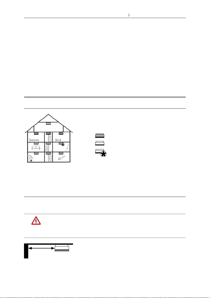
Fig. 1
Minimum equipment
Ideal equipment
Equipment with limitations
Maintain a minimum distance of 50 cm to:
• walls
•lamps
• live wires
≥ 50 cm
The device is only to be used for its intended purpose. Any improper modification or
failure to follow the operating instructions voids any and all warranty and guarantee
claims.
After unpacking the device, check it immediately for possible mechanical damage. If it
has been damaged in transport, inform the supplier immediately.
The device may only be used as a fixed-site installation; that means only when assembled and after conclusion of all installation and operational start-up tasks and only in
the surroundings designated for it.
Elsner Elektronik is not liable for any changes in norms and standards which may occur
after publication of these operating instructions.
2.2. Installation location
2.2.1. Equipping the building with smoke alarms
The minimum protection is the installation of smoke alarms in the bedrooms and halls
and/or corridors to ensure that you are woken up during the night in case of a smoke
alarm. If the building has several floors, at least one smoke alarm should be installed
in the hall on every floor. Please refer to DIN 14676 for further installation guidelines.
2.2.2. Positioning and distances
Install the smoke alarm on the room ceiling. If the smoke alarm is installed in the middle of the room, it has its best detection characteristics.
WARNING!
Mains voltage for in-wall concealed cables!
• If the device is attached by means of screws, first ensure
that there is no power line installed under the assembly point!
Smoke alarm Salva KNX • Version: 09.09.2016 • Technical Changes and Errors excepted.
Page 10
9 Installation and commissioning
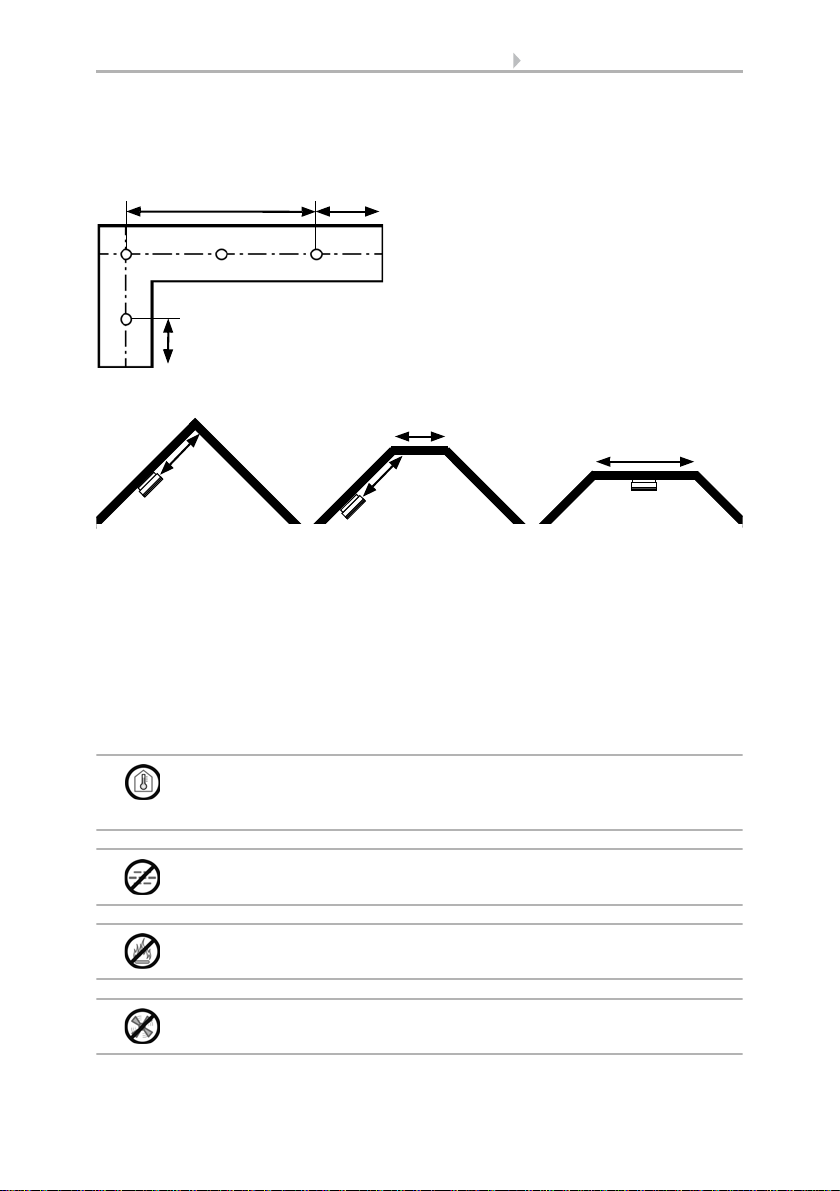
Attach the first alarm at a maximum distance
of 7.50 m to the end of the room in long structures. Distribute at least 3 alarms on 15 m of
corridor. Attach alarms in the middle of corners and crossroads in the corridor.
Halls and corridors:
≤ 15 m ≤ 7,5 m
≤ 7,5 m
x
0,50 m < x < 1 m
x
< 1 m
0,50 m < x < 1 m
≥ 1 m
A + B: For pointed and flat gables with a ceiling area of less than 1 m width: Attach
alarms at a minimum distance of 0.50 m and a maximum distance of 1 m to the top.
C: For flat gables with a ceiling area of more than 1 m width: Attach to the middle of
the ceiling like in other rooms.
ABC
Gables:
Small rooms: If the minimum distance to the wall cannot be maintained, install the
alarm on the wall. Keep a distance of at least 0.50 m and maximum 1 m to the ceiling.
Rooms with a gallery: Attach an additional alarm underneath the gallery if said gallery is longer and wider than 2 m and has more than 16 m².
Segmented ceilings: If there are separate areas in the ceiling with a depth of more
than 0.20 m and an area of more than 32 m² (e.g. due to beams separating the areas),
install an alarm in each area (on the ceiling or on the beams).
The device is only approved for interior spaces. Do not install in rooms
with temperatures of less than -10°C or more than +50°C! Avoid
condensation.
Do not install in rooms in which a high degree of water vapour is
produced under normal circumstances (e.g. kitchen, bathroom, toilet)!
Do not install near places of fire or open fireplaces!
Do not install near ventilation shafts (e.g. of air conditioning or
circulating air systems)!
Smoke alarm Salva KNX • Version: 09.09.2016 • Technical Changes and Errors excepted.
Page 11
10 Installation and commissioning
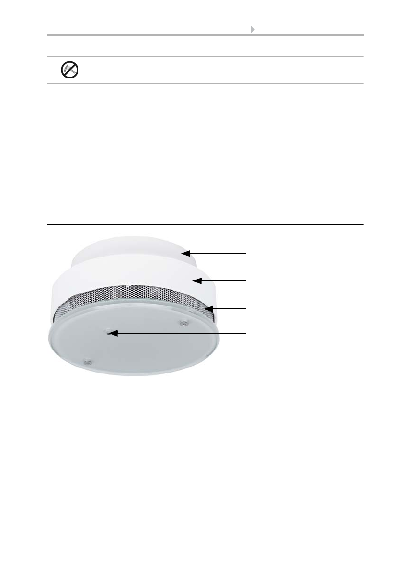
2
Fig. 2
1Skirting
2 Housing with electronics and battery
3 Openings for air circulation
4 Light transmission bar: Red LED for Operating and alarm signals, page 17 and
Push-button for Function test, page 15
3
4
1
Do not paint the smoke alarms!
Avoid the following sources of interference in order to limit distortion of measuring results for temperature, humidity and pressure:
• Direct sunlight
• Draughts from windows and doors
• Warming or cooling of the building structure on which the sensor is mounted,
e.g. due to sunlight, heating or cold water pipes
• Connection lines, which lead from warmer or colder areas to the sensor
Temperature variations from such sources of interference must be corrected in the ETS
in order to ensure the specified accuracy of the sensor (temperature offset).
2.3. Device design
2.3.1. Exterior view
Smoke alarm Salva KNX • Version: 09.09.2016 • Technical Changes and Errors excepted.
Page 12

11 Installation and commissioning
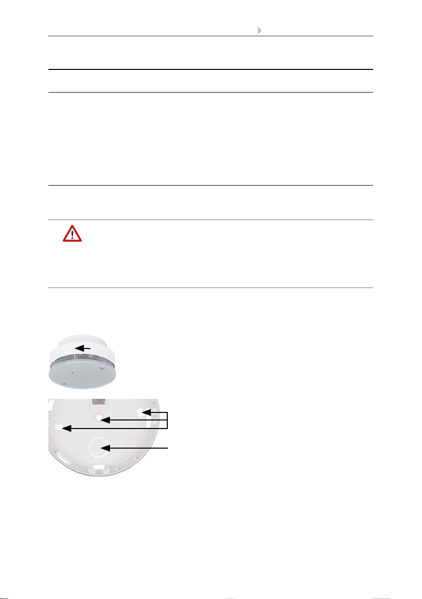
2
Fig. 3
1 Battery assembly lock (the housing cannot be closed without a battery)
2 Fastening opening with 1 screw
3 Openings for fastenings with 2 screws (distance 67 mm)
4 Opening for bus cable
3
4
1
2
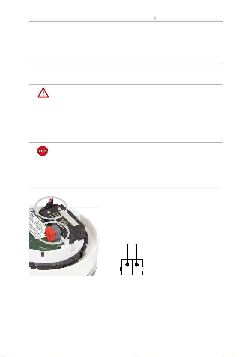
Fig. 4
1Battery
2 KNX terminal
3 LED programming
4 Programming key (recessed) for bus addressing,
see Addressing the equipment, page 14
3
4
1
2.3.2. Skirting
2.3.3. Interior view of the housing
Smoke alarm Salva KNX • Version: 09.09.2016 • Technical Changes and Errors excepted.
Page 13
12 Installation and commissioning
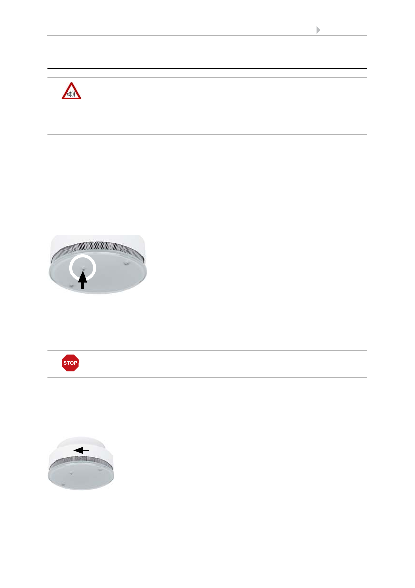
Fig. 5
The housing is removed from the skirting by
turning it anti-clockwise.
Fig. 6
Remove the cover on the opening for the supply line (1) from the skirting and thread the cable through it.
Screw the smoke alarm skirting onto the ceiling (2, openings for screws).
2
1
2.4. Installing the device
2.4.1. Instructions for assembly and initial start-up
Never expose the device to water (e.g. rain) or dust (e.g. drilling dust). This can damage
the electronics and the sensor system. A relative air humidity of 93% may not be exceeded. Avoid condensation.
After the bus voltage has been applied, the device will enter an initialisation phase lasting a few seconds. During this phase no information can be received or sent via the
bus.
2.4.2. Assembly preparation and skirting assembly
Determine the installation point on the room ceiling. Please observe the instructions in
chapter Installation location, page 8 for this.
BEWARE!
Injury hazard in case of improper fastening!
The device may fall and injure people if it is not fastened properly.
• Observe, the carrying capacity of the wall/ceiling material when
selecting the place of installation.
• Use fixing materials that are suitable for the material underneath.
If you are using the screws and dowels provided, use a 6mm drill to drill holes with a
distance of 67 mm (if you are using two screws for installation). Use the skirting of the
smoke alarm as a stencil. Insert the dowels into the drilling holes.
As an alternative, the skirting of the alarm may be attached to the ceiling with doublesided adhesive pad (VdS approved). Carefully check the ceiling surface carefully for
lasting carrying and adhesive capacity before using adhesive pads. If necessary, do a
test glueing application. Optimum adhesive power can only be obtained on a clean surface.
Smoke alarm Salva KNX • Version: 09.09.2016 • Technical Changes and Errors excepted.
Page 14
13 Installation and commissioning
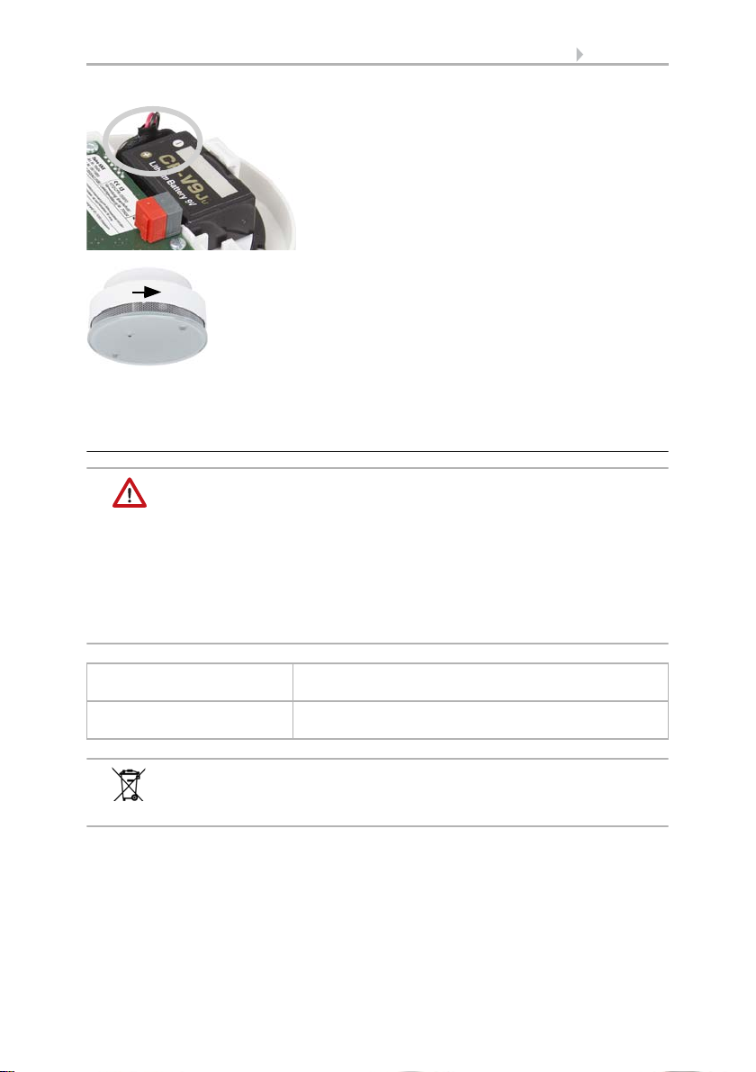
Fig. 7
1. Connect the battery (check for correct polarity!) and insert it into the battery compartment.
2. Connect the device to the KNX bus via the
pluggable terminal (+|-).
1
2
-
+
-
+
KNX
Remove the protective foil form one side of the adhesive pad and attach the pad in the
middle of the alarm skirting. Then remove the protective foil on the other side and attach the skirting by firmly pressing it to the ceiling.
2.4.3. Connection
The supply line of the smoke alarm occurs via a 9 V battery. In addition, the KNX module receives the bus voltage via the KNX terminal.
WARNING!
Danger of explosion in case of improper handling of the battery!
Property damage by battery leakage.
• Do not recharge batteries.
• Do not short-circuit batteries.
• Do not force batteries open or damage them
• Do not bring batteries in contact with fire, water or high
temperatures.
ATTENTION!
Do not use rechargeable batteries or mains units for voltage
supply!
• In case of mains voltage, the device would be out of order
if the mains is out and could not signal any fire.
• The lower rechargeable battery voltage would trigger
a low battery capacity alarm.
Smoke alarm Salva KNX • Version: 09.09.2016 • Technical Changes and Errors excepted.
Page 15
14 Addressing the equipment
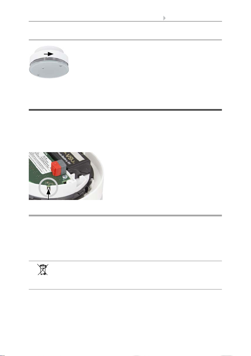
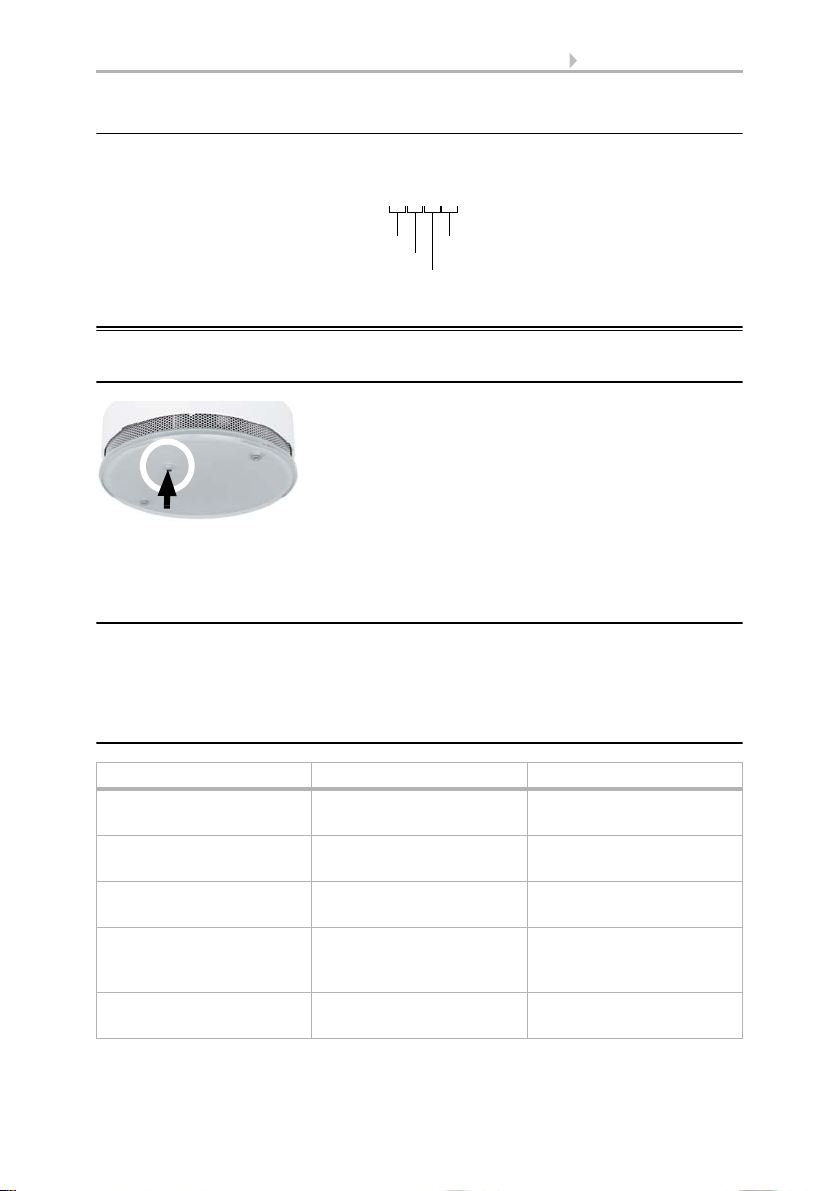
Fig. 8
Place the housing onto the skirting and fasten
it by turning it clockwise.
Fig. 9
Use a thin object to reach the button, e.g. a
wire.
2.4.4. Completing the installation
Check if the LED is flashing and conduct a function test.
> Function test, page 15
3. Addressing the equipment
The equipment is delivered with the bus address 15.15.250. You can program a different address in the ETS by overwriting the address 15.15.250 or by teaching the device
via the programming button.
The programming button is on the inside of the housing. The housing is removed from
the skirting by turning it anti-clockwise, and fixed in place by turning clockwise.
4. Maintenance
In some German federal states, the owner of houses and flats are responsible for the
installation and functioning of smoke alarms according to LBO (State construction
laws) (see www.rauchmelder-lebensretter.de). Maintenance has to be conducted at
least annually and, according to DIN 14676 includes a visual inspection, a function test
and, if required, a battery change. A function test also has to be conducted after any
longer absence, at ,after 1 year at the latest.
The used battery and the device must be disposed of correctly so that
valuable resources may be recycled. Neither the battery nor the device
may be disposed of together with domestic or company
waste.
Smoke alarm Salva KNX • Version: 09.09.2016 • Technical Changes and Errors excepted.
Page 16
15 Maintenance
Fig. 10
Press the light transmission bar for at least 1
second.
Fig. 11
Separate the smoke alarm from the skirting
by turning it anti-clockwise.
4.1. Function test
BEWARE!
Danger of hearing damage!
During the function test (pressing on the light transmission bar),
a loud, shrill tone is sounded (at least 85 dB).
• Keep a minimum distance of 50 cm between smoke alarm and ear.
1. Conducting a visual inspection:
Check:
• Is the device found at the expected position?
• Are the smoke entry openings clean? - Remove dust if necessary. The device
must not be painted over.
• Is the device free from mechanical damage? - Replace the device if it is
damaged.
2. Conducting a function test:
If the function test is successful, a signal tone sounds. The smoke alarm works properly. If there is no signal tone, the device is not functioning. In this case, replace the battery and conduct the function test again. If there is still no signal tone, the device is defect and must be replaced.
Smoke alarms must be replaced with new devices after a maximum
period of 10 years according to DIN 14604.
4.2. Replace the battery
The device is supplied with 9 V voltage from a battery. Lack of battery capacity is signalled optically and acoustically for 30 days and transmitted to the bus.
Smoke alarm Salva KNX • Version: 09.09.2016 • Technical Changes and Errors excepted.
Page 17
16 Maintenance
Fig. 12
Connect the new battery to the smoke alarm
(check for correct polarity!) and insert it into
the battery compartment.
Fig. 13
Place the housing with the new battery onto
the skirting and fasten it by turning it clockwise.
Check if the LED is flashing and conduct a function test.
> Function test, page 15
4.2.1. Types of batteries
WARNING!
Danger of explosion in case of improper handling of the battery!
• Only replace with a lithium battery type DFK CP-V9Ju.
• Do not use rechargeable batteries or mains units for voltage supply
to ensure a sufficiently high voltage and supply even in case
of a mains outage.
• Do not recharge batteries and do not short-circuit them.
• Do not force batteries open or damage them and do not
bring them into contact with fire, water or high temperatures.
Approved battery type FDK CP-V9Ju
Average service life approx. 10 years (typical),
Only use lithium batteries
under normal conditions as per EN 14604
The used battery and the device must be disposed of properly so that
valuable resources may be recycled. Neither the battery nor the device
may be disposed of together with domestic or company waste.
Smoke alarm Salva KNX • Version: 09.09.2016 • Technical Changes and Errors excepted.
Page 18
17 Device alarm functions
Ser.no. 15111801
Year of production
-month
-day
Device number
Fig. 14
The alarm can be muted by pressing the
flashing light transmission bar.
4.2.2. Serial number
The serial number on the type plate inside the device contains the production data and
device number:
5. Device alarm functions
5.1. Alarm mute (acknowledgement)
In this case, only the LED continues to flash every 10 seconds. After about 10 minutes,
the devices switches back to normal operating mode.
5.2. Alarm memory
An alarm is saved in the device for 24 hours. During this time, the LED briefly flashes
3 times every 43 seconds. The alarm memory can be reset by pressing the light transmission bar (red LED) once.
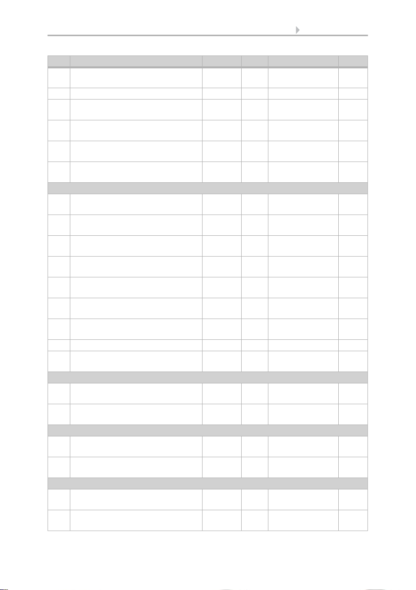
5.3. Operating and alarm signals
Function / meaning Signal tone Red LED
Normal operating mode
(automatic self-test)
Alarm status Loud interval tone in
Fault / dirt Short signal tone 3 times
Battery exchange display 1x Short signal tone
Alarm mute (acknowledgement)
Smoke alarm Salva KNX • Version: 09.09.2016 • Technical Changes and Errors excepted.
No sound Flashes every 40 seconds
0.5 second rhythm
every 40 seconds
every 40 seconds
No sound Flashes every 10 seconds
Flashing twice per second
LED off
Flashes every 40 seconds
together with the signal
tone
Page 19

18 Device alarm functions
Function / meaning Signal tone Red LED
Alarm memory active
(i.e. there was an alarm
No sound Flashes 3 times every 43
seconds
state during the previous
24 hours)
Function test Loud interval tone Flashing twice per second
while the light transmis-
sion bar
is pressed
Smoke alarm Salva KNX • Version: 09.09.2016 • Technical Changes and Errors excepted.
Page 20

19 Transfer protocol
6. Transfer protocol
Units:
Temperatures in degrees Celsius
Air humidity in %
Absolute air humidity in g/kg and/or g/m
Variables in %
6.1. List of all communication objects
Abbreviation flags:
C Communication
R Read
WWrite
T Transfer
UUpdate
No. Text Function Flags DPT type Size
For all models:
1 Software version Output R-CT [217.1] DPT_Ver-
For Salva KNX TH only:
41 Temperature sensor: Malfunction Output R-CT [1.1] DPT_Switch 1 bit
42 Temperature sensor: External
measurement
43 Temperature sensor: Measured
value
44 Temperature sensor: Total
measurement
45 Temperature sensor: Min./Max.
measurement query
46 Temperature sensor: Minimum
measurement
47 Temperature sensor: Maximum
measurement
48 Temperature sensor: Min./Max.
measurement reset
51 Temp. threshold value 1: Absolute
value
52 Temp. threshold value 1: (1:+ | 0:-) Input -WC- [1.1] DPT_Switch 1 bit
53 Temp. threshold value 1: Switching
delay from 0 to 1
54 Temp. threshold value 1: Switching
delay from 1 to 0
3
sion
Input -WCT [9.1] DPT_Val-
Output R-CT [9.1] DPT_Val-
Output R-CT [9.1] DPT_Val-
Input -WC- [1.017] DPT_Trig-
Output R-CT [9.1] DPT_Val-
Output R-CT [9.1] DPT_Val-
Input -WC- [1.017] DPT_Trig-
Input/
Output
Input -WC- [7.5] DPT_TimePe-
Input -WC- [7.5] DPT_TimePe-
ue_Temp
ue_Temp
ue_Temp
ger
ue_Temp
ue_Temp
ger
RWCT [9.1] DPT_Val-
ue_Temp
riodSec
riodSec
2 bytes
2 bytes
2 bytes
2 bytes
1 bit
2 bytes
2 bytes
1 bit
2 bytes
2 bytes
2 bytes
Smoke alarm Salva KNX • Version: 09.09.2016 • Technical Changes and Errors excepted.
Page 21

20 Transfer protocol
No. Text Function Flags DPT type Size
55 Temp. threshold value 1: Switching
Output R-CT [1.1] DPT_Switch 1 bit
output
56 Temp. threshold value 1: Switching
Input -WC- [1.1] DPT_Switch 1 bit
output block
58 Temp. threshold value 2: Absolute
value
Input/
Output
RWCT [9.1] DPT_Val-
ue_Temp
2 bytes
59 Temp. threshold value 2: (1:+ | 0:-) Input -WC- [1.1] DPT_Switch 1 bit
60 Temp. threshold value 2: Switching
delay from 0 to 1
61 Temp. threshold value 2: Switching
delay from 1 to 0
62 Temp. threshold value 2: Switching
Input -WC- [7.5] DPT_TimePe-
2 bytes
riodSec
Input -WC- [7.5] DPT_TimePe-
2 bytes
riodSec
Output R-CT [1.1] DPT_Switch 1 bit
output
63 Temp. threshold value 2: Switching
Input -WC- [1.1] DPT_Switch 1 bit
output block
65 Temp. threshold value 3: Absolute
value
Input/
Output
RWCT [9.1] DPT_Val-
ue_Temp
2 bytes
66 Temp. threshold value 3: (1:+ | 0:-) Input -WC- [1.1] DPT_Switch 1 bit
67 Temp. threshold value 3: Switching
delay from 0 to 1
68 Temp. threshold value 3: Switching
delay from 1 to 0
69 Temp. threshold value 3: Switching
Input -WC- [7.5] DPT_TimePe-
2 bytes
riodSec
Input -WC- [7.5] DPT_TimePe-
2 bytes
riodSec
Output R-CT [1.1] DPT_Switch 1 bit
output
70 Temp. threshold value 3: Switching
Input -WC- [1.1] DPT_Switch 1 bit
output block
72 Temp. threshold value 4: Absolute
value
Input/
Output
RWCT [9.1] DPT_Val-
ue_Temp
2 bytes
73 Temp. threshold value 4: (1:+ | 0:-) Input -WC- [1.1] DPT_Switch 1 bit
74 Temp. threshold value 4: Switching
delay from 0 to 1
75 Temp. threshold value 4: Switching
delay from 1 to 0
76 Temp. threshold value 4: Switching
Input -WC- [7.5] DPT_TimePe-
2 bytes
riodSec
Input -WC- [7.5] DPT_TimePe-
2 bytes
riodSec
Output R-CT [1.1] DPT_Switch 1 bit
output
77 Temp. threshold value 4: Switching
Input -WC- [1.1] DPT_Switch 1 bit
output block
For Salva KNX TH only:
311 Humidity sensor: Malfunction Output R-CT [1.1] DPT_Switch 1 bit
314 Humidity sensor: External
measurement
315 Humidity sensor: Measured value Output R-CT [9.7] DPT_Val-
Input -WCT [9.7] DPT_Val-
ue_Humidity
2 bytes
2 bytes
ue_Humidity
Smoke alarm Salva KNX • Version: 09.09.2016 • Technical Changes and Errors excepted.
Page 22

21 Transfer protocol
No. Text Function Flags DPT type Size
316 Humidity sensor: Total
measurement
317 Humidity sensor: Min./Max.
measurement query
318 Humidity sensor: Minimum
measurement
319 Humidity sensor: Maximum
measurement
320 Humidity sensor: Min./Max.
measurement reset
331 Humidity threshold value 1:
Absolute value
Output R-CT [9.7] DPT_Val-
ue_Humidity
Input -WC- [1.017] DPT_Trig-
ger
Output R-CT [9.7] DPT_Val-
ue_Humidity
Output R-CT [9.7] DPT_Val-
ue_Humidity
Input -WC- [1.017] DPT_Trig-
ger
Input/
Output
RWCT [9.7] DPT_Val-
ue_Humidity
2 bytes
1 bit
2 bytes
2 bytes
1 bit
2 bytes
332 Humidity threshold value 1: (1:+|0:-) Input -WC- [1.1] DPT_Switch 1 bit
333 Humidity threshold value 1: Delay
from 0 to 1
334 Humidity threshold value 1: Delay
from 1 to 0
335 Humidity threshold value 1:
Input -WC- [7.5] DPT_TimePe-
2 bytes
riodSec
Input -WC- [7.5] DPT_TimePe-
2 bytes
riodSec
Output R-CT [1.1] DPT_Switch 1 bit
Switching output
336 Humidity threshold value 1:
Input -WC- [1.1] DPT_Switch 1 bit
Switching output block
337 Humidity threshold value 2:
Absolute value
Input/
Output
RWCT [9.7] DPT_Val-
ue_Humidity
2 bytes
338 Humidity threshold value 2: (1:+|0:-) Input -WC- [1.1] DPT_Switch 1 bit
339 Humidity threshold value 2:
Delay from 0 to 1
340 Humidity threshold value 2:
Delay from 1 to 0
341 Humidity threshold value 2:
Input -WC- [7.5] DPT_TimePe-
2 bytes
riodSec
Input -WC- [7.5] DPT_TimePe-
2 bytes
riodSec
Output R-CT [1.1] DPT_Switch 1 bit
Switching output
342 Humidity threshold value 2:
Input -WC- [1.1] DPT_Switch 1 bit
Switching output block
343 Humidity threshold value 3:
Absolute value
Input/
Output
RWCT [9.7] DPT_Val-
ue_Humidity
2 bytes
344 Humidity threshold value 3: (1:+|0:-) Input -WC- [1.1] DPT_Switch 1 bit
345 Humidity threshold value 3:
Delay from 0 to 1
346 Humidity threshold value 3:
Delay from 1 to 0
347 Humidity threshold value 3:
Input -WC- [7.5] DPT_TimePe-
2 bytes
riodSec
Input -WC- [7.5] DPT_TimePe-
2 bytes
riodSec
Output R-CT [1.1] DPT_Switch 1 bit
Switching output
348 Humidity threshold value 3:
Input -WC- [1.1] DPT_Switch 1 bit
Switching output block
Smoke alarm Salva KNX • Version: 09.09.2016 • Technical Changes and Errors excepted.
Page 23
22 Transfer protocol
No. Text Function Flags DPT type Size
349 Humidity threshold value 4:
Absolute value
Input/
Output
RWCT [9.7] DPT_Val-
ue_Humidity
2 bytes
350 Humidity threshold value 4: (1:+|0:-) Input -WC- [1.1] DPT_Switch 1 bit
351 Humidity threshold value 4:
Delay from 0 to 1
352 Humidity threshold value 4:
Delay from 1 to 0
353 Humidity threshold value 4:
Input -WC- [7.5] DPT_TimePe-
2 bytes
riodSec
Input -WC- [7.5] DPT_TimePe-
2 bytes
riodSec
Output R-CT [1.1] DPT_Switch 1 bit
Switching output
354 Humidity threshold value 4:
Input -WC- [1.1] DPT_Switch 1 bit
Switching output block
For Salva KNX TH only:
381 Dewpoint: Measured value Output R-CT [9.1] DPT_Val-
2 bytes
ue_Temp
382 Coolant temp.: Threshold value Output R-CT [9.1] DPT_Val-
2 bytes
ue_Temp
383 Coolant temp.: Actual value Input RWCT [9.1] DPT_Val-
2 bytes
ue_Temp
384 Coolant temp.: Offset change
Input -WC- [1.1] DPT_Switch 1 bit
(1:+ | 0:-)
385 Coolant temp.: Current offset Output R-CT [9.1] DPT_Val-
2 bytes
ue_Temp
386 Coolant temp.: Switching delay from
0 to 1
387 Coolant temp.: Switching delay from
1 to 0
Input -WC- [7.5] DPT_TimePe-
riodSec
Input -WC- [7.5] DPT_TimePe-
riodSec
2 bytes
2 bytes
388 Coolant temp.: Switching output Output R-CT [1.1] DPT_Switch 1 bit
389 Coolant temp.: Switching output
Input -WC- [1.1] DPT_Switch 1 bit
block
For Salva KNX TH only:
391 Absolute humidity [g/kg] Output R-CT [14.5] DPT_Val-
4 bytes
ue_Amplitude
392 Absolute humidity [g/m²] Output R-CT [14.17] DPT_Val-
4 bytes
ue_Density
For Salva KNX TH only:
394 Ambient climate status:
Output R-CT [1.1] DPT_Switch 1 bit
1 = comfortable | 0 = uncomfortable
395 Ambient climate status: Text Output R-CT [16.0]
DPT_String_ASCII
14
bytes
For Salva KNX TH only:
482 Temp. controller: HVAC mode
(priority 2)
483 Temp. controller: Mode frost/heat
Input RWCT [20.102] DPT_H-
1 byte
VACMode
Input RWCT [1.1] DPT_Switch 1 bit
protection activation
Smoke alarm Salva KNX • Version: 09.09.2016 • Technical Changes and Errors excepted.
Page 24

23 Transfer protocol
No. Text Function Flags DPT type Size
484 Temp. controller: Block
Input -WC- [1.1] DPT_Switch 1 bit
(1 = Blocking)
485 Temp. controller: Current setpoint Output R-CT [9.1] DPT_Val-
2 bytes
ue_Temp
486 Temp. controller: Switching
Input -WC- [1.1] DPT_Switch 1 bit
(0: Heating | 1: Cooling)
487 Temp. controller: Setpoint comfort
heating
488 Temp. controller: Setpoint comfort
Input/
Output
RWCT [9.1] DPT_Val-
ue_Temp
2 bytes
Input -WC- [1.1] DPT_Switch 1 bit
heating (1:+ | 0: -)
489 Temp. controller: Setpoint comfort
cooling
490 Temp. controller: Setpoint comfort
Input/
Output
RWCT [9.1] DPT_Val-
ue_Temp
2 bytes
Input -WC- [1.1] DPT_Switch 1 bit
cooling (1:+ | 0: -)
491 Temp. controller: Basic 16-bit
setpoint shift
492 Temp. controller: Setpoint standby
heating
493 Temp. controller: Setpoint standby
Input/
Output
Input/
Output
RWCT [9.1] DPT_Val-
ue_Temp
RWCT [9.1] DPT_Val-
ue_Temp
2 bytes
2 bytes
Input -WC- [1.1] DPT_Switch 1 bit
heating (1:+ | 0: -)
494 Temp. controller: Setpoint standby
cooling
495 Temp. controller: Setpoint standby
Input/
Output
RWCT [9.1] DPT_Val-
ue_Temp
2 bytes
Input -WC- [1.1] DPT_Switch 1 bit
cooling (1:+ | 0: -)
496 Temp. controller: Setpoint eco
heating
497 Temp. controller: Setpoint, eco
Input/
Output
RWCT [9.1] DPT_Val-
ue_Temp
2 bytes
Input -WC- [1.1] DPT_Switch 1 bit
heating (1:+ | 0: -)
498 Temp. controller: Setpoint eco
cooling
499 Temp. controller: Setpoint, eco
Input/
Output
RWCT [9.1] DPT_Val-
ue_Temp
2 bytes
Input -WC- [1.1] DPT_Switch 1 bit
cooling (1:+ | 0: -)
500 Temp. controller: Control variable,
Output R-CT [5.1] DPT_Scaling 1 byte
heating (level 1)
501 Temp. controller: Control variable,
Output R-CT [5.1] DPT_Scaling 1 byte
heating (level 2)
502 Temp. controller: Control variable,
Output R-CT [5.1] DPT_Scaling 1 byte
cooling (level 1)
503 Temp. controller: Control variable,
Output R-CT [5.1] DPT_Scaling 1 byte
cooling (level 2)
482 Temp. controller: HVAC mode
(priority 2)
504 Temperature controller: Variable for
Input RWCT [20.102] DPT_H-
1 byte
VACMode
Output R-CT [5.1] DPT_Scaling 1 byte
4/6-way valve
Smoke alarm Salva KNX • Version: 09.09.2016 • Technical Changes and Errors excepted.
Page 25

24 Transfer protocol
No. Text Function Flags DPT type Size
505 Temp. controller: Status heating
Output R-CT [1.1] DPT_Switch 1 bit
level 1 (1:ON | 0:OFF)
506 Temp. controller: Status heating
Output R-CT [1.1] DPT_Switch 1 bit
level 2 (1:ON | 0:OFF)
507 Temp. controller: Status cooling
Output R-CT [1.1] DPT_Switch 1 bit
level 1 (1:ON | 0:OFF)
508 Temp. controller: Status cooling
Output R-CT [1.1] DPT_Switch 1 bit
level 2 (1:ON | 0:OFF)
509 Temp. controller: Comfort extension
status
510 Temp. controller: Comfort extension
time
Input/
RWCT [1.1] DPT_Switch 1 bit
Output
Input RWCT [7.5] DPT_TimePe-
riodSec
2 bytes
For Salva KNX TH only:
515 Summer Compensation: Outside
temperature
516 Summer Compensation: Setpoint
value
517 Summer Compensation: Block
Input -WCT [9.1] DPT_Val-
2 bytes
ue_Temp
Output R-CT [9.1] DPT_Val-
2 bytes
ue_Temp
Input -WC- [1.1] DPT_Switch 1 bit
(1 = Blocking)
For Salva KNX TH only:
521 Humidity controller: Block (1: block) Input -WC- [1.2] DPT_Bool 1 bit
522 Humidity controller: Setpoint value Input/
Output
523 Humidity controller: Setpoint
Input -WC- [1.2] DPT_Bool 1 bit
RWCT [9,007] DPT_Val-
ue_Humidity
2 bytes
value (1:+ | 0:-)
524 Humidity controller: Control variable
Output R-CT [5.1] DPT_Scaling 1 byte
dehumidification
525 Humidity controller: Control variable
Output R-CT [5.1] DPT_Scaling 1 byte
dehumidification level 2
526 Humidity controller: Control variable
Output R-CT [5.1] DPT_Scaling 1 byte
humidification
527 Humidity controller:
Output R-CT [1.1] DPT_Switch 1 bit
Dehumidification status (1:ON |
0:OFF)
528 Humidity controller:
Output R-CT [1.1] DPT_Switch 1 bit
Dehumidification 2 status (1:ON |
0:OFF)
529 Humidity controller: Humidification
Output R-CT [1.1] DPT_Switch 1 bit
status (1:ON | 0:OFF)
For all models:
1111 Control variable comparator 1:
Input -WC- [5.1] DPT_Scaling 1 byte
Input 1
1112 Control variable comparator 1:
Input -WC- [5.1] DPT_Scaling 1 byte
Input 2
Smoke alarm Salva KNX • Version: 09.09.2016 • Technical Changes and Errors excepted.
Page 26

25 Transfer protocol
No. Text Function Flags DPT type Size
1113 Control variable comparator 1:
Input -WC- [5.1] DPT_Scaling 1 byte
Input 3
1114 Control variable comparator 1:
Input -WC- [5.1] DPT_Scaling 1 byte
Input 4
1115 Control variable comparator 1:
Input -WC- [5.1] DPT_Scaling 1 byte
Input 5
1116 Control variable comparator 1:
Output R-CT [5.1] DPT_Scaling 1 byte
Output
1117 Control variable comparator 1:
Output -WC- [1.2] DPT_Bool 1 bit
Block: block)
1118 Control variable comparator 2:
Input -WC- [5.1] DPT_Scaling 1 byte
Input 1
1119 Control variable comparator 2:
Input -WC- [5.1] DPT_Scaling 1 byte
Input 2
1120 Control variable comparator 2:
Input -WC- [5.1] DPT_Scaling 1 byte
Input 3
1121 Control variable comparator 2:
Input -WC- [5.1] DPT_Scaling 1 byte
Input 4
1122 Control variable comparator 2:
Input -WC- [5.1] DPT_Scaling 1 byte
Input 5
1123 Control variable comparator 2:
Output R-CT [5.1] DPT_Scaling 1 byte
Output
1124 Control variable comparator 2:
Output -WC- [1.2] DPT_Bool 1 bit
Block (1: block)
1125 Control variable comparator 3:
Input -WC- [5.1] DPT_Scaling 1 byte
Input 1
1126 Control variable comparator 3:
Input -WC- [5.1] DPT_Scaling 1 byte
Input 2
1127 Control variable comparator 3:
Input -WC- [5.1] DPT_Scaling 1 byte
Input 3
1128 Control variable comparator 3:
Input -WC- [5.1] DPT_Scaling 1 byte
Input 4
1129 Control variable comparator 3:
Input -WC- [5.1] DPT_Scaling 1 byte
Input 5
1130 Control variable comparator 3:
Output R-CT [5.1] DPT_Scaling 1 byte
Output
1131 Control variable comparator 3:
Output -WC- [1.2] DPT_Bool 1 bit
Block (1: block)
1132 Control variable comparator 4:
Input -WC- [5.1] DPT_Scaling 1 byte
Input 1
1133 Control variable comparator 4:
Input -WC- [5.1] DPT_Scaling 1 byte
Input 2
1134 Control variable comparator 4:
Input -WC- [5.1] DPT_Scaling 1 byte
Input 3
Smoke alarm Salva KNX • Version: 09.09.2016 • Technical Changes and Errors excepted.
Page 27

26 Transfer protocol
No. Text Function Flags DPT type Size
1135 Control variable comparator 4:
Input -WC- [5.1] DPT_Scaling 1 byte
Input 4
1136 Control variable comparator 4:
Input -WC- [5.1] DPT_Scaling 1 byte
Input 5
1137 Control variable comparator 4:
Output R-CT [5.1] DPT_Scaling 1 byte
Output
1138 Control variable comparator 4:
Output -WC- [1.2] DPT_Bool 1 bit
Block (1: block)
For all models:
1141 Computer 1: Input I1 Input RWCT Dep. on setting 4 bytes
1142 Computer 1: Input I2 Input RWCT Dep. on setting 4 bytes
1143 Computer 1: Input I3 Input RWCT Dep. on setting 4 bytes
1144 Computer 1: Output O1 Output R-CT Dep. on setting 4 bytes
1145 Computer 1: Output O2 Output R-CT Dep. on setting 4 bytes
1146 Computer 1: Condition text Output R-CT [16.0]
DPT_String_ASCII
14
bytes
1147 Computer 1: Monitoring status Output R-CT [1.1] DPT_Switch 1 bit
1148 Computer 1: Block (1: block) Input -WC- [1.1] DPT_Switch 1 bit
1149 Computer 2: Input I1 Input RWCT Dep. on setting 4 bytes
1150 Computer 2: Input I2 Input RWCT Dep. on setting 4 bytes
1151 Computer 2: Input I3 Input RWCT Dep. on setting 4 bytes
1152 Computer 2: Output O1 Output R-CT Dep. on setting 4 bytes
1153 Computer 2: Output O2 Output R-CT Dep. on setting 4 bytes
1154 Computer 2: Condition text Output R-CT [16.0]
DPT_String_ASCII
14
bytes
1155 Computer 2: Monitoring status Output R-CT [1.1] DPT_Switch 1 bit
1156 Computer 2: Block (1: block) Input -WC- [1.1] DPT_Switch 1 bit
1157 Computer 3: Input I1 Input RWCT Dep. on setting 4 bytes
1158 Computer 3: Input I2 Input RWCT Dep. on setting 4 bytes
1159 Computer 3: Input I3 Input RWCT Dep. on setting 4 bytes
1160 Computer 3: Output O1 Output R-CT Dep. on setting 4 bytes
1161 Computer 3: Output O2 Output R-CT Dep. on setting 4 bytes
1162 Computer 3: Condition text Output R-CT [16.0]
DPT_String_ASCII
14
bytes
1163 Computer 3: Monitoring status Output R-CT [1.1] DPT_Switch 1 bit
1164 Computer 3: Block (1: block) Input -WC- [1.1] DPT_Switch 1 bit
1165 Computer 4: Input I1 Input RWCT Dep. on setting 4 bytes
1166 Computer 4: Input I2 Input RWCT Dep. on setting 4 bytes
1167 Computer 4: Input I3 Input RWCT Dep. on setting 4 bytes
1168 Computer 4: Output O1 Output R-CT Dep. on setting 4 bytes
1169 Computer 4: Output O2 Output R-CT Dep. on setting 4 bytes
Smoke alarm Salva KNX • Version: 09.09.2016 • Technical Changes and Errors excepted.
Page 28

27 Transfer protocol
No. Text Function Flags DPT type Size
1170 Computer 4: Condition text Output R-CT [16.0]
DPT_String_ASCII
14
bytes
1171 Computer 4: Monitoring status Output R-CT [1.1] DPT_Switch 1 bit
1172 Computer 4: Block (1: block) Input -WC- [1.1] DPT_Switch 1 bit
1173 Computer 5: Input I1 Input RWCT Dep. on setting 4 bytes
1174 Computer 5: Input I2 Input RWCT Dep. on setting 4 bytes
1175 Computer 5: Input I3 Input RWCT Dep. on setting 4 bytes
1176 Computer 5: Output O1 Output R-CT Dep. on setting 4 bytes
1177 Computer 5: Output O2 Output R-CT Dep. on setting 4 bytes
1178 Computer 5: Condition text Output R-CT [16.0]
DPT_String_ASCII
14
bytes
1179 Computer 5: Monitoring status Output R-CT [1.1] DPT_Switch 1 bit
1180 Computer 5: Block (1: block) Input -WC- [1.1] DPT_Switch 1 bit
1181 Computer 6: Input I1 Input RWCT Dep. on setting 4 bytes
1182 Computer 6: Input I2 Input RWCT Dep. on setting 4 bytes
1183 Computer 6: Input I3 Input RWCT Dep. on setting 4 bytes
1184 Computer 6: Output O1 Output R-CT Dep. on setting 4 bytes
1185 Computer 6: Output O2 Output R-CT Dep. on setting 4 bytes
1186 Computer 6: Condition text Output R-CT [16.0]
DPT_String_ASCII
14
bytes
1187 Computer 6: Monitoring status Output R-CT [1.1] DPT_Switch 1 bit
1188 Computer 6: Block (1: block) Input -WC- [1.1] DPT_Switch 1 bit
1189 Computer 7: Input I1 Input RWCT Dep. on setting 4 bytes
1190 Computer 7: Input I2 Input RWCT Dep. on setting 4 bytes
1191 Computer 7: Input I3 Input RWCT Dep. on setting 4 bytes
1192 Computer 7: Output O1 Output R-CT Dep. on setting 4 bytes
1193 Computer 7: Output O2 Output R-CT Dep. on setting 4 bytes
1194 Computer 7: Condition text Output R-CT [16.0]
DPT_String_ASCII
14
bytes
1195 Computer 7: Monitoring status Output R-CT [1.1] DPT_Switch 1 bit
1196 Computer 7: Block (1: block) Input -WC- [1.1] DPT_Switch 1 bit
1197 Computer 8: Input I1 Input RWCT Dep. on setting 4 bytes
1198 Computer 8: Input I2 Input RWCT Dep. on setting 4 bytes
1199 Computer 8: Input I3 Input RWCT Dep. on setting 4 bytes
1200 Computer 8: Output O1 Output R-CT Dep. on setting 4 bytes
1201 Computer 8: Output O2 Output R-CT Dep. on setting 4 bytes
1202 Computer 8: Condition text Output R-CT [16.0]
DPT_String_ASCII
14
bytes
1203 Computer 8: Monitoring status Output R-CT [1.1] DPT_Switch 1 bit
1204 Computer 8: Block (1: block) Input -WC- [1.1] DPT_Switch 1 bit
For all models:
Smoke alarm Salva KNX • Version: 09.09.2016 • Technical Changes and Errors excepted.
Page 29

28 Transfer protocol
No. Text Function Flags DPT type Size
1391 Logic input 1 Input -WC- [1.2] DPT_Bool 1 bit
1392 Logic input 2 Input -WC- [1.2] DPT_Bool 1 bit
1393 Logic input 3 Input -WC- [1.2] DPT_Bool 1 bit
1394 Logic input 4 Input -WC- [1.2] DPT_Bool 1 bit
1395 Logic input 5 Input -WC- [1.2] DPT_Bool 1 bit
1396 Logic input 6 Input -WC- [1.2] DPT_Bool 1 bit
1397 Logic input 7 Input -WC- [1.2] DPT_Bool 1 bit
1398 Logic input 8 Input -WC- [1.2] DPT_Bool 1 bit
1399 Logic input 9 Input -WC- [1.2] DPT_Bool 1 bit
1400 Logic input 10 Input -WC- [1.2] DPT_Bool 1 bit
1401 Logic input 11 Input -WC- [1.2] DPT_Bool 1 bit
1402 Logic input 12 Input -WC- [1.2] DPT_Bool 1 bit
1403 Logic input 13 Input -WC- [1.2] DPT_Bool 1 bit
1404 Logic input 14 Input -WC- [1.2] DPT_Bool 1 bit
1405 Logic input 15 Input -WC- [1.2] DPT_Bool 1 bit
1406 Logic input 16 Input -WC- [1.2] DPT_Bool 1 bit
1411 AND logic 1: 1-bit switching output Output R-CT [1.2] DPT_Bool 1 bit
1412 AND logic 1: 8-bit output A Output R-CT [5.10] DPT_-
1 byte
Value_1_Ucount
1413 AND logic 1: 8-bit output B Output R-CT [5.10] DPT_-
1 byte
Value_1_Ucount
1414 AND logic 1: Block Input -WC- [1.1] DPT_Switch 1 bit
1415 AND logic 2: 1-bit switching output Output R-CT [1.2] DPT_Bool 1 bit
1416 AND logic 2: 8-bit output A Output R-CT [5.10] DPT_-
1 byte
Value_1_Ucount
1417 AND logic 2: 8-bit output B Output R-CT [5.10] DPT_-
1 byte
Value_1_Ucount
1418 AND logic 2: Block Input -WC- [1.1] DPT_Switch 1 bit
1419 AND logic 3: 1-bit switching output Output R-CT [1.2] DPT_Bool 1 bit
1420 AND logic 3: 8-bit output A Output R-CT [5.10] DPT_-
1 byte
Value_1_Ucount
1421 AND logic 3: 8-bit output B Output R-CT [5.10] DPT_-
1 byte
Value_1_Ucount
1422 AND logic 3: Block Input -WC- [1.1] DPT_Switch 1 bit
1423 AND logic 4: 1-bit switching output Output R-CT [1.2] DPT_Bool 1 bit
1424 AND logic 4: 8-bit output A Output R-CT [5.10] DPT_-
1 byte
Value_1_Ucount
1425 AND logic 4: 8-bit output B Output R-CT [5.10] DPT_-
1 byte
Value_1_Ucount
1426 AND logic 4: Block Input -WC- [1.1] DPT_Switch 1 bit
1427 AND logic 5: 1-bit switching output Output R-CT [1.2] DPT_Bool 1 bit
Smoke alarm Salva KNX • Version: 09.09.2016 • Technical Changes and Errors excepted.
Page 30

29 Transfer protocol
No. Text Function Flags DPT type Size
1428 AND logic 5: 8-bit output A Output R-CT [5.10] DPT_-
1 byte
Value_1_Ucount
1429 AND logic 5: 8-bit output B Output R-CT [5.10] DPT_-
1 byte
Value_1_Ucount
1430 AND logic 5: Block Input -WC- [1.1] DPT_Switch 1 bit
1431 AND logic 6: 1-bit switching output Output R-CT [1.2] DPT_Bool 1 bit
1432 AND logic 6: 8-bit output A Output R-CT [5.10] DPT_-
1 byte
Value_1_Ucount
1433 AND logic 6: 8-bit output B Output R-CT [5.10] DPT_-
1 byte
Value_1_Ucount
1434 AND logic 6: Block Input -WC- [1.1] DPT_Switch 1 bit
1435 AND logic 7: 1-bit switching output Output R-CT [1.2] DPT_Bool 1 bit
1436 AND logic 7: 8-bit output A Output R-CT [5.10] DPT_-
1 byte
Value_1_Ucount
1437 AND logic 7: 8-bit output B Output R-CT [5.10] DPT_-
1 byte
Value_1_Ucount
1438 AND logic 7: Block Input -WC- [1.1] DPT_Switch 1 bit
1439 AND logic 8: 1-bit switching output Output R-CT [1.2] DPT_Bool 1 bit
1440 AND logic 8: 8-bit output A Output R-CT [5.10] DPT_-
1 byte
Value_1_Ucount
1441 AND logic 8: 8-bit output B Output R-CT [5.10] DPT_-
1 byte
Value_1_Ucount
1442 AND logic 8: Block Input -WC- [1.1] DPT_Switch 1 bit
1443 OR logic 1: 1-bit switching output Output R-CT [1.2] DPT_Bool 1 bit
1444 OR logic 1: 8-bit output A Output R-CT [5.10] DPT_-
1 byte
Value_1_Ucount
1445 OR logic 1: 8-bit output B Output R-CT [5.10] DPT_-
1 byte
Value_1_Ucount
1446 OR logic 1: Block Input -WC- [1.1] DPT_Switch 1 bit
1447 OR logic 2: 1-bit switching output Output R-CT [1.2] DPT_Bool 1 bit
1448 OR logic 2: 8-bit output A Output R-CT [5.10] DPT_-
1 byte
Value_1_Ucount
1449 OR logic 2: 8-bit output B Output R-CT [5.10] DPT_-
1 byte
Value_1_Ucount
1450 OR logic 2: Block Input -WC- [1.1] DPT_Switch 1 bit
1451 OR logic 3: 1-bit switching output Output R-CT [1.2] DPT_Bool 1 bit
1452 OR logic 3: 8-bit output A Output R-CT [5.10] DPT_-
1 byte
Value_1_Ucount
1453 OR logic 3: 8-bit output B Output R-CT [5.10] DPT_-
1 byte
Value_1_Ucount
1454 OR logic 3: Block Input -WC- [1.1] DPT_Switch 1 bit
1455 OR logic 4: 1-bit switching output Output R-CT [1.2] DPT_Bool 1 bit
Smoke alarm Salva KNX • Version: 09.09.2016 • Technical Changes and Errors excepted.
Page 31

30 Transfer protocol
No. Text Function Flags DPT type Size
1456 OR logic 4: 8-bit output A Output R-CT [5.10] DPT_-
1 byte
Value_1_Ucount
1457 OR logic 4: 8-bit output B Output R-CT [5.10] DPT_-
1 byte
Value_1_Ucount
1458 OR logic 4: Block Input -WC- [1.1] DPT_Switch 1 bit
1459 OR logic 5: 1-bit switching output Output R-CT [1.2] DPT_Bool 1 bit
1460 OR logic 5: 8-bit output A Output R-CT [5.10] DPT_-
1 byte
Value_1_Ucount
1461 OR logic 5: 8-bit output B Output R-CT [5.10] DPT_-
1 byte
Value_1_Ucount
1462 OR logic 5: Block Input -WC- [1.1] DPT_Switch 1 bit
1463 OR logic 6: 1-bit switching output Output R-CT [1.2] DPT_Bool 1 bit
1464 OR logic 6: 8-bit output A Output R-CT [5.10] DPT_-
1 byte
Value_1_Ucount
1465 OR logic 6: 8-bit output B Output R-CT [5.10] DPT_-
1 byte
Value_1_Ucount
1466 OR logic 6: Block Input -WC- [1.1] DPT_Switch 1 bit
1467 OR logic 7: 1-bit switching output Output R-CT [1.2] DPT_Bool 1 bit
1468 OR logic 7: 8-bit output A Output R-CT [5.10] DPT_-
1 byte
Value_1_Ucount
1469 OR logic 7: 8-bit output B Output R-CT [5.10] DPT_-
1 byte
Value_1_Ucount
1470 OR logic 7: Block Input -WC- [1.1] DPT_Switch 1 bit
1471 OR logic 8: 1-bit switching output Output R-CT [1.2] DPT_Bool 1 bit
1472 OR logic 8: 8-bit output A Output R-CT [5.10] DPT_-
1 byte
Value_1_Ucount
1473 OR logic 8: 8-bit output B Output R-CT [5.10] DPT_-
1 byte
Value_1_Ucount
1474 OR logic 8: Block Input -WC- [1.1] DPT_Switch 1 bit
For all models:
1491 Smoke alarm: alarm (1: active) Output R-CT [1.1] DPT_Switch 1-bit
1492 Smoke alarm: acknowledgeable
Output R-CT [1.1] DPT_Switch 1-bit
alarm (1: active)
1493 Smoke alarm: acknowledgeable
Input -WC- [1.1] DPT_Switch 1-bit
alarm off (1:Quit)
1495 Smoke alarm: button acknowledge-
Output R-CT [1.1] DPT_Switch 1-bit
ment (1: active)
1497 Smoke alarm: External alarm
Input -WC- [1.1] DPT_Switch 1-bit
(1: active)
1500 Smoke alarm malfunction (1: active) Output R-CT [1.1] DPT_Switch 1-bit
1502 Smoke alarm: Battery warning
Output R-CT [1.1] DPT_Switch 1-bit
(1: flat)
Smoke alarm Salva KNX • Version: 09.09.2016 • Technical Changes and Errors excepted.
Page 32

31 Transfer protocol
No. Text Function Flags DPT type Size
1503 Smoke alarm: Smoke chamber
Output R-CT [1.1] DPT_Switch 1-bit
warning (1: defective)
For Salva KNX TH only:
1504 Smoke alarm: Heat warning
Output R-CT [1.1] DPT_Switch 1-bit
(1: active)
For all models:
1508 Smoke alarm: Diagnosis memory
date/time
1509 Smoke alarm: Diagnosis memory
Input -WCT [19.1] DPT_Date-
8 bytes
Time
Input -WCT [11.1] DPT_Date 3 bytes
date
1510 Smoke alarm: Diagnosis memory
time of day
1511 Smoke alarm: Diagnosis memory
Input -WCT [10.1] DPT_-
3 bytes
TimeOfDay
Input -WC- [1.1] DPT_Switch 1-bit
scroll
1512 Smoke alarm: Diagnosis memory
Input -WC- [1.1] DPT_Switch 1-bit
(1: delete)
1513 Smoke alarm: Diagnosis memory
text: Name
1514 Smoke alarm: Diagnosis memory
text: Number
1515 Smoke alarm: Diagnosis memory
text: Type
1516 Smoke alarm: Diagnosis memory
text: Date
1517 Smoke alarm: Diagnosis memory
text: Time
Output R-CT [16.0]
DPT_String_ASCII
Output R-CT [16.0]
DPT_String_ASCII
Output R-CT [16.0]
DPT_String_ASCII
Output R-CT [16.0]
DPT_String_ASCII
Output R-CT [16.0]
DPT_String_ASCII
14
bytes
14
bytes
14
bytes
14
bytes
14
bytes
Smoke alarm Salva KNX • Version: 09.09.2016 • Technical Changes and Errors excepted.
Page 33

32 Setting the parameters for all models
7. Setting the parameters for all models
7.1. Behaviour on power failure/ restoration of power
Behaviour following a failure of the bus power supply:
The device sends nothing.
Behaviour on bus restoration of power and following programming or reset:
The device sends all outputs according to their send behaviour set in the parameters
with the delays established in the "General settings" parameter block.
7.2. General settings
Set basic characteristics for the data transfer. A different transmission delay prevents
an overload of the bus shortly after the reset.
Send delay after power-up and programming for:
Measured values 5 s • ... • 2 h
Threshold values and switching outputs
(Salva KNX TH only)
Controller objects
(Salva KNX TH only)
Comparator and computer objects 5 s • ... • 2 h
Logic objects 5 s • ... • 2 h
Maximum telegram rate • 1 telegrams per second
5 s • ... • 2 h
5 s • ... • 2 h
• ...
• 10 telegrams per second
• ...
• 20 telegrams per second
7.3. Smoke alarm
Activate the smoke alarm functions and assign a name to the device.
Use smoke alarm No • Yes
Smoke alarm name [Free text max. 14 characters.]
Smoke alarm Salva KNX • Version: 09.09.2016 • Technical Changes and Errors excepted.
Page 34

33 Setting the parameters for all models
Alarm
Set the value the smoke alarm object is to have in the event of an alarm, and the circumstances in which it is to be sent.
Object evaluation 1 = active • 0 = active
Send pattern • on change
Cycle
(if sent periodically)
• on change to active
• on change to inactive
• on change and periodically
• on change to active and periodically
• on change to inactive and periodical
5 s • 10 s • 30 s • ... 2 h
Acknowledgeable alarm
The acknowledgeable alarm is active when the smoke alarm is activated. This special
alarm message can, however, be acknowledged and thus "reset" via the bus, e.g. with
a button or a control display. Set the function to "yes" to send an acknowledgeable
alarm with the smoke alarm to the bus.
Use acknowledgeable alarm No • Yes
Then determine the value for the output object "smoke alarm: acknowledgeable alarm"
in the event of an alarm and when it is to be sent. The object is activated when there is
a smoke alarm.
Object evaluation 1 = active • 0 = active
Send pattern • on change
Cycle
(if sent periodically)
The alarm can only be switched off with the input object "smoke alarm: acknowledgeable alarm off". Set the value the acknowledgement is to have.
Evaluation of the acknowledgement object 1 = acknowledgement • 0 = acknowledge-
• on change to active
• on change to inactive
• on change and periodically
• on change to active and periodically
• on change to inactive and periodical
5 s • 10 s • 30 s • ... 2 h
ment
Button acknowledgement
Acknowledge the smoke alarm using the button on the device to turn the acoustic
alarm signal off (see also Alarm-Stummschaltung (Quittierung), Seite 18).
Smoke alarm Salva KNX • Version: 09.09.2016 • Technical Changes and Errors excepted.
Page 35

34 Setting the parameters for all models
If the button acknowledgement is to be sent to the bus, set the function to "yes". Acknowledgement is automatically switched off again 10 minutes after the end of the
smoke detection.
Use button acknowledgement No • Yes
Then determine the value for the output object "smoke alarm: button acknowledgement" in case of active acknowledgement and when it is to be sent.
Object evaluation 1 = active • 0 = active
Send pattern • on change
Cycle
(if sent periodically)
• on change to active
• on change to inactive
• on change and periodically
• on change to active and periodically
• on change to inactive and periodical
5 s • 10 s • 30 s • ... 2 h
External alarm
If an alarm message from another device to this device is also to trigger an alarm, then
set the function to "yes". Then determine the value for the alarm input object "smoke
alarm: external alarm" at which the external alarm should be active.
Use external alarm No • Yes
Object evaluation 1 = active • 0 = active
Sensor malfunction
If a sensor malfunction is to be sent to the bus, set the function to "yes".
Use malfunction object No • Yes
Then determine the value for the output object "smoke alarm: malfunction" in the event
of a malfunction and when it is to be sent.
Object evaluation 1 = active • 0 = active
Send pattern • on change
Cycle
(if sent periodically)
• on change to active
• on change to inactive
• on change and periodically
• on change to active and periodically
• on change to inactive and periodical
5 s • 10 s • 30 s • ... 2 h
Battery warning
If a warning is to be issued when the battery is nearly flat, set the function to "yes".
A battery that is nearly flat is also always indicated locally on the device.
Use battery warning No • Yes
Smoke alarm Salva KNX • Version: 09.09.2016 • Technical Changes and Errors excepted.
Page 36

35 Setting the parameters for all models
Then determine the value for the output object "smoke alarm: battery warning" should
the battery be nearly flat and when it is to be sent.
Object evaluation 1 = flat • 0 = flat
Send pattern • on change
Cycle
(if sent periodically)
• on change to active
• on change to inactive
• on change and periodically
• on change to active and periodically
• on change to inactive and periodical
5 s • 10 s • 30 s • ... 2 h
Smoke chamber fault warning
If a warning is to be issued when the smoke chamber is faulty, set the function to "yes".
Dirt in the smoke chamber is also indicated as a fault.
Use smoke chamber fault warning No • Yes
Then determine the value for the output object "smoke alarm: smoke chamber fault" in
the event that it is faulty and when it is to be sent.
Object evaluation 1 = faulty • 0 = faulty
Send pattern • on change
Cycle
(if sent periodically)
• on change to active
• on change to inactive
• on change and periodically
• on change to active and periodically
• on change to inactive and periodical
5 s • 10 s • 30 s • ... 2 h
Heat warning
This function is only available for Salva KNX TH.
If a drastic temperature rise is to be sent to the bus, set the function to "yes". The system can then detect the heat from fire, which does not always coincide with smoke
emission.
Use heat warning No • Yes
Set the threshold value and hysteresis for the heat warning. Warning stops when value
falls below the "threshold value minus hysteresis"
Heat warning threshold value (in 0.1°C) -300...800; 570
Heat warning hysteresis (in 0.1°C) 0...1100; 50
Smoke alarm Salva KNX • Version: 09.09.2016 • Technical Changes and Errors excepted.
Page 37

36 Setting the parameters for all models
Then determine the value for the output object "smoke alarm: heat warning" in the
event of active heat warning and when it is to be sent.
Object evaluation 1 = faulty • 0 = faulty
Send pattern • on change
Cycle
(if sent periodically)
• on change to active
• on change to inactive
• on change and periodically
• on change to active and periodically
• on change to inactive and periodical
5 s • 10 s • 30 s • ... 2 h
Diagnostics memory
If the messages and warnings set above are to appear in the diagnostics memory, set
this function to "yes". Only the functions marked with "yes" are saved to the memory.
The latest error always has the number 1.
Use diagnosis memory No • Yes
Messages are indicated with the date and time. For this, the time data must first be received via the bus. Set whether the time and date are to be received as separate objects
or as one common object.
If time and date are received via two objects , then a maximum of 10 seconds only may
elapse between receiving the date and receiving the time. Furthermore, a change of
date may not occur between receiving both objects. The objects must be received by
the device on the same day.
Date and time will be set by • two separate objects
The diagnosis memory may be deleted with the input object 1512 "smoke alarm: diagnosis memory (1/0:delete)". Set the object value at which the memory is to be cleared.
Clear diagnosis memory • at value 1
For a diagnosis message, the output text is:
1513 "smoke alarm.: Diagnosis memory text: name": Equipment name.
1514 "smoke alarm.: diagnosis memory text: number": The latest message always has
the number 1.
1515 "smoke alarm: diagnosis memory text: type": Define a separate text for each type
of message
1516 "smoke alarm.: diagnosis memory text: date:".
1517 "smoke alarm.: diagnosis memory text: time:".
Set the texts for the individual messages that are output with it:
• one common object
• at value 0
• at value 0 or 1
Internal alarm active [Free text max. 14 characters.]
Internal alarm inactive [Free text max. 14 characters.]
Smoke alarm Salva KNX • Version: 09.09.2016 • Technical Changes and Errors excepted.
Page 38

37 Setting the parameters for all models
Acknowledgeable alarm active [Free text max. 14 characters.]
Acknowledgeable alarm inactive [Free text max. 14 characters.]
External alarm active [Free text max. 14 characters.]
External alarm inactive [Free text max. 14 characters.]
Sensor malfunction active [Free text max. 14 characters.]
Sensor malfunction inactive [Free text max. 14 characters.]
Battery warning active [Free text max. 14 characters.]
Battery warning inactive [Free text max. 14 characters.]
Smoke chamber fault warning active [Free text max. 14 characters.]
Smoke chamber fault warning inactive [Free text max. 14 characters.]
Heat warning active [Free text max. 14 characters.]
Heat warning inactive [Free text max. 14 characters.]
Determine the cases in which diagnosis messages are to be sent.
Send pattern • on receipt of scroll object
• on receipt of scroll object and
new message
7.4. Variable comparator
The integrated variable comparators can output maximum, minimum and average
values.
Use comparator 1/2/3/4 No • Yes
7.4.1. Control variable comparator 1/2/3/4
Determine what the control variable comparator should output, and activate the input
objects to be used. Transmission patterns and blocks can also be set.
Output delivers • Maximum value
Use input 1 / 2 / 3 / 4 / 5 No • Yes
Output sends • on change of output
Send cycle
(if sent periodically)
At and above change of
(if sent on change)
Analysis of the blocking object • at value 1: block | at value 0: release
Smoke alarm Salva KNX • Version: 09.09.2016 • Technical Changes and Errors excepted.
• Minimum value
• Average value
• on change of output and periodically
• when receiving an input object
• when receiving an input object and
periodically
5 s • 10 s • 30 s • ... • 5 min • … • 2 h
1% • 2% • 5% • 10% • 20% • 25% • 50%
• at value 0: block | at value 1: release
Page 39

38 Setting the parameters for all models
Blocking object value
before 1st communication
Behaviour of the switching output
On block • do not send message
Sent value in % 0 ... 100
output sends on release
(with 2 seconds release delay)
0 • 1
• Send value
• the current value
• the current value after receipt of an object
7.5. Computer
Activate the multi-functional computer, with which the input data can be changed by
calculation, querying a condition or converting the data point type. The menus for the
further setting of the computer are then displayed.
Computer 1/2/3/4/5/6/7/8 No • Yes
7.5.1. Computer 1-8
Set, in which cases input values received are to be kept per object. Please note that the
setting "After power restoration and programming" should not be used for the initial
start-up, as the factory settings are always used until the first call (setting via objects is
ignored).
Maintain the
input values received via communication
objects
• never
• after power supply restoration
• after power supply restoration and
programming
Smoke alarm Salva KNX • Version: 09.09.2016 • Technical Changes and Errors excepted.
Page 40

39 Setting the parameters for all models
Select the function set the input mode and starting values for input 1 and input 2.
Function (I = Input) • Prerequisite: E1 = E2
• Prerequisite: E1 > E2
• Prerequisite: E1 >= E2
• Prerequisite: E1 < E2
• Prerequisite: E1 <= E2
• Prerequisite: E1 - E2 >= E3
• Prerequisite: E2 - E1 >= E3
• Prerequisite: E1 - E2 amount >= E3
• Calculation: E1 + E2
• Calculation: E1 - E2
• Calculation: E2 - E1
• Calculation: E1 - E2 Amount
• Calculation: Output 1 = E1 × X + Y |
Output 2 = E2 × X + Y |
• Transformation: General
Tolerance for comparison
0 ... 4,294,967,295
(in the case of prerequisite E1 = E2)
Input type [Selection options depending on the func-
tion]
• 1 bit
• 1 byte (0...255)
• 1 byte (0%...100%)
• 1 byte (0°...360°)
• 2 byte counter without math. symbol
• 2 byte counter with math. symbol
• 2 byte floating point
• 4 byte counter without math. symbol
• 4 byte counter with math. symbol
• 4 byte floating point
Starting value E1 / E2 / E3 [Input range depending on the type of
input]
Prerequisites
When querying the prerequisites set the output type and output values at different statuses:
Output type • 1 bit
• 1 byte (0...255)
• 1 byte (0%...100%)
• 1 byte (0°...360°)
• 2 byte counter without math. symbol
• 2 byte counter with math. symbol
• 2 byte floating point
• 4 byte counter without math. symbol
• 4 byte counter with math. symbol
• 4 byte floating point
Output value (if applicable output value A1 / A2)
Smoke alarm Salva KNX • Version: 09.09.2016 • Technical Changes and Errors excepted.
Page 41

40 Setting the parameters for all models
if the condition is met 0 [Input range depending on the type of
output]
if the condition is not met 0 [Input range depending on the type of
output]
if the monitoring time period
is exceeded
0 [Input range depending on the type of
output]
if blocked 0 [Input range depending on the type of
output]
Set the output send pattern.
Output sends • on change
• on change and after reset
• on change and periodically
• when receiving an input object
• when receiving an input object
and periodically
Type of change
(is only sent if "on change" is selected)
• on each change
• on change to condition met
• on change to condition not met
Send cycle
5 s ... 2 h; 10 s
(if sent periodically)
Set the text to be displayed for conditions met / not met.
Text if the condition is met [Free text max. 14 chars.]
Text if the condition is not met [Free text max. 14 chars.]
If applicable set the send delays.
Send delay in the event of change
none • 1 s • ... • 2 h
to the condition is met
Send delay in the event of change
none • 1 s • ... • 2 h
to the condition is not met
Calculations and transformation
For calculations and transformations set the output values to the various conditions:
Output value (if applicable A1 / A2)
if the monitoring time period
is exceeded
0 [Input range depending on the type of
output]
if blocked 0 [Input range depending on the type of
output]
Smoke alarm Salva KNX • Version: 09.09.2016 • Technical Changes and Errors excepted.
Page 42

41 Setting the parameters for all models
Set the output send pattern.
Output sends • on change
on change of
(only if calculations are
transmitted for changes)
Send cycle
(if sent periodically)
• on change and after reset
• on change and periodically
• when receiving an input object
• when receiving an input object
and periodically
1 ... [Input range depending on the type of
input]
5 s ... 2 h; 10 s
For Calculations of the form output 1 = E1 × X + Y | output 2 = E2 × X +Y define
the variables X and Y. The variables can have a positive or negative sign, 9 digits before
and 9 digits after the decimal point.
Formula for output A1: A1 = E1 × X + Y
X1.00 [free input]
Y0.00 [free input]
Formula for output A2: A2 = E2 × X + Y
X1.00 [free input]
Y0.00 [free input]
Further settings for all formulas
If necessary, activate the input monitoring. Set which inputs are to be monitored, at
which intervals the inputs are to be monitored and what value the "monitoring status"
should have, if the monitoring period is exceeded without feedback.
Use input monitoring No • Yes
Monitoring of • E1
Monitoring period 5 s • ... • 2 h; 1 min
Value of the object "monitoring status"
if period is exceeded
• E2
• E3
• E1 and E2
• E1 and E3
• E2 and E3
• E1 and E2 and E3
[depending on the function]
0 • 1
If necessary, activate the computer block and set what a 1 or 0 at the block entry means
and what happens in the event of a block.
Use block No • Yes
Analysis of the blocking object • At value 1: block | At value 0: release
Smoke alarm Salva KNX • Version: 09.09.2016 • Technical Changes and Errors excepted.
• At value 0: block | At value 1: release
Page 43

42 Setting the parameters for all models
Value before first call 0 • 1
Output pattern
On block
On release • as send pattern [see above]
• do not send anything
• send value
• send current value immediately
7.6. Logic
The device has 16 logic inputs, eight AND and eight OR logic gates.
Activate the logic inputs and assign object values up to first call.
Use logic inputs Yes • No
Object value prior to first call for:
- Logic input 1 0 • 1
- Logic input ... 0 • 1
- Logic input 16 0 • 1
Activate the required logic outputs.
AND logic
AND logic 1 not active • active
AND logic ... not active • active
AND logic 8 not active • active
OR logic
OR logic 1 not active • active
OR logic ... not active • active
OR logic 8 not active • active
7.6.1. AND logic 1-8 and OR logic outputs 1-8
The same setting options are available for AND and OR logic.
Each logic output may transmit one 1 bit or two 8 bit objects. Determine what the out
put should send if logic = 1 and = 0.
1. / 2. / 3. / 4. Input • do not use
Output type • a 1-Bit-object
Smoke alarm Salva KNX • Version: 09.09.2016 • Technical Changes and Errors excepted.
- Logic inputs 1...16
- Logic inputs 1...16 inverted
• all switching events that the device
provides (see Connection inputs of the
AND/OR logic)
• two 8-bit objects
Page 44

43 Setting the parameters for all models
If the output type is a 1-bit object, set the output values for the various conditions.
Output value
1 • 0
if logic = 1
Output value
1 • 0
if logic = 0
Output value
1 • 0
If block is active
Output value if
1 • 0
monitoring period is exceeded
If the output type is two 8-bit objects, set the type of object and the output values
for the various conditions.
Object type • Value (0…255)
• Percent (0…100%)
• Angle (0…360°)
• Scene call-up (0…127)
Output value object A
0 … 255 / 100% / 360° / 127; 1
if logic = 1
Output value object B
0 … 255 / 100% / 360° / 127; 1
if logic = 1
Output value object A
0 … 255 / 100% / 360° / 127; 0
if logic = 0
Output value object B
0 … 255 / 100% / 360° / 127; 0
if logic = 0
Output value object A
0 … 255 / 100% / 360° / 127; 0
if block is active
Output value object B
0 … 255 / 100% / 360° / 127; 0
if block is active
Output value object A if
0 … 255 / 100% / 360° / 127; 0
monitoring period is exceeded
Output value object B if
0 … 255 / 100% / 360° / 127; 0
monitoring period is exceeded
Set the output send pattern.
Send pattern • on change of logic
• on change of logic to 1
• on change of logic to 0
• on change of logic and periodically
• on change of logic to 1 and periodically
• on change of logic to 0 and periodically
• on change of logic+object receipt
• on change of logic+object receipt
and periodically
Send cycle
5 s • 10 s • ... • 2 h
(if sent periodically)
Smoke alarm Salva KNX • Version: 09.09.2016 • Technical Changes and Errors excepted.
Page 45

44 Setting the parameters for all models
Block
If necessary, activate the block for the logic output and set what a 1 or 0 at the block
input means and what happens in the event of a block.
Use block No • Yes
Analysis of the blocking object • At value 1: block | At value 0: release
Blocking object value before first call 0 • 1
Output pattern
On block
On release
(with 2 seconds release delay)
• At value 0: block | At value 1: release
• Do not send message
• Transmit block value [see above,
Output value if blocking active]
[send value for current logic status]
Monitoring
If necessary, activate the input monitoring. Set which inputs are to be monitored, at
which intervals the inputs are to be monitored and what value the "monitoring status"
should have, if the monitoring period is exceeded without a feedback being given.
Use input monitoring No • Yes
Input monitoring • 1 • 2 • 3 • 4
Monitoring period 5 s • ... • 2 h; 1 min
Output behaviour on exceeding the moni-
toring time
• 1 + 2 • 1 + 3 • 1 + 4 • 2 + 3 • 2 + 4 • 3 + 4
• 1 + 2 + 3 • 1 + 2 + 4 • 1 + 3 + 4 • 2 + 3 + 4
• 1 + 2 + 3 + 4
• Do not send message
• Send value exceeding [= value of the
parameter "monitoring period"]
7.6.2. AND logic connection inputs
For all models:
Do not use
Logic input 1
Logic input 1 inverted
Logic input 2
Logic input 2 inverted
Logic input 3
Logic input 3 inverted
Logic input 4
Logic input 4 inverted
Logic input 5
Logic input 5 inverted
Logic input 6
Logic input 6 inverted
Smoke alarm Salva KNX • Version: 09.09.2016 • Technical Changes and Errors excepted.
Page 46

45 Setting the parameters for all models
Logic input 7
Logic input 7 inverted
Logic input 8
Logic input 8 inverted
Logic input 9
Logic input 9 inverted
Logic input 10
Logic input 10 inverted
Logic input 11
Logic input 11 inverted
Logic input 12
Logic input 12 inverted
Logic input 13
Logic input 13 inverted
Logic input 14
Logic input 14 inverted
Logic input 15
Logic input 15 inverted
Logic input 16
Logic input 16 inverted
Smoke alarm internal alarm active
Smoke alarm internal alarm inactive
Smoke alarm acknowledgeable alarm active
Smoke alarm acknowledgeable alarm inactive
Smoke alarm button acknowledgement active
Smoke alarm button acknowledgement inactive
Smoke alarm external alarm active
Smoke alarm external alarm inactive
Smoke alarm malfunction active
Smoke alarm malfunction inactive
Smoke alarm battery warning active
Smoke alarm battery warning inactive
Smoke alarm smoke chamber fault active
Smoke alarm smoke chamber fault inactive
Additionally for Salva KNX TH:
Smoke alarm heat warning active
Smoke alarm heat warning inactive
Temperature sensor malfunction ON
Temperature sensor malfunction OFF
Humidity sensor malfunction ON
Humidity sensor malfunction OFF
Switching output 1 Temperature
Switching output 1 Temperature inverted
Switching output 2 Temperature
Switching output 2 Temperature inverted
Switching output 3 Temperature
Switching output 3 Temperature inverted
Smoke alarm Salva KNX • Version: 09.09.2016 • Technical Changes and Errors excepted.
Page 47

46 Setting the parameters for all models
Switching output 4 Temperature
Switching output 4 Temperature inverted
Switching output 1 Humidity
Switching output 1 Humidity inverted
Switching output 2 Humidity
Switching output 2 Humidity inverted
Switching output 3 Humidity
Switching output 3 Humidity inverted
Switching output 4 Humidity
Switching output 4 Humidity inverted
Switching output coolant temperature
Switching output coolant temperature inverted
Ambient climate is comfortable
Ambient climate is uncomfortable
Comfort temperature controller active
Comfort temperature controller inactive
Standby temperature controller active
Standby temperature controller inactive
Eco temperature controller active
Eco temperature controller inactive
Frost protection temperature controller active
Frost protection temperature controller inactive
Heating 1 temperature controller active
Heating 1 temperature controller inactive
Heating 2 temperature controller active
Heating 2 temperature controller inactive
Cooling 1 temperature controller active
Cooling 1 temperature controller inactive
Cooling 2 temperature controller active
Cooling 2 temperature controller inactive
Humidity controller dehumidification 1 active
Humidity controller dehumidification 1 inactive
Humidity controller dehumidification 2 active
Humidity controller dehumidification 2 inactive
Humidity controller humidification active
Humidity controller humidification inactive
7.6.3. Connection inputs of the OR logic
The OR logic connection inputs correspond to those of the AND logic. In addition, the
following inputs are available for the OR logic:
Switching output AND logic 1
Switching output AND logic 1 inverted
Switching output AND logic 2
Switching output AND logic 2 inverted
Switching output AND logic 3
Switching output AND logic 3 inverted
Switching output AND logic 4
Smoke alarm Salva KNX • Version: 09.09.2016 • Technical Changes and Errors excepted.
Page 48

Switching output AND logic 4 inverted
Switching output AND logic 5
Switching output AND logic 5 inverted
Switching output AND logic 6
Switching output AND logic 6 inverted
Switching output AND logic 7
Switching output AND logic 7 inverted
Switching output AND logic 8
Switching output AND logic 8 inverted
47 Setting the parameters for all models
Smoke alarm Salva KNX • Version: 09.09.2016 • Technical Changes and Errors excepted.
Page 49

48 Temperature and humidity parameters
8. Temperature and humidity parameters
In the following you will find a description of the parameters that are
available only for the Salva KNX TH.
8.1. Temperature Measurement
Select, whether a malfunction object is to be sent if the sensor is faulty.
Use malfunction object No • Yes
Use Offsets to adjust the readings to be sent.
Offset in 0.1°C -50…50; 0
The unit can calculate a mixed value from its own reading and an external value. Set
the mixed value calculation if desired. If an external portion is used, all of the following
settings (threshold values, etc.) are related to the overall reading.
Use external measured value No • Yes
Ext. Reading proportion of the total reading 5% • 10% • ... • 50% • ... • 100%
Sending pattern for internal and total mea-
sured value
At and above change of
(if sent on change)
Send cycle
(if sent periodically)
• never
• periodically
• on change
• on change and periodically
0.1°C • 0.2°C • 0.5°C • ... • 5.0°C
5 s • 10 s • ... • 2 h
The minimum and maximum readings can be saved and sent to the bus. Use the
"Reset temperature min/max. value" objects to reset the values to the current readings.
The values are not retained after a reset.
Use minimum and maximum value No • Yes
8.2. Temperature threshold values
Activate the required temperature threshold values. The menus for setting the threshold values are displayed.
Use threshold value 1/2/3/4 Yes • No
Smoke alarm Salva KNX • Version: 09.09.2016 • Technical Changes and Errors excepted.
Page 50

49 Temperature and humidity parameters
8.2.1. Threshold value 1, 2, 3, 4
Threshold value
Set, in which cases threshold values and delay times received via object are to be
retained. The parameter is only taken into consideration if the setting via object is activated below. Please note that the setting "After power supply restoration and programming" should not be used for the initial start-up, as the factory settings are always
used until the first communication (setting via objects is ignored).
Maintain the
threshold values and delays received via
communication objects
Set the threshold value directly in the application program using parameters, or define
them via the bus using a communication object.
Threshold value setting via parameter:
Set the threshold values and hysteresis directly.
Threshold value setting via Parameter • Communication objects
Threshold value in 0.1°C -300 … 800; 200
Threshold value setting via a communication object:
Define, how the threshold value is to be received from the bus. Basically, a new value
can be received, or simply a command to increase or decrease.
During initial commissioning, a threshold value must be defined, which will be valid
until the first communication with a new threshold value. For units which have already
been taken into service, the last communicated threshold value can be used. Basically,
a temperature range is given, in which the threshold value can be changed (object
value limit).
A set threshold value will be retained until a new value or a change is transferred. The
current value is saved, so that it is retained in the event of a power supply failure and
will be available once the power supply is restored.
• never
• after power supply restoration
• after power supply restoration and
programming
Threshold value setting via Parameter • Communication objects
Start threshold value in 0.1°C
valid until first communication
Object value limit (min) in 0.1°C -300…800
Object value limit (max) in 0.1°C -300…800
Type of threshold value change Absolute value • Increase/decrease
Increment
(upon increase/decrease change)
Smoke alarm Salva KNX • Version: 09.09.2016 • Technical Changes and Errors excepted.
-300 … 800; 200
0.1°C • ... • 5°C
Page 51

50 Temperature and humidity parameters
Set the hysteresis independent of the type of threshold value specification.
Hysteresis setting in % • absolute
Hysteresis in 0.1° 0...1100; 50
Hysteresis in % of the threshold value 0 … 50; 20
Switching output
Set the behaviour of the switching output when a threshold value is exceeded/undercut. The output switching delay can be set using objects or directly as a parameter.
When the following conditions apply,
the output is
(TV = Threshold value)
Delays can be set via objects
(in seconds)
Switching delay from 0 to 1
(If delay can be set via objects:
valid until 1st communication)
Switching delay from 1 to 0
(If delay can be set via objects:
valid until 1st communication)
Switching output sends • on change
Cycle
(only if sending periodically is selected)
• TV above = 1 | TV - hyst. below = 0
• TV above = 0 | TV - hyst. below = 1
• TV below = 1 |TV + hyst. above = 0
• TV below = 0 |TV + hyst. above = 1
No • Yes
None • 1 s • 2 s • 5 s • 10 s • … • 2 h
None • 1 s • 2 s • 5 s • 10 s • … • 2 h
• on change to 1
• on change to 0
• on change and periodically
• on change to 1 and periodically
• on change to 0 and periodically
5 s • 10 s • 30 s… • 2 h
Block
The switching output can be blocked using an object.
Use switching output block No • Yes
If the block is activated, define specifications here for the behaviour of the output when
blocked.
Analysis of the blocking object • At value 1: block | At value 0: release
Blocking object value before
1st communication
Behaviour of the switching output
On block • Do not send message
Smoke alarm Salva KNX • Version: 09.09.2016 • Technical Changes and Errors excepted.
• At value 0: block | At value 1: release
0 • 1
• send 0
• send 1
Page 52

51 Temperature and humidity parameters
On release
(with 2 seconds release delay)
[Dependent on the "Switching output
sends" setting]
The behaviour of the switching output on release is dependent on the value of the parameter "Switching output sends" (see "Switching output")
Switching output sends on change • Do not send message
Switching output sends on change to 1 • Do not send message
Switching output sends on change to 0 • Do not send message
Switching output sends on change and
periodically
Switching output sends on change to 1
and periodically
Switching output sends on change to 0
and periodically
• Send switching output status
• if switching output = 1 send 1
• if switching output = 0 send 0
Send switching output status
if switching output = 1 send 1
if switching output = 0 send 0
8.3. Temperature PI control
Activate the control if you want to use it.
Use control No • Yes
General control
Set, in which cases setpoint values and extension time received via object are to
be retained. The parameter is only taken into consideration if the setting via object is
activated below. Please note that the setting "After power supply restoration and programming" should not be used for the initial start-up, as the factory settings are always
used until the 1st communication (setting via objects is ignored).
Maintain the
Target values and extension time received
via communication objects
• never
• after power supply restoration
• after power supply restoration and
programming
For an adequate regulation of the ambient temperature, comfort, standby, eco and
building protection modes may be used.
Comfort when present,
Standby during short absences,
Eco as a night-time mode and
Frost/heat protection (building protection) e. g. with the window open.
The settings for the temperature control include the setpoint temperatures for the individual modes. Objects are used to determine which mode is to be selected. A change
of mode may be triggered manually or automatically (e.g. by a timer, window contact).
Smoke alarm Salva KNX • Version: 09.09.2016 • Technical Changes and Errors excepted.
Page 53

52 Temperature and humidity parameters
The mode may be switched with two 8 bit objects of different priority. Objects
„... HVAC mode (Prio 2)“ for switching in everyday operation and
„... HVAC mode (Prio 1)“ for central switching with higher priority.
The objects are coded as follows:
0 = Auto
1 = Comfort
2 = Standby
3 = Eco
4 = Building Protection
Alternatively, you can use three objects, with one object switching between eco and
standby mode and the two others activating comfort mode and frost/heat protection
mode respectively. The comfort object blocks the eco/standby object, and the frost/
heat protection object has the highest priority. Objects
„... Mode (1: Eco, 0: Standby)“,
„... comfort activation mode" and
„... frost/heat protection activation mode"
Switch mode via • two 8 Bit objects (HVAC Modes)
• three 1 bit objects
Select the mode to be activated after reset (e.g. power failure, reset of the line via
the bus) (Default).
Then configure a temperature control block via the blocking object.
Mode after reset • Comfort
Behaviour of the blocking object with value • 1 = Block | 0 = release
Value of the blocking object after reset 0 • 1
• Standby
• Eco
• Building protection
• 0 = block | 1 = release
Specify when the current control variables of the controller are to be sent to the bus.
Periodic sending is safer, in case a message does not reach a recipient. You may also
set up periodical monitoring by the actuator with this setting.
Send control variable • on change
from change (in % absolute) 1...10; 2
Cycle
(if sent periodically)
Smoke alarm Salva KNX • Version: 09.09.2016 • Technical Changes and Errors excepted.
• on change and periodically
5 s • ... • 5 min • … • 2 h
Page 54

53 Temperature and humidity parameters
The status object reports the current status of the control variables (0% = OFF,
>0% = ON) and may for example be used for visualisation, or to switch off the
heating pump as soon as the heating is switched off.
Send status objects • on change
Cycle
(if sent periodically)
• on change to 1
• on change to 0
• on change and periodically
• on change to 1 and periodically
• on change to 0 and periodically
5 s • ... • 5 min • … • 2 h
Then define the type of control. Heating and/or cooling may be controlled in two levels.
Type of control • Single level heating
• Dual-level heating
• Single-level cooling
• Dual-level cooling
• Single-level heating + single-level cooling
• Dual-level heating + single-level cooling
• Dual-level heating + dual-level cooling
General setpoint values
You may enter separate setpoint values for each mode or use the comfort setpoint as
a basic value.
If you are using the control for both heating and cooling, you may also select the set-
ting "separately with switching object". Systems used for cooling in summer and for
heating in winter can thus be switched from one to the other.
If you are using the basic value, only the deviation from the comfort setpoint value is
listed for the other modes (e.g, 2°C less for standby mode).
Setting the setpoint values • with separate setpoint values with
Behaviour of the switching object at value
(with switching object)
Value of the switching object after reset
(with switching object)
Switching object
• with separate setpoint values without
Switching object
• with comfort setpoint as a basis with
Switching object
• with comfort setpoint as a basis without
Switching object
• 0 = Heating | 1 = Cooling
• 1 = Heating | 0 = Cooling
0 • 1
The increment for the setpoint changes is predefined. Whether the change only remains temporarily active (not saved) or is also retained after power supply restoration
Smoke alarm Salva KNX • Version: 09.09.2016 • Technical Changes and Errors excepted.
Page 55

54 Temperature and humidity parameters
(and programming), is specified in the first section of "General control". This also applies to a comfort extension.
Increment for setpoint changes
(in 0.1 °C)
1… 50; 10
The control may be reset to comfort mode from eco mode, which is used as night mode, via the comfort extension. This allows the user to maintain the comfort setpoint
value for a longer time, e.g. when having guests. The duration of this comfort extension period is set. After the comfort extension period expires, the system returns to eco
mode.
Comfort extension time in seconds
(can only be activated from eco mode)
1…36000; 3600
Comfort Setpoint
Comfort mode is usually used for daytime mode when people are present. A starting
value is defined for the comfort setpoint as well as a temperature range in which the
setpoint value may be modified.
Starting heating/cooling setpoint (in 0.1 °C)
valid until 1st communication
(not upon saving the setpoint value after
programming)
If setpoint values are entered separately:
Min. object value heating/cooling
(in 0.1 °C)
Max. object value heating/cooling
(in 0.1 °C)
If the comfort setpoint value is used as a basis:
If the comfort setpoint value is used as a basis, the reduction/increment of the value is
set.
Minimum base setpoint (in 0.1°C) -300…800; 160
Maximum base setpoint (in 0.1°C) -300…800; 280
Reduction by up to (in 0.1°C) 0…200; 50
Increase by up to (in 0.1°C) 0…200; 50
-300…800; 210
-300…800; 160
-300…800; 280
If the comfort setpoint is used as the basis without a switching object, a dead zone is
specified for the control mode "heating and cooling" to avoid direct switching from heating to cooling.
Dead zone between heating and cooling
(only if both heating AND cooling are used)
1…100; 50
Standby setpoint
Standby mode is usually used for daytime mode when people are absent.
Smoke alarm Salva KNX • Version: 09.09.2016 • Technical Changes and Errors excepted.
Page 56

55 Temperature and humidity parameters
If setpoint values are entered separately:
A starting setpoint value is defined as well as a temperature range in which the setpoint
value may be changed.
Starting heating/cooling setpoint (in 0.1 °C)
valid until 1st communication
Min. object value heating/cooling
(in 0.1 °C)
Max. object value heating/cooling
(in 0.1 °C)
-300…800; 210
-300…800; 160
-300…800; 280
If the comfort setpoint value is used as a basis:
If the comfort setpoint value is used as a basis, the reduction/increment of the value is
set.
Reduce heating setpoint (in 0.1°C)
(for heating)
Increase cooling setpoint (in 0.1°C)
(for cooling)
0…200; 30
0…200; 30
Eco setpoint
Eco mode is usually used for night mode.
If setpoint values are entered separately:
A starting setpoint value is defined as well as a temperature range in which the setpoint
value may be changed.
Starting heating/cooling setpoint (in 0.1 °C)
valid until 1st communication
Min. object value heating/cooling
(in 0.1 °C)
Max. object value heating/cooling
(in 0.1 °C)
If the comfort setpoint value is used as a basis:
If the comfort setpoint value is used as a basis, the reduction/increment of the value is
set.
Reduce heating setpoint (in 0.1°C)
(for heating)
Increase cooling setpoint (in 0.1°C)
(for cooling)
-300…800; 210
-300…800; 160
-300…800; 280
0…200; 50
0…200; 60
Setpoint values for frost/heat protection (building protection)
The building protection mode is for example used as long as windows are opened for
ventilation. Setpoints for frost protection (heating) and heat protection (cooling) are
determined which may not be modified from outside (no access via operating devices
Smoke alarm Salva KNX • Version: 09.09.2016 • Technical Changes and Errors excepted.
Page 57

56 Temperature and humidity parameters
etc.). The building protection mode may be activated with delay, which allows you to
leave the building before the controls switch to frost/heat protection mode.
Setpoint frost protection (in 0.1°C) -300…800; 70
Activation delay less than • 5 s • ... • 5 min • … • 2 h
Setpoint heat protection (in 0.1°C) -300…800; 350
Activation delay less than • 5 s • ... • 5 min • … • 2 h
General control variables
This setting appears for the control types "Heating and Cooling" only. Here, you can
decide whether to use a common control variable for heating and cooling. If the 2nd
level has a common control variable, you also determine the control mode of the 2nd
level here.
For heating and cooling • separate control variables are used
Use control variable for 4/6-way valve
(only for common control variables
in level 1)
Control type
(for level 2 only)
Control variable of the 2nd Level is on
(only for level 2 with 2 point controlling)
• common control variables are used for
Level 1
• common control variables are used for
Level 2
• common control variable are used for
Level 1+2
No • Yes
• 2-point-control
• PI control
• 1 bit object
• 8 bit object
When using the control variable for a 4/6 way valve, the following applies:
0%...100% heating = 66%...100% control variable
OFF = 50% control variable
0%...100% cooling = 33%...0% control variable
8.3.1. Heating control level 1/2
If a heating control mode is configured, one or two setting sections for the heating levels are displayed.
In the 1st level, heating is controlled by a PI control, which allows to either enter control
parameters or select predetermined applications.
In the 2nd level (therefore only in case of 2-level heating), heating is controlled via a PI
or a 2-point-control.
Smoke alarm Salva KNX • Version: 09.09.2016 • Technical Changes and Errors excepted.
Page 58

57 Temperature and humidity parameters
In level 2, the setpoint difference between the two levels must also be specified, i.e. below which setpoint deviation the second level is added.
Setpoint difference between 1st and 2nd
level (in 0.1°C)
(for level 2)
Control type
(for level 2, no common control variables)
Control variable is a
(for level 2 with 2-point controlling, no
common control variables)
0...100; 40
• 2-point-control
• PI control
• 1 bit object
• 8 bit object
PI control with control parameters:
This setting allows individual input of the parameters for PI control.
Control type • PI control
Setting of the controller by • Controller parameter
• specified applications
Specify the deviation from the setpoint value at which the maximum control variable
value is reached, i.e. the point at which maximum heating power is activated.
The reset time shows how quickly the controller responds to deviations from the setpoint value. In case of a short reset time, the control responds with a fast increase of
the control variable. In case of a long reset time, the control responds somewhat less
urgently and needs longer until the necessary control variable for the setpoint value
deviation is reached.
You should set the time appropriate to the heating system at this point (observe manufacturer's instructions).
Maximum control variable is reached
at setpoint/actual difference of (in °C)
Reset time (in min.) 1...255; 30
0...5
Now specify what should be sent when the control is blocked. Set a value greater 0
(=OFF) to receive a basic heating level, e.g. for floor heating.
On release, the control variable follows the rule again.
When blocked, the control variable shall • not be sent
Value (in %)
(if a value is sent)
• send a specific value
0...100
In case of a common control variable for heating and cooling, 0 is always transmitted
as a fixed value.
PI control with predetermined application:
This setting provides fixed parameters for frequent applications.
Control type • PI control
Setting of the controller by • Controller parameter
Smoke alarm Salva KNX • Version: 09.09.2016 • Technical Changes and Errors excepted.
• specified applications
Page 59

58 Temperature and humidity parameters
Application • Warm water heating
Maximum control variable is reached
at setpoint/actual difference of (in °C)
Reset time (in min.) Warm water heating: 150
• Floor heating
• Convection unit
• Electric heating
Warm water heating: 5
Floor heating: 5
Convection unit: 4
Electric heating: 4
Floor heating: 240
Convection unit: 90
Electric heating: 100
Now specify what should be sent when the control is blocked. Set a value greater 0
(=OFF) to receive a basic heating level, e.g. for floor heating.
On release, the control variable follows the rule again.
When blocked, the control variable shall • not be sent
Value (in %)
(if a value is sent)
• send a specific value
0...100
In case of a common control variable for heating and cooling, 0 is always transmitted
as a fixed value.
2-point-control (only level 2):
2-point-control is used for systems which are only set to ON or OFF.
Control type
(is determined at a higher level for common control variables)
• 2-point-control
Enter the hysteresis that prevents frequent on/off switching of temperatures in the threshold range.
Hysteresis (in 0.1°C) 0...100; 20
If separate control variables are used, select whether the control variable of the 2nd level is a 1 bit object (on/off) or an 8 bit object (on with percentage/off).
Control variable is a • 1 bit object
Value (in %)
(for 8 bit object)
Smoke alarm Salva KNX • Version: 09.09.2016 • Technical Changes and Errors excepted.
• 8 bit object
0...100
Page 60

59 Temperature and humidity parameters
Now specify what should be sent when the control is blocked. Set a value greater 0
(=OFF) to receive a basic heating level, e.g. for floor heating. On release, the control variable follows the rule again.
When blocked, the control variable shall • not be sent
Value (in %)
only if a value is sent
• send a specific value
0...100
8.3.2. Cooling control level 1/2
If a cooling control mode is configured, one or two setting sections for the cooling levels are displayed.
In the 1st level, cooling is controlled by a PI control in which either control parameters
can be entered or predetermined applications can be selected.
In the 2nd level (therefore only for 2-level cooling), cooling is controlled via a PI or a 2point-control.
In level 2, the setpoint deviation between the two levels must also be specified, i.e. above which setpoint value deviation the second level is added.
Setpoint difference between 1st and 2nd
level (in 0.1°C)
(for level 2)
Control type
(for level 2, no common control variables)
Control variable is a
(for level 2 with 2-point controlling, no
common control variables)
0...100; 40
• 2-point-control
• PI control
• 1 bit object
• 8 bit object
PI control with control parameters:
This setting allows individual input of the parameters for PI control.
Control type • PI control
Setting of the controller by • Controller parameter
• specified applications
Specify the deviation from the setpoint value which reaches maximum variable value,
i.e. the point at which maximum cooling power is activated.
The reset time shows how quickly the controller responds to deviations from the setpoint value. In case of a short reset time, the control responds with a fast increase of
the control variable. In case of a long reset time, the control responds somewhat less
urgently and needs longer until the necessary control variable for the setpoint value
deviation is reached. You should set the time appropriate to the cooling system at this
point (observe manufacturer's instructions).
Maximum control variable is reached
at setpoint/actual difference of (in °C)
Reset time (in min.) 1...255; 30
Smoke alarm Salva KNX • Version: 09.09.2016 • Technical Changes and Errors excepted.
0...5
Page 61

60 Temperature and humidity parameters
Now specify what should be sent when the control is blocked.
On release, the control variable follows the rule again.
When blocked, the control variable shall • not be sent
Value (in %)
(if a value is sent)
• send a specific value
0...100
In case of a common control variable for heating and cooling, 0 is always transmitted
as a fixed value.
PI control with predetermined application:
This setting provides fixed parameters for a cooling ceiling
Control type • PI control
Setting of the controller by • Controller parameter
Application • Cooling ceiling
Maximum control variable is reached
at setpoint/actual difference of (in °C)
Reset time (in min.) Cooling ceiling: 30
• specified applications
Cooling ceiling: 5
Now specify what should be sent when the control is blocked.
On release, the control variable follows the rule again.
When blocked, the control variable shall • not be sent
Value (in %)
(if a value is sent)
• send a specific value
0...100
2-point-control (only level 2):
2-point-control is used for systems which are only set to ON or OFF.
Control type
is determined at a higher level for common
variables
• 2-point-control
Enter the hysteresis that prevents frequent on/off switching of temperatures in the threshold range.
Hysteresis (in 0.1°C) 0...100; 20
If separate control variables are used, select whether the control variable of the 2nd level is a 1 bit object (on/off) or an 8 bit object (on with percentage/off).
Control variable is a • 1 bit object
Value (in %)
(for 8 bit object)
Smoke alarm Salva KNX • Version: 09.09.2016 • Technical Changes and Errors excepted.
• 8 bit object
0...100
Page 62

61 Temperature and humidity parameters
Now specify what should be sent when the control is blocked.
On release, the control variable follows the rule again.
When blocked, the control variable shall • not be sent
Value (in %)
(if a value is sent)
• send a specific value
0...100
In case of a common control variable for heating and cooling, 0 is always transmitted
as a fixed value.
8.4. Summer Compensation
With the summer compensation the target value for the room temperature can automatically be adapted by cooling at higher outdoor temperatures. The objective is to
prevent a too great a difference between indoor and outdoor temperature in order to
keep the energy consumption low.
Activate the summer compensation.
Use summer compensation No • Yes
Using the points 1 and 2, define the outdoor temperature range in which the target
value for the indoor temperature is to be adapted linearly. Then, specify which indoor
temperature target values are to be valid below point1 and above point 2.
Standard values according to DIN EN 60529
Point 1: External temperature = 20°, Target value = 20°C.
Point 2: External temperature = 32°, Target value = 26°C.
Characteristic curve description:
External temperature point 1 (in 0.1°C
increments)
Outdoor temperature point 2 (in 0.1°C
increments)
below point 1
the target value is (in 0.1°C)
above point 2
the target value is (in 0.1°C)
0 ... 500 ; 200
0 ... 500 ; 320
0 ... 500 ; 200
0 ... 500 ; 260
Set the send pattern for the summer compensation.
Send pattern • periodically
on change of
(if sent on change)
Send cycle
(if sent periodically)
Smoke alarm Salva KNX • Version: 09.09.2016 • Technical Changes and Errors excepted.
• on change
• on change and periodically
0.1°C • 0.2°C • 0.5°C • 1°C • 2°C • 5°C
5 s ... 2 h; 1 min
Page 63

62 Temperature and humidity parameters
If necessary, activate the block for the summer compensation and set what a 1 or 0 at
the block input means and what happens in the event of a block.
Use block No • Yes
Analysis of the blocking object • At value 1: block | At value 0: release
Blocking object value before first call 0 • 1
Action when locking • do not send
Value (in increments of 0.1°C)
(if a value is sent during blocking)
• At value 0: block | At value 1: release
• Send value
0 ... 500; 200
8.5. Humidity Measurement
Select, whether a malfunction object is to be sent if the sensor is faulty.
Use malfunction object No • Yes
Use Offsets to adjust the readings to be sent.
Offset in 0.1°C -50…50; 0
The unit can calculate a mixed value from its own reading and an external value. Set
the mixed value calculation if desired. If an external portion is used, all of the following
settings (threshold values, etc.) are related to the overall reading.
Use external measured value No • Yes
Ext. Reading proportion of the total reading 5% • 10% • ... • 50% • ... • 100%
Sending pattern for internal and total mea-
sured value
At and above change of
(if sent on change)
Send cycle
(if sent periodically)
• never
• periodically
• on change
• on change and periodically
0.1% RH • 0.2% RH • 0.5% RH • 1.0% RH • ...
• 20.0% RH
5 s • 10 s • ... • 2 h
The minimum and maximum readings can be saved and sent to the bus. Use the
"Reset humidity min/max. value" objects to reset the values to the current readings.
The values are not retained after a reset.
Use minimum and maximum value No • Yes
Smoke alarm Salva KNX • Version: 09.09.2016 • Technical Changes and Errors excepted.
Page 64

63 Temperature and humidity parameters
8.6. Humidity threshold values
Activate the required air humidity threshold values. The menus for setting the threshold values are displayed.
Use threshold value 1/2/3/4 Yes • No
8.6.1. Threshold value 1, 2, 3, 4
Threshold value
Set, in which cases threshold values and delay times received via objects are to be
retained. The parameter is only taken into consideration if the setting via object is activated below. Please note that the setting "After power supply restoration and programming" should not be used for the initial start-up, as the factory settings are always
used until the first communication (setting via objects is ignored).
Maintain the
threshold values and delays received via
communication objects
Set the threshold value directly in the application program using parameters, or define
them via the bus using a communication object.
• never
• after power supply restoration
• after power supply restoration and
programming
Threshold value setting using parameter:
Set the threshold values and hysteresis directly.
Threshold value setting using Parameter • Communication objects
Threshold value in 0.1% RH 1 … 1000; 650
Threshold value setting using a communication object:
Define, how the threshold value is to be received from the bus. Basically, a new value
can be received, or simply a command to increase or decrease.
During initial commissioning, a threshold value must be defined, which will be valid
until the first communication with a new threshold value. For units which have already
been taken into service, the last communicated threshold value can be used. Basically,
a humidity range is specified in which the threshold value can be changed (object value
limit).
A set threshold value will be retained until a new value or a change is transferred. The
current value is saved, so that it is retained in the event of a power supply failure and
will be available once the power supply is restored.
Smoke alarm Salva KNX • Version: 09.09.2016 • Technical Changes and Errors excepted.
Page 65

64 Temperature and humidity parameters
Threshold value setting using Parameter • Communication objects
Starting threshold value in 0.1% RH
valid until first communication
Object value limit (min.) in 0.1%RH 1…1000
Object value limit (max.) in 0.1%RH 1…1000
Type of threshold value change Absolute value • Increase/decrease
Increment
(upon increase/decrease change)
1 … 1000; 650
0.1% RH • ... • 2.0% RH • ... • 20.0% RH
Set the hysteresis independent of the type of threshold value specification.
Hysteresis setting in % • absolute
Hysteresis in 0.1% RH 0...1000; 100
Hysteresis in %
(relative to the threshold value)
0 … 50; 20
Switching output
Set the behaviour of the switching output when a threshold value is exceeded/undercut. The output switching delay can be set using objects or directly as a parameter.
When the following conditions apply,
the output is
(TV = Threshold value)
Delays can be set via objects
(in seconds)
Switching delay from 0 to 1
(If delay can be set via objects:
valid until 1st communication)
Switching delay from 1 to 0
(If delay can be set via objects:
valid until 1st communication)
Switching output sends • on change
Cycle
(is only sent if periodically is selected)
• TV above = 1 | TV - hyst. below = 0
• TV above = 0 | TV - hyst. below = 1
• TV below = 1 |TV + hyst. above = 0
• TV below = 0 |TV + hyst. above = 1
No • Yes
None • 1 s • 2 s • 5 s • 10 s • … • 2 h
None • 1 s • 2 s • 5 s • 10 s • … • 2 h
• on change to 1
• on change to 0
• on change and periodically
• on change to 1 and periodically
• on change to 0 and periodically
5 s • 10 s • 30 s… • 2 h
Block
The switching output can be blocked using an object.
Use switching output block No • Yes
Smoke alarm Salva KNX • Version: 09.09.2016 • Technical Changes and Errors excepted.
Page 66

65 Temperature and humidity parameters
If the block is activated, define specifications here for the behaviour of the output when
blocked.
Analysis of the blocking object • At value 1: block | At value 0: release
Blocking object value before first communication
Behaviour of the switching output
On block • Do not send message
On release
(with 2 seconds release delay)
• At value 0: block | At value 1: release
0 • 1
• send 0
• send 1
[Dependent on the "Switching output
sends" setting]
The behaviour of the switching output on release is dependent on the value of the parameter "Switching output sends" (see "Switching output")
Switching output sends on change • Do not send message
Switching output sends on change to 1 • Do not send message
Switching output sends on change to 0 • Do not send message
Switching output sends on change and
periodically
Switching output sends on change to 1
and periodically
Switching output sends on change to 0
and periodically
• Send switching output status
• if switching output = 1 send 1
• if switching output = 0 send 0
Send switching output status
if switching output = 1 send 1
if switching output = 0 send 0
8.7. Humidity PI control
If you activate humidity control, you can use the following settings to define control type, setpoint values, and humidification and dehumidification.
Use humidity control No • Yes
General control
Smoke alarm Salva KNX can be used to control one- or two-level dehumidification
or combined humidification/dehumidification.
Type of control • One-level dehumidification
Configure a block for the humidity control using the blocking object.
Smoke alarm Salva KNX • Version: 09.09.2016 • Technical Changes and Errors excepted.
• Two-level dehumidification
• Humidification and dehumidification
Page 67

66 Temperature and humidity parameters
Behaviour of the blocking object with value • 1 = Block | 0 = release
Blocking object value
before first communication
• 0 = block | 1 = release
0 • 1
Specify when the current control variables are to be sent to the bus. Periodic sending
is safer, in case a message does not reach a recipient. You may also set up periodic
monitoring using an actuator with this setting.
Send control variable • on change
Send cycle
(is only sent if "periodically" is selected)
• on change and periodically
5 s • ... • 5 min • … • 2 h
The status object shows the current status of the output variable (0 = OFF,
>0 = ON) and can for example be used for visualisation.
Send status object(s) • on change
Send cycle
(is only sent if "periodically" is selected)
• on change to 1
• on change to 0
• on change and periodically
• on change to 1 and periodically
• on change to 0 and periodically
5 s • ... • 5 min • … • 2 h
Controller setpoint
Set, in which cases setpoint values received via object are to be retained. Please note
that the setting "After power supply restoration and programming" should not be used
for the initial start-up, as the factory settings are always used until the first communication (setting via objects is ignored).
Maintain the
setpoint value received via communication
object
• never
• after power supply restoration
• after power supply restoration and
programming
During initial commissioning, a setpoint value must be defined which is valid until
the first communication of a new setpoint value. For units which have already been taken into service, the last communicated setpoint value can be used. Basically, an air
humidity range is specified in which the setpoint value can be changed (object value
limit).
Enter, how the setpoint value will be received from the bus. Basically, a new value can
be received, or simply a command to increase or decrease.
Smoke alarm Salva KNX • Version: 09.09.2016 • Technical Changes and Errors excepted.
Page 68

67 Temperature and humidity parameters
A set setpoint value will be retained until a new value or a change is transferred. The
current value is saved, so that it is retained in the event of a power supply failure and
will be available once the power supply is restored.
Start setpoint in %
valid until first communication
(not upon saving the setpoint value after
programming)
Object value limit (min.) in % 0…100; 30
Object value limit (max.) in % 0…100; 70
Type of setpoint value change Absolute value • Increase/decrease
Increment
(upon increase/decrease change)
0 … 100; 50
1% • 2% • 3% • 5% • 10%
In "Humidification and dehumidification" control mode, a dead zone is specified so that
a direct changeover switching between humidification and dehumidification can be
avoided.
Dead zone between humidification and
dehumidification in %
(only if both humidification and dehumidification are used)
0…50; 10
Humidification starts, when the relative air humidity is lower or equal to the setpoint
value - dead zone value.
Dehumidification and/or humidification
Depending on the control mode, settings sections for humidification and dehumidification appear (level 1/2).
For dual-level dehumidification, the setpoint value difference between the two levels
must be defined, i.e. the setpoint value which, when exceeded, triggers the switch to
the 2nd level.
Target value difference between level 1
and 2 in %
(for level 2 only)
0...50; 10
Determine the deviation from the setpoint value at which the maximum variable value
is reached, i.e. the point at which maximum output is used.
The reset time shows how quickly the controller responds to deviations from the setpoint value. In case of a short reset time, the control responds with a fast increase of
the control variable. In case of a long reset time, the control responds somewhat less
Smoke alarm Salva KNX • Version: 09.09.2016 • Technical Changes and Errors excepted.
Page 69

68 Temperature and humidity parameters
urgently and needs longer until the necessary control variable for the setpoint value
deviation is reached.
You should set the time appropriate for the humidification/dehumidification system at
this point (note manufacturer instructions).
Maximum control variable is reached
at target/actual difference of %
Reset time in minutes 1...255; 3
1...50; 5
Now specify, what should be sent when the control is blocked.
On release, the control variable follows the rule again.
When blocked, the control variable shall • not be sent
Value in %
(if a value is sent)
• send a specific value
0...100
8.8. Dewpoint measurement
The Smoke alarm Salva KNX calculates the dewpoint temperature and can output
the value to the bus.
Sending pattern • never
At and above change of
(if sent on change)
Send cycle
(if sent periodically)
• periodically
• on change
• on change and periodically
0.1°C • 0.2°C • 0.5°C • 1.0°C • 2.0°C • 5.0°C
5 s • 10 s • 30 s • 1 min • … • 2 h
Activate the monitoring of the coolant temperature if required. The menus for setting
the monitoring are displayed.
Use monitoring of the coolant temperature No • Yes
8.8.1. Cooling medium temp. monitoring
A threshold value can be set for the temperature of the coolant, which is based on the
current dewpoint temperature (offset/deviation). The switching output of the coolant
temperature monitoring system can provide a warning prior to any build-up of condensation in the system, and/or activate appropriate countermeasures.
Threshold value
Threshold value = dewpoint temperature + offset
Set, in which cases offset received via object is to be retained. Please note that the setting "After power supply restoration and programming" should not be used for the in-
Smoke alarm Salva KNX • Version: 09.09.2016 • Technical Changes and Errors excepted.
Page 70

69 Temperature and humidity parameters
itial start-up, as the factory settings are always used until the first communication (setting via objects is ignored).
Maintain the
offset received via communication object • never
.
• after power supply restoration
• after power supply restoration and
programming
During initial commissioning, an offset must be defined which is valid until the first
communication of a new offset. For units which have already been taken into service,
the last communicated offset can be used.
A set offset will be retained until a new value or a change is transferred. The current
value is saved, so that it is retained in the event of a power supply failure and will be
available once the power supply is restored.
Start offset in °C
valid until first communication
Increment for offset change 0.1°C • 0.2°C • 0.3°C • 0.4°C • 0.5°C • 1°C •
Hysteresis setting in % • absolute
Hysteresis of the threshold value in %
(for setting in %)
Threshold value hysteresis in 0.1°C
increments
(at absolute setting)
Threshold value sends • never
At and above change of
(if sent on change)
Send cycle
(if sent periodically)
0...200; 30
2°C • 3°C • 4°C • 5°C
0 ... 50; 20
0 ... 1000; 50
• periodically
• on change
• on change and periodically
0.1°C • 0.2°C • 0.5°C • 1.0°C • 2.0°C • 5.0°C
5 s • 10 s • 30 s • 1 min • … • 2 h
Switching output
The output switching delay can be set using objects or directly as a parameter.
When the following conditions apply,
the output is
(TV = Threshold value)
Delays can be set via objects
(in seconds)
Switching delay from 0 to 1
for setting via objects:
valid until 1st communication
Smoke alarm Salva KNX • Version: 09.09.2016 • Technical Changes and Errors excepted.
• TV above = 1 | TV - hyst. below = 0
• TV above = 0 | TV - hyst. below = 1
• TV below = 1 |TV + hyst. above = 0
• TV below = 0 |TV + hyst. above = 1
No • Yes
None • 1 s • 2 s • 5 s • 10 s • … • 2 h
Page 71

70 Temperature and humidity parameters
Switching delay from 1 to 0
for setting via objects:
valid until 1st communication
Switching output sends • on change
Send cycle
(is only sent if periodically is selected)
None • 1 s • 2 s • 5 s • 10 s • … • 2 h
• on change to 1
• on change to 0
• on change and periodically
• on change to 1 and periodically
• on change to 0 and periodically
5 s • 10 s • 30 s… • 2 h
Blocking
The switching output can be blocked using an object. Define specifications here for the
behaviour of the output when blocked.
Use switching output block No • Yes
Analysis of the blocking object • At value 1: block | At value 0: release
Blocking object value before first communication
Behaviour of the switching output
On block • Do not send message
On release
(with 2 seconds release delay)
The behaviour of the switching output on release is dependent on the value of the parameter "Switching output sends" (see "Switching output")
Switching output sends on change • Do not send message
Switching output sends on change to 1 • Do not send message
Switching output sends on change to 0 • Do not send message
Switching output sends on change and
periodically
Switching output sends on change to 1
and periodically
Switching output sends on change to 0
and periodically
• At value 0: block | At value 1: release
0 • 1
• send 0
• send 1
[Dependent on the "Switching output
sends" setting]
• Send switching output status
• if switching output = 1 send 1
• if switching output = 0 send 0
Send switching output status
if switching output = 1 send 1
if switching output = 0 send 0
8.9. Absolute humidity
The absolute air humidity value is detected by the Salva KNX and can be output to
the bus.
Smoke alarm Salva KNX • Version: 09.09.2016 • Technical Changes and Errors excepted.
Page 72

71 Temperature and humidity parameters
Use absolute humidity No • Yes
Sending pattern • never
At and above change of
(if sent on change)
Send cycle
(if sent periodically)
• periodically
• on change
• on change and periodically
0.1 g • 0.2 g • 0.5 g • 1.0 g • 2.0 g • 5.0 g
5 s • 10 s • 30 s… • 2 h
8.10. Comfort field
The Smoke alarm Salva KNX can send a message to the bus if the limits of the com-
fort field are exceeded. In this way, it is for example possible to monitor compliance
with DIN 1946 (standard values) or even to define your own comfort field.
Use comfort field No • Yes
Specify the sending pattern, a Text for comfortable and uncomfortable and the Ob-
ject value.
Sending pattern • never
Text for comfortable [Free text max. 14 chars.]
Text for uncomfortable [Free text max. 14 chars.]
Object value is at • comfortable = 1 | uncomfortable = 0
Send cycle
(if sent periodically)
• periodically
• on change
• on change and periodically
• comfortable = 0 | uncomfortable = 1
5 s • 10 s • 30 s… • 2 h
Define the comfort field by specifying the minimum and maximum values for temperature and humidity. The specified standard values comply with DIN 1946
Maximum temperature in °C
(Standard 26°C)
Minimum temperature in °C
(Standard 20°C)
Maximum relative humidity in %
(Standard 65%)
Minimum relative humidity in %
(Standard 30%)
Maximum absolute humidity in 0.1 g/kg
(Standard 115 g/kg)
25 ... 40; 26
10 ... 21; 20
52 ... 90; 65
10 ... 43; 30
50 ... 200; 115
Temperature hysteresis: 1°C
Smoke alarm Salva KNX • Version: 09.09.2016 • Technical Changes and Errors excepted.
Page 73

Relative humidity hysteresis: 2% RH
Absolute humidity hysteresis: 2 g/kg
72 Temperature and humidity parameters
Smoke alarm Salva KNX • Version: 09.09.2016 • Technical Changes and Errors excepted.
Page 74

Elsner Elektronik GmbH Control and Automation Technology
Sohlengrund 16
75395 Ostelsheim Phone +49(0) 7033/30945-0 info@elsner-elektronik.de
Germany Fax +49 (0) 70 33 / 30 945-20 www.elsner-elektronik.de
Technical support: +49 (0) 70 33 / 30 945-250
 Loading...