

Page 1
Installation and Adjustment
EN
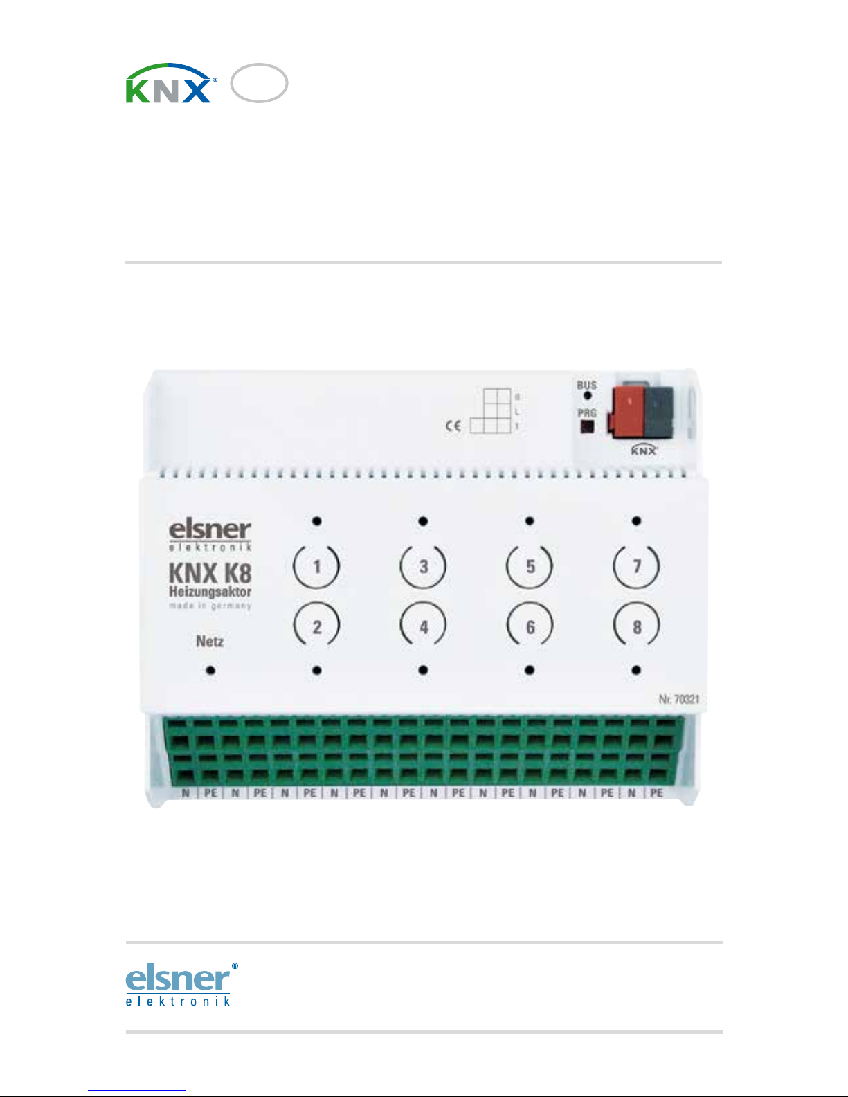
KNX K8
Actuator for Heating and Cooling
Item number 70321
Page 2

1 Contents
Elsner Elektronik GmbH • Sohlengrund 16 • 75395 Ostelsheim • Germany
KNX K8 actuator • from software version 1.00, ETS programme version 1.0
Status: 26.02.2016 • Subject to technical changes. Errors excepted.
1. Description ........................................................................................... 3
1.1. Technical data ........................................................................................................... 3
2. Installation and start-up ....................................................................... 4
2.1. Installation notes ...................................................................................................... 4
2.2. Device connection and design ................................................................................ 5
2.3. Notes on mounting and commissioning ................................................................ 5
2.3.1. Buttons and LEDs for the output channels ................................................. 5
3. Transmission protocol ......................................................................... 7
3.1. List of all communications objects ......................................................................... 7
4. Parameter setting .............................................................................. 10
4.1. Behaviour on power failure/ restoration of power .............................................. 10
4.2. General settings ..................................................................................................... 10
4.3. Channel 1...8 ........................................................................................................... 11
4.4. Temperature controller .......................................................................................... 13
4.4.1. General regulation ...................................................................................... 13
4.4.2. General set point values ............................................................................. 15
4.4.3. Heating control level 1/2 ............................................................................. 18
4.4.4. Cooling control level 1/2 ............................................................................. 20
Page 3
2 Clarification of signs
This manual is amended periodically and will be brought into line with new software
releases. The change status (software version and date) can be found in the contents footer.
If you have a device with a later software version, please check
www.elsner-elektronik.de in the menu area "Service" to find out whether a more up-todate version of the manual is available.
Clarification of signs used in this manual
Installation, inspection, commissioning and troubleshooting of the device
must only be carried out by a competent electrician.
Safety advice.
Safety advice for working on electrical connections, components,
etc.
DANGER!
... indicates an immediately hazardous situation which will lead to
death or severe injuries if it is not avoided.
WARNING!
... indicates a potentially hazardous situation which may lead to
death or severe injuries if it is not avoided.
CAUTION!
... indicates a potentially hazardous situation which may lead to
trivial or minor injuries if it is not avoided.
ATTENTION!
... indicates a situation which may lead to damage to property if it is
not avoided.
ETS In the ETS tables, the parameter default settings are marked by
underlining.
Page 4

3 Description
KNX K8 actuator • Version: 26.02.2016 • Technical Changes and Errors excepted.
1. Description
The KNX K8 actuator offers eight internal temperature regulators and eight output
channels for controlling heating or cooling systems. The temperature regulators can
control both the outputs on the KNX K8 and other climate control system on the KNXBus.
In automatic mode, the temperature regulators are set at nominal temperatures for
different modes. This way, it is easy to switch between the modes, comfort, standby,
eco and building protection. The switch is made via an object e. g. via a manual switch,
time switch or sensor switch outputs in the KNX-System.
The buttons on the device allow for direct manual switching of the connected systems.
LEDs show whether the output channel was manually operated or is running in an
automatic mode.
Functions:
• 8 internal, independent temperature regulators with automatic controls
for the heating and cooling controls (one or two step heating and cooling)
• 8 output channels (230 V AC, 8 Watt per output) with pulse width modulation
control (PWM) for actuators
• Keypad field 8 buttons and status LEDs
Configuration is made using the KNX software ETS. The product file can be
downloaded from the Elsner Elektronik homepage on www.elsner-elektronik.de in
the “Service” menu.
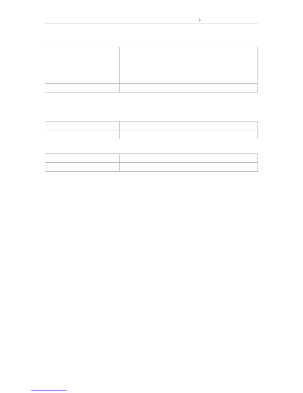
1.1. Technical data
Housing Plastic
Colour White
Mounting Series installation on mounting rail
Protection category IP 20
Dimensions
approx. 107 x 88 x 60 (W x H x D, mm), 6 modules
Weight approx. 270 g
Ambient temperature Operation -20…+70°C, storage -55…+90°C
Ambient humidity max. 95% RH, avoid condensation
Operating voltage 230V AC, 50 Hz
Power consumption max. 2 W
Power on bus: 10 mA
Outputs 8 x 230 V (OUT/N), not short-circuit-proof.
When connectiong one consumer load per separate channel
(1 to 8):
Max. load for continuous operation: 8 W per channel
Max. switch-on current: 1.1 A per channel
Observe the specifications in the data sheet of the consumer
load.
Data output KNX +/- bus connector terminal
Page 5

4 Installation and start-up
KNX K8 actuator • Version: 26.02.2016 • Technical Changes and Errors excepted.
The product conforms with the provisions of EU directives.
2. Installation and start-up
2.1. Installation notes
Installation, testing, operational start-up and troubleshooting should
only be performed by an electrician.
DANGER!
Risk to life from live voltage (mains voltage)!
There are unprotected live components within the device.
• VDE regulations and national regulations are to be followed.
• Ensure that all lines to be assembled are free of voltage and take
precautions against accidental switching on.
• Do not use the device if it is damaged.
• Take the device or system out of service and secure it against
unintentional use, if it can be assumed, that risk-free operation is no
longer guaranteed.
The device is only to be used for its intended purpose. Any improper modification or
failure to follow the operating instructions voids any and all warranty and guarantee
claims.
After unpacking the device, check it immediately for possible mechanical damage. If it
has been damaged in transport, inform the supplier immediately.
The device may only be used as a fixed-site installation; that means only when
assembled and after conclusion of all installation and operational start-up tasks and
only in the surroundings designated for it.
Elsner Elektronik is not liable for any changes in norms and standards which may occur
after publication of these operating instructions.
BCU type unit's own microcontroller
PEI type 0
Group addresses max. 254
Assignments max. 254
Communication objects 249
Page 6
5 Installation and start-up
KNX K8 actuator • Version: 26.02.2016 • Technical Changes and Errors excepted.
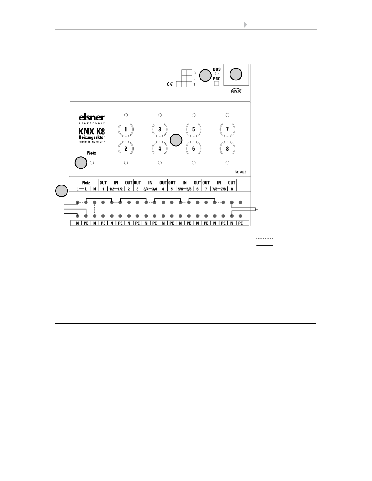
2.2. Device connection and design
2.3. Notes on mounting and commissioning
Device must not be exposed to water (rain). This could result in the electronics being
damaged. A relative air humidity of 95% must not be exceeded. Avoid condensation.
After the operating voltage has been applied, the device will enter an initialisation
phase lasting a few seconds. During this phase no information can be received or sent
via the bus.
2.3.1. Buttons and LEDs for the output channels
The buttons on the devices can be deactivated in the ETS (active when delivered).
1) Programming LED and programming buttons (PRG)
2) Bus terminal slot (KNX +/-)
3) Network LED (power)
4) Buttons and LEDs outputs 1-8
5) Sample connection: Per output max. 8 W
• Operating voltage input 230 V AC L/N/PE
L bridged to IN 1/2, IN 3/4, IN 5/6, IN 7/8
• Actuator on output 8 (OUT 8 | N)
All terminals N or PE of the lower connection strip are bridged internally.
3
4
5
1
2
Actuator
drive
L
PE
N
Internally
Series
installation on
mounting rail
(6 modules)
bridged cables
Page 7
6 Installation and start-up
KNX K8 actuator • Version: 26.02.2016 • Technical Changes and Errors excepted.
Buttons
LEDs
Behaviour of the LEDs for the output channels
in Automatic mode:
in Manual mode:
brief button press (<0,5 s) LED shows current status (see ETS parameter: Channel
LED)
button press >0,5 s in Automatic mode: Switching to Manual mode
in Manal mode: Switching from manually ON to
manually OFF and reverse
long button press (>3 s) Switching to Automatic mode (when activated in ETS)
Off Actuating variable = 0%
On Actuating variable > 0%
Flashes slowly Manually OFF
Flashes fast Manually ON
Page 8
7 Transmission protocol
KNX K8 actuator • Status: 18.11.13 • Technical Changes and Errors excepted.
3. Transmission protocol
Units:
Temperatures in degrees Celsius
Variables in %
3.1. List of all communications objects
Abbreviation flags:
C Communication
R Reading
WWriting
T Transferring
UUpdating
No. Name Function DPT Flags
0 Software version Output 217,001 C R T
1 Channel 1: Control / Status Input / Output 5,001 C R W T
2 Channel 1: Auto / Manual Input / Output 5.002 C R W T
3 Channel 1: Block Input 1.001 K S
4 Channel 2: Control / Status Input / Output 5,001 C R W T
5 Channel 2: Auto / Manual Input / Output 5.002 C R W T
6 Channel 2: Block Input 1.001 K S
7 Channel 3: Control / Status Input / Output 5,001 C R W T
8 Channel 3: Auto / Manual Input / Output 5.002 C R W T
9 Channel 3: Block Input 1.001 K S
10 Channel 4: Control / Status Input / Output 5,001 C R W T
11 Channel 4: Auto / Manual Input / Output 5.002 C R W T
12 Channel 4: Block Input 1.001 K S
13 Channel 5: Control / Status Input / Output 5,001 C R W T
14 Channel 5: Auto / Manual Input / Output 5.002 C R W T
15 Channel 5: Block Input 1.001 K S
16 Channel 6: Control / Status Input / Output 5,001 C R W T
17 Channel 6: Auto / Manual Input / Output 5.002 C R W T
18 Channel 6: Block Input 1.001 K S
19 Channel 7: Control / Status Input / Output 5,001 C R W T
20 Channel 7: Auto / Manual Input / Output 5.002 C R W T
21 Channel 7: Block Input 1.001 K S
Page 9

8 Transmission protocol
KNX K8 actuator • Status: 18.11.13 • Technical Changes and Errors excepted.
Temperature control (TC)
22 Channel 8: Control / Status Input / Output 5,001 C R W T
23 Channel 8: Auto / Manual Input / Output 5.002 C R W T
24 Channel 8: Block Input 1.001 K S
T
C
1
T
C
2
TC 3TC 4TC 5TC 6TC 7TC 8Name Func
tion
DPT Flags
25 53 81 109 137 165 193 221 TC_X_ measured
temperature
value
Input 9,001 K S
26 54 82 110 138 166 194 222 TC_X_ Eco-
Standby
HVAC 1
Input 1,003 K S
27 55 83 111 139 167 195 223 TC_X_ comfort
activation HVAC
2
Input 1,003 K S
28 56 84 112 140 168 196 224 TC_X_ Frost/heat
activation
Input 1,003 C R W
T
29 57 85 113 141 169 197 225 TC_X_ Blocking
object
Input 1.003 K S
30 58 86 114 142 170 198 226 RC_X_ Current
set point
Output9,001 C R T
31 59 87 115 143 171 199 227 TC_X_ Switching
object (0:Heating
| 1:Cooling)
Input 1,002 K S
32 60 88 116 144 172 200 228 TC_X_ Set point,
comfort heating
Input
/
Outp
ut
9,001 C R W
T
33 61 89 117 145 173 201 229 TC_X_ Set point,
comfort heating
(1:+ | 0:-)
Input 1.002 K S
34 62 90 118 146 174 202 230 TC_X_ Set point,
comfort cooling
Input
/
Outp
ut
9,001 C R W
T
35 63 91 119 147 175 203 231 TC_X_ Set point,
comfort cooling
(1:+ | 0:-)
Input 1.002 K S
36 64 92 120 148 176 204 232 TC_X_ Set point,
standby heating
Input
/
Outp
ut
9,001 C R W
T
No. Name Function DPT Flags
Page 10

9 Transmission protocol
KNX K8 actuator • Status: 18.11.13 • Technical Changes and Errors excepted.
37 65 93 121 149 177 205 233 TC_X_ Set point,
standby heating
(1:+ | 0:-)
Input 1.002 K S
38 66 94 122 150 178 206 234 TC_X_ Set point,
standby cooling
Input
/
Outp
ut
9,001 C R W
T
39 67 95 123 151 179 207 235 TC_X_ Set point,
standby cooling
(1:+ | 0:-)
Input 1.002 K S
40 68 96 124 152 180 208 236 TC_X_ Set point,
eco heating
Input
/
Outp
ut
9,001 C R W
T
41 69 97 125 153 181 209 237 TC_X_ Set point,
eco heating (1:+ |
0:-)
Input 1.002 K S
42 70 98 126 154 182 210 238 TC_X_ Set point,
eco cooling
Input
/
Outp
ut
9,001 C R W
T
43 71 99 127 155 183 211 239 TC_X_ Set point,
eco cooling (1:+ |
0:-)
Input 1.002 K S
44 72 100 128 156 184 212 240 TC_X_ Control
variable, heating
(level 1)
Output5,001 C R T
45 73 101 129 157 185 213 241 TC_X_ Control
variable, heating
(level 2)
Output5,001 C R T
46 74 102 130 158 186 214 242 TC_X_ Control
variable, cooling
(level 1)
Output5,001 C R T
47 75 103 131 158 187 215 243 TC_X_ Control
variable, cooling
(level 2)
Output5,001 C R T
48 76 104 132 160 188 216 244 TC_X_ Status
Heating 1 (1=ON
| 0=OFF)
Output1.002 C R T
49 77 105 133 161 189 217 245 TC_X_ Status
Heating 2 (1=ON
| 0=OFF)
Output1.002 C R T
T
C
1
T
C
2
TC 3TC 4TC 5TC 6TC 7TC 8Name Func
tion
DPT Flags
Page 11

10 Parameter setting
KNX K8 actuator • Status: 18.11.13 • Technical Changes and Errors excepted.
4. Parameter setting
4.1. Behaviour on power failure/ restoration of
power
Behaviour on bus or auxiliary power failure:
The device transmits nothing.
Behaviour on bus or auxiliary voltage restoration and following programming
or reset:
The device sends all outputs according to their transmission behaviour set in the
parameters with the delays established in the "General settings" parameter block. The
"Software version" communications object is sent once after 5 seconds.
4.2. General settings
The "power" LED shows readiness, i.e. whether an auxiliary voltage is used for the
device. Set the parameter to "no" if the LED is to remain off at all times.
Set basic characteristics of data transfer.
Select which channels and temperature controls you would like to use. The channels
control the connected heating/cooling systems on the output channels 1 to 8. Set the
50 78 106 134 162 190 218 246 TC_X_ Status
Cooling 1 (1=ON
| 0=OFF)
Output1.002 C R T
51 79 107 135 163 191 219 247 TC_X_ Status
Cooling 2 (1=ON
| 0=OFF)
Output1.002 C R T
52 80 108 136 164 192 220 248 TC_X_ Comfort
Delay status
Input
/
Outp
ut
1,002 C R W
T
Use standby LED Yes • No
Transmission delay after power-up and
programming
5 s • ... • 2 h
Maximum message rate • 1 message per second
• ...
• 0 messages per second
• ...
• 20 messages per second
T
C
1
T
C
2
TC 3TC 4TC 5TC 6TC 7TC 8Name Func
tion
DPT Flags
Page 12

11 Parameter setting
KNX K8 actuator • Status: 18.11.13 • Technical Changes and Errors excepted.
ambient climate automatic control in the temperature controls. The controls may be
used both for internal channels and for other heating/cooling actuators.
4.3. Channel 1...8
Use the channel menus to select the controls for the heating or cooling system
connected to the respective output channel.
First, select the type of valve, then the valve protection interval. This is the interval
after which the valve is opened and closed once to avoid jamming.
Select the control type for the valve:
When controls are effected via a 1 bit object, fixed output values are selected for
1 (On) and 0 (Off);
When controls are effected via a 8 bit object, fixed output values are selected for "not
0 (On) and 0(Off);
For controls via an 8 bit object with pulse width modulation (PWM), only the
basic time for the pulse width modulation is set (next setting).
If control takes place via one of the internal temperature controls, control and
variable are selected.
Use channel 1...8 Yes• No
Use temperature control 1...4 Yes• No
Valve type • normally closed
• normally open
Valve protection interval (days)
(0=deactivated)
0…255; 14
Control type • via object (1 bit)
• via object (8 bit ON | OFF)
• via object (8 bit PWM)
• via temperature controller
Value of output when object value = 1 0…100
Value of output when object value = 0 0…100
Output value
if object value is not 0
0…100
Output value
if object value is 0
0…100
Temperature controller no. 1 • 2 • 3 • 4
Page 13

12 Parameter setting
KNX K8 actuator • Status: 18.11.13 • Technical Changes and Errors excepted.
Please note that for a reset time of less than 5 minutes, the pulse with modulation may
only be modified in degrees of 5%.
For all control types, add the basis time for the valve pulse width modulation. The
basis time determines the signal duration for 100% open, i.e. a basic time of 100
seconds refers to a signal of 30 seconds (followed by 70 seconds without a signal) 30%
opening of the valve.
Select whether you want the control object to be monitored (not for controls via
internal temperature control)
Determine whether the output may also be controlled manually and configure the
manual function and automatic switches.
If manual control is disabled, the keys on the device are not activated. If manual
operation is activated, manual mode becomes active when a key is pressed on the
device or respective information is received via the "Channel X: Auto / Manual" object.
Actuating variable • Heating level 1
• Heating level 2
• Cooling level 1
• Cooling level 2
• Common level 1
• Common level 2
Valve PWM basis time in seconds 1…6000; 100
Use control object monitoring Yes • No
Monitoring time 5 s … 2 h; 10 min
Output value in case of
time out (in %)
0...100
Allow manual operation Yes• No
Object evaluation • Auto = 0 | Manual = 1
• Auto = 1 | Manual = 0
Object value prior to 1. communication 0 • 1
Output value when On (in %) 0…100
Output value when Off (in %) 0…100
Object "Auto / Manual" sends • not
• periodically
• on change
• on change and periodically
Transmit cycle
(for periodical transmission only)
5 s … 2 h; 10 s
Switching to Automatic mode is carried
out
• not
• after a period of time
• upon extended key actuation (> 3 s)
• upon extended button actuation or upon
time setting
Time
(only if switched to time)
5 s … 2 h; 1 min
Page 14

13 Parameter setting
KNX K8 actuator • Status: 18.11.13 • Technical Changes and Errors excepted.
Determine when the general channel status (e.g. ON, OFF, percentage) is to be sent.
The channel may be blocked by a blocking object (e. g. block during ventilation). The
output value during the block can be set.
The channel LED shows when the output channel is ON. When the channel is
switched on in automatic mode, the LED is on. When the channel is switched on in
manual mode, the LED flashes.
LED light or flashing may be switched off after a certain period to save energy.
4.4. Temperature controller
The KNX K8 actuator provides eight temperature controls that are independent of
the device outputs and thus may also be used for the control of other heating/cooling
actuators.
4.4.1. General regulation
For an adequate regulation of the indoor temperature, comfort, standby, eco and
building protection modes may be used.
Comfort when present,
Standby during short absences,
Eco as a night-time mode and
Frost/heat protection (building protection) during longer absences.
The settings for the temperature control include the set point temperatures for the
individual modes. Objects are used to determine which mode is to be selected. A
change of mode may be triggered manually or automatically (e.g. by a timer, window
contact).
Object "Control / Status" sends • not
• periodically
• on change
• on change and periodically
Transmit cycle
(for periodical transmission only)
5 s … 2 h; 10 s
Use block Yes• No
Output value when blocked (in %) 0…100
Object evaluation • 1 = block | 0 = release
• 0 = block | 1 = release
Object value prior to 1. communication 0 • 1
Channel LED • active when output ON
• active when output ON for certain period
Lighting time (in minutes) 1…60; 10
Page 15

14 Parameter setting
KNX K8 actuator • Status: 18.11.13 • Technical Changes and Errors excepted.
The mode may be switched with two 8 bit objects of different priority. Objects
"... HVAC mode (Prio 2)" for switching in everyday operation and
"... HVAC mode (Prio 1)" for central switching with higher priority.
The objects are coded as follows:
Alternatively, you can use three objects, with one object switching between eco and
standby mode and the two others are used to activate comfort mode or frost/heat
protection mode. The comfort object then blocks the eco/standby object, and frost/heat
protection objects have the highest priority. Objects
"... Mode (1: Eco, 0: Standby)",
"... comfort activation mode" and
"... frost/heat protection activation mode"
Select the mode to be activated after reset (e.g. power failure, reset of the line via the
bus). (Default).
Then configure a block of the temperature control by the blocking object.
Determine when the current settings of the controls are to be transmitted to the bus.
Periodic transmission is safer if a message does not reach a recipient. You may also
set up periodical monitoring by the actuator with this setting.
The status object shows the current status of the output variable (0 = OFF,
>0 = ON) and may, for example, be used for visualisations or to switch off the heating
pump as soon as the heating is off.
ID Name Encoding Range Use
20,102 DPT_HVACMode field1 = HVACMode
0 = Auto
1 = Comfort
2 = Standby
3 = Economy
4 = Building Protection
[0 … 4] HVAC
Switch mode via • two 8-bit objects (HVAC modes)
• three 1-bit objects
Mode after reset • Comfort
• Standby
• Eco
• Building protection
Behaviour of the blocking object at value • 1 = block | 0 = release
• 0 = block | 1 = release
Blocking object value
before 1st communication
0 • 1
Send actuating variables • on change
• on change and periodically
cycle
for periodical transmission only
5 s • ... • 5 min • … • 2 h
Page 16

15 Parameter setting
KNX K8 actuator • Status: 18.11.13 • Technical Changes and Errors excepted.
Then define the type of setting. Heating and/or cooling may be controlled in two levels.
4.4.2. General set point values
You may enter separate set point values for each mode or use the comfort set point as
a basic value.
If you are using the controls for both heating and cooling, you may also select the
setting "separately with switching object". Systems used for cooling in the summer
and for heating in the winter can thus be switched from one to the other.
If you are using the basic value, only the deviation from the comfort set point value is
listed for the other modes (e. g., 2°C less for standby mode).
The grades for the set point changes is predefined. Modifications may only remain
active temporarily (do not save) or remain saved even after voltage recovery (and
programming). This also applies to a comfort extension.
Send status objects • on change
• on change to 1
• on change to 0
• on change and periodically
• on change to 1 and periodically
• on change to 0 and periodically
cycle
for periodical transmission only
5 s • ... • 5 min • … • 2 h
Type of control • One-stage heating
• Dual-speed heating
• Single-speed cooling
• Dual-stage cooling
• Single-speed heating + Single-speed
cooling
• Dual-speed heating + Single-speed
cooling
• Dual-speed heating + Dual-speed cooling
Setting the nominal values • separate with switching object
• separate without switching object
• with comfort set point as a basis
Behaviour of the switching object at value
only if switching object is used
• 0 = Heating | 1 = Cooling
• 1 = Heating | 0 = Cooling
Switching object value
before 1st communication
only if switching object is used
0 • 1
Grading for set point changes
(in 0.1 °C)
1… 50; 10
Page 17

16 Parameter setting
KNX K8 actuator • Status: 18.11.13 • Technical Changes and Errors excepted.
The control may be manually reset to comfort mode from eco, or night mode. This
allows the user to maintain the daily nominal value for a longer time, e.g. when having
guests. The duration of this comfort extension period is set. After the comfort
extension period is terminated, the system returns to eco mode.
Set point Comfort
Comfort mode is usually used for daytime mode when people are present. A starting
value is defined for the comfort set point as well as a temperature range in which the
nominal value may be modified.
If the comfort set point is used as the basis, a dead zone is determined for the control
mode "heating and cooling" to avoid direct switching from heating to cooling.
Set point for standby
Standby mode is usually used for daytime mode when people are absent.
If set point values are entered separately:
A starting set point value is defined as well as a temperature range in which the
nominal value may be modified.
Saving set point value(s) and comfort
extension time
• not
• after voltage recovery
• after voltage recovery and
programming (do not use
for first start-up!)
Comfort extension time in seconds
(can only be activated from eco mode)
1…36000; 3600
Initial heating/cooling set point (in 0.1 °C)
valid till 1st communication
not upon saving the set point value after
programming
-300…800; 210
Min. object value heating/cooling (in 0.1
°C)
-300…800; 160
Max. object value heating/cooling (in 0.1
°C)
-300…800; 280
Dead zone between heating and cooling
only if both heating AND cooling are used.
1…100; 50
Initial heating/cooling set point (in 0.1 °C)
valid till 1st communication
-300…800; 210
Min. object value heating/cooling (in 0.1
°C)
-300…800; 160
Max. object value heating/cooling (in 0.1
°C)
-300…800; 280
Page 18

17 Parameter setting
KNX K8 actuator • Status: 18.11.13 • Technical Changes and Errors excepted.
If the comfort set point value is used as a basis:
If the comfort set point value is used as a basis, the deviation from this value is set.
Eco set point
Eco mode is usually used for night mode.
If set point values are entered separately:
A starting set point value is defined as well as a temperature range in which the
nominal value may be modified.
If the comfort set point value is used as a basis:
If the comfort set point value is used as a basis, the deviation from this value is set.
Set point values for frost/heat protection (building protection)
The building protection mode is used during longer absences. Set points for frost
protection (heating) and heat protection (cooling) are determined which may not be
modified from outside (no access via operating devices etc.). The building protection
mode may be activated with delay, which allows you to leave the building before the
controls switch to frost/heat protection mode.
General variables
This setting appears for the control types "Heating and Cooling" only. This is where
you can decide whether to use a common variable for heating and cooling. If the 2nd
level has a common variable, this is also where you determine the control mode of the
2nd level.
Reduce nominal heating value (in 0.1°C)
for heating
0…200; 30
Increase nominal cooling value\r\n (in
0.1°C)
for cooling
0…200; 30
Initial heating/cooling set point (in 0.1 °C)
valid till 1st communication
-300…800; 210
Min. object value heating/cooling (in 0.1
°C)
-300…800; 160
Max. object value heating/cooling (in 0.1
°C)
-300…800; 280
Reduce nominal heating value (in 0.1°C)
for heating
0…200; 50
Increase nominal cooling value\r\n (in
0.1°C)
for cooling
0…200; 60
Nominal value frost protection\r\n (in 0,1°C) -300…800; 70
Nominal value heat protection (in 0,1°C) -300…800; 350
Activation delay no • 5 s • ... • 5 min • … • 2 h
Page 19

18 Parameter setting
KNX K8 actuator • Status: 18.11.13 • Technical Changes and Errors excepted.
4.4.3. Heating control level 1/2
If a heating control mode is configured, one or two setting sections for the heating
levels are displayed.
On the 1st level, heating is controlled by a PI control which allows to either enter
control parameters or select predetermined applications.
On the 2nd level (therefore only in case of a 2 level heating), heating is controlled via
a PI or a 2-point-control.
On level 2, the set point deviation between the two levels must furthermore be
determined, i. e. the lowest set point value from which the 2nd level is then added
(when values exceed this set point).
PI control with control parameters:
This setting allows individual input of the parameters for PI control.
Determine the deviation from the set point value which reaches maximum variable
value, i. e. the point at which maximum heating power is activated.
The reset time shows how quickly the controls react to deviations from the set point
value. In case of a short reset time, the controls react with a fast increase of the
For heating and cooling • separate variables are used
• common variables are used for
Level 1
• common variables are used for
Level 2
• common variables are used for
Level 1+2
Control type
only for level 2
• 2-point control
• PI control
Regulating variable of the 2nd Stage is on
only for level 2
• 1-bit object
• 8-bit object
Set point difference between levels 1 and 2
(in 0.1°C)
only for level 2
0…100; 40
Control type
only for level 2 and if no common variables
are used
• 2-point control
• PI control
Control type • PI control
Set control using • Controller parameter
• provided applications
Page 20

19 Parameter setting
KNX K8 actuator • Status: 18.11.13 • Technical Changes and Errors excepted.
variable. In case of a long reset time, the controls react somewhat more gently and
needs longer until the necessary variable for the set point deviation is reached.
You should set the time appropriate to the heating system at this point (note
manufacturer instructions).
Now determine what should be transmitted when the control is blocked. Set a value
greater 0 (=OFF) to receive a basic heating level, e.g. for floor heating.
Upon release, the control variable follows the rule again.
In case of a common variable for heating and cooling, 0 is always transmitted as a fixed
value.
PI control with predetermined application:
This setting provides fixed parameters for frequent applications.
Now determine what should be transmitted when the control is blocked. Set a value
greater 0 (=OFF) to receive a basic heating level, e.g. for floor heating.
Upon release, the control variable follows the rule again.
In case of a common variable for heating and cooling, 0 is always transmitted as a fixed
value.
Maximum control variable is reached
at set point/actual difference of (in °C)
0...5
Reset time (in min.) 1…255; 30
When blocked, the variable shall • not be transmitted
• send a specific value
Value (in %)
only if a value is transmitted
0...100
Control type • PI control
Set control using • Controller parameter
• provided applications
Application • Warm water heating
• Floor heating
• Convection unit
• Electric heating
Maximum control variable is reached
at set point/actual difference of (in °C)
Warm water heating: 5
Floor heating: 5
Convection unit: 4
Electric heating: 4
Reset time (in min.) Warm water heating: 150
Floor heating: 240
Convection unit: 90
Electric heating: 100
When blocked, the variable shall • not be transmitted
• send a specific value
Value (in %)
only if a value is transmitted
0...100
Page 21

20 Parameter setting
KNX K8 actuator • Status: 18.11.13 • Technical Changes and Errors excepted.
2-point-rule (only level 2):
The 2-point-rule is used for systems which are only set to ON or OFF.
Enter the hysteresis that prevents frequent on/off switching of temperatures in the
threshold range. Then determine whether a 1 bit object (on/off) or an 8 bit object (on
with percentage/off) should be used.
Now determine what should be transmitted when the control is blocked. Set a value
greater 0 (=OFF) to receive a basic heating level, e.g. for floor heating.
Upon release, the control variable follows the rule again.
4.4.4. Cooling control level 1/2
If a cooling control mode is configured, one or two setting sections for the cooling
levels are displayed.
On the 1st level, cooling is controlled by a PI control which allows to either enter
control parameters or select predetermined applications.
On the 2nd level (therefore only in case of a 2 level cooling), cooling is controlled via a
PI or a 2-point-control.
On level 2, the set point deviation between the two levels must furthermore be
determined, i. e. the highest set point value from which the 2nd level is then added
(when values exceed this set point).
PI control with control parameters:
This setting allows individual input of the parameters for PI control.
Control type
is determined at a higher level for common
variables
• 2-point control
Hysteresis (in 0.1°C) 0…100; 20
Actuating variable is a • 1-bit object
• 8-bit object
Value (in %)
only for 8 bit objects
0...100
When blocked, the variable shall • not be transmitted
• send a specific value
Value (in %)
only if a value is transmitted
0...100
Set point difference between levels 1 and 2
(in 0.1°C)
only for level 2
0…100; 40
Control type
only for level 2 and if no common variables
are used
• 2-point control
• PI control
Control type • PI control
Page 22

21 Parameter setting
KNX K8 actuator • Status: 18.11.13 • Technical Changes and Errors excepted.
Determine the deviation from the set point value which reaches maximum variable
value, i. e. the point at which maximum cooling power is activated.
The reset time shows how quickly the controls react to deviations from the set point
value. In case of a short reset time, the controls react with a fast increase of the
variable. In case of a long reset time, the controls react somewhat more gently and
needs longer until the necessary variable for the set point deviation is reached.
You should set the time appropriate to the cooling system at this point (note
manufacturer instructions).
Now determine what should be transmitted when the control is blocked.
Upon release, the control variable follows the rule again.
In case of a common variable for heating and cooling, 0 is always transmitted as a fixed
value.
PI control with predetermined application:
This setting provides fixed parameters for a cooling ceiling
Now determine what should be transmitted when the control is blocked.
Upon release, the control variable follows the rule again.
2-point-rule (only level 2):
The 2-point-rule is used for systems which are only set to ON or OFF.
Set control using • Controller parameter
• provided applications
Maximum control variable is reached
at set point/actual difference of (in °C)
0...5
Reset time (in min.) 1…255; 30
When blocked, the variable shall • not be transmitted
• send a specific value
Value (in %)
only if a value is transmitted
0...100
Control type • PI control
Set control using • Controller parameter
• provided applications
Application • Cooling ceiling
Maximum control variable is reached
at set point/actual difference of (in °C)
Cooling ceiling: 5
Reset time (in min.) Cooling ceiling: 30
When blocked, the variable shall • not be transmitted
• send a specific value
Value (in %)
only if a value is transmitted
0...100
Page 23

22 Parameter setting
KNX K8 actuator • Status: 18.11.13 • Technical Changes and Errors excepted.
Enter the hysteresis that prevents frequent on/off switching of temperatures in the
threshold range. Then determine whether a 1 bit object (on/off) or an 8 bit object (on
with percentage/off) should be used.
Now determine what should be transmitted when the control is blocked.
Upon release, the control variable follows the rule again.
In case of a common variable for heating and cooling, 0 is always transmitted as a fixed
value.
Control type
is determined at a higher level for common
variables
• 2-point control
Hysteresis (in 0.1°C) 0…100; 20
Actuating variable is a • 1-bit object
• 8-bit object
Value (in %)
only for 8 bit objects
0...100
When blocked, the variable shall • not be transmitted
• send a specific value
Value (in %)
only if a value is transmitted
0...100
Page 24

Elsner Elektronik GmbH Control and Automation Technology
Sohlengrund 16
75395 Ostelsheim Phone +49(0)70 33 / 30945-0 info@elsner-elektronik.de
Germany Fax +49(0)70 33 / 30945-20 www.elsner-elektronik.de
Technical support: +49 (0) 70 33 / 30 945-250
 Loading...