

Page 1
EN
KNX Interface
For Building Control System WS1000 Color
or WS1000 Style
Item number 70190
Installation and Adjustment
Page 2

1 Contents
1. Description ........................................................................................... 3
1.1. Scope of delivery ...................................................................................................... 3
1.2. Technical specifications ........................................................................................... 3
2. Installation and commissioning ........................................................... 4
2.1. Installation notes ...................................................................................................... 4
2.2. Mounting and connection ....................................................................................... 4
2.2.1. Fitting the interface to the board of WS1000 .............................................. 5
2.2.2. Connection .................................................................................................... 5
3. Procedure ............................................................................................. 6
4. KNX transmission protocol .................................................................. 7
4.0.1. Abbreviations ................................................................................................ 7
4.1. List of all communications objects ......................................................................... 7
5. Parameter setting .............................................................................. 24
5.0.1. Malfunctions and error messages ............................................................. 24
5.1. General settings ..................................................................................................... 24
5.2. Wind sensors .......................................................................................................... 25
5.3. Weather data .......................................................................................................... 26
5.3.1. Weather data is transmitted on the bus .................................................... 26
5.3.2. Weather data is received from the bus ..................................................... 28
5.4. Functional blocks .................................................................................................... 29
5.4.1. Blocks with 7 objects .................................................................................. 29
5.4.2. Blocks with 3 objects .................................................................................. 30
5.4.3. Blocks with 2 objects .................................................................................. 30
5.4.4. Blocks with 1 object .................................................................................... 31
Elsner Elektronik GmbH • Sohlengrund 16 • 75395 Ostelsheim • Germany
KNX Interface for WS1000 • from WS1000 software version 1.8, ETS programm version 3.0
Status: 15.04.2016 • Subject to technical changes. Errors excepted.
Page 3
2 Clarification of signs
Installation, inspection, commissioning and troubleshooting of the device
must only be carried out by a competent electrician.
This manual is amended periodically and will be brought into line with new software
releases. The change status (software version and date) can be found in the contents footer.
If you have a device with a later software version, please check
www.elsner-elektronik.de in the menu area "Service" to find out whether a more up-todate version of the manual is available.
Clarification of signs used in this manual
Safety advice.
Safety advice for working on electrical connections, components,
etc.
DANGER!
WARNING!
CAUTION!
ATTENTION!
ETS In the ETS tables, the parameter default settings are marked by
... indicates an immediately hazardous situation which will lead to
death or severe injuries if it is not avoided.
... indicates a potentially hazardous situation which may lead to
death or severe injuries if it is not avoided.
... indicates a potentially hazardous situation which may lead to
trivial or minor injuries if it is not avoided.
... indicates a situation which may lead to damage to property if it is
not avoided.
underlining.
Page 4

3 Description
1. Description
The KNX Interface for WS1000 allows for communication between the WS1000
Color or WS1000 Style Control System and the KNX bus system. On the one hand, data
of the control unit can be sent to the KNX bus (e. g. weather data). On the other hand,
the WS1000 can control drives in the KNX system directly and use sensor data from
the KNX system.
Functions:
• Transmission of data from WS1000 Color/Style to the KNX bus: date/
time, position, weather data
• Control of actuators in the KNX bus system by the automatic functions of the
WS1000 Color/Style: awnings, blinds, roller shutters, windows, light
• Transmission of bus data to the WS1000 Color/Style: sensor data, push-
button commands
Configuration is made using the KNX software ETS. The product file can be downloaded from the Elsner Elektronik homepage on www.elsner-elektronik.de in the
“Service” menu.
1.1. Scope of delivery
•Interface
• KNX bus connector terminal
Interface and bus connector terminal are plugged on the board of the Control System
WS1000 Color/WS1000 Style.
1.2. Technical specifications
Mounting is plugged on the board of the Control WS1000
Dimensions approx. 53 × 7 × 30 (W × H × D, mm)
Weight approx. 10 g
Ambient temperature operation 0…+50°C, storage -30…+70°C,
Operating voltage KNX bus voltage
Bus current max. 5,5 mA,
Data output KNX +/- bus connector terminal
BCU type own micro controller
PEI type 0
Group addresses max. 254
Assingnments max. 254
Communication objects 254
The product conforms with the provisions of EU directives.
KNX Interface for WS1000 • Status: 15.04.2016 • Technical changes reserved. Errors reserved.
avoid bedewing
max. 9 mA when programming LED is active
Page 5

4 Installation and commissioning
2. Installation and commissioning
2.1. Installation notes
Installation, testing, operational start-up and troubleshooting should
only be performed by an electrician.
DANGER!
Risk to life from live voltage (mains voltage)!
There are unprotected live components within the device.
• VDE regulations and national regulations are to be followed.
• Ensure that all lines to be assembled are free of voltage and take
precautions against accidental switching on.
• Do not use the device if it is damaged.
• Take the device or system out of service and secure it against
unintentional use, if it can be assumed, that risk-free operation is no
longer guaranteed.
The device is only to be used for its intended purpose. Any improper modification or
failure to follow the operating instructions voids any and all warranty and guarantee
claims.
After unpacking the device, check it immediately for possible mechanical damage. If it
has been damaged in transport, inform the supplier immediately.
The device may only be used as a fixed-site installation; that means only when assembled and after conclusion of all installation and operational start-up tasks and only in
the surroundings designated for it.
Elsner Elektronik is not liable for any changes in norms and standards which may occur
after publication of these operating instructions.
2.2. Mounting and connection
Please take note of the chapters about installation of the control unit WS1000 in the
manual of WS1000 Color/Style.
KNX Interface for WS1000 • Status: 15.04.2016 • Technical changes reserved. Errors reserved.
Page 6
5 Installation and commissioning
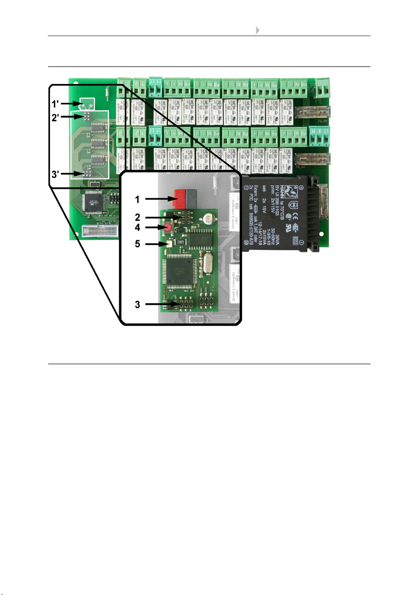
1‘ Slot KNX terminal +/2‘/3‘Pins for connection of inter-
face
1 KNX terminal plug +/2/3 Plug sockets
4 Programming button for
setting up the device
5 Programming LED
2.2.1. Fitting the interface to the board of WS1000
2.2.2. Connection
The KNX Interface for WS1000 is plugged on the connection board of the WS1000
Color or WS1000 Style. There are 2 blocks with 6 pins each for this purpose (no. 2’ and
3’). Place the interface on the pins and push it down.
Connect the KNX bus cable to the bus connector (red/black) and plug the connector to
the slot of the WS1000 board (no. 1’).
Before closing the housing of the control again, set up the bus connection with the programming button (no. 4). The KNX interface is displayed in the starting sequence of the
control (KNX interface found).
KNX Interface for WS1000 • Status: 15.04.2016 • Technical changes reserved. Errors reserved.
Page 7

6
2.3. Procedure
After the professional installation and commissioning, the basic settings have to be
made in the ETS and then in the control menu System > Installation.
After the programming in the ETS, the control must be reset (also when making
changes).
6.3.2. Service-Einstellungen, Reset
System > WS1000 einstellen > Service > Reset
Control System KNX WS1000 Color • Status: 15.04.2016 • Errors excepted. Subject to technical changes.
Page 8

7
2.4. KNX transmission protocol
Abbreviations
Flags:
C: Communication
R: Read
W: Write
T: Transfer
AU: Update
2.4.1. List of all communications objects
No. Name Function DPT Flags
0 Software version Output 217,001 C R T
1 Date Input / Output 11,001 C W T
2 Time Input / Output 10,001 C W T
3 Date and time request Input 1,017 C S
4 Location Breitengrad Output 14,007 C R T
5 Location Laengengrad Output 14,007 C R T
6 Sun elevation Azimuth Output 14,007 C R T
7 Sun position Elevation Output 14,007 C R T
8 Sun elevation Azimuth Output 9.* C R T
9 Sun position Elevation Output 9.* C R T
10 Switching output night Output 1,002 C R T
11 Switching output rain Input / Output 1,002 C R W T
12 Outdoor temperature
measurement value
13 Wind force measurement value Input / Output 9,005 C R W T
14 Wind force sensor 1 measurement
value
15 Wind force sensor 2 measurement
value
16 Wind force sensor 3 measurement
value
17 Wind force sensor 4 measurement
value
18 Wind direction 2 Byte Input 9.* C W
19 Winddirection 4 Byte Input 14.007 C W
20 Brightness measurement value Input / Output 9,004 C R W T
21 Reserve
22 WS1000 defect Output 1,002 C R T
23 Wind sensor defect Output 1,002 C R T
Input / Output 9,001 C R W T
Input 9.005 C W
Input 9.005 C W
Input 9.005 C W
Input 14.007 C R W T
KNX Interface for WS1000 • Status: 15.04.2016 • Errors excepted. Subject to technical changes.
Page 9

8
No. Name Function DPT Flags
24 Temperature sensor defect Output 1,002 C R T
25 Weather station defect Output 1,002 C R T
26 Block Input 1,002 C S
27 Wind sensor 1 defect Output 1.002 C R T
28 Wind sensor 2 defect Output 1.002 C R T
29 Wind sensor 3 defect Output 1.002 C R T
30 Wind sensor 4 defect Output 1.002 C R T
31 Wind direction defect Output 1.002 C R T
32 Reserve
33 Block 7_1: Long-time Input / Output 1,008 C W T
34 Block 7_1: Short-time Input / Output 1,01 C W T
35 Block 7_1: Actuation position Output 5,001 C T
36 Block 7_1: Slat position Output 5,001 C T
37 Block 7_1: Movement position
Input 5,001 C W T
feedback
38 Block 7_1: Slat position feedback Input 5,001 C W T
39 Block 7_1: Safety Output 1,002 C R T
33 Block 7_1: Switching Input / Output 1,001 C W T
34 Block 7_1: Switching feedback Output 1,001 C R T
34 Block 7_1: Dimming Output 3,007 C T
35 Block 7_1: Dimmer value in % Input / Output 5,001 C W T
37 Block 7_1: Temperature Input 9,001 C W T
38 Block 7_1: Air humidity Input 9,007 C W T
39 Block 7_1: CO2 Input 9,008 C W T
39 Block 7_1: 2 byte floating point Input 9.* C W T
39 Block 7_1: 4 byte floating point Input 14.* C W T
40 Block 7_2: Long-time Input / Output 1,008 C W T
41 Block 7_2: Short-time Input / Output 1,01 C W T
42 Block 7_2: Actuation position Output 5,001 C T
43 Block 7_2: Slat position Output 5,001 C T
44 Block 7_2: Movement position
Input 5,001 C W T
feedback
45 Block 7_2: Slat position feedback Input 5,001 C W T
46 Block 7_2: Safety Output 1,002 C R T
40 Block 7_2: Switching Output 1,001 C W T
41 Block 7_2: Switching feedback Input 1,001 C R T
41 Block 7_2: Dimming Output 3,007 C T
42 Block 7_2: Dimmer value in % Input / Output 5,001 C W T
44 Block 7_2: Temperature Input 9,001 C W T
KNX Interface for WS1000 • Status: 15.04.2016 • Errors excepted. Subject to technical changes.
Page 10

9
No. Name Function DPT Flags
45 Block 7_2: Air humidity Input 9,007 C W T
46 Block 7_2: CO2 Input 9,008 C W T
46 Block 7_2: 2 byte floating point Input 9.* C W T
46 Block 7_2: 4 byte floating point Input 14.* C W T
47 Block 7_3: Long-time Input / Output 1,008 C W T
48 Block 7_3: Short-time Input / Output 1,01 C W T
49 Block 7_3: Actuation position Output 5,001 C T
50 Block 7_3: Slat position Output 5,001 C T
51 Block 7_3: Movement position
Input 5,001 C W T
feedback
52 Block 7_3: Slat position feedback Input 5,001 C W T
53 Block 7_3: Safety Output 1,002 C R T
47 Block 7_3: Switching Output 1,001 C W T
48 Block 7_3: Switching feedback Input 1,001 C R T
48 Block 7_3: Dimming Output 3,007 C T
49 Block 7_3: Dimmer value in % Input / Output 5,001 C W T
51 Block 7_3: Temperature Input 9,001 C W T
52 Block 7_3: Air humidity Input 9,007 C W T
53 Block 7_3: CO2 Input 9,008 C W T
53 Block 7_3: 2 byte floating point Input 9.* C W T
53 Block 7_3: 4 byte floating point Input 14.* C W T
54 Block 7_4: Long-time Input / Output 1,008 C W T
55 Block 7_4: Short-time Input / Output 1,01 C W T
56 Block 7_4: Actuation position Output 5,001 C T
57 Block 7_4: Slat position Output 5,001 C T
58 Block 7_4: Movement position
Input 5,001 C W T
feedback
59 Block 7_4: Slat position feedback Input 5,001 C W T
60 Block 7_4: Safety Output 1,002 C R T
54 Block 7_4: Switching Output 1,001 C W T
55 Block 7_4: Switching feedback Input 1,001 C R T
55 Block 7_4: Dimming Output 3,007 C T
56 Block 7_4: Dimmer value in % Input / Output 5,001 C W T
58 Block 7_4: Temperature Input 9,001 C W T
59 Block 7_4: Air humidity Input 9,007 C W T
60 Block 7_4: CO2 Input 9,008 C W T
60 Block 7_4: 2 byte floating point Input 9.* C W T
60 Block 7_4: 4 byte floating point Input 14.* C W T
KNX Interface for WS1000 • Status: 15.04.2016 • Errors excepted. Subject to technical changes.
Page 11

10
No. Name Function DPT Flags
61 Block 7_5: Long-time Input / Output 1,008 C W T
62 Block 7_5: Short-time Input / Output 1,01 C W T
63 Block 7_5: Actuation position Output 5,001 C T
64 Block 7_5: Slat position Output 5,001 C T
65 Block 7_5: Movement position
Input 5,001 C W T
feedback
66 Block 7_5: Slat position feedback Input 5,001 C W T
67 Block 7_5: Safety Output 1,002 C R T
61 Block 7_5: Switching Output 1,001 C W T
62 Block 7_5: Switching feedback Input 1,001 C R T
62 Block 7_5: Dimming Output 3,007 C T
63 Block 7_5: Dimmer value in % Input / Output 5,001 C W T
65 Block 7_5: Temperature Input 9,001 C W T
66 Block 7_5: Air humidity Input 9,007 C W T
67 Block 7_5: CO2 Input 9,008 C W T
67 Block 7_5: 2 byte floating point Input 9.* C W T
67 Block 7_5: 4 byte floating point Input 14.* C W T
68 Block 7_6: Long-time Input / Output 1,008 C W T
69 Block 7_6: Short-time Input / Output 1,01 C W T
70 Block 7_6: Actuation position Output 5,001 C T
71 Block 7_6: Slat position Output 5,001 C T
72 Block 7_6: Movement position
Input 5,001 C W T
feedback
73 Block 7_6: Slat position feedback Input 5,001 C W T
74 Block 7_6: Safety Output 1,002 C R T
68 Block 7_6: Switching Output 1,001 C W T
69 Block 7_6: Switching feedback Input 1,001 C R T
69 Block 7_6: Dimming Output 3,007 C T
70 Block 7_6: Dimmer value in % Input / Output 5,001 C W T
72 Block 7_6: Temperature Input 9,001 C W T
73 Block 7_6: Air humidity Input 9,007 C W T
74 Block 7_6: CO2 Input 9,008 C W T
74 Block 7_6: 2 byte floating point Input 9.* C W T
74 Block 7_6: 4 byte floating point Input 14.* C W T
75 Block 7_7: Long-time Input / Output 1,008 C W T
76 Block 7_7: Short-time Input / Output 1,01 C W T
77 Block 7_7: Actuation position Output 5,001 C T
78 Block 7_7: Slat position Output 5,001 C T
KNX Interface for WS1000 • Status: 15.04.2016 • Errors excepted. Subject to technical changes.
Page 12

11
No. Name Function DPT Flags
79 Block 7_7: Movement position
Input 5,001 C W T
feedback
80 Block 7_7: Slat position feedback Input 5,001 C W T
81 Block 7_7: Safety Output 1,002 C R T
75 Block 7_7: Switching Output 1,001 C W T
76 Block 7_7: Switching feedback Input 1,001 C R T
76 Block 7_7: Dimming Output 3,007 C T
77 Block 7_7: Dimmer value in % Input / Output 5,001 C W T
79 Block 7_7: Temperature Input 9,001 C W T
80 Block 7_7: Air humidity Input 9,007 C W T
81 Block 7_7: CO2 Input 9,008 C W T
81 Block 7_7: 2 byte floating point Input 9.* C W T
81 Block 7_7: 4 byte floating point Input 14.* C W T
82 Block 7_8: Long-time Input / Output 1,008 C W T
83 Block 7_8: Short-time Input / Output 1,01 C W T
84 Block 7_8: Actuation position Output 5,001 C T
85 Block 7_8: Slat position Output 5,001 C T
86 Block 7_8: Movement position
Input 5,001 C W T
feedback
87 Block 7_8: Slat position feedback Input 5,001 C W T
88 Block 7_8: Safety Output 1,002 C R T
82 Block 7_8: Switching Output 1,001 C W T
83 Block 7_8: Switching feedback Input 1,001 C R T
83 Block 7_8: Dimming Output 3,007 C T
84 Block 7_8: Dimmer value in % Input / Output 5,001 C W T
86 Block 7_8: Temperature Input 9,001 C W T
87 Block 7_8: Air humidity Input 9,007 C W T
88 Block 7_8: CO2 Input 9,008 C W T
88 Block 7_8: 2 byte floating point Input 9.* C W T
88 Block 7_8: 4 byte floating point Input 14.* C W T
89 Block 7_9: Long-time Input / Output 1,008 C W T
90 Block 7_9: Short-time Input / Output 1,01 C W T
91 Block 7_9: Actuation position Output 5,001 C T
92 Block 7_9: Slat position Output 5,001 C T
93 Block 7_9: Movement position
Input 5,001 C W T
feedback
94 Block 7_9: Slat position feedback Input 5,001 C W T
95 Block 7_9: Safety Output 1,002 C R T
89 Block 7_9: Switching Output 1,001 C W T
KNX Interface for WS1000 • Status: 15.04.2016 • Errors excepted. Subject to technical changes.
Page 13

12
No. Name Function DPT Flags
90 Block 7_9: Switching feedback Input 1,001 C R T
90 Block 7_9: Dimming Output 3,007 C T
91 Block 7_9: Dimmer value in % Input / Output 5,001 C W T
93 Block 7_9: Temperature Input 9,001 C W T
94 Block 7_9: Air humidity Input 9,007 C W T
95 Block 7_9: CO2 Input 9,008 C W T
95 Block 7_9: 2 byte floating point Input 9.* C W T
95 Block 7_9: 4 byte floating point Input 14.* C W T
96 Block 7_10: Long-time Input / Output 1,008 C W T
97 Block 7_10: Short-time Input / Output 1,01 C W T
98 Block 7_10: Actuation position Output 5,001 C T
99 Block 7_10: Slat position Output 5,001 C T
100 Block 7_10: Movement position
Input 5,001 C W T
feedback
101 Block 7_10: Slat position feedback Input 5,001 C W T
102 Block 7_10: Safety Output 1,002 C R T
96 Block 7_10: Switching Output 1,001 C W T
97 Block 7_10: Switching feedback Input 1,001 C R T
97 Block 7_10: Dimming Output 3,007 C T
98 Block 7_10: Dimmer value in % Input / Output 5,001 C W T
100 Block 7_10: Temperature Input 9,001 C W T
101 Block 7_10: Air humidity Input 9,007 C W T
102 Block 7_10: CO2 Input 9,008 C W T
102 Block 7_10: 2 byte floating point Input 9.* C W T
102 Block 7_10: 4 byte floating point Input 14.* C W T
103 Block 7_11: Long-time Input / Output 1,008 C W T
104 Block 7_11: Short-time Input / Output 1,01 C W T
105 Block 7_11: Actuation position Output 5,001 C T
106 Block 7_11: Slat position Output 5,001 C T
107 Block 7_11: Movement position
Input 5,001 C W T
feedback
108 Block 7_11: Slat position feedback Input 5,001 C W T
109 Block 7_11: Safety Output 1,002 C R T
103 Block 7_11: Switching Output 1,001 C W T
104 Block 7_11: Switching feedback Input 1,001 C R T
104 Block 7_11: Dimming Output 3,007 C T
105 Block 7_11: Dimmer value in % Input / Output 5,001 C W T
107 Block 7_11: Temperature Input 9,001 C W T
108 Block 7_11: Air humidity Input 9,007 C W T
KNX Interface for WS1000 • Status: 15.04.2016 • Errors excepted. Subject to technical changes.
Page 14

13
No. Name Function DPT Flags
109 Block 7_11: CO2 Input 9,008 C W T
109 Block 7_11: 2 byte floating point Input 9.* C W T
109 Block 7_11: 4 byte floating point Input 14.* C W T
110 Block 7_12: Long-time Input / Output 1,008 C W T
111 Block 7_12: Short-time Input / Output 1,01 C W T
112 Block 7_12: Actuation position Output 5,001 C T
113 Block 7_12: Slat position Output 5,001 C T
114 Block 7_12: Movement position
Input 5,001 C W T
feedback
115 Block 7_12: Slat position feedback Input 5,001 C W T
116 Block 7_12: Safety Output 1,002 C R T
110 Block 7_12: Switching Output 1,001 C W T
111 Block 7_12: Switching feedback Input 1,001 C R T
111 Block 7_12: Dimming Output 3,007 C T
112 Block 7_12: Dimmer value in % Input / Output 5,001 C W T
114 Block 7_12: Temperature Input 9,001 C W T
115 Block 7_12: Air humidity Input 9,007 C W T
116 Block 7_12: CO2 Input 9,008 C W T
116 Block 7_12: 2 byte floating point Input 9.* C W T
116 Block 7_12: 4 byte floating point Input 14.* C W T
117 Block 7_13: Long-time Input / Output 1,008 C W T
118 Block 7_13: Short-time Input / Output 1,01 C W T
119 Block 7_13: Actuation position Output 5,001 C T
120 Block 7_13: Slat position Output 5,001 C T
121 Block 7_13: Movement position
Input 5,001 C W T
feedback
122 Block 7_13: Slat position feedback Input 5,001 C W T
123 Block 7_13: Safety Output 1,002 C R T
117 Block 7_13: Switching Output 1,001 C W T
118 Block 7_13: Switching feedback Input 1,001 C R T
118 Block 7_13: Dimming Output 3,007 C T
119 Block 7_13: Dimmer value in % Input / Output 5,001 C W T
121 Block 7_13: Temperature Input 9,001 C W T
122 Block 7_13: Air humidity Input 9,007 C W T
123 Block 7_13: CO2 Input 9,008 C W T
123 Block 7_13: 2 byte floating point Input 9.* C W T
123 Block 7_13: 4 byte floating point Input 14.* C W T
124 Block 7_14: Long-time Input / Output 1,008 C W T
KNX Interface for WS1000 • Status: 15.04.2016 • Errors excepted. Subject to technical changes.
Page 15

14
No. Name Function DPT Flags
125 Block 7_14: Short-time Input / Output 1,01 C W T
126 Block 7_14: Actuation position Output 5,001 C T
127 Block 7_14: Slat position Output 5,001 C T
128 Block 7_14: Movement position
Input 5,001 C W T
feedback
129 Block 7_14: Slat position feedback Input 5,001 C W T
130 Block 7_14: Safety Output 1,002 C R T
124 Block 7_14: Switching Output 1,001 C W T
125 Block 7_14: Switching feedback Input 1,001 C R T
125 Block 7_14: Dimming Output 3,007 C T
126 Block 7_14: Dimmer value in % Input / Output 5,001 C W T
128 Block 7_14: Temperature Input 9,001 C W T
129 Block 7_14: Air humidity Input 9,007 C W T
130 Block 7_14: CO2 Input 9,008 C W T
130 Block 7_14: 2 byte floating point Input 9.* C W T
130 Block 7_14: 4 byte floating point Input 14.* C W T
131 Block 7_15: Long-time Input / Output 1,008 C W T
132 Block 7_15: Short-time Input / Output 1,01 C W T
133 Block 7_15: Actuation position Output 5,001 C T
134 Block 7_15: Slat position Output 5,001 C T
135 Block 7_15: Movement position
Input 5,001 C W T
feedback
136 Block 7_15: Slat position feedback Input 5,001 C W T
137 Block 7_15: Safety Output 1,002 C R T
131 Block 7_15: Switching Output 1,001 C W T
132 Block 7_15: Switching feedback Input 1,001 C R T
132 Block 7_15: Dimming Output 3,007 C T
133 Block 7_15: Dimmer value in % Input / Output 5,001 C W T
135 Block 7_15: Temperature Input 9,001 C W T
136 Block 7_15: Air humidity Input 9,007 C W T
137 Block 7_15: CO2 Input 9,008 C W T
137 Block 7_15: 2 byte floating point Input 9.* C W T
137 Block 7_15: 4 byte floating point Input 14.* C W T
138 Block 7_16: Long-time Input / Output 1,008 C W T
139 Block 7_16: Short-time Input / Output 1,01 C W T
140 Block 7_16: Actuation position Output 5,001 C T
141 Block 7_16: Slat position Output 5,001 C T
142 Block 7_16: Movement position
Input 5,001 C W T
feedback
KNX Interface for WS1000 • Status: 15.04.2016 • Errors excepted. Subject to technical changes.
Page 16

15
No. Name Function DPT Flags
143 Block 7_16: Slat position feedback Input 5,001 C W T
144 Block 7_16: Safety Output 1,002 C R T
138 Block 7_16: Switching Output 1,001 C W T
139 Block 7_16: Switching feedback Input 1,001 C R T
139 Block 7_16: Dimming Output 3,007 C T
140 Block 7_16: Dimmer value in % Input / Output 5,001 C W T
142 Block 7_16: Temperature Input 9,001 C W T
143 Block 7_16: Air humidity Input 9,007 C W T
144 Block 7_16: CO2 Input 9,008 C W T
144 Block 7_16: 2 byte floating point Input 9.* C W T
144 Block 7_16: 4 byte floating point Input 14.* C W T
145 Block 7_17: Long-time Input / Output 1,008 C W T
146 Block 7_17: Short-time Input / Output 1,01 C W T
147 Block 7_17: Actuation position Output 5,001 C T
148 Block 7_17: Slat position Output 5,001 C T
149 Block 7_17: Movement position
Input 5,001 C W T
feedback
150 Block 7_17: Slat position feedback Input 5,001 C W T
151 Block 7_17: Safety Output 1,002 C R T
145 Block 7_17: Switching Output 1,001 C W T
146 Block 7_17: Switching feedback Input 1,001 C R T
146 Block 7_17: Dimming Output 3,007 C T
147 Block 7_17: Dimmer value in % Input / Output 5,001 C W T
149 Block 7_17: Temperature Input 9,001 C W T
150 Block 7_17: Air humidity Input 9,007 C W T
151 Block 7_17: CO2 Input 9,008 C W T
151 Block 7_17: 2 byte floating point Input 9.* C W T
151 Block 7_17: 4 byte floating point Input 14.* C W T
152 Block 7_18: Long-time Input / Output 1,008 C W T
153 Block 7_18: Short-time Input / Output 1,01 C W T
154 Block 7_18: Actuation position Output 5,001 C T
155 Block 7_18: Slat position Output 5,001 C T
156 Block 7_18: Movement position
Input 5,001 C W T
feedback
157 Block 7_18: Slat position feedback Input 5,001 C W T
158 Block 7_18: Safety Output 1,002 C R T
152 Block 7_18: Switching Output 1,001 C W T
153 Block 7_18: Switching feedback Input 1,001 C R T
153 Block 7_18: Dimming Output 3,007 C T
KNX Interface for WS1000 • Status: 15.04.2016 • Errors excepted. Subject to technical changes.
Page 17

16
No. Name Function DPT Flags
154 Block 7_18: Dimmer value in % Input / Output 5,001 C W T
156 Block 7_18: Temperature Input 9,001 C W T
157 Block 7_18: Air humidity Input 9,007 C W T
158 Block 7_18: CO2 Input 9,008 C W T
158 Block 7_18: 2 byte floating point Input 9.* C W T
158 Block 7_18: 4 byte floating point Input 14.* C W T
159 Block 7_19: Long-time Input / Output 1,008 C W T
160 Block 7_19: Short-time Input / Output 1,01 C W T
161 Block 7_19: Actuation position Output 5,001 C T
162 Block 7_19: Slat position Output 5,001 C T
163 Block 7_19: Movement position
Input 5,001 C W T
feedback
164 Block 7_19: Slat position feedback Input 5,001 C W T
165 Block 7_19: Safety Output 1,002 C R T
159 Block 7_19: Switching Output 1,001 C W T
160 Block 7_19: Switching feedback Input 1,001 C R T
160 Block 7_19: Dimming Output 3,007 C T
161 Block 7_19: Dimmer value in % Input / Output 5,001 C W T
163 Block 7_19: Temperature Input 9,001 C W T
164 Block 7_19: Air humidity Input 9,007 C W T
165 Block 7_19: CO2 Input 9,008 C W T
165 Block 7_19: 2 byte floating point Input 9.* C W T
165 Block 7_19: 4 byte floating point Input 14.* C W T
166 Block 7_20: Long-time Input / Output 1,008 C W T
167 Block 7_20: Short-time Input / Output 1,01 C W T
168 Block 7_20: Actuation position Output 5,001 C T
169 Block 7_20: Slat position Output 5,001 C T
170 Block 7_20: Movement position
Input 5,001 C W T
feedback
171 Block 7_20: Slat position feedback Input 5,001 C W T
172 Block 7_20: Safety Output 1,002 C R T
166 Block 7_20: Switching Output 1,001 C W T
167 Block 7_20: Switching feedback Input 1,001 C R T
167 Block 7_20: Dimming Output 3,007 C T
168 Block 7_20: Dimmer value in % Input / Output 5,001 C W T
170 Block 7_20: Temperature Input 9,001 C W T
No. Name Function DPT Flags
171 Block 7_20: Air humidity Input 9,007 C W T
172 Block 7_20: CO2 Input 9,008 C W T
KNX Interface for WS1000 • Status: 15.04.2016 • Errors excepted. Subject to technical changes.
Page 18

17
No. Name Function DPT Flags
172 Block 7_20: 2 byte floating point Input 9.* C W T
172 Block 7_20: 4 byte floating point Input 14.* C W T
173 Block 7_21: Long-time Input / Output 1,008 C W T
174 Block 7_21: Short-time Input / Output 1,01 C W T
175 Block 7_21: Actuation position Output 5,001 C T
176 Block 7_21: Slat position Output 5,001 C T
177 Block 7_21: Movement position
Input 5,001 C W T
feedback
178 Block 7_21: Slat position feedback Input 5,001 C W T
179 Block 7_21: Safety Output 1,002 C R T
173 Block 7_21: Switching Output 1,001 C W T
174 Block 7_21: Switching feedback Input 1,001 C R T
174 Block 7_21: Dimming Output 3,007 C T
175 Block 7_21: Dimmer value in % Input / Output 5,001 C W T
177 Block 7_21: Temperature Input 9,001 C W T
178 Block 7_21: Air humidity Input 9,007 C W T
179 Block 7_21: CO2 Input 9,008 C W T
179 Block 7_21: 2 byte floating point Input 9.* C W T
179 Block 7_21: 4 byte floating point Input 14.* C W T
180 Block 7_22: Long-time Input / Output 1,008 C W T
181 Block 7_22: Short-time Input / Output 1,01 C W T
182 Block 7_22: Actuation position Output 5,001 C T
183 Block 7_22: Slat position Output 5,001 C T
184 Block 7_22: Movement position
Input 5,001 C W T
feedback
185 Block 7_22: Slat position feedback Input 5,001 C W T
186 Block 7_22: Safety Output 1,002 C R T
180 Block 7_22: Switching Output 1,001 C W T
181 Block 7_22: Switching feedback Input 1,001 C R T
181 Block 7_22: Dimming Output 3,007 C T
182 Block 7_22: Dimmer value in % Input / Output 5,001 C W T
184 Block 7_22: Temperature Input 9,001 C W T
185 Block 7_22: Air humidity Input 9,007 C W T
186 Block 7_22: CO2 Input 9,008 C W T
186 Block 7_22: 2 byte floating point Input 9.* C W T
186 Block 7_22: 4 byte floating point Input 14.* C W T
187 Block 3_1: Switching Output 1,001 C W T
188 Block 3_1: Switching feedback Input 1,001 C R T
KNX Interface for WS1000 • Status: 15.04.2016 • Errors excepted. Subject to technical changes.
Page 19

18
No. Name Function DPT Flags
188 Block 3_1: Dimming Output 3,007 C T
189 Block 3_1: Dimmer value in % Input / Output 5,001 C W T
187 Block 3_1: Temperature Input 9,001 C W T
188 Block 3_1: Air humidity Input 9,007 C W T
189 Block 3_1: CO2 Input 9,008 C W T
189 Block 3_1: 2 byte floating point Input 9.* C W T
189 Block 3_1: 4 byte floating point Input 14.* C W T
190 Block 3_2: Switching Output 1,001 C W T
191 Block 3_2: Switching feedback Input 1,001 C R T
191 Block 3_2: Dimming Output 3,007 C T
192 Block 3_2: Dimmer value in % Input / Output 5,001 C W T
190 Block 3_2: Temperature Input 9,001 C W T
191 Block 3_2: Air humidity Input 9,007 C W T
192 Block 3_2: CO2 Input 9,008 C W T
192 Block 3_2: 2 byte floating point Input 9.* C W T
192 Block 3_2: 4 byte floating point Input 14.* C W T
193 Block 3_3: Switching Output 1,001 C W T
194 Block 3_3: Switching feedback Input 1,001 C R T
194 Block 3_3: Dimming Output 3,007 C T
195 Block 3_3: Dimmer value in % Input / Output 5,001 C W T
193 Block 3_3: Temperature Input 9,001 C W T
194 Block 3_3: Air humidity Input 9,007 C W T
195 Block 3_3: CO2 Input 9,008 C W T
195 Block 3_3: 2 byte floating point Input 9.* C W T
195 Block 3_3: 4 byte floating point Input 14.* C W T
196 Block 3_4: Switching Output 1,001 C W T
197 Block 3_4: Switching feedback Input 1,001 C R T
197 Block 3_4: Dimming Output 3,007 C T
198 Block 3_4: Dimmer value in % Input / Output 5,001 C W T
196 Block 3_4: Temperature Input 9,001 C W T
197 Block 3_4: Air humidity Input 9,007 C W T
198 Block 3_4: CO2 Input 9,008 C W T
198 Block 3_4: 2 byte floating point Input 9.* C W T
198 Block 3_4: 4 byte floating point Input 14.* C W T
199 Block 3_5: Switching Output 1,001 C W T
200 Block 3_5: Switching feedback Input 1,001 C R T
200 Block 3_5: Dimming Output 3,007 C T
KNX Interface for WS1000 • Status: 15.04.2016 • Errors excepted. Subject to technical changes.
Page 20

19
No. Name Function DPT Flags
201 Block 3_5: Dimmer value in % Input / Output 5,001 C W T
199 Block 3_5: Temperature Input 9,001 C W T
200 Block 3_5: Air humidity Input 9,007 C W T
201 Block 3_5: CO2 Input 9,008 C W T
201 Block 3_5: 2 byte floating point Input 9.* C W T
201 Block 3_5: 4 byte floating point Input 14.* C W T
202 Block 3_6: Switching Output 1,001 C W T
203 Block 3_6: Switching feedback Input 1,001 C R T
203 Block 3_6: Dimming Output 3,007 C T
204 Block 3_6: Dimmer value in % Input / Output 5,001 C W T
202 Block 3_6: Temperature Input 9,001 C W T
203 Block 3_6: Air humidity Input 9,007 C W T
204 Block 3_6: CO2 Input 9,008 C W T
204 Block 3_6: 2 byte floating point Input 9.* C W T
204 Block 3_6: 4 byte floating point Input 14.* C W T
205 Block 3_7: Switching Output 1,001 C W T
206 Block 3_7: Switching feedback Input 1,001 C R T
206 Block 3_7: Dimming Output 3,007 C T
207 Block 3_7: Dimmer value in % Input / Output 5,001 C W T
205 Block 3_7: Temperature Input 9,001 C W T
206 Block 3_7: Air humidity Input 9,007 C W T
207 Block 3_7: CO2 Input 9,008 C W T
207 Block 3_7: 2 byte floating point Input 9.* C W T
207 Block 3_7: 4 byte floating point Input 14.* C W T
208 Block 3_8: Switching Output 1,001 C W T
209 Block 3_8: Switching feedback Input 1,001 C R T
209 Block 3_8: Dimming Output 3,007 C T
210 Block 3_8: Dimmer value in % Input / Output 5,001 C W T
208 Block 3_8: Temperature Input 9,001 C W T
209 Block 3_8: Air humidity Input 9,007 C W T
210 Block 3_8: CO2 Input 9,008 C W T
210 Block 3_8: 2 byte floating point Input 9.* C W T
210 Block 3_8: 4 byte floating point Input 14.* C W T
211 Block 3_9: Switching Output 1,001 C W T
212 Block 3_9: Switching feedback Input 1,001 C R T
212 Block 3_9: Dimming Output 3,007 C T
KNX Interface for WS1000 • Status: 15.04.2016 • Errors excepted. Subject to technical changes.
Page 21

20
No. Name Function DPT Flags
213 Block 3_9: Dimmer value in % Input / Output 5,001 C W T
211 Block 3_9: Temperature Input 9,001 C W T
212 Block 3_9: Air humidity Input 9,007 C W T
213 Block 3_9: CO2 Input 9,008 C W T
213 Block 3_9: 2 byte floating point Input 9.* C W T
213 Block 3_9: 4 byte floating point Input 14.* C W T
214 Block 3_10: Switching Output 1,001 C W T
215 Block 3_10: Switching feedback Input 1,001 C R T
215 Block 3_10: Dimming Output 3,007 C T
216 Block 3_10: Dimmer value in % Input / Output 5,001 C W T
214 Block 3_10: Temperature Input 9,001 C W T
215 Block 3_10: Air humidity Input 9,007 C W T
216 Block 3_10: CO2 Input 9,008 C W T
216 Block 3_10: 2 byte floating point Input 9.* C W T
216 Block 3_10: 4 byte floating point Input 14.* C W T
217 Block 2_1: Switching Output 1,001 C W T
218 Block 2_1: Switching feedback Input 1,001 C R T
217 Block 2_1: Temperature Input 9,001 C W T
218 Block 2_1: Air humidity Input 9,007 C W T
218 Block 2_1: 2 byte floating point Input 9.* C W T
218 Block 2_1: 4 byte floating point Input 14.* C W T
219 Block 2_2: Switching Output 1,001 C W T
220 Block 2_2: Switching feedback Input 1,001 C R T
219 Block 2_2: Temperature Input 9,001 C W T
220 Block 2_2: Air humidity Input 9,007 C W T
220 Block 2_2: 2 byte floating point Input 9.* C W T
220 Block 2_2: 4 byte floating point Input 14.* C W T
221 Block 2_3: Switching Output 1,001 C W T
222 Block 2_3: Switching feedback Input 1,001 C R T
221 Block 2_3: Temperature Input 9,001 C W T
222 Block 2_3: Air humidity Input 9,007 C W T
222 Block 2_3: 2 byte floating point Input 9.* C W T
222 Block 2_3: 4 byte floating point Input 14.* C W T
223 Block 2_4: Switching Output 1,001 C W T
224 Block 2_4: Switching feedback Input 1,001 C R T
KNX Interface for WS1000 • Status: 15.04.2016 • Errors excepted. Subject to technical changes.
Page 22

21
No. Name Function DPT Flags
223 Block 2_4: Temperature Input 9,001 C W T
224 Block 2_4: Air humidity Input 9,007 C W T
224 Block 2_4: 2 byte floating point Input 9.* C W T
224 Block 2_4: 4 byte floating point Input 14.* C W T
225 Block 2_5: Switching Output 1,001 C W T
226 Block 2_5: Switching feedback Input 1,001 C R T
225 Block 2_5: Temperature Input 9,001 C W T
226 Block 2_5: Air humidity Input 9,007 C W T
226 Block 2_5: 2 byte floating point Input 9.* C W T
226 Block 2_5: 4 byte floating point Input 14.* C W T
227 Block 2_6: Switching Output 1,001 C W T
228 Block 2_6: Switching feedback Input 1,001 C R T
227 Block 2_6: Temperature Input 9,001 C W T
228 Block 2_6: Air humidity Input 9,007 C W T
228 Block 2_6: 2 byte floating point Input 9.* C W T
228 Block 2_6: 4 byte floating point Input 14.* C W T
229 Block 2_7: Switching Output 1,001 C W T
230 Block 2_7: Switching feedback Input 1,001 C R T
229 Block 2_7: Temperature Input 9,001 C W T
230 Block 2_7: Air humidity Input 9,007 C W T
230 Block 2_7: 2 byte floating point Input 9.* C W T
230 Block 2_7: 4 byte floating point Input 14.* C W T
231 Block 2_8: Switching Output 1,001 C W T
232 Block 2_8: Switching feedback Input 1,001 C R T
231 Block 2_8: Temperature Input 9,001 C W T
232 Block 2_8: Air humidity Input 9,007 C W T
232 Block 2_8: 2 byte floating point Input 9.* C W T
232 Block 2_8: 4 byte floating point Input 14.* C W T
233 Block 2_9: Switching Output 1,001 C W T
234 Block 2_9: Switching feedback Input 1,001 C R T
233 Block 2_9: Temperature Input 9,001 C W T
234 Block 2_9: Air humidity Input 9,007 C W T
234 Block 2_9: 2 byte floating point Input 9.* C W T
234 Block 2_9: 4 byte floating point Input 14.* C W T
KNX Interface for WS1000 • Status: 15.04.2016 • Errors excepted. Subject to technical changes.
Page 23

22
No. Name Function DPT Flags
235 Block 2_10: Switching Output 1,001 C W T
236 Block 2_10: Switching feedback Input 1,001 C R T
235 Block 2_10: Temperature Input 9,001 C W T
236 Block 2_10: Air humidity Input 9,007 C W T
236 Block 2_10: 2 byte floating point Input 9.* C W T
236 Block 2_10: 4 byte floating point Input 14.* C W T
237 Block 1_1: Temperature Input 9,001 C W T
237 Block 1_1: 2 byte floating point Input 9.* C W T
237 Block 1_1: 4 byte floating point Input 14.* C W T
238 Block 1_2: Temperature Input 9,001 C W T
238 Block 1_2: 2 byte floating point Input 9.* C W T
238 Block 1_2: 4 byte floating point Input 14.* C W T
239 Block 1_3: Temperature Input 9,001 C W T
239 Block 1_3: 2 byte floating point Input 9.* C W T
239 Block 1_3: 4 byte floating point Input 14.* C W T
240 Block 1_4: Temperature Input 9,001 C W T
240 Block 1_4: 2 byte floating point Input 9.* C W T
240 Block 1_4: 4 byte floating point Input 14.* C W T
241 Block 1_5: Temperature Input 9,001 C W T
241 Block 1_5: 2 byte floating point Input 9.* C W T
241 Block 1_5: 4 byte floating point Input 14.* C W T
242 Block 1_6: Temperature Input 9,001 C W T
242 Block 1_6: 2 byte floating point Input 9.* C W T
242 Block 1_6: 4 byte floating point Input 14.* C W T
243 Block 1_7: Temperature Input 9,001 C W T
243 Block 1_7: 2 byte floating point Input 9.* C W T
243 Block 1_7: 4 byte floating point Input 14.* C W T
244 Block 1_8: Temperature Input 9,001 C W T
244 Block 1_8: 2 byte floating point Input 9.* C W T
244 Block 1_8: 4 byte floating point Input 14.* C W T
245 Block 1_9: Temperature Input 9,001 C W T
KNX Interface for WS1000 • Status: 15.04.2016 • Errors excepted. Subject to technical changes.
Page 24

23
No. Name Function DPT Flags
245 Block 1_9: 2 byte floating point Input 9.* C W T
245 Block 1_9: 4 byte floating point Input 14.* C W T
246 Block 1_10: Temperature Input 9,001 C W T
246 Block 1_10: 2 byte floating point Input 9.* C W T
246 Block 1_10: 4 byte floating point Input 14.* C W T
247 Block 1_11: Temperature Input 9,001 C W T
247 Block 1_11: 2 byte floating point Input 9.* C W T
247 Block 1_11: 4 byte floating point Input 14.* C W T
248 Block 1_12: Temperature Input 9,001 C W T
248 Block 1_12: 2 byte floating point Input 9.* C W T
248 Block 1_12: 4 byte floating point Input 14.* C W T
249 Block 1_13: Temperature Input 9,001 C W T
249 Block 1_13: 2 byte floating point Input 9.* C W T
249 Block 1_13: 4 byte floating point Input 14.* C W T
250 Block 1_14: Temperature Input 9,001 C W T
250 Block 1_14: 2 byte floating point Input 9.* C W T
250 Block 1_14: 4 byte floating point Input 14.* C W T
251 Block 1_15: Temperature Input 9,001 C W T
251 Block 1_15: 2 byte floating point Input 9.* C W T
251 Block 1_15: 4 byte floating point Input 14.* C W T
252 Block 1_16: Temperature Input 9,001 C W T
252 Block 1_16: 2 byte floating point Input 9.* C W T
252 Block 1_16: 4 byte floating point Input 14.* C W T
253 Block 1_17: Temperature Input 9,001 C W T
253 Block 1_17: 2 byte floating point Input 9.* C W T
253 Block 1_17: 4 byte floating point Input 14.* C W T
KNX Interface for WS1000 • Status: 15.04.2016 • Errors excepted. Subject to technical changes.
Page 25

24
2.5. Parameter setting
Malfunctions and error messages
Malfunction/Defect of the KNX interface:
• In the display unit of the KNX Interface, the message "KNX interface defect"
is displayed instead of the weather animation.
• No communication with the bus takes place.
• If it is configured in the ETS that the weather data needs to be received from
the bus, a wind or rain alarm is triggered to the controller.
Malfunction/Defect of the controller KNX Interface (KNX interface does not
receive any message from the controller for 30 seconds):
• A fault warning is transmitted to the bus.
Malfunction/Defect of a KNX sensor or actuator that has already been
configured (no data reception):
• In the manual menu of the KNX Interface, the message "No measured values
received" or "Position unknown" or "Defect" is displayed for the bus subscriber.
2.5.1. General settings
KNX Interface for WS1000 • Status: 15.04.2016 • Errors excepted. Subject to technical changes.
Page 26

25
Transmission delays after power-up and
programming for:
Weather data 5 s • 10 s • 30 s • 1 min • … • 2 h
Functional blocks 5 s • 10 s • 30 s • 1 min • … • 2 h
Maximum message rate 10 • 20 messages per second
Weather data • do not use
Malfunction object do not use • use
Locking object for all outputs do not use • use
Blocking before 1st communication
(only if the locking object is used for all
outputs)
• send to bus
• receive from bus
not active • active
2.5.2. Wind sensors
In this menu you can set the evaluation of additional wind sensors by the control. A
wind sensor connected directly to the control can transmit data to the bus, a wind
sensor in the bus system can transmit data to the control. The reception of data from
the bus can be monitored. In this case, wind alarm will be triggered if data has not been
received correctly.
Wind speed:
Monitoring time for wind sensors 1...4 5 s • 10 s • 30 s • 1 min • … • 2 h
Wind sensor 1/2/3/4 • do nor use
If the wind sensor is connected directly to the control an transmits on the bus:
Sending behaviour • transmit periodically
on change of
(only if transmitting on change)
Transmit cycle
(only if transmitting periodically)
Use malfunction object verwenden No • Yes
Wind direction:
• transmits on bus
• receives from bus (without monitoring)
• receives from bus (with monitoring)
• transmit on change
• transmit on change and periodically
0.5 m/s • 1.0 m/s • 2.0 m/s • 5.0 m/s
5 secs • 10 secs • 30 secs • 1 min • … • 2 h
Note: The function „Wind direction: transmits on bus“ is not possible with P03i-GPS
weather station, as wind direction is not detected.
KNX Interface for WS1000 • Status: 15.04.2016 • Errors excepted. Subject to technical changes.
Page 27

26
Wind direction • do nor use
on change of
(only if transmitting on change)
Transmit cycle
(only if transmitting periodically)
Use malfunction object verwenden No • Yes
[• transmits on bus]
• receives from bus (without monitoring)
• receives from bus (with monitoring)
0.5 m/s • 1.0 m/s • 2.0 m/s • 5.0 m/s
5 secs • 10 secs • 30 secs • 1 min • … • 2 h
If the wind direction sensor is connected directly to the control and transmits on the
bus:
Sending behaviour • transmit periodically
on change of
(only if transmitting on change)
Transmit cycle
(only if transmitting periodically)
Use malfunction object verwenden No • Yes
• transmit on change
• transmit on change and periodically
0.5 m/s • 1.0 m/s • 2.0 m/s • 5.0 m/s
5 secs • 10 secs • 30 secs • 1 min • … • 2 h
If the reception of the wind direction from the bus is monitored:
Monitoring time
of wind direction sensor
5 secs • 10 secs • 30 secs • 1 min • … • 2 h
2.5.3. Weather data
The menu point appears only if weather data needs to be transmitted on the bus or
received from it.
Weather data is transmitted on the bus
In "General Settings", the option selected is:
Weather data send to bus
Date and time • do not transmit
Transmit cycle
(only if "periodically" is selected)
Location coordinates • do not transmit
On change of
(only if "on change" is selected)
KNX Interface for WS1000 • Status: 15.04.2016 • Errors excepted. Subject to technical changes.
• transmit periodically
• send at request
• send at request and periodically
5 s • 10 s • 30 s • 1 min • … • 2 h
• transmit periodically
• transmit on change
• transmit on change and periodically
0.5 degree • 1 degree • 2 degrees • 5
degrees • 10 degrees
Page 28

27
Transmit cycle
5 s • 10 s • 30 s • 1 min • … • 2 h
(only if "periodically" is selected)
Sun position • do not transmit
• transmit periodically
• transmit on change
• transmit on change and periodically
On change of
1 … 15 degrees
(only if "on change" is selected)
Transmit cycle
5 s • 10 s • 30 s • 1 min • … • 2 h
(only if "periodically" is selected)
Night switching output • do not transmit
• transmit on change
• send on change to 1
• send on change to 0
• transmit on change and periodically
• send on change to 1 and periodically
• send on change to 0 and periodically
Transmit cycle
5 s • 10 s • 30 s • 1 min • … • 2 h
(only if "periodically" is selected)
Rain switching output • do not transmit
• transmit on change
• send on change to 1
• send on change to 0
• transmit on change and periodically
• send on change to 1 and periodically
• send on change to 0 and periodically
Transmit cycle
5 s • 10 s • 30 s • 1 min • … • 2 h
(only if "periodically" is selected)
Temperature measurement value • do not transmit
• transmit periodically
• transmit on change
• transmit on change and periodically
On change of
0.1°C • 0.2°C • 0.5°C • 1.0°C • 2.0°C • 5.0°C
(only if "on change" is selected)
Transmit cycle
5 s • 10 s • 30 s • 1 min • … • 2 h
(only if "periodically" is selected)
Wind measurement • do not transmit
• transmit periodically
• transmit on change
• transmit on change and periodically
On change of
0.5 m/s • 1 m/s • 2 m/s • 5 m/s
(only if "on change" is selected)
Transmit cycle
5 s • 10 s • 30 s • 1 min • … • 2 h
(only if "periodically" is selected)
KNX Interface for WS1000 • Status: 15.04.2016 • Errors excepted. Subject to technical changes.
Page 29

28
Brightness measurement value • do not transmit
On change of
(only if "on change" is selected)
Transmit cycle
(only if "periodically" is selected)
• transmit periodically
• transmit on change
• transmit on change and periodically
2% • 5% • 10% • 25% • 50%
5 s • 10 s • 30 s • 1 min • … • 2 h
Weather data is received from the bus
In "General Settings", the option selected is:
Weather data receive from bus
Set the monitoring of the wind and rain objects:
Use monitoring of wind and rain objects No • Yes
Monitoring period for wind object 5 s • 10 s • 30 s • 1 min • … • 2 h
Monitoring period for rain object 5 s • 10 s • 30 s • 1 min • … • 2 h
If the KNX Interface does not receive any wind measured value or the precipitation
status, a wind alarm or rain alarm is triggered to the controller. Drives with appropriate
automatic settings for wind or rain protection then move to the safe position.
No date / time (KNX Interface is not receiving any time information from the bus
after start-up/reset):
• In the display unit of the KNX Interface, the message "Please set the time" is
displayed instead of the weather animation.
No weather data (KNX Interface is not receiving any weather data from the bus
after start-up/reset):
• In the display unit of the KNX Interface, the message "No link to the weather
station" is displayed instead of the weather animation.
• There is no automatic control active and the wind and rain alarms are
cautiously active, i.e. drives with the appropriate settings for wind and rain
protection move to the safe position.
• The normal automatic mode of operation is restored only if all the weather data
has been received (brightness value, wind value, precipitation status and value
of outdoor temperature).
KNX Interface for WS1000 • Status: 15.04.2016 • Errors excepted. Subject to technical changes.
Page 30

2.5.4. Functional blocks
29
Sending behaviour of safety objects • on change
Transmit cycle
(only if "periodically" is selected)
Use blocks with 7 objects No • Yes
Use blocks with 3 objects No • Yes
Use blocks with 2 objects No • Yes
Use blocks with 1 object No • Yes
• on change to 1
• on change to 0
• on change and periodically
• on change to 1 and periodically
• on change to 0 and periodically
5 s • 10 s • 30 s • 1 min • … • 2 h
Blocks with 7 objects
The menu point appears only if the option that blocks with 7 objects should be used
has been selected with "Functional blocks".
The data for awnings, blinds, shutters, windows and Elsner electronic ceiling fans
WL305/610 is transmitted with the help of these 22 blocks. The blocks are also suitable
for light, dimmers, buttons, 3-way combination sensors (temperature, humidity and
CO2), thermal hygrometer, temperature sensors and floating point values.
In "Functional Blocks", the option selected is:
Use blocks with 7 objects Yes
Block 7_1
… Block 7_22
• Do not use
• Output: Blind
• Output: Awning
• Output: Shutters
• Output: Windows
• Output: Sliding window
• Output: Step window
• Output: Light switchable
• Output: Light dimmable
• Input: Up/down key
• Input: On/Off key
• Input: Temperature
• Input: Temperature, humidity
• Input: Temperature, humidity, CO2
• Input: 2 byte floating point
• Input: 4 byte floating point
• Fan WL305/610
KNX Interface for WS1000 • Status: 15.04.2016 • Errors excepted. Subject to technical changes.
Page 31

30
Bus communication of wireless ventilation units
If wireless ventilation units are switched to level 1 of air extraction, the flap is open but
the blower stands still. Air extraction level = 12.5% is transmit on the bus.
Manual WS1000, 3.1.7. Setting ventilation automation, Ventilation levels of wireless ventilators
Blocks with 3 objects
The menu point appears only if the option that blocks with 3 objects should be used
has been selected with "Functional blocks".
The data for dimmers and 3-way combination sensors (temperature, humidity and
CO2) is transmitted with the help of these 10 blocks. The blocks are also suitable for
light, buttons, thermal hygrometer, temperature sensors and floating point values.
In "Functional Blocks", the option selected is:
Use blocks with 3 objects Yes
Block 3_1
… Block 3_10
• Do not use
• Output: Light switchable
• Output: Light dimmable
• Input: Up/down key
• Input: On/Off key
• Input: Temperature
• Input: Temperature, humidity
• Input: Temperature, humidity, CO2
• Input: 2 byte floating point
• Input: 4 byte floating point
Blocks with 2 objects
The menu point appears only if the option that blocks with 2 objects should be used
has been selected with "Functional blocks".
The data for light, buttons and the thermal hygrometer is transmitted with the help of
these 10 blocks. The blocks are also suitable for temperature sensors and floating point
values.
In "Functional Blocks", the option selected is:
Use blocks with 2 objects Yes
Block 2_1
… Block 2_10
• Do not use
• Output: Light switchable
• Input: Up/down key
• Input: On/Off key
• Input: Temperature
• Input: Temperature, humidity
• Input: 2 byte floating point
• Input: 4 byte floating point
KNX Interface for WS1000 • Status: 15.04.2016 • Errors excepted. Subject to technical changes.
Page 32

31
Blocks with 1 object
The menu point appears only if the option that blocks with 1 object should be used has
been selected with "Functional blocks".
The data for temperature sensors and floating point values is transmitted with the help
of these 17 blocks.
In "Functional Blocks", the option selected is:
Use blocks with 1 object Yes
Block 1_1
… Block 1_17
• Do not use
• Input: Temperature
• Input: 2 byte floating point
• Input: 4 byte floating point
KNX Interface for WS1000 • Status: 15.04.2016 • Errors excepted. Subject to technical changes.
Page 33

Elsner Elektronik GmbH Control and Automation Technology
Sohlengrund 16
75395 Ostelsheim Phone +49(0) 7033 /30 945-0 info@elsner-elektronik.de
Germany Fax +49(0) 70 33/ 30 945-20 www.elsner-elektronik.de
Technical support: +49 (0) 70 33 / 30 945-250
 Loading...