

Elsner XS MSG2-AP, XS 1B-D, XS 2B Installation And Operation Manual
System XS
XS MSG2-AP Motor Control Unit
XS 1B-D Control Unit
XS 2B Double Control Unit
Installation and Operation

The XS system: Connectivity, installation, commissioning and basic
settings...................................................................................................3
Connection and combination possibilities for the XS system...................................... 4
A: Manual operation of drives using the XS MSG2-AP wireless motor control unit ................ 4
B: Central control systems with Solexa/Arexa.............................................................................. 5
C: Individual automatic control using Solexa/Arexa.................................................................... 7
D: Combinations of central automation and individual automation .......................................... 8
Installation ................................................................................................................... 9
Procedure.................................................................................................................. 9
Installation notes ...................................................................................................... 9
Notes on radio devices.................................................................................................................. 10
Safety information for automatic and alarm functions.............................................................. 10
XS system Solexa/Arexa connection overview ....................................................... 12
Fitting of the XS MSG2-AP motor control unit and connection to the drives......... 13
Examples of multiple drives connected as a group to a single connection............................. 15
Installing the XS 2B double control unit................................................................. 16
Rear view and drill sketch............................................................................................................. 16
Inserting the batteries ................................................................................................................... 16
Installation of the XS 1B-D control unit.................................................................. 17
Rear view and drill sketch............................................................................................................. 18
Inserting the batteries ................................................................................................................... 19
Initial start-up............................................................................................................. 20
Procedure................................................................................................................ 20
Configuring and deleting wireless connections ...................................................... 20
Wireless connection between motor control unit and weather station................... 21
Wireless connection between motor control unit and double control unit............. 22
Wireless connection between left-hand channel motor control unit and control unit
with display............................................................................................................. 23
Wireless connection between right-hand channel of motor control unit and control
unit with display ..................................................................................................... 25
Basic settings (drive with XS 1B-D control unit) ....................................................... 28
Accessing basic settings from normal operation (weather data screen)................. 28
Assigning buttons and general notes on basic settings ............................................................ 29
1. Wireless connection between control unit and motor control unit ...................................... 30
2. Drive type (shades or window)................................................................................................. 30
3. Single or parallel operation of the drives (for left-hand channel only) ................................ 31
4. Operating position..................................................................................................................... 32
4.1. Retracted/closed position....................................................................................................... 33
4.2. Setting a desired position...................................................................................................... 33
4.3. Slat angle................................................................................................................................. 34
5. Saving the basic settings .......................................................................................................... 34
Setting the automatic (XS 1B-D control unit) and manual operation of
the drives..............................................................................................37
Automatic................................................................................................................... 38
Introduction ............................................................................................................ 38
Safety notes for automatic and alarm functions ....................................................................... 38

Accessing the automatic settings for shades (XS 1B-D control unit)...................... 40
Automatic functions for shades ................................................................................................... 41
A. Brightness for shade................................................................................................................. 41
B. Extension delay ......................................................................................................................... 42
C. Retraction delay......................................................................................................................... 42
D. Indoor temperature guard........................................................................................................ 43
E. Outdoor temperature guard ..................................................................................................... 43
F. Wind alarm................................................................................................................................. 44
G. Rain alarm.................................................................................................................................. 45
H. Saving the automatic settings ................................................................................................. 45
Accessing the automatic settings for windows (XS 1B-D control unit) .................. 46
Automatic functions for windows................................................................................................ 47
A. Indoor temperature for opening.............................................................................................. 47
B. Outdoor temperature guard..................................................................................................... 48
C. Wind alarm................................................................................................................................. 48
D. Rain alarm.................................................................................................................................. 49
E. Saving the automatic settings.................................................................................................. 49
Personal setting data for automatic functions........................................................ 51
Manual operation ....................................................................................................... 52
The XS 2B double control unit ................................................................................ 52
The XS 1B-D control unit with display.................................................................... 53
Assigning buttons and weather data screen display icons ....................................................... 53
Brightness and wind speed displays ........................................................................................... 54
Using the buttons .......................................................................................................................... 55
Querying service data ................................................................................................................... 55
Simultaneous use of multiple control units ............................................................ 56
Service..................................................................................................57
Maintenance and care ............................................................................................. 58
Abbreviations.......................................................................................................... 58
Table: Wind speed ................................................................................................... 58
XS 1B-D control unit factory settings..................................................................... 58
Error messages XS 1B-D control unit...................................................................... 59
BATTERY fault................................................................................................................................ 59
WIRELESS fault.............................................................................................................................. 60
WEATHER DATA fault ................................................................................................................... 60
Technical specifications............................................................................................. 61
XS MSG2-AP technical specifications ......................................................................................... 62
XS 2B technical specifications...................................................................................................... 62
XS 1B-D technical specifications.................................................................................................. 62
XS system: XS MSG2-AP motor control unit, XS 2B double control unit, XS 1B-D control unit.
From software versions XS MSG2-AP 1.0, XS 2B 1.0, XS 1B-D 1.0 onward, • Issued: 01.03.2010.
Errors subject to correction. Technical data subject to change.
2

The XS system: Connectivity,
installation, commissioning and
basic settings
3
Connection and combination possibilities
for the XS system
The XS wireless control system allows the automatic and manual control of
shades (awnings and blinds) and windows.
The possibilities for the flexible combination of the XS system products allow
the most diverse of requirements to be met: From the simple manual operation
of drives using wireless control units, to control systems with a range of
automatic parameters for all individual drives.
The wireless-based XS system is easy to install, without any dirt or waste of
time, as there is no need to lay cables in the building. The control units work on
batteries, while shades and windows are moved using conventional, wired
motors which are directly connected to the XS motor control units.
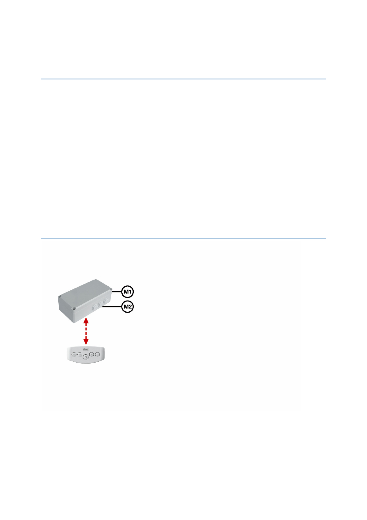
A: Manual operation of drives using the XS MSG2-AP
wireless motor control unit
XS MSG2-AP motor
control unit
Wireless
connection
XS 2B double control
unit for motor 1 and
motor 2
The XS system allows drives to be manually actuated using a wireless control
unit.
4
Required equipment:
• XS MSG2-AP motor control unit (with 2 drive connections)
• XS 2B double control unit
• Further XS 2B double control unit may be used for operation from
elsewhere in the room
Procedure:
• Installation of the motor control unit and connection to the drives
• Installation of the XS 2B control unit
• Configuring the control unit on the motor control unit
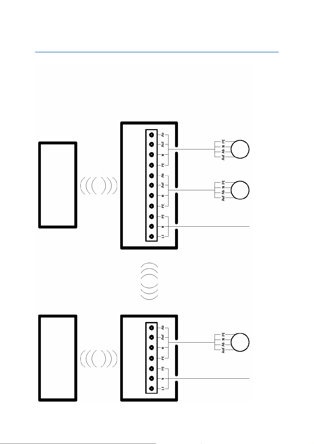
B: Central control systems with Solexa/Arexa
Solexa or Arexa
weather station
Automatic
and alarm
commands
Further MSGs
XS MSG2-AP motor
control unit
Wireless
connection
Double control unit
XS 2B for motor 1 and
Control unit with
display
Wireless
connection
motor 2
The central control system is suitable for use with drives of the same type, e.g.
for awnings only, blinds only or for windows only. The motors receive your
automatic commands centrally from the weather station and can be individually
and manually actuated using the XS 2B double control unit.
Required equipment:
• Solexa control set (for the control of shades) or Arexa (for the control of
windows), from software version 3.2
• XS MSG2-AP motor control unit (with 2 drive connections)
• XS 2B double control unit
• Further XS 2B double control unit may be used for operation from
elsewhere in the room
5

Procedure:
• Installation of Solexa or Arexa (control unit and weather station), see
Solexa/Arexa manual
• Installation of the motor control unit and connection to the drives
• Installation of the XS 2B control unit
• Commissioning of Solexa/Arexa including configuration of wireless
connections between controls and weather station and basic setting of the
drives connected to the Solexa/Arexa systems using the Solexa/Arexa
control unit (see Solexa/Arexa manual)
• Configuring the weather station to the motor control unit
• Configuring the XS 2B control unit on the motor control unit
• Setting the automatic functions for all drives using the Solexa/Arexa
controls (see Solexa/Arexa manual)
The described situation only allows the setting of a shade and/or window
opening position for the drives on the Solexa/ Arexa weather station (M1). It is
not possible to save an operating position for the drives on the motor control
unit (M2, M3) using the XS 2B control unit; an XS 1B-D control unit with display
is required.
For the procedure for saving an operating position, please see the "Basic
Settings" chapter for drives using the XS 1B-D control unit. In the event that the
XS 1B-D is subsequently not used for manual operation, this can be
disconnected from the system in accordance with the basic set-up, and
removed.
6
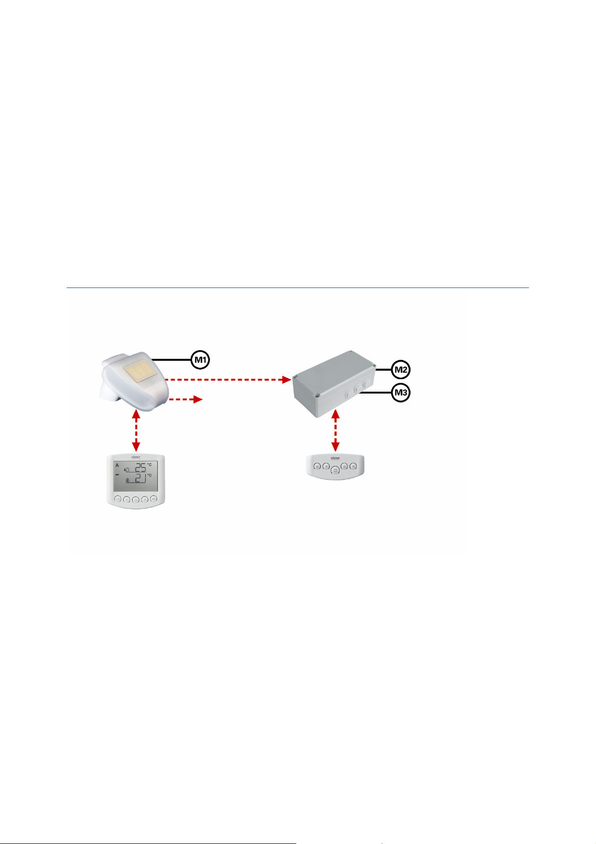
C: Individual automatic control using Solexa/Arexa
Solexa or Arexa
weather station
Wireless
connection
Control unit with
display
Weather data
(wireless)
Further MSGs.
XS 1B-D control
unit, shades or
windows (M2)
XS MSG2-AP motor
control unit
Wireless
connection
XS 1B-D control
unit, shades or
windows (M3)
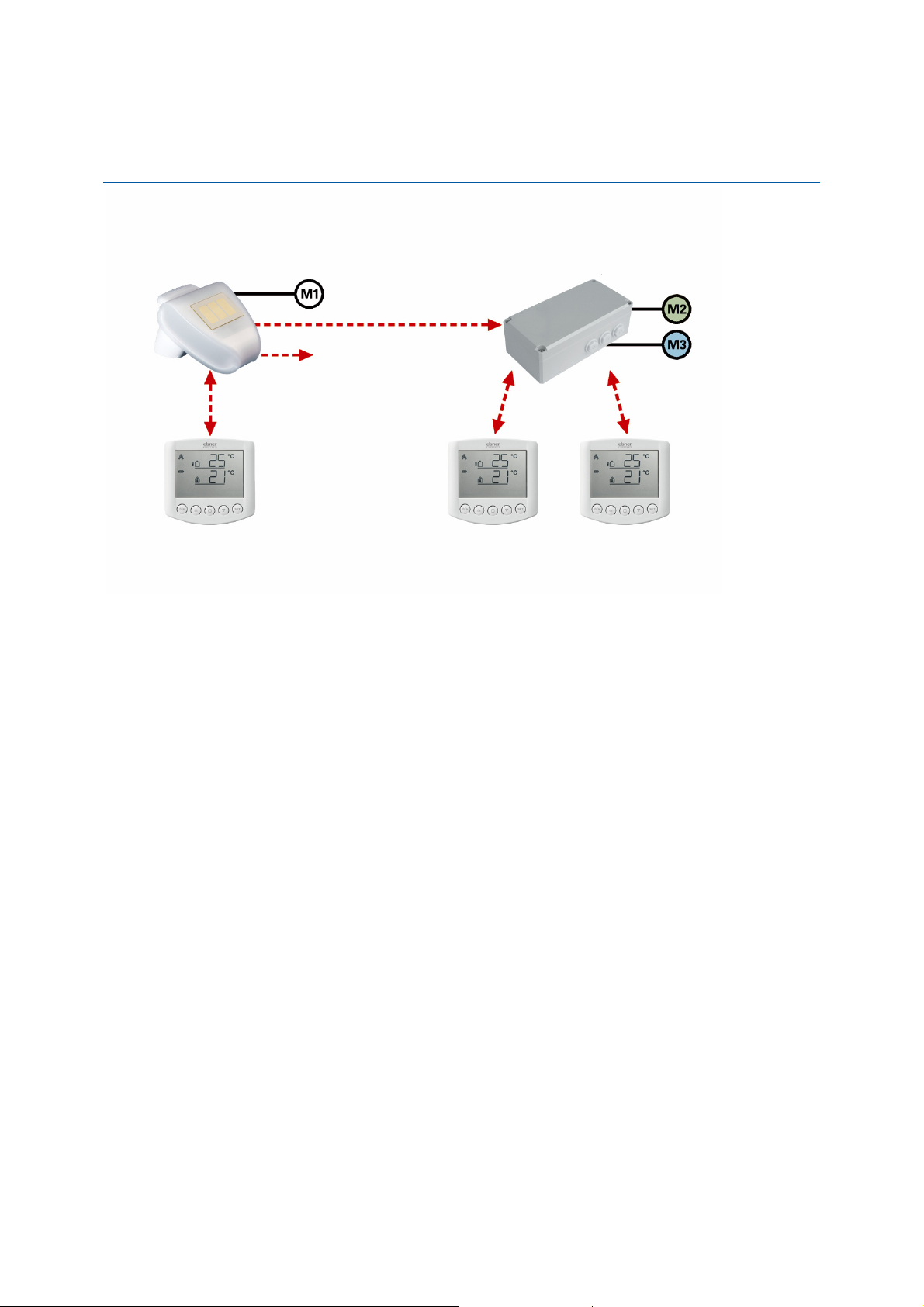
Individual automatic control allows the connection of different drives, such as an
awning to weather station, or a blind or a window to a motor control unit. Each
drive has its own automatic control, which can be set using the XS 1B-D wireless
control unit with display.
Both drives on the motor control unit (M2, M3) can also be treated as a group
when these are of the same type. The motors are both set up over a common XS
1B-D control unit, have the same automatic behaviour and actuate in parallel.
Up to two XS 2B double control units with simple Up/Down buttons can be
configured to the motor control unit in order to be able to actuate the drives (M2,
M3) from elsewhere in the room.
Required equipment:
• Solexa or Arexa control set, from software version 3.2
• XS MSG2-AP motor control unit (with 2 drive connections)
• For each drive which shall be independently controlled, 1 XS 1B-D control
unit with display (maximum of two for XS MSG2-AP). Parallel operation for
both drives with XS MSG2-AP as a group is also possible (with one XS 1BD control unit only).
• Up to two further XS 2B double control units may be used (for operation
from elsewhere in the room)
7

Procedure:
• Installation of Solexa or Arexa (control unit and weather station), see
Solexa/Arexa manual
• Installation of the motor control unit and connection to the drives
• Installation of the control unit
• Commissioning of Solexa/Arexa including configuration of wireless
connections between controls and weather station and basic setting of the
drives connected to the Solexa/Arexa systems using the Solexa/Arexa
control unit (see Solexa/Arexa manual)
• Configuring the weather station to the motor control unit
• Configuring the control units to the motor control unit
• Basic set-up of the drives to the motor control unit using the respective
XS 1B-D (control unit with display)
• Setting the automatic functions for all drives connected to the Solexa/Arexa
systems using the Solexa/Arexa control unit (see Solexa/Arexa manual)
• Setting the automatic functions for the drives to the motor control unit
using the respective XS 1B-D
D: Combinations of central automation and individual
automation
Multiple wireless motor control units can be configured to the weather station
using Solexa or Arexa. The drives connected to them can be controlled on a
central or separate basis.
8

Installation
Procedure
Carefully read the installation recommendations and instructions for the
individual devices through. First, assemble all devices in the system and install
all drive and power supply cabling. Insert batteries in the control units.
Then check all connections and proceed with commissioning.
Installation notes
Warning, mains voltage! National legal regulations are to be
observed.
Installation, testing, commissioning and fault repair may only be carried out by a
qualified electrician. Shut off the voltage to all cables to be fitted and take safety
precautions against unintended activation.
The devices are intended exclusively for appropriate use. Any improper
alteration or non-observance of the operating instructions will void any warranty
or guarantee claim.
After unpacking, the devices shall be checked immediately for any possible
mechanical damage. The supplier shall be immediately notified in the event of
any transport damage.
The devices must not be used if damaged.
If it is assumed that danger-free operation of the XS system, individual devices
or the connected drives can no longer be guaranteed, the equipment shall be
taken out of service and secured against unintended operation.
The XS system devices may only be operated as a fixed installation, meaning in
built-in condition and following the completion of all installation and
commissioning work, and only in the intended environment.
Elsner Elektronik shall not be liable for any changes to norms or standards after
the publication of these operating instructions.
9

Notes on radio devices
When performing the layout, ensure that there is sufficient radio range. The
range of wireless control systems is limited by the statutory regulations
governing wireless devices, and by site conditions (if the radio signal must
penetrate walls and ceilings).
A minimum distance of 30 cm must be maintained between wireless
transmitters in order not to compromise the quality of reception. Control units as
well as motor control units and the weather station should therefore be
positioned at a sufficient distance from other wireless transmitters. Powerful
local transmission sources (such as wireless headphones) which transmit on the
same frequency (868.2 MHz) may interfere with reception. The control units
should also not be installed in direct proximity to metallic surfaces.
Safety information
for automatic and alarm functions
Any power failure to the motor control units or weather station will mean that
the connected drives can no longer be operated! Should full functionality also be
ensured in the event of failed power supply, an emergency generator with
appropriate switching from the mains network shall also be installed on-site for
emergency use.
Settings saved in the software (motor control unit and control units) will remain
unaffected by any power failure. Once the power supply is restored, the control
system will be set to automatic mode.
If the wireless connection between te control unit and the motor control unit fails
(for example from a wireless malfunction or drained batteries in the control
unit), manual access is no more possible. The XS 1B-D control units with
displays retain control in their current mode (manual or automatic). Automatic
mode will continue operating as set up until wireless connection is reestablished, although without taking the indoor temperature into account. Wind
and rain protection functionality remains active also even when manual mode is
set.
Normal automatic mode will continue to operate on XS 2B double control units.
In the event of any interruption to the wireless connection between the weather
station and the motor control unit, the drives will actuate to their safety position
(shades will be retracted, windows will be closed). The XS 1B-D unit screen will
display the message ER (error, malfunction) instead of weather data.
10
Should cleaning or maintenance work be performed in proximity to the shades
or windows, the control system (weather stations and motor control units) must
be without voltage by tripping the fuse fitted on site, and secured against reactivation. This is to ensure that the switched-off drives cannot operate.
A certain amount of time may pass before falling rain is recognised by the
weather station, depending on the rain amount and outdoor temperature.
Please also bear in mind that in the event of a power failure and rainfall, external
awnings will not be automatically retracted if no emergency generator is
installed.
Note that sun protection equipment rails which are externally mounted can ice
up. Operating awnings or blinds under such conditions can damage the shades
and drive.
Please ensure that no one is able to enter the operating areas
of electrically operated equipment components (danger of
crushing!). The relevant construction rules must be observed.
11
XS system Solexa/Arexa connection overview
r
g
r
Further optional XS control unit
(dependent on
usage/configuration)
Wireless
communication
XS control unit
(battery-operated)
ht moto
Motor
Motor
230V AC mains power supply
XS MSG2-AP motor control unit
Wireless
communication
Mains Left motor Ri
Wireless
communication
Control unit
Solexa or Arexa
(battery-operated)
Weather station
Mains Moto
230V AC mains power supply
Motor
12
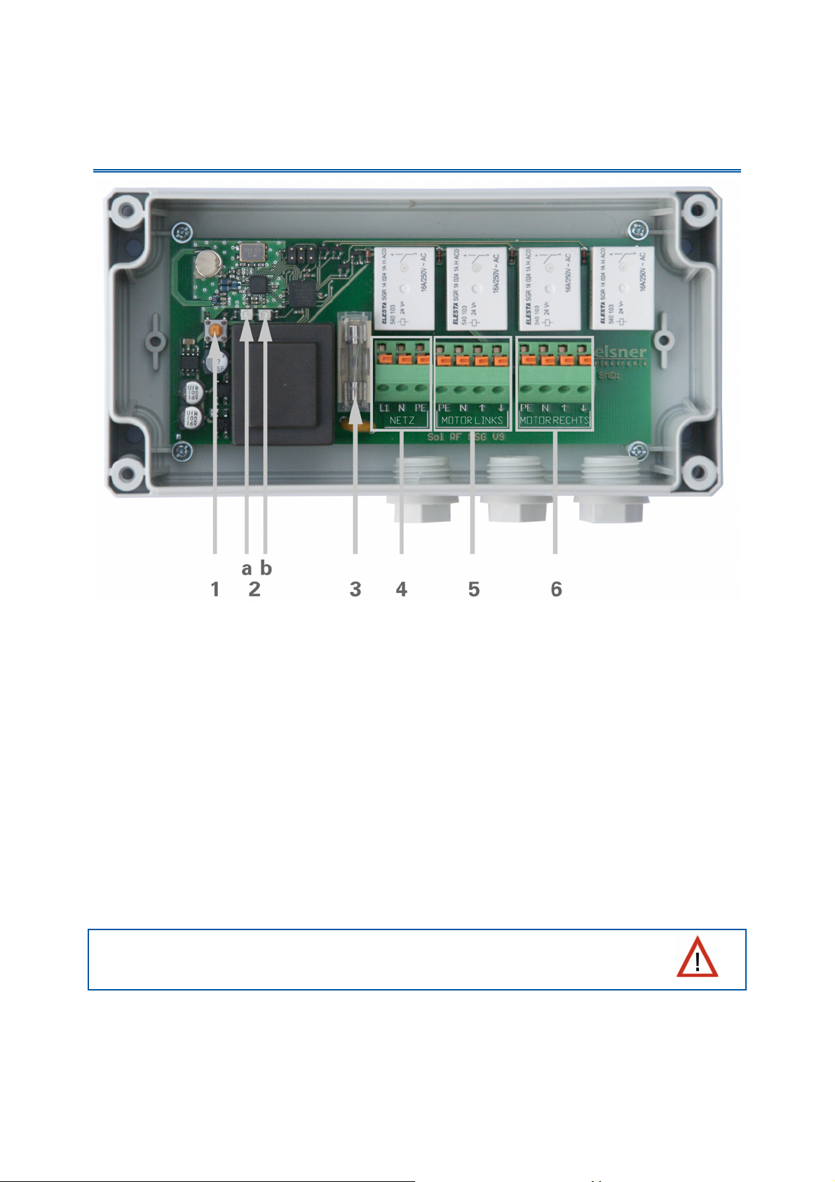
Fitting of the XS MSG2-AP motor control unit and
connection to the drives
1 Configure/Delete button
2a/b LEDs
3 T6,3 A microfuse
4 "Mains" L1/N/PE mains power connection
5 "Motor Left" PE/N/!/" drive connection
6 "Motor Right" PE/N/!/" drive connection
The XS MSG2-AP motor control unit is fitted with two connection points for
drives ("Left" and "Right" connections). Parallel switching of further drives from a
single connection point is possible. Check whether a group control relay is
required by the motor manufacturer. Group control relays can be obtained from
Elsner Elektronik or from the motor manufacturer.
Setting motors in parallel which are not suitable for this
purpose will damage these and the motor control unit.
Motors with a power input exceeding 1000 watt must be operated through a
relay or contactor with its own power supply.
13

We offer appropriate power adaptors for direct current drives. Where required,
we will need you to indicate the motor types, the manufacturer and – if available
– the technical specifications.
Run the power supply and drive connection cable through the grommets and
connect the voltage (L1/N/PE) and "Left" and "Right" drives (PE/N/Up/Down) to
the terminals designated for this purpose. Ensure that the connections are
correct:
Up #: Retract shade / close window ("safety position"),
Down $: Extend the shade, open window.
14
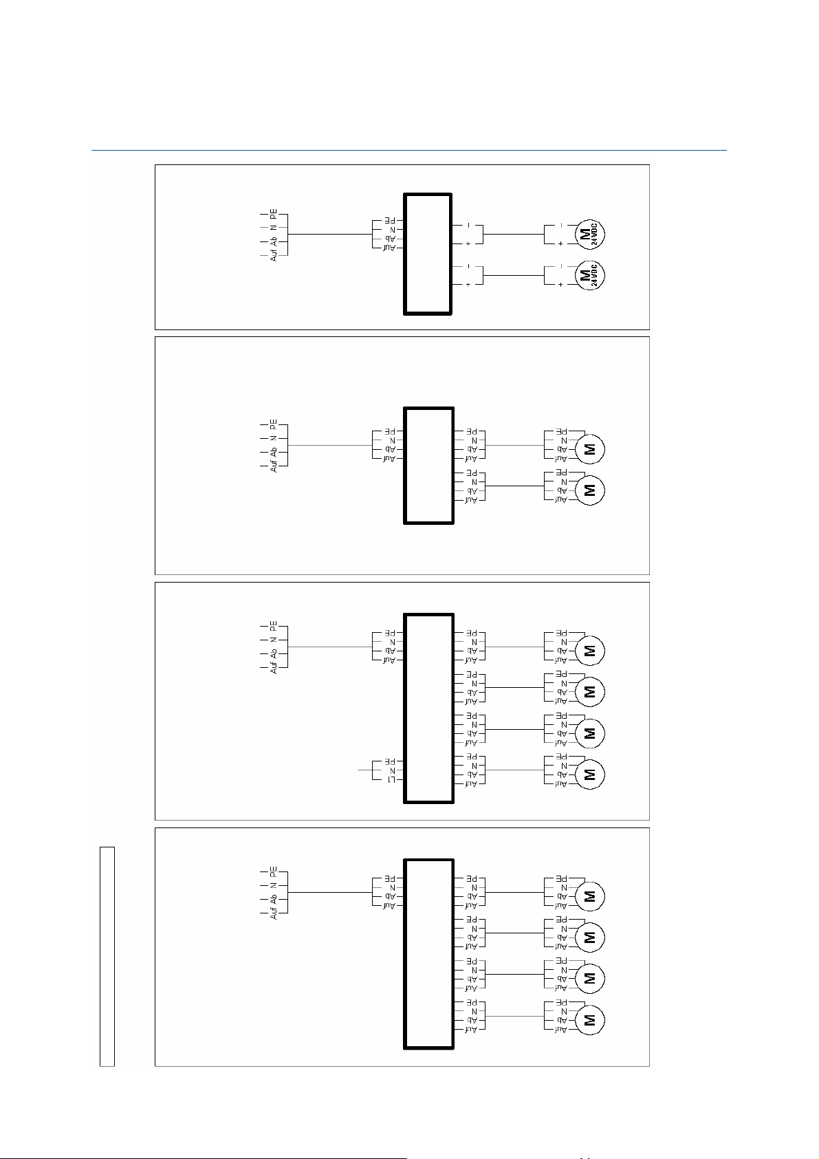
Examples of multiple drives connected as a group to a single
connection
motor control device
Drive group with 12 V or
24 V direct current
Drive group with a total output of
motors
less than 1000 Watt • Motors with no integrated group
control relay
XS motor connection for
motor control device
XS motor connection for
WGDC-2S power
adaptor, 12 V/24 V
variable jumpers
On-site
junction box
WGGS-2 group
control relay, for 2
drives, max. 1000
Control of 12 V or 24 V direct
current motors (variable jumpers),
tot. max 2 A
•
Drive group with a total output of
less than 1000 Watt • Motors with or with no integrated
•
group control relay
motor control device
XS motor connection for
motor control device
XS motor connection for
WG-N-GS-4 group control relay,
for 4 drives, max. 600 Watt each
power supply
230 V L/N/PE mains
Connection examples for more drives
Drive group with a total output of
less than 1000 Watt • Motors with no integrated group
control relay
•
WGGS-4 group control relay
15
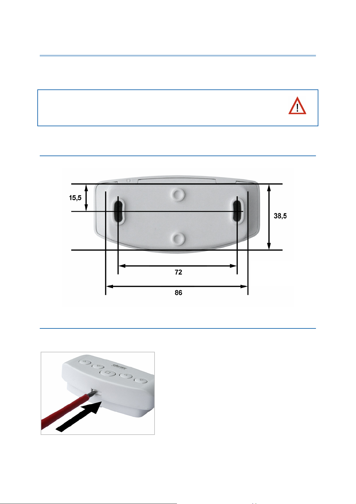
Installing the XS 2B double control unit
The control unit is battery-powered and communicates wirelessly with the motor
control unit. No connection cables are therefore required.
The control unit must only be installed and used in dry,
interior spaces. Relative air humidity must not exceed 80%.
Avoid condensation.
Rear view and drill sketch
All values in mm, may vary due to technical requirements.
Inserting the batteries
The battery compartment is located inside the housing.
Open the control unit by releasing the catch
on the bottom of the housing. To do this,
press a screwdriver directly into the slot.
Dimensions in mm
Masse en mm
16
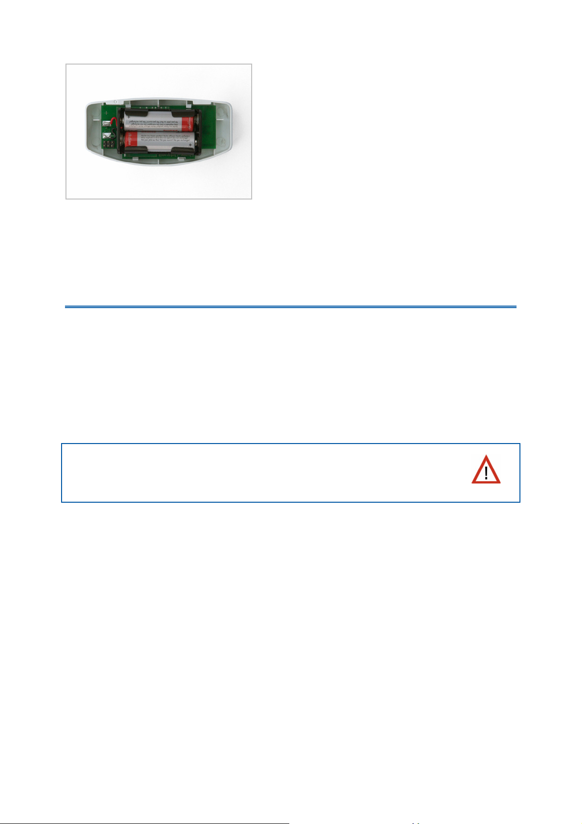
Check that the polarity of the batteries is
correct. Two commercially available AA type
(Mignon/ LR6) batteries (1.5 V) or
rechargeable batteries (1.2 V) are required.
Close the housing by lowering the forward part of the housing (with the PCB)
from above over the rear panel. The latch mechanism on the underside must
engage with a clear "click".
Installation of the XS 1B-D control unit
The control unit is battery-powered and communicates wirelessly with the motor
control unit.
Avoid selecting an installation position in direct sunlight, as this will result in
incorrect indoor temperature measurements. The measuring sensor is built into
the underside of the control unit. For the same reason, the control unit should
not be installed above a radiator. Please also ensure that no direct draft from
windows or doors distorts the measurement values.
The control unit must only be installed and used in dry, interior
spaces. Relative air humidity must not exceed 80%. Avoid
condensation.
17
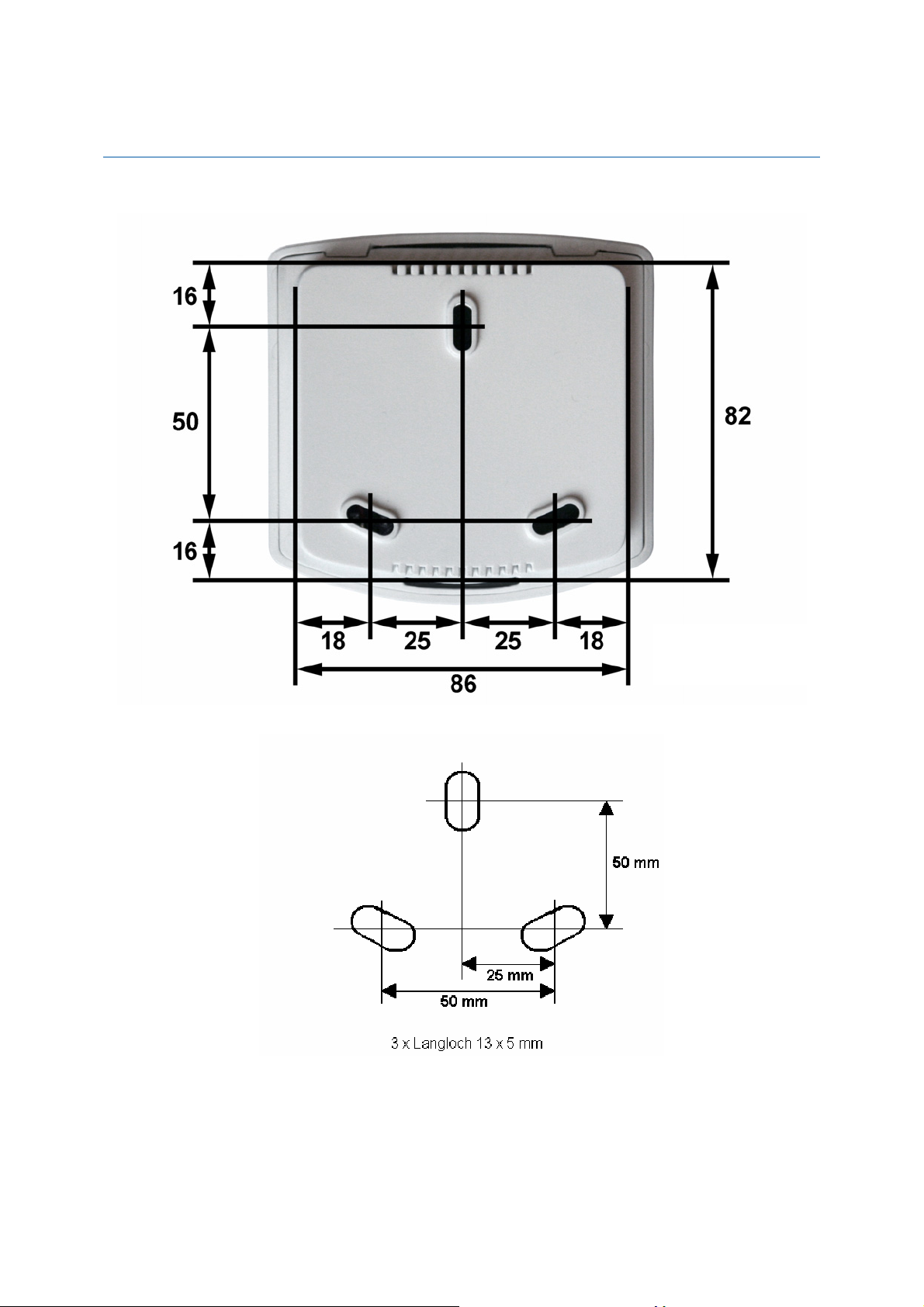
Rear view and drill sketch
All values in mm, may vary due to technical requirements.
Dimensions in mm
18

Inserting the batteries
The battery compartment is located inside the housing.
Open the control unit by releasing the catch
on the bottom of the housing. To do this,
press a screwdriver directly into the slot.
Check that the polarity of the batteries is
correct. Two commercially available AA type
(Mignon/ LR6) batteries (1.5 V) or
rechargeable batteries (1.2 V) are required.
Close the housing by lowering the forward part of the housing (with the PCB)
from above over the rear panel. The latch mechanism on the underside must
engage with a clear "click".
19
 Loading...