


EN
WS1000 Connect
Building controls
Article numbers 60241-60246
Installation, setting, operation


1 Contents
1. Description ................................................... 5
1.1. Area/field of application .................................................................... 6
Overview of connection and control options ....................................................... 8
Scope of delivery .................................................................................................... 8
Automatic functions of the motors and devices .................................................. 8
1.1.1. Technical Data, central unit WS1000 Connect .................................................. 12
2. Operation .................................................... 13
2.1. Start page ........................................................................................ 14
2.1.1. Weather data display ........................................................................................... 15
2.2. The touch display ............................................................................. 17
2.3. Operate motors and devices manually ............................................. 17
2.3.1. The manual menu ................................................................................................ 17
Examples of manual pages .................................................................................. 18
Key functions and display fields .......................................................................... 19
Info icons ............................................................................................................... 21
2.3.2. External keys ........................................................................................................ 24
2.3.3. Internal keys (group keys) ................................................................................... 24
2.3.4. Remote control .................................................................................................... 24
2.3.5. WS1000 Connect App .......................................................................................... 24
2.3.6. Navigate in the system menu ............................................................................. 25
2.4. Internet (browser) ............................................................................ 26
2.5. Slide show ....................................................................................... 27
3. Automatic ................................................... 29
3.1. Set-up automatic ............................................................................. 30
3.1.1. Safety notice for automatic and alarm functions .............................................. 31
Power failure, maintenance works, etc. (restart of control) .............................. 31
3.2. Adjust general automatic settings ................................................... 32
3.2.1. Change twilight .................................................................................................... 32
3.2.2. Change travel delay (shades) ............................................................................ 32
3.2.3. Set timer ............................................................................................................... 32
3.2.4. Adjust ventilation lock (air-conditioning unit) ................................................... 33
3.2.5. Set night back cooling (ventilation) ................................................................... 33
3.2.6. Adjust frost alarm ................................................................................................ 34
3.2.7. Set movement limit (windows) .......................................................................... 35
3.2.8. Set wind delay (shades) ...................................................................................... 35
3.2.9. Specify automatic reset ....................................................................................... 36
3.3. Set automatic for motors and devices ............................................. 36
3.3.1. Motors and devices without automatic functions ............................................. 36
3.3.2. Set automatic sun protection ............................................................................. 36
Elsner Elektronik GmbH • Sohlengrund 16 • 75395 Ostelsheim • Germany
WS1000 Connect controls • from software version 1.09
Version: 15.07.2019 • Technical changes and errors excepted.

2 Contents
Alarm functions .................................................................................................... 37
Shade settings ...................................................................................................... 37
Set-up automatic .................................................................................................. 37
3.3.3. Set automatic window controls .......................................................................... 43
Alarm functions .................................................................................................... 44
Ventilation settings ............................................................................................... 44
Set-up automatic .................................................................................................. 44
3.3.4. Set automatic ventilation .................................................................................... 49
Alarm functions .................................................................................................... 50
Ventilation settings ............................................................................................... 50
Set-up automatic .................................................................................................. 50
Ventilation modes, radio roof fan ....................................................................... 54
3.3.5. Set automatic heating ......................................................................................... 54
3.3.6. Set automatic air-conditioning ........................................................................... 55
3.3.7. Set automatic light controls ................................................................................ 57
3.3.8. Set automatic gutter heating .............................................................................. 58
3.3.9. Set alarm .............................................................................................................. 58
Alarm output ......................................................................................................... 58
Set motion detector .............................................................................................. 59
4. Installation and commissioning .................. 61
4.1. Procedure ......................................................................................... 62
4.1.1. Operating system ................................................................................................ 62
4.1.2. Protective film ...................................................................................................... 62
4.1.3. Installation notes ................................................................................................. 62
4.1.4. Notes on wireless equipment ............................................................................. 63
4.1.5. Safety notice for automatic and alarm functions .............................................. 63
Power failure, maintenance works, etc. (restart of control) .............................. 64
4.2. Installation of the weather station: see leaflet ................................ 64
4.3. Installation of the indoor sensor: see leaflet ................................... 64
4.4. Installation of the controls: see leaflet ............................................ 64
4.4.1. Connect motors and devices .............................................................................. 65
Connect motor groups ......................................................................................... 65
Connect device to multifunction outputs ........................................................... 65
Connect device to multifunction inputs .............................................................. 66
Connect hand button ............................................................................................ 66
Connect motors and devices wirelessly with the controls ................................ 66
4.4.2. Start controls ........................................................................................................ 67
4.4.3. Check function of the sensors ............................................................................ 67
5. Basic setting ............................................... 69
5.1. The "Installation" menu ................................................................... 70
5.1.1. Set motors and motor groups ............................................................................ 71
Elsner Elektronik GmbH • Sohlengrund 16 • 75395 Ostelsheim • Germany
WS1000 Connect controls • from software version 1.09
Version: 15.07.2019 • Technical changes and errors excepted.

3 Contents
Tips on connecting windows ............................................................................... 74
5.1.2. Set multifunction outputs ................................................................................... 74
5.1.3. Set multifunction inputs ...................................................................................... 75
5.1.4. Wireless connections .......................................................................................... 76
5.1.5. Allocate external keys ......................................................................................... 83
5.1.6. Allocate internal keys (group keys) .................................................................... 84
5.1.7. Scenes .................................................................................................................. 85
5.1.8. Start page ............................................................................................................. 85
5.1.9. Manual page ........................................................................................................ 86
5.1.10.Weather data ....................................................................................................... 87
5.2. Set up WS1000 ................................................................................ 88
5.2.1. Settings ................................................................................................................. 88
Enter time and date manually ............................................................................. 89
Change language .................................................................................................. 89
Set up screen ........................................................................................................ 89
Switch key tone off/on .......................................................................................... 90
Select time zone .................................................................................................... 90
Enter location ........................................................................................................ 91
5.2.2. Service settings .................................................................................................... 91
Reset (restart) ........................................................................................................ 91
Factory settings ..................................................................................................... 92
Internal area .......................................................................................................... 92
Remote set up/remote maintenance ................................................................... 92
5.2.3. Access code .......................................................................................................... 93
5.2.4. Using an SD card ................................................................................................. 94
Save and load configuration data ....................................................................... 94
Show pictures on the display .............................................................................. 95
Internet .................................................................................................................. 95
Device information ............................................................................................... 96
6. Tables, plans, maintenance ........................ 97
6.1. Maintenance and care ...................................................................... 98
Maintenance of the weather station ................................................................... 98
Maintenance of the controls ................................................................................ 98
6.1.1. Units for sun and wind ........................................................................................ 98
6.2. Alarm and error messages ............................................................... 99
Network error ........................................................................................................ 99
Alarm display in the weather data area .............................................................. 99
Smoke alarm ....................................................................................................... 101
Weather station errors ....................................................................................... 101
6.3. Wiring diagrams ............................................................................. 103
Connection examples for multifunction outputs ............................................. 105
6.4. Personal automatic settings data .................................................. 106
Elsner Elektronik GmbH • Sohlengrund 16 • 75395 Ostelsheim • Germany
WS1000 Connect controls • from software version 1.09
Version: 15.07.2019 • Technical changes and errors excepted.
4 Clarification of signs
Installation, inspection, commissioning and troubleshooting of the device
must only be carried out by a competent electrician.
This manual is amended periodically and will be brought into line with new software
releases. The change status (software version and date) can be found in the contents footer.
If you have a device with a later software version, please check
www.elsner-elektronik.de in the menu area "Service" to find out whether a more up-todate version of the manual is available.
Clarification of signs used in this manual
Safety advice.
Safety advice for working on electrical connections, components,
etc.
DANGER!
WARNING!
CAUTION!
ATTENTION!
“Control unit”
“Manual”
... indicates an immediately hazardous situation which will lead to
death or severe injuries if it is not avoided.
... indicates a potentially hazardous situation which may lead to
death or severe injuries if it is not avoided.
... indicates a potentially hazardous situation which may lead to
trivial or minor injuries if it is not avoided.
... indicates a situation which may lead to damage to property if it is
not avoided.
The symbol is followed by a menu path. In this menu the settings
just described can be changed.
The symbol is followed by chapter information with a page number. In this chapter you will find additional information about the
setting just described.

5 Description
1. Description
WS1000 Connect controls • Version: 15.07.2019 • Technical changes and errors excepted.

6 Description
1.1. Area/field of application
The various technical facilities installed in the building are controlled automatically and
operated manually using the WS1000 Connect controls. In order to be able to set
up the system flexibly, both cable connections and wireless channels are available.
The WS1000 Connect is delivered as a set, which includes the sensors needed for
room climate and weather data as well as the central unit (display with control electronics). The sensor values are shown in the display and are the basis of the automatic
controls.
Functions and properties of the central unit WS1000 Connect:
• Colour touch display 10.1 inch, for manual operation, system set up and for
setting the basic and automatic functions
• Network connection by LAN or WLAN
• Browser for viewing websites, streaming, etc.
• Remote access via network for system setup, diagnostics etc. Approval by the
user required
• Slide show from SD card as screen saver
• Data storage on SD card (storage of settings)
• Integrated loudspeaker (4 tweeters, 1 broadband speaker)
• Motor outputs (4-10 pcs, depending on model) for electrically powered
- Awnings, blinds, shutters
- Windows, sliding roofs and sliding doors
• 4 multifunction outputs for
- Lights (switching or dimming)
- Heating (on/off), cooling (on/off), ventilators (on/off)
- Alarms
- Gutter heating
• 16 scenes for calling individually set movement positions and switch states
With a scene, several motors and devices are addressed simultaneously so a
suitable ambience is created with one press of a button ("TV", "Eating", etc.).
• 4 multifunction inputs for
- Motion detector:
- Smoke detector:
- Climate detector (prevent ventilation if external
air-conditioning/heating is active)
- Safety contact (motors in safe position,
prevent exhaust air, start incoming air)
- Closed contact (sliding door closed message)
- Impulse for automatic reset
- Binary contact for free use
• 10 key inputs for additional conventional wind sensor for operating motors
and devices on site
• 32 radio channels for devices with Elsner RF radio protocol
- Sensors WGTH-UP for room temperature, humidity (from version 1.3),
WG AQS/TH-UP for room temperature, humidity, CO
WGT (indoor temperature) for measuring at other locations in the room
,
2
WS1000 Connect controls • Version: 15.07.2019 • Technical changes and errors excepted.

7 Description
- Remote control Remo 8 (from version 1.8), Remo pro
- Sensor Corlo P RF, sensor interface RF-B2-UP
- WL400, WL800 and WL-Z ventilation units
- RF-VM ventilation module for connecting fans/circulation air heaters
from other manufacturers
- Wireless relay RF relay for on/off (each from version 5.5),
Heating module RF-HE-ST (from version 5)
- Wireless motor control device RF-MSG for up/down (from version 3.7)
- RF-L wireless dimmer:
The wireless actuators with a production date after 14.01.2016 are compatible with the
WS1000 Connect system. The production date can be found as part of the serial
number which has the following structure "DD MM YY consecutive number".
WARNING!
The radio transmission takes place over a non-exclusively
available transmission channel!
The device is not suited for applications outside the field of safety equipment,
such as emergency stop and alarm equipment.
Functions and properties of the indoor sensor:
• Temperature measurement
• Humidity measurement
Functions and properties of the weather station:
• Brightness measurement (sun sensor)
• Temperature measurement
• Wind speed measurement
• Precipitation detection
• GPS receiver for date/time and installation coordinates (for sun position
calculation)
WS1000 Connect controls • Version: 15.07.2019 • Technical changes and errors excepted.
Central
Weather
Station
Indoor
Sensors
4 Multifunctional
Inputs
• Motion Detector
• Smoke Detector
• Climate Signaller
(Status heating/cooling)
• Security Contact
• Closed Contact (for sliding door)
• Impulse (for automatic reset)
Wireless
Remote Control
Button
10 Buttons
• Single Manual Button
• Double Manual Button
Drive
Outputs
• Awning
• Blind
• Roller Shutter
• Window
• Sliding Door
4 Multifunctional
Outputs
• Heating
• AC/Cooling
• Light
• Dimmer
• Supply Air
• Alarm System
• Gutter Heating
Wireless
Ventilation Units
Wireless
Actuators
(Relay, MSG,
Dimmer)
Internet
App
(W)LAN
8 Description
Overview of connection and control options
Scope of delivery
• Central control and operating unit with flush installation box and installation
accessories
• Weather station with connection accessories
• Indoor sensor with frame
(In addition, you need a device socket ø 60 mm, 42 mm deep)
Automatic functions of the motors and devices
Devices (e.g. lights) connected via the "Dimming" output do not have automatic
functions. However, they can be operated manually via the display.
Sliding doors do not have automatic functions either. They can be fitted with a To
contact (at the multifunction input) and operated manually via the display.
WS1000 Connect controls • Version: 15.07.2019 • Technical changes and errors excepted.

9 Description
Automatic functions for windows/sliding roofs:
• Open from a selectable indoor temperature (can be switched off)
• Open from a selectable humidity in the room (can be switched off)
• Open according to the CO
switched off)
• Close if the incoming air temperature is higher than the room temperature (can
be switched off)
• Night back cooling (period can be set)
• Daily force ventilation (period can be set)
• Outside temperature block: Block below a selectable outside temperature (can
be switched off)
• Keep closed in a settable period
• Frost alarm: Close during precipitation below a selectable outside temperature
(can be switched off)
• Wind alarm: Close if a selectable wind speed is exceeded (can be switched off)
• Rain alarm: Close completely or to only provide a gap during rainfall (can be
switched off)
• Close if the cooling/air-conditioning is active
If a motion sensor is connected, windows are closed automatically if there is a burglary
alarm. If a smoke detector is connected, windows are closed automatically if there is a
fire alarm.
Step windows are opened gradually. An opening position can be selected for sliding
windows.
content of the room (only with CO2 sensor, can be
2
Automatic functions for awnings:
• Extend depending on brightness and sun position
or retract irrespective of brightness (extension only manual)
or extend irrespective of brightness (privacy protection, automatic retraction
only if there is a rain or wind alarm)
• Movement position can be set
• Retract until a selectable indoor temperature is reached (can be switched off)
• Outside temperature block: Block below a selectable outside temperature (can
be switched off)
• Frost alarm: Retract during precipitation below a selectable outside
temperature (can be switched off)
• Wind alarm: Retract if a selectable wind speed is exceeded (can be switched
off)
• Rain alarm: Retract during rainfall (can be switched off)
If a smoke detector is connected, awnings are retracted automatically if there is a fire
alarm.
Automatic functions for blinds:
• Close depending on brightness and sun position
or keep open irrespective of brightness (closing only time-controlled or
WS1000 Connect controls • Version: 15.07.2019 • Technical changes and errors excepted.

10 Description
manual)
or keep closed irrespective of brightness (privacy protection, automatic
retraction only if there is a rain or wind alarm) with reversal in order to let in
light
• Movement position and blind position can be set (slat adjustment possible
according to sun height)
• Keep open until a selectable indoor temperature is reached (can be switched
off)
• Close at night/twilight (can be switched off)
• Close daily (period can be set)
• Outside temperature block: Block below a selectable outside temperature (can
be switched off)
• Frost alarm: Retract during precipitation below a selectable outside
temperature (can be switched off)
• Wind alarm: Retract if a selectable wind speed is exceeded (can be switched
off)
• Rain alarm: Retract during rainfall (can be switched off)
If a smoke detector is connected, blinds are closed automatically if there is a fire alarm.
Automatic functions for shutters:
• Close depending on brightness and sun position
or keep open irrespective of brightness (closing only time-controlled or
manual)
or keep closed irrespective of brightness (privacy protection, automatic
retraction only if there is a rain or wind alarm)
• Movement position can be set
• Keep open until a selectable indoor temperature is reached (can be switched
off)
• Close at night/twilight (can be switched off)
• Close daily (period can be set)
• Outside temperature block: Block below a selectable outside temperature (can
be switched off)
• Frost alarm: Retract during precipitation below a selectable outside
temperature (can be switched off)
• Wind alarm: Retract if a selectable wind speed is exceeded (can be switched
off)
• Rain alarm: Retract during rainfall (can be switched off)
If a smoke detector is connected, shutters are closed automatically if there is a fire
alarm.
Automatic functions for heating:
• Switch on during the day below a selectable indoor temperature
• Lowering at night (period and temperature can be set, to which it should be
lowered)
WS1000 Connect controls • Version: 15.07.2019 • Technical changes and errors excepted.

11 Description
If a smoke detector is connected, the heating switches off automatically if there is a
smoke alarm.
Automatic functions for cooling and air-conditioners:
• Switch off during the day below a selectable indoor temperature
• Night mode (period and temperature can be set, to which it should be cooled)
• Prevent ventilation if cooling/air-conditioning is active
If a smoke detector is connected, the cooling switches off automatically if there is a
smoke alarm.
Automatic functions for ventilation:
• Ventilation from a selectable indoor temperature (can be switched off)
• Ventilate from a selectable air humidity in the room (can be switched off)
• Ventilation according to the CO
be switched off)
• Winter switching: Incoming air is closed below a selectable outside
temperature (can be switched off)
• Summer switching: Incoming air is closed if the outside temperature is higher
than the room temperature.
• Minimum and maximum speed of motorised fans can be set
• Night back cooling (period can be set)
• Daily force ventilation (period can be set)
• For roof ventilators WL400/800 also: Circulating air for heat recovery;
circulating air for preventing condensation
• Prevent ventilation if cooling/air-conditioning is active
If a smoke detector is fitted, the ventilation is activated automatically if there is a fire
alarm.
content of the room (only with CO2 sensor, can
2
Automatic functions for light:
• Switch on daily (period can be set, with and without twilight detection)
• Switch on at twilight
• Switch on if there is an alarm (motion/smoke detector)
Automatic functions for gutter heating:
• Switch on within a settable temperature range
Automatic alarms:
• Motion detector: Period when alarm is active can be set. If the alarm is triggered
during this period, all windows close. Normal automatic mode is restored after
5 minutes if there is no new alarm signal
• Smoke detector: If there is an alarm, shades retract (escape routes), windows
open, fans open/switch on (smoke removal) and heating and air-conditioning
WS1000 Connect controls • Version: 15.07.2019 • Technical changes and errors excepted.

12 Description
switch off. Manual operation is not possible. An acoustic warning signal is
issued by the control
1.1.1. Technical Data, central unit WS1000
Connect
Housing Glass, plastic
Colour black
Assembly Flush / cavity wall
Dimensions Display front approx. 279 x 185 (W x H, mm),
Display resolution 1280 × 800 px
Weight approx. 2.2 kg for model WS1000 Connect-10
Ambient temperature Operation 0...+45°C, Storage -30…+70°C,
Operating voltage 230V AC, 50 Hz
Power consumption Readiness max. 17 W
Load capacity
Motor outputs
Radio frequency radio channels
The product is compliant with the provisions of EU Directives.
Installation depth approx. 29 mm,
Concealed box approx. 254 × 171 × 85 (W × H × D, mm)
Avoid condensation
per motor output, max. 400 W,
total max. 1.5 kW
868.2 MHz (Elsner RF).
WS1000 Connect controls • Version: 15.07.2019 • Technical changes and errors excepted.

13 Operation
2. Operation
WS1000 Connect controls • Version: 15.07.2019 • Technical changes and errors excepted.
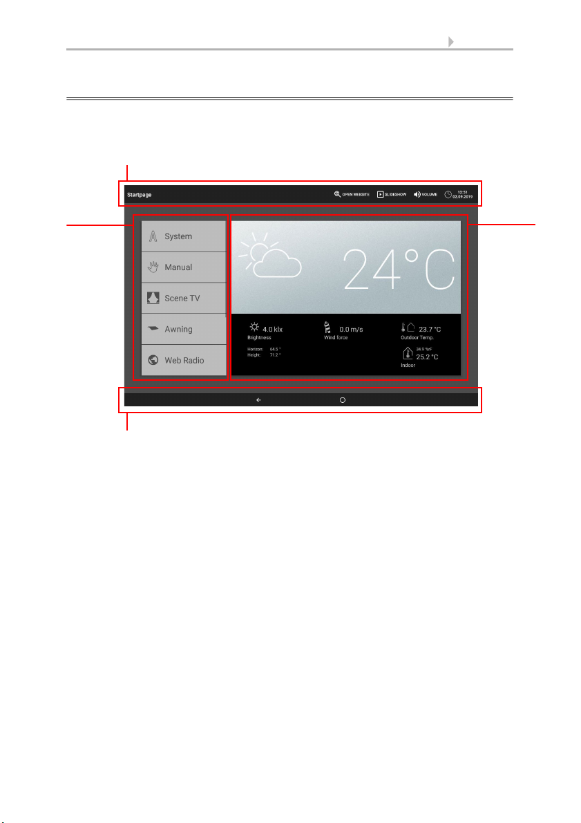
14 Operation
Bottom navigation menu
Display
and
setting
area
Top menu bar
Menu
2.1. Start page
With the WS1000 Connect controls you can control the connected technology centrally, e.g. raise and lower shades, switch devices on and off and dim lights. All the settings are also made on the display.
Top menu bar:
The Internet browser (open website) and Volume functions can be accessed at any
time via the top menu bar. Time and date are displayed. Additionally, the start key for
the slide show appears here as soon as an SD card with pictures is loaded.
Menu on left (Start menu):
The menu on the left-hand side contains the System menu, with which you can reach
all the basic and automatic settings.
Connected motors and devices are operated by hand using the Manual menu.
This includes the selected Favourites for manual operation and the websites saved as
Bookmarks.
So that a motor/device is displayed in the Manual menu and/or as a Favourite, the display has to be activated in the setting "Manual menu" in the installation settings.
System > Installation > Motor/Multif.output > Manual menu
Right-hand display and settings area:
The control unit displays the current weather data as its start page .
WS1000 Connect controls • Version: 15.07.2019 • Technical changes and errors excepted.
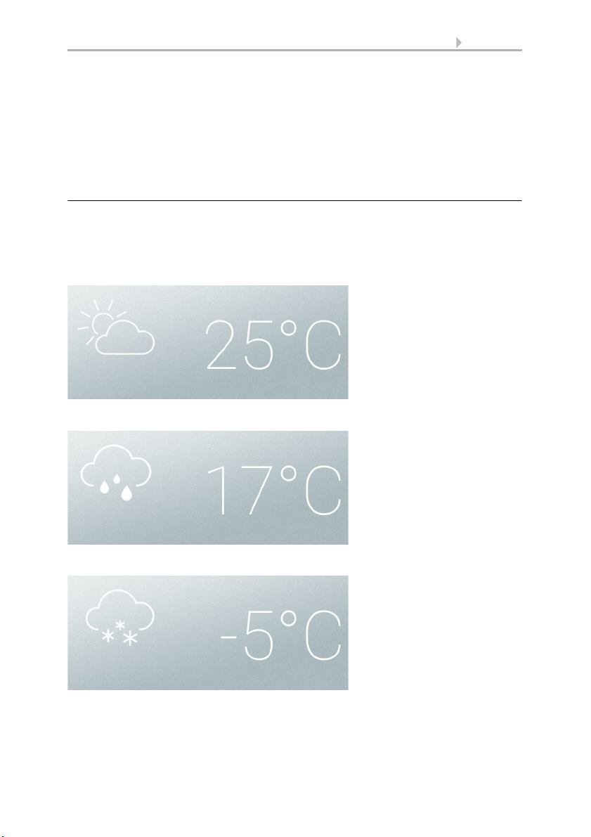
15 Operation
Sunny or cloudy
Rain
If there is a rain message and
there are temperatures
above -3 °C it is raining
Snow
If there is a rain message and
there are temperatures
below -3 °C it is snowing.
The functions / parameters are displayed here when navigating in the settings (submenus).
Bottom navigation menu:
On the bottom edge of the display you will see a Navigation menu with "Back"
arrow and a circle, which takes you back directly to the start page.
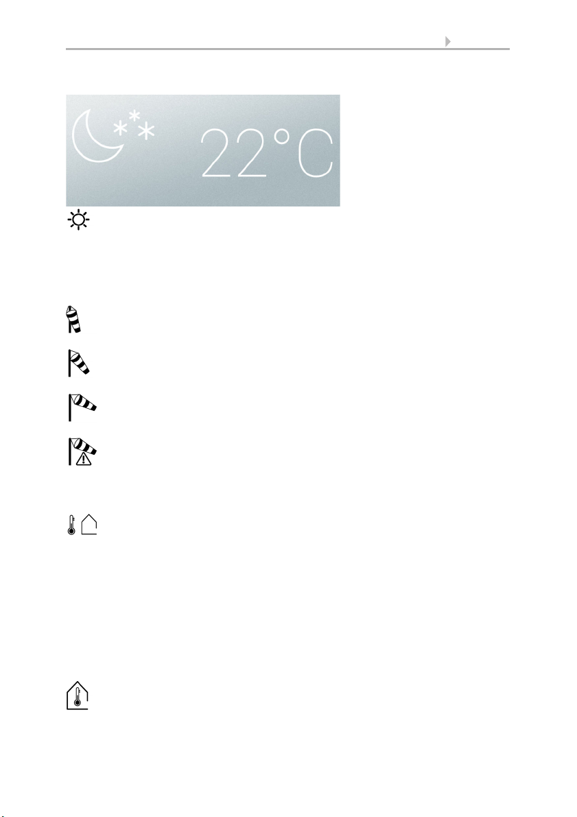
2.1.1. Weather data display
The current weather and indoor data is displayed in the large display area on the right.
General weather symbol and outside temperature:
Sun data:
WS1000 Connect controls • Version: 15.07.2019 • Technical changes and errors excepted.
16 Operation
Night
Light intensity: Brightness in lux (lx) or kilolux (klx)
Direction: Compass direction (azimuth) in degrees
Height: Elevation above the horizon in degrees
Calm: up to 1.9 m/s
Weak wind: 2.0 to 9.9 m/s
Strong wind: from 10.0 m/s
If a wind alarm has been triggered for a motor, a warning is displayed
next to the wind symbol.
Outside temperature at the weather station in degrees Celsius (°C)
Temperatures in degrees Celsius (°C)
Humidity in %rF
Wind:
The wind speed is displayed in metres per second (m/s) and the windsock changes:
Outside temperature:
For the outside temperature value, night back cooling, frost alarm and window
movement limit are shown alternately as soon as the corresponding function is ac-
tive.
3.3. Set night back cooling (ventilation)
3.3. Adjust frost alarm
3.3. Set movement limit (windows)
Indoor data:
WS1000 Connect controls • Version: 15.07.2019 • Technical changes and errors excepted.

17 Operation
You can set which indoor data should be displayed (e..g. if several sensors are connected).
System > Installation > Weather display
6.1. Indoor sensor for weather data display
2.2. The touch display
The manual controls and the default setting of the automatic functions are performed
via the permanently installed touch display of the controls. The button surfaces are actuated by pressing the display in the respective area. If a key is pressed, there is optical
feedback and a brief audio signal is emitted. The key tone can be switched off.
System > Set up WS1000 > Settings > Key tone
5.2.1. Einstellungen > Tastenton abschalten/einschalten, Page 96
Operating the display with long fingernails will not damage the display screen or the
touch function. Touching with very hard and pointed objects (e.g. made from glass,
gemstone or metal) should be avoided because this can cause scratches.
2.3. Operate motors and devices manually
The start menu is on the left of the start page. Beneath the system and manual menu
key, selected favourites are displayed for the manual operations and the websites
saved as bookmarks. So that a motor/device is displayed in as a favourite, the display
has to be activated in the setting "Manual menu" in the installation settings.
You can change the display sequence in the start menu:
System > Installation > Start page
5.1.8. Startseite
2.3.1. The manual menu
Start menu > Manual
The page for manual operation is reached via the Manual menu key on the start page.
So that a motor/device is displayed here, the display has to be activated in the setting
"Manual menu" in the installation settings. Either individual motors/devices and group
keys are displayed, or subject groups.
A group key summarises a motor or device with the same function (e.g. all blinds in
a room). These motors/devices are operated simultaneously with the key.
5.1.6. Interne Taster (Gruppentasten) zuordnen, Page 89
Different functions are collated in a subject group in order to create more overview
in the manual menu. The following groups are available:
• Central function: for group keys and scenes
• All visible functions: all functions, not selection possible
• Room control: for heating, air-conditioning and fans
WS1000 Connect controls • Version: 15.07.2019 • Technical changes and errors excepted.

18 Operation
Position
information
Sliding bar position
Selection
Control
buttons
Field for
info icons
• Floors: for different floors in a building
• Output for motors and devices
• Input: for sensors
You can change the display sequence in the manual menu here:
System > Installation > Manual page
5.1.9. Manuell-Seite, Page 91
As soon as a subject group has been activated, motors and
devices are no longer displayed in the manual menu!
Examples of manual pages
Blinds in automatic mode:
WS1000 Connect controls • Version: 15.07.2019 • Technical changes and errors excepted.
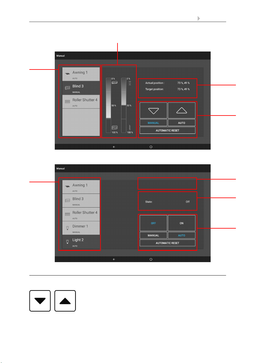
Blind after manual movement:
Position
information
Sliding bar position
Selection
Control
buttons
Status
information
Selection
Control
buttons
Field for
info icons
Switch lights to automatic mode:
19 Operation
Key functions and display fields
Up/down keys:
The keys Up and Down have a timer automatic.
WS1000 Connect controls • Version: 15.07.2019 • Technical changes and errors excepted.

20 Operation
Fan OFF
(stopped,
flap closed)
Circulation air mode
Press
Speed higher
Speed lower
(to OFF)
Press
Exhaust air mode
Speed lower
(to OFF)
Speed higher
A motor can be precisely positions by briefly pressing it (less than 1 second, short audio signal). For blinds and shutters, only a brief step movement command is issued. If
the key is held for more than 1 second (higher audio signal: state signal), the motor
moves automatically to the end position. Brief pressing of the opposite direction stops
the motor.
For shades and windows, the movement position is shown in percent above the Up-/
Down buttons (for blinds, also the slat position). For radio motor control units, the position shown can deviate from the movement position set in the automatic mode by up
to 2%.
Ventilators WL400 and WL800 are switched by briefly pressing (less than 1 second,
short audio signal) in 10%-steps (total of 10 ventilation steps). Pressing a key for longer
continuously changes the speed. If the key is released, the change in speed stops.
In rare cases, the speed continues to change after the key has been released because
of radio problems. The please press the opposite direction briefly.
Each time the OFF state is reached, the speed change stops automatically, so that a
direct change between exhaust and circulation modes is impossible.
Manual/Automatic:
Whether a motor or device is in automatic mode or has been operated manually, can
be detected from the blue marking on the key and the text in the list on the left. You
can switch mode by pressing a key.
After any manual operation, the drive or unit remains in manual mode. The automatic
functions are then switched off, only rain and wind protection are executed. Automatic
mode can be activated again manually (key "Auto" or "Automatic reset"). In addition,
an automatic reset can be activated in the automatic settings of each motor group and
each device, both at a fixed time and after a manual operation.
WS1000 Connect controls • Version: 15.07.2019 • Technical changes and errors excepted.

21 Operation
If a motor group is currently blocked for manual operation by
a rain, wind or frost alarm, no Up/down arrow keys are displayed. The red icons show the alarm for the relevant motor
groups.
Smoke alarm!
Manual operation blocked.
Wind alarm!
Manual operation blocked.
Rain alarm!
Manual operation blocked.
Frost alarm!
Manual operation blocked.
Block active!
E.g. ventilation prevented because of active fire, block as a result of safety
contact.
Info icons
Alongside position and status information, icons on the manual page show how automatic mode is currently working and whether there is a block, which inhibits manual
operation for example.
Icon GREY: Function has been set up in the automatic menu but is not currently active.
Icon WHITE: Function is active.
Icon RED: Alarm active.
Block by the rain, wind or frost alarm
If there is a frost alarm, the icon for the key is identified by a surrounding. Press the
key for approx. 1 second in order to release manual mode again. The frost lock will then
only be active for this drive again when it is reactivated manually or the next time the
frost alarm is triggered.
ATTENTION
Damage to property if frozen shades move!
Motor and curtain can be damaged if a
frozen outside shade is moved.
• Before switching off the frost alarm manually, ensure that
the rails are not frozen.
Icons for various functions:
WS1000 Connect controls • Version: 15.07.2019 • Technical changes and errors excepted.

Icons for shades:
Motion detector alarm!
Automatic block.
E.g. after wind alarm
The indoor sensor selected for automatic mode is defective.
Brightness to low.
No shading
Shading active, because the position of the sun is appropriate.
Indoor temperature too low.
No shading
Outside temperature too low.
No shading
Brightness requires shade.
Night closing active.
Time opening active
Time closing active
Retraction and extension delay has not yet expired.
CO2 value too high.
Ventilation active.
Humidity too high.
Ventilation active.
22 Operation
Icons for windows/ventilation:
WS1000 Connect controls • Version: 15.07.2019 • Technical changes and errors excepted.

23 Operation
Outside temperature too high.
No ventilation
Outside temperature too low.
No ventilation
Night back cooling active
Indoor temperature too high.
Ventilation/air-conditioning active.
Night temperature for ventilation active.
Time ventilation active.
Time closing active.
Outside temperature too low.
Limited opening position for windows.
Air-conditioning unit in use.
Ventilation prevented.
Circulation air for heat gain
Circulation air for preventing condensation.
Twilight/night.
Light on.
Time switching.
Indoor temperature too low.
Heating on.
Icons for light:
Icons for heating:
WS1000 Connect controls • Version: 15.07.2019 • Technical changes and errors excepted.

24 Operation
Outside temperature in the heating range.
Icons for roof heating:
2.3.2. External keys
Apart from operations via the display, it is possible to connect external buttons (wall
buttons) to the controls. The individual buttons can be assigned in the system menu to
any motors or devices.
System > Installation > Ext. keys
5.1.2. Multifunktions-Ausgänge einstellen, Page 78
2.3.3. Internal keys (group keys)
It is possible to operate several motors or devices at the same time via a joint group
key (internal software key). For example, all windows can be closed by pressing just
one key. You can set up these group keys in the system menu.
System > Installation > Int. keys
5.1.6. Interne Taster (Gruppentasten) zuordnen, Page 89
2.3.4. Remote control
Motors and devices can be controlled by using the remote controller Remo 8 and Remo
pro, which can be ordered among the accessories. The manual transmitter has to be
taught as a radio participant in the controls, then the motors and devices are allocated
to the eight remote control channels. Several Remo 8 (pro)s can be taught to the controls.
System > Installation > Radio connection
5.1.4. Funkverbindungen, Page 81
2.4. WS1000 Connect App
The WS1000 Connect App is available for Android and iOS free of charge in the respective APP store.
Install the App on the mobile device. As soon as the mobile device and WS1000 Connect are on the same network (WLAN), the WS1000 Connect controls can be controlled via the App.
Access via the App to the controls can be password-protected or completely prevented.
System > Set up WS1000 > Access codes
5.2.3. Zugangscode
WS1000 Connect controls • Version: 15.07.2019 • Technical changes and errors excepted.

25 Operation
If you want to operate the controls and your building technology on the go, then use
the WS1000 Connect App and set up a secure VPN connection for your home network.
If two WS1000 Connect controls are installed in one building, so that the App control
is possible they have to be connected to different WLAN networks.
2.4.1. Navigate in the system menu
All settings for motors and devices for automatic mode and the controls are changed
in the system menu, which you reach via the system key.
You can enter the following settings in three submenus.
Installation:
• Input basic properties of the motors and devices at the inputs/outputs
• Assign wall switches
• Set up group switches and scenes for the manual menu
• Teach radio connections to devices
• Weather data
• Set up the start page and the manual menu
Set-up automatic:
• Specify automatic functions of the individual motors and devices
• Adjust general automatic settings: Twilight value, travel delays, timer,
ventilation block, night back cooling, frost alarm, movement limit, wind delay
and automatic reset
WS1000 Connect controls • Version: 15.07.2019 • Technical changes and errors excepted.

26 Operation
Set up WS1000:
• Change individual data such as time/date and time and match the screen
display to your personal desires (settings)
• Restart the controls, reset to factory settings, change internal settings and start
remote maintenance (service)
• Set an access code to protect the menus "Installation" and "Set-up automatic"
against unauthorised change (access code)
• Save the setting details for the controls on SD card or read from SD card (SD
card)
• Set up the internet/network connection (internet)
• Load updates and check the software versions of the controls (device
information)
On the bottom edge of the display you will see a Navigation menu with "Back"
arrow and a circle, which takes you back directly to the start page.
2.5. Internet (browser)
The WS1000 Connect controls includes a browser for accessing internet pages on
the WorldWideWeb. Music and video streaming services can therefore also be used.
to use this function, there must be an internet connection (see chapter Network con-
nection (internet)).
Start the browser via "Open website" in the top menu bar. Enter the web address (URL).
Navigate by touching the screen (touch display).
Web sites can be displayed in the display area on the right or as a full screen. The
switch field is located on the lower edge of the display. The "Create bookmark" button
is also located here. This creates a link (bookmark button) in the start menu below system and manual functions, with which the website can be accessed quickly.
You can subsequently edit the name of the bookmark in the menu:
System > Installation > Homepage > Bookmarks
You can also delete the individual bookmarks here.
You cannot display or download PDF documents in the browser of the WS1000 Con-
nect controls.
WS1000 Connect controls • Version: 15.07.2019 • Technical changes and errors excepted.

27 Operation
The WS1000 Connect can display digitally saved picture data as a
slide show. The picture data for this must be saved on an SD card.
The card socket is located on the right-hand side of the device. The SD
card is pushed into the slot, until it clicks into place.
To remove, briefly press the card into the socket so that is jumps out.
2.6. Slide show
The picture files must meet the following requirements:
• The files must be saved in the highest directory level of the card (master
directory
• File format: Bitmap (BMP, without RLE compression), Jpeg (JPG), GIF or PNG
(without transparency)
• For pictures with a page ratio other than 16:10, black bars are added at the top/
bottom or right/left. The display has a resolution of 1280 × 800 pixels
• Colour intensity 24 bit or 16 bit
If picture data is saved on the card, the "Slide show" key is displayed on the right of the
upper menu bar, with which you can directly start it. The image changes approx. every
45 seconds (for images with 24-bit colour intensity). To interrupt the screen saver,
touch the screen or remove the SD card.
WS1000 Connect controls • Version: 15.07.2019 • Technical changes and errors excepted.

28 Operation
WS1000 Connect controls • Version: 15.07.2019 • Technical changes and errors excepted.

29 Automatic
3. Automatic
WS1000 Connect controls • Version: 15.07.2019 • Technical changes and errors excepted.

30 Automatic
3.1. Set-up automatic
System > Set-up automatic
You can make the following settings in the menu System > Set-up automatic:
• Specify automatic functions of the individual motors and devices
• Adjust general automatic settings: Twilight value, travel delays, timer,
ventilation block, night back cooling, frost alarm, movement limit, wind delay
and automatic reset
In order to be able to set the automatic functions, the basic setting must already be
complete.
5. Grundeinstellung, Page 73
Adjust the settings for motors and devices to the individual situations. This is the only
way alarm and block functions such as rain or wind warnings can help to protect external awnings, for example, or prevent rain entering the window.
WS1000 Connect controls • Version: 15.07.2019 • Technical changes and errors excepted.

31 Automatic
3.1.1. Safety notice for automatic and alarm
functions
WARNING!
Risk of injury due to automatically moved components!
The automatic control may cause parts of the system to travel
and pose a danger to humans.
• No persons may remain in the travelling range of parts
driven by an electric motor.
• Adhere to the relevant building regulations (see guideline for
power-operated windows, doors and gates BGR 232 et al).
• Always disconnect the system from the mains power before
maintenance or cleaning (e.g. switch off/remove fuse).
Precipitation warning for automatically controlled windows:
Some time can pass before falling rain is recognised by the sensors in the system, depending on the rain amount and outdoor temperature. Furthermore, a closure time
must be calculated for electrically-actuated windows or sliding roofs. Humiditysensitive items should therefore not be placed in an area where they might be damaged by
incoming precipitation. Please also bear in mind that in the event of a power failure and
rainfall, a window will not be automatically closed if no emergency generator is installed.
Running rails of shades icing up:
Note that the rails of shutters, awnings and blind which are externally mounted can ice
up. Operating the drive under such conditions can damage the shades and drives.
Power failure, maintenance works, etc. (restart of control)
If a power outage occurs, the control unit can no longer control the connected drives!
If the functional scope must be guaranteed even during a power cut, an emergency
power unit with a corresponding switch from network power to emergency operation
should be installed by the customer.
Settings saved in the control unit programme will be maintained even during a power
outage.
Note: After every re-start (e. g. return of voltage after mains failure or manual reset)
all drives and devices with active automatic reset are in automatic mode.
If cleaning or maintenance work is to be carried out in the conservatory/building, the
control unit should be de-energised and secure against restart by disconnection of the
customer-installed fuse. This ensures that the connected drives cannot start.
WS1000 Connect controls • Version: 15.07.2019 • Technical changes and errors excepted.

32 Automatic
3.2. Adjust general automatic settings
System > Set-up automatic > General settings
The settings made here are used for all motors and devices or they apply to specific
motor types named in the corresponding chapter (e.g. to all shades).
3.2.1. Change twilight
System > Set-up automatic > General settings > Twilight
The twilight value is the brightness limit, below which twilight/night is detected. Note
that brightness values of just below 10 Lux can be achieved with a full moon. If the twilight value is set below 10 Lux, shades set for "Night closing" can remain open or extend during the night because of the moonlight.
Twilight:
Displays the twilight limit. Touch the field to adjust the value using a slider.
Default: 10 lx.
3.2.2. Change travel delay (shades)
System > Set-up automatic > General settings > Travel delays
The travel delay prevents the sun protection system from continuously extending and
retracting in the event of rapid changes in lighting conditions.
The brightness must remain uninterrupted above the extension delay time set for sun
protection for a set delay time (e.g. 1 minute) before the blind will extend. The light intensity for the set retraction delay time (e.g. 12 minutes) must be below this value uninterrupted before the blind retracts again. Through a clever selection of the delay,
passing clouds are "disregarded" and the shading still reacts quickly to the sun.
Travel delays:
Shows the extension and retract delay in minutes. Touch the field to use the slider to
adjust the delay for extending when the sun is out and retracting.
Default: Extension 1 minute, retraction 12 minutes.
3.2.3. Set timer
System > Set-up automatic > General settings > Timer
16 periods can be set in the weekly clock, which can be used for different automatic
functions. A start and end point, as well as a week of the day must be set for each time
period.
WS1000 Connect controls • Version: 15.07.2019 • Technical changes and errors excepted.

33 Automatic
Timer:
Shows how many timers are set. Touch the field to set up timers.
Select a timer from the list on the right and set it. The fields show Timer 1...16 until
settings have been entered. The entered name is displayed later.
Enter a name to help you assign the motor or device later.
Select Begin and End.
Select the week days, for which the time is to apply.
3.2.4. Adjust ventilation lock (air-conditioning
unit)
System > Set-up automatic > General settings > Ventilation block
Windows are closed and fans switched off as soon as a cooling unit / air-conditioner is
activated. When the cooling is switched off again, the ventilation remains inactive for
some time to ensure that cooled air is not immediately passed out through windows
or fans. You can adjust the delay time for this.
The ventilation block is also triggered by devices that are connected to a multifunction
input as air-conditioning alarm.
Ventilation block:
Shows how long the ventilation remains blocked after a air-conditioning unit has
switched off. Touch the field to adjust period value using a slider.
Default: 120 minutes.
3.2.5. Set night back cooling (ventilation)
System > Set-up automatic > General settings > Night back cooling
The night back cooling by window and ventilation device is activated if a set outside
temperature is exceeded for a longer period.
"Night back cooling" is then displayed on the start page.
6.2. Alarm- und Fehlermeldungen > Nachtrückkühlung, Page 107
The window(s) and ventilator(s) which are used for the night-time re-cooling, as well
as the time period over which these are activated, can be set in the automatic operation
functions for the individual windows and ventilators.
Night back cooling:
Shows the settings for the night back cooling as soon as the back cooling has been set
up. Touch the field to perform the configuration.
Switch the night back cooling On in order to set up and use for windows / fans.
WS1000 Connect controls • Version: 15.07.2019 • Technical changes and errors excepted.

34 Automatic
Use the slider to set how high the outside temperature must have been in the last
few hours in order to start the cooling.
Default: 16°C.
Set the duration, for which the outdoor temperature must have been above the minimum temperature (trigger period).
Default: 48 hours.
The night back cooling is ended when the set outside temperature is undercut by 2°C
for a set period. This period depends on the trigger period set and the duration of the
temperature exceedance. It is a maximum of one third of the set trigger period (e.g.
max. 12 hours for a 48-hour trigger period).
3.2.6. Adjust frost alarm
System > Set-up automatic > General settings > Frost alarm
The frost alarm for blinds and windows will be active when during or after precipitation
the outdoor temperature falls below a defined level.
"Frost alarm" is then displayed on the start page.
6.2. Alarm- und Fehlermeldungen > Frostalarm, Page 106
You can set which shades are retracted and which windows are closed if there is a frost
alarm in the automatic functions of the individual shades and windows. The frost alarm
blocks all automatic functions and manual operation for these motors.
The frost alarm is triggered by the following situations:
• The outdoor temperature is below the set frost alarm temperature and it is
beginning to rain/snow.
• The outdoor temperature drops below the set frost alarm temperature while it
is raining/snowing.
• It has rained/snowed. During the set readiness period after the end of rainfall
period, the outside temperature falls below the frost temperature set.
The frost alarm ends in the following situation:
• The outdoor temperature remains above the set dew point temperature for the
period of time.
Frost alarm:
Shows the settings for the frost alarm as soon as it has been set up. Touch the field to
perform the configuration.
Switch the frost alarm On in order to set it up and use it for motors.
First determine when the frost alarm is to be triggered.
Use the slider to set the outside temperature which must be undercut in order to
trigger the frost alarm.
Default: 2.0°C.
WS1000 Connect controls • Version: 15.07.2019 • Technical changes and errors excepted.

35 Automatic
Then set how many hours after precipitation the frost alarm standby mode should be
active. Select the standby period in a way ensuring that the humidity left from the previous precipitation has all dried up.
Default: 5 h.
Now select the conditions for stopping the frost alarm.
Set which external temperature must be exceeded.
Default: 5.0°C.
And for how many hours this temperature has to be exceeded. Select the period such
that ice is then fully thawed.
Default: 5 h.
3.2.7. Set movement limit (windows)
System > Set-up automatic > General settings > Movement limit
The movement limit determines that a window only opens partly when the outdoor
temperature is low. This prevents excessive cooling of the room.
"Travel delay" is then displayed on the start page.
6.2. Alarm- und Fehlermeldungen > Fensterfahrbegrenzung, Page 107
The degree to which the opening should be limited is set within the automation functions for the different windows.
Movement limit:
Shows the settings for the movement limit as soon as it has been set up. Touch the
field to perform the configuration.
Switch the movement limit On in order to set up and use for windows.
First set the outside temperature beneath which the movement range of the windows should be limited.
Default: 2.0°C.
Then set how many hours the outside temperature must be above the set outside temperature so that the movement limit is lifted again.
Default: 8 hours.
3.2.8. Set wind delay (shades)
System > Set-up automatic > General settings > Wind delay
If the wind limit for a motor is exceeded, the wind alarm is triggered for 5 minutes. If
the wind value is exceeded again during this period, the waiting time of 5 minutes
starts again.
For shades, a delay time after the wind alarm can also be set, during which the shade
controls is blocked. This means the controls initially remain switched off after the wind
WS1000 Connect controls • Version: 15.07.2019 • Technical changes and errors excepted.

36 Automatic
alarm if the shade was in automatic mode before the wind alarm. Manual operation is
possible again, however.
Wind delay:
Shows the duration of the wind delay. Touch the field to adjust the duration using a
slider.
Default: 0 minutes.
3.2.9. Specify automatic reset
System > Set-up automatic > General settings > Automatic reset
After a manual operation, the relevant motor or device always remains in manual
mode, automatic mode is switched off. However, you can set automatic mode to
switch on again after a certain period. Motors and devices are also reset to automatic
with the general automatic reset.
The automatic reset prevents motors being operated manually and then remaining in
an unfavourable position (window inadvertently remains open, blind remains retracted despite the sun).
The general automatic reset and reset after a manual operation can be activated and
deactivated in the automatic menu for each working group and each device separately.
Automatic reset:
Shows the time of the automatic reset and the period to reset after manual operation.
Touch the field to change the two settings.
Set the time for the daily automatic reset.
Default: 3:00 a.m.
Set the period after a manual operation, after which automatic mode is to be activated again.
Default: 60 minutes.
3.3. Set automatic for motors and devices
3.3.1. Motors and devices without automatic
functions
Devices (e.g. lights) connected via the "Dimming" output do not have automatic
functions. However, they can be operated manually via the display.
3.3.2. Set automatic sun protection
System > Set-up automatic > Awning | Blind | Shutters
WS1000 Connect controls • Version: 15.07.2019 • Technical changes and errors excepted.

37 Automatic
You can change the following Set-up automatic for connected awnings, blinds and
shutters:
• Light intensity
• Direction of sun
• Height of sun
• Actuation position
• Slat position (for blinds)
• Indoor sensor which is evaluated
• Indoor temperature block
• Night closing
• Time closing
• Actuation position for time closing
• Outside temperature block
• Behaviour during outside temperature block
• Time opening
• Frost alarm
• Wind sensor which is evaluated and delay
• Wind alarm
• Rain alarm
• Automatic reset
Alarm functions
The alarm functions are applied to shades in manual mode and automatic mode.
Fire alarm from a smoke detector has the highest priority. All shades are retracted and
cannot be affected by automatically or manually.
If there is a frost, wind or rain alarm, shades are retracted and cannot be extended
manually.
Shade settings
The settings are only executed if a blind is in automatic mode and none of the alarm
functions named above is active.
The outside temperature block has the highest priority, followed by time closing
(extend), night closing (extend) and temperature block (keep retracted).
The automatic shading according to light intensity is performed only when the
direction and height of the sun are correct.
Set-up automatic
Light intensity:
Shows the brightness from which shades are deployed. Touch the field to set the shading.
WS1000 Connect controls • Version: 15.07.2019 • Technical changes and errors excepted.

38 Automatic
Set whether the sun protection is extended never, always or depending on brightness. In the setting "Never", the sun protection does not react to the brightness and
remains retracted. In the setting "Always", it remains extended. The controls are time
and twilight-dependent, if applicable, and it is also controlled through manual movement.
Default: Brightness-dependent.
You set the light intensity limit value for the "Brightness-dependent" setting.
Default: 40 klx.
So that the automatic controls react, the light intensity value must be exceeded or undercut for the duration of the delay times. This prevents constant extension and retraction of the shades if the light conditions are rapidly alternating. The travel delays can
be adjusted.
System > Set-up automatic > General settings > Travel delays
3.2.2. Change travel delay (shades), Page 32
Direction of sun:
Shows the area (direction of the sky) where the sun must be so that the shade is
opened. Touch the field to set the direction of the sun. The setting is only active if shading is deployed depending on the brightness.
Use the keys to select: from All sides, West, South-West, South, South-East or
East. Or enter the angle range numerically in °.
Default: All sides.
If no time signal has been received and the time has not been set manually ("Please set
the time!" is displayed on the start screen, shades are only controlled according to light
intensity, temperature and alarm messages; the position of the sun is disregarded.
Height of sun:
Shows the area (height above the horizon) where the sun must be so that the shade is
opened. Touch the field to set the angle using a slider. The setting is only active if shading is deployed depending on the brightness.
Default: 0-90°.
If no time signal has been received and the time has not been set manually ("Please set
the time!" is displayed on the start screen, shades are only controlled according to light
intensity, temperature and alarm messages; the position of the sun is disregarded.
Actuation position:
Shows the actuation position in percent for automatic mode. Touch the field to set the
position using a slider. 0% = fully retracted, 100% = fully extended.
Default: 75%.
WS1000 Connect controls • Version: 15.07.2019 • Technical changes and errors excepted.

39 Automatic
Slat position (only blinds)
Shows the behaviour of the slats in automatic mode. Touch the field to adjust the setting.
Select whether the slats should follow the sun.
If No is selected, set the position using the slider. 0% = closed, 50% = horizontal, 100%
= closed. Default: 75%.
If Yes is selected, sun position tracking is active. Set the slat position for the four predefined sun angles.
Default: 0° to 15°: 100% (closed), 15° to 30°: 80%, 30° to 45°: 60%, 45° to 90°: 50% (horizontal).
Sensor selection:
Shows the indoor sensor, which is evaluated for controlling the shades. Touch the field
and select a sensor.
Default: No sensor.
If no sensor is selected, the indoor temperature is not taken into account for the controls of the shading.
Indoor temperature:
Shows the setting for the indoor temperature block. The setting is only active if an indoor sensor is selected. Touch the field to adjust the indoor temperature block.
Select OFF if the shading should be independent of the indoor temperature (default).
Change to ON to set the desired temperature.
Default: 25.0 °C.
By using the indoor temperature block, the sun's energy is used to heat the room. If the
indoor temperature is below the set value, e.g. in the morning, then the shades remain
retracted despite the sun.
As soon as the set indoor temperature is exceeded, the block is lifted and the shades
released.
If the indoor temperature decreases, the block is activated as soon as the temperature
is more than 3.0°C below the set value (hysteresis). Note that the shades are only retracted when the travel delay time has passed.
System > Set-up automatic > General settings > Travel delays
3.2.2. Change travel delay (shades), Page 32
Night closing:
Shows whether the shades are extended or not at night. Touch the field and switch the
night closing on or off.
WS1000 Connect controls • Version: 15.07.2019 • Technical changes and errors excepted.

40 Automatic
The limit value, from which twilight/night is detected, can be adjusted.
System > Set-up automatic > General settings > Twilight
3.2.1. Change twilight, Page 32
Note on the night closing function and the outside temperature block:
If the outside temperature is below the block temperature (see "Outside temperature"
setting below), then the shades are still closed automatically but are no longer opened.
If the shade no longer rises in the morning, check whether the blind is frozen or if the
running rails are iced up. If the shades are free, the curtain can be raised manually.
ATTENTION
Damage to property if frozen shades move!
Motor and curtain can be damaged if a
frozen outside shade is moved.
• Before manual movement, ensure that the rails are not
frozen.
Time closing:
Touch the field to select periods when the shade should be retracted. Activate one or
more periods in the list.
If you want to change the periods, touch the tool icon.
3.2.3. Set timer, Page 32
Note on the timed closure function and the exterior temperature block:
If the outside temperature is below the block temperature (see "Outside temperature"
setting below), the shades are still closed automatically but are no longer opened. If
the shade no longer raises after the set time period has expired, check whether the
blind is frozen or if the running rails are iced up. If the shades are free, the curtain can
be raised manually.
ATTENTION
Damage to property if frozen shades move!
Motor and curtain can be damaged if a
frozen outside shade is moved.
• Before manual movement, ensure that the rails are not
frozen.
Actuation position timer:
Shows the actuation position in percent for the time closing, also the slat position for
blinds. Touch the field to set the position using a slider. Actuation position: 0% = fully
retracted, 100% = fully extended.
Default: 100%.
WS1000 Connect controls • Version: 15.07.2019 • Technical changes and errors excepted.

41 Automatic
Slat position: 0% = closed, 50% = horizontal, 100% = closed.
Default: 100%
Outside temperature:
Shows the setting for the outside temperature block. Touch the field to adjust the block.
Select OFF if the shading should be independent of the outside temperature (default).
Change to ON to set the desired temperature. Default: 5.0 °C. The block is lifted again
when the temperature rises more than 2.0 °C over the pre-set value (hysteresis).
The block only applies to automatic operation; no shading based on light intensity or
the position of the sun takes place. The motor also reacts to the wind alarm, rain alarm
and manual movement commands if the outside temperature block is active.
Note that the running rails of the shade or other mechanical parts may still be frozen
even if the outside temperature has already risen to quite high values.
ATTENTION
Damage to property if frozen shades move!
Motor and curtain can be damaged if a
frozen outside shade is moved.
• Use the frost alarm function to achieve reliable protection against
damage due to freezing.
Behaviour:
Shows the behaviour of the shade if the outside temperature block is triggered. The
setting is only active if an outside temperature has been specified.
Select whether the shade should retract if the blocked outside temperature is undercut.
If Yes (retract), the shade is retracted after the end of the travel delay time (default)
If Non (do not move), the shade remains in the current position. When the rain or wind
alarm is triggered, the shade will still be retracted (the alarm has priority over temperature block).
Time opening:
Touch the field to select periods when the shade should be retracted. Activate one or
more periods in the list.
If you want to change the periods, touch the tool icon.
3.3. Set timer
The shade is raised at the time start of the open time but can still be lowered again
manually. After the opening time, the normal automatic shade controls are executed.
WS1000 Connect controls • Version: 15.07.2019 • Technical changes and errors excepted.
42 Automatic
Frost alarm:
Shows whether the shade is retracted if there is a frost alarm. Touch the field in order
to switch the frost alarm on or off for this shade.
The frost alarm retracts the sun shade if the outdoor temperature is low and it is raining/snowing at the same time. This protects external shades from damage due to freezing and movement is the rails are frozen.
The conditions for triggering the frost alarm (outside temperature, period) are specified in the menu "General settings".
System > Set-up automatic > General settings > Frost alarm
3.2.6. Adjust frost alarm, Page 34
If there is a frost alarm, manual operation of the shade is initially blocked. You can remove the manual block by hand however. To do this, select the corresponding shade
in the Manual menu and hold down the key with the frost alarm icon for approx. 1 second. Manual operation is released again. The block will then be first active for this drive
again when it is reactivated manually or the next time the frost alarm is triggered.
Note that the running rails of the shade or other mechanical parts may still be frozen
even if the outside temperature has already risen to quite high values.
ATTENTION
Damage to property if frozen shades move!
Motor and curtain can be damaged if a
frozen outside shade is moved.
• For sensitive curtains, set frost alarm range
generously.
• Before switching off the frost alarm manually, ensure that
the rails are not frozen.
Wind sensor:
Shows the delay for the wind sensor. Touch the field to select the sensor (if there are
several wind sensors), and to set how long the wind limit value must be exceeded before the wind alarm is triggered.
Default: 5 seconds
Wind alarm:
Shows the value, from which the wind alarm is triggered. Touch the field and set the
wind speed. Default: 6.0 m/s. If the shade should not react to the wind (e.g. for indoor
awnings, shutters), switch the wind alarm OFF.
The wind alarm protects sensitive curtains from wind damage by retracting the shades.
WS1000 Connect controls • Version: 15.07.2019 • Technical changes and errors excepted.

43 Automatic
A wind alarm actuated for the drive will remain active for 5 minutes. In addition, a wind
delay can be set for the shades. After the end of the wind alarm, the automatic controls
are switched off for the specified period. Manual operation is possible again, however.
System > Set-up automatic > General settings > Wind delay
3.2.8. Set wind delay (shades), Page 35
Rain alarm:
Shows whether the rain alarm is switched on. Touch the field and switch the rain alarm
on or off for this shade.
Default: No.
The rain alarm protects sensitive curtains from rain by retracting the shades.
Automatic reset:
Shows which automatic resets apply to this shade. Touch the field in order to activate
the daily automatic reset and/or reset after a manual operation.
The general Automatic Reset occurs daily at the same time. Additionally, the automatic
controls can be reactivated a certain period after a manual operation. You can set the
time or period for automatic resets.
System > Set-up automatic > General settings > Automatic reset
3.2.9. Specify automatic reset, Page 36
3.3.3. Set automatic window controls
System > Set-up automatic > Windows
For connected windows, you can change the following automatic settings.
• Indoor sensor which is evaluated
• Indoor temperature
• Humidity
•CO
(only if a CO2 sensor is installed)
2
• Incoming air temperature
• Number of steps
• Actuation position
• Night back cooling
• Indoor temperature for actuation position for night back cooling
• Time ventilation
• Movement limit and position for time ventilation
• Outside temperature
• Time closing
• Wind sensor which is evaluated and delay
• Wind alarm
• Rain alarm
• Gap ventilation
• Position during gap ventilation
• Frost alarm
• Automatic reset
WS1000 Connect controls • Version: 15.07.2019 • Technical changes and errors excepted.

44 Automatic
Alarm functions
The alarm functions are applied to windows in manual mode and automatic mode.
Fire alarm from a smoke detector has the highest priority. All windows are opened
and cannot be affected by automatically or manually.
If there is a burglary alarm from a motion detector, all windows are closed. The windows can immediately be operated again after the burglary alarm.
If there is a frost, wind or rain alarm, all windows are closed and cannot be opened
manually. Gap ventilation during a rain alarm is an exception; in automatic mode it
only restricts the window's range of motion.
As soon as a connected air-conditioning unit is activated, all windows are closed.
They are then in automatic mode but can immediately be operated again. The delay
time for the ventilation block can be set via the air-conditioning unit.
System > Set-up automatic > General settings > Ventilation block
3.2.4. Adjust ventilation lock (air-conditioning unit), Page 33
Ventilation settings
The settings are only executed if a window is in automatic mode and none of the alarm
functions named above is active.
Time closing, has the highest priority, followed by the outside temperature block
(keep closed), time ventilation (open), incoming air temperature block (keep
closed) and night back cooling (open).
This means that e.g. timed ventilation or night-time re-cooling will only occur, when
the exterior temperature lies over the pre-set value for the outdoor temperature block.
Automatic ventilation according to temperature or humidity is only performed
if no block is active.
Set-up automatic
Sensor selection:
Shows the indoor sensor, which is evaluated for controlling the windows. Touch the
field and select a sensor.
Default: No sensor.
If no sensor is selected, the indoor temperature and humidity are not taken into account for the controls of the window.
Indoor temperature:
Shows the indoor temperature from which ventilation is active. The setting is only active if an indoor sensor is selected. Touch the field to adjust the indoor temperature.
Select OFF if the window should not react to the indoor temperature (default).
WS1000 Connect controls • Version: 15.07.2019 • Technical changes and errors excepted.

45 Automatic
Change to ON to set the desired temperature. Default: 21.0 °C. The window is opened
as soon as the temperature lies above the pre-set value. However, it is only closed
again when the temperature sinks by more than 2.0 °C under the pre-set value (hysteresis).
Humidity:
Shows the humidity from which ventilation is active. The setting is only active if an indoor sensor is selected. Touch the field to adjust the humidity.
Select OFF if the window should not react to the humidity (default).
Change to ON to set the desired humidity. Default: 80%. The window is opened as soon
as the air humidity lies above the pre-set value. However, it is only closed again when
the humidity sinks by more than 3.0% under the pre-set value (hysteresis).
CO2:
Shows the CO2 concentration from which ventilation is active. The setting is only active
if an indoor sensor with CO
Select OFF if the window should not react to CO
Switch to ON in order to set the CO
ppm, close below 700 ppm.
sensor is selected. Touch the field to adjust the CO2 value.
2
(default).
2
concentration range. Default: Open above 1000
2
Incoming air temperature:
Shows whether the window is closed if the incoming air temperature is greater than
the room temperature (heat protection). Touch the field and switch the incoming air
temperature sensor on or off. Default: No (off).
The supply air temperature-block becomes active as soon as the supply air temperature lies above the room temperature. The block is however only deactivated again
when the supply air temperature sinks more than 3.0 °C below the room temperature
(hysteresis).
Number of steps:
Shows the number of opening steps for the window. Touch the field in order to activate
the step windows and set the number of steps.
Default: No step mode.
With step windows, in automatic mode the window first opens one step wide when the
limit values are exceeded. Then every 3 minutes the controls check whether a set room
temperature or humidity is still exceeded and then, if applicable, move the window by
another step.
WS1000 Connect controls • Version: 15.07.2019 • Technical changes and errors excepted.

46 Automatic
Actuation position:
Shows the actuation position in percent for automatic mode. Touch the field to set the
position using a slider. 0% = closed, 100% = fully open.
Default: 100%.
Night back cooling:
Touch the field to set the times for night back cooling. The setting is only active if the
general settings for the night back cooling have already been made.
System > Set-up automatic > General settings > Night back cooling
3.2.5. Set night back cooling (ventilation), Page 33
Activate one or more periods in the list. If you want to change the periods, touch the
tool icon.
3.2.3. Set timer, Page 32
Be careful that your timer settings do not prevent night-time re-cooling operations!
NBC indoor temperature (night back cooling):
Shows the indoor temperature, to which room is cooled. Touch the field to set the indoor temperature, until which the window remains open during the night back cooling.
The setting will only be activated once a night-time re-cooling temperature has been
set.
Default: 20.0°C.
NBC actuation position (night back cooling):
Shows the actuation position in percent during night back cooling. Touch the field to
set the position using a slider (0% = closed, 100% = fully open). The setting will only be
activated once a night-time re-cooling temperature has been set.
Default: 30%.
Time ventilation:
Touch the field to set the ventilation period. Activate one or more periods in the list. If
you want to change the periods, touch the tool icon.
3.2.3. Set timer, Page 32
The window is only opened if the specified outside temperature is reached. At the end
of the ventilation time, normal automatic ventilation takes place according to temperature and humidity.
Movement limit:
Shows whether the movement limit is switched on for lower outside temperatures for
this window. Touch the field to change the setting.
WS1000 Connect controls • Version: 15.07.2019 • Technical changes and errors excepted.

47 Automatic
The conditions for triggering the movement limit (outside temperature, period) are
specified in the menu "General settings".
System > Set-up automatic > General settings > Movement limit
3.2.7. Set movement limit (windows), Page 35
To position (movement limit):
Shows the position to which the window opens if the movement limit is on. The setting
is only active if the movement limit has been switched on. Touch the field and set the
maximum open position (0% = closed, 100% = fully open).
Default: 50%.
The window can still be fully opened manually.
Outside temperature:
Shows the setting for the outside temperature block. Touch the field to adjust the block.
Select OFF if the window should be independent of the outside temperature (default).
Change to ON to set the desired temperature. Default: 1.0 °C. The block is lifted again
when the temperature rises more than 2.0 °C over the pre-set value (hysteresis).
The effect of the block is that the window remains in the current position. The outside
temperature block can be used, for example, if the window should not be used for ventilation (cold protection for plants).
The outdoor temperature block only applies for automatic operation; no ventilation
then takes place. When the rain or wind alarm is triggered, the window will be closed
despite the outdoor temperature block (the alarm has priority over temperature block).
Manual operation remains possible, even if the window is clocked because of a low
outside temperature.
Time closing:
Touch the field to select periods when the window should be closed. Activate one or
more periods in the list.
If you want to change the periods, touch the tool icon.
3.3. Set timer
Shut-off times prevent the windows, for example, from opening and closing at night,
and thus causing noise. Note that night back cooling is not possible during the set period.
Wind sensor:
Shows the delay for the wind sensor. Touch the field to select the sensor (if there are
several wind sensors), and to set how long the wind limit value must be exceeded before the wind alarm is triggered.
Default: 5 seconds
WS1000 Connect controls • Version: 15.07.2019 • Technical changes and errors excepted.

48 Automatic
Wind alarm:
Shows the value, from which the wind alarm is triggered. Touch the field and set the
wind speed. Default: 8.0 m/s. If the window should not react to wind, switch the wind
alarm OFF.
The wind alarm protects the system and equipment from damage by closing the window. Manually opened windows are also closed if there is a wind alarm.
A wind alarm actuated for the drive will remain active for 5 minutes. If the saved value
is exceeded in these 5 minutes, the stoppage time will be restarted.
Rain alarm:
Shows whether the rain alarm is switched on. Touch the field and switch the rain alarm
on or off for this window.
Default: No.
The rain alarm provides protection from humidity damage by closing the window.
Manually opened windows are also closed if there is a rain alarm.
ATTENTION
Damage from entering rain!
Depending on the amount of rain and the temperature, some time may
pass until the
Weather station rainfall is detected.
• Do not place items that are sensitive to humidity near
automatic windows.
• Calculate movement time for closing the window.
Gap ventilation:
Shows whether the window remains ajar when it is raining. This setting is only active
when the rain alarm has been switched on. Touch the field in order to switch off gap
opening if there is a rain alarm.
When gap opening, the window can still be opened slightly despite a rain alarm.
Gap ventilation is not possible if MSG control (continuous signal) has been activated
in the window's basic settings in the installation menu.
5.1.1. Antriebe und Antriebsgruppen einstellen, Page 75
Gap position:
Shows the position to which the window opens for gap ventilation. The setting is only
active if gap ventilation has been switched on. Touch the field and set the open position
(0% = closed, 100% = fully open).
Default: 5%.
WS1000 Connect controls • Version: 15.07.2019 • Technical changes and errors excepted.

49 Automatic
Frost alarm:
Shows whether the window is closed if there is a frost alarm. Touch the field in order
to switch the frost alarm on or off for this window.
The frost alarm closes the window if the outdoor temperature is low and it is raining/
snowing at the same time. This prevents damage from ice (e.g. at the seal).
The conditions for triggering the frost alarm (outside temperature, period) are specified in the menu "General settings".
System > Set-up automatic > General settings > Frost alarm
3.2.6. Adjust frost alarm, Page 34
If there is a frost alarm, there is no timed ventilation or night back cooling.
If there is a frost alarm, manual operation of the window is initially blocked. You can
remove the manual block by hand however. To do this, select the corresponding window in the Manual menu and hold down the key with the frost alarm icon for approx.
1 second. Manual operation is released again. The block will then be first active for this
drive again when it is reactivated manually or the next time the frost alarm is triggered.
Automatic reset:
Shows which automatic resets apply to this window. Touch the field in order to activate the daily automatic reset and/or reset after a manual operation.
The general Automatic Reset occurs daily at the same time. Additionally, the automatic
controls can be reactivated a certain period after a manual operation. You can set the
time or period for automatic resets.
System > Set-up automatic > General settings > Automatic reset
3.2.9. Specify automatic reset, Page 36
3.3.4. Set automatic ventilation
System > Set-up automatic > Ventilation
For connected roof ventilation units, supply air units and fresh air/heating combination
units, you can change the following automatic settings:
• Indoor sensor evaluated for the fan
• Indoor temperature
• Humidity
•CO
(only if a CO2 sensor is installed)
2
• Incoming air temperature (only for supply air units)
• Ventilation steps or exhaust air intensity (only for roof ventilators WL400/800
and fans on RF-VM)
• Circulation air for heat gain (only roof ventilator WL400/800)
• Circulation air for reducing condensation (only roof ventilator WL400/800)
• Night back cooling (and indoor temperature for night back cooling) or night
mode
• Time ventilation (and intensity for time ventilation)
WS1000 Connect controls • Version: 15.07.2019 • Technical changes and errors excepted.

50 Automatic
• Outside temperature (only for WL-Z and supply air units at multifunction
outlets)
• Temperature for heating (only for fresh air/heating combination units on RFVM)
• Automatic reset
Alarm functions
If there is a fire alarm from a smoke detector, ventilation is activated and cannot be
influenced either by the automatic controls or manually.
As soon as a connected air-conditioning unit is activated, the ventilation is stopped,
along with the manually started fans. The fans can immediately be operated manually
again. The delay time for the ventilation block can be set.
System > Set-up automatic > General settings > Ventilation block
3.2.4. Adjust ventilation lock (air-conditioning unit), Page 33
Ventilation settings
Ventilation according to temperature, humidity and CO2 is checked every second.
For exhaust units (radio roof ventilators, fans on RF-VM) the power is increased as the
values above the setpoint increase. The power is only reduced again, however, if the
new required ventilation intensity is 20% lower than the current (delay/hysteresis). The
set minimum and maximum ventilation intensity is maintained.
For supply air units (WL-Z fan at the MF output or radio relay), the ventilation flap is
opened as soon as one of the values is above the specified setpoint. It is only closed
again, however, if the new required ventilation intensity is 20% lower than the current
(delay/hysteresis).
Set-up automatic
Sensor selection:
Shows the indoor sensor, which is evaluated for the controls. Touch the field and select
a sensor.
Default: No sensor.
If no sensor is selected, the indoor temperature and humidity are not taken into account for the controls.
Indoor temperature (ventilation/heating):
Shows the indoor temperature, above which ventilation is active (and below which the
fan heaters are active). The setting is only active if an indoor sensor is selected. Touch
the field to adjust the indoor temperature.
Select OFF if the ventilation should be on irrespective of the indoor temperature.
WS1000 Connect controls • Version: 15.07.2019 • Technical changes and errors excepted.

51 Automatic
Change to ON to set the desired temperature. The ventilation starts as soon as the temperature exceeds the set value. The ventilation is stopped if the temperature sinks by
more than 2.0°C below the pre-set value (hysteresis).
For fan heaters, the heating is activated as soon as the temperature falls below the preset value. The heating stops when the temperature rises more than 2.0 °C over the preset value (hysteresis).
Night mode (fan heater):
Touch the field to adjust the times for night operation of the circulating air heating. Activate one or more periods in the list. If you want to change the periods, touch the tool
icon.
3.3. Set timer
Indoor temperature, night (fan heater):
Shows the indoor temperature below which the heating is engaged during the night.
The setting will only be activated once a night operation time has been set. Touch the
field to set the temperature.
Default: 20.0°C.
Humidity:
Shows the humidity from which ventilation is active. The setting is only active if an indoor sensor is selected. Touch the field to adjust the humidity.
Select OFF if the ventilation should be on irrespective of the humidity.
Change to ON to set the desired humidity. The ventilation starts as soon as the humidity exceeds the set value. The ventilation is stopped if the humidity sinks by more than
3.0% under the pre-set value (hysteresis).
CO2:
Shows the CO2 concentration from which ventilation is active. The setting is only active
if an indoor sensor with CO
Select OFF if the ventilation should be on irrespective of the CO2 concentration.
Switch to ON in order to set the CO
begins at the smallest preset speed. The speed increases to the second value (maximum speed).
Default: Start above 1000 ppm, end below 700 ppm.
sensor is selected. Touch the field to adjust the CO2 value.
2
concentration range. At the start value, ventilation
2
Exhaust air intensity (exhaust units):
For exhaust units, shows the speed range for automatic exhaust air. Touch the field
and set the start and maximum values.
WS1000 Connect controls • Version: 15.07.2019 • Technical changes and errors excepted.

52 Automatic
The higher the indoor temperature, humidity (and CO2) above the set values, the faster
the fan.
Ventilation intensity, heating (fan heater):
For fan heaters, shows the speed range for automatic heating. Touch the field and set
the intensity.
Heat gain (circulation air units):
For ventilators WL400 and WL800, shows whether the circulation air function is used
for heat gain. Touch the field to activate the function.
Select Yes in order to use the heat gain function. Set the indoor temperature, beneath
which circulation should start, and the speed at which the fan should run.
Default: Indoor temperature below 9.0°C; with 3%.
With circulation, the heated air can be distributed from the first area in the entire room
and thus used for heating if required In principle, the circulation function only starts if
the temperature at the fan is at least 3°C warmer than the indoor temperature
Condensation (circulation air units):
For ventilators WL400 and WL800, shows whether the circulation air function is used
to prevent condensation. Touch the field to activate the function.
Select Yes in order to use the condensation prevention function. Set the U value of the
glass used (ask your window fitter or conservatory supplier for the value) and the
speed at which the fan should run.
Default: U value 1.0; with 20%.
By circulating the air, the formation of condensation on the glass can be reduced.
Night back cooling:
Touch the field to set the times for night back cooling. The setting is only active if the
general settings for the night back cooling have already been made.
System > Set-up automatic > General settings > Night back cooling
3.2.5. Set night back cooling (ventilation), Page 33
Activate one or more periods in the list. If you want to change the periods, touch the
tool icon.
3.2.3. Set timer, Page 32
Be careful that your timer settings do not prevent night-time re-cooling operations!
The set incoming air temperature block can also prevent night back cooling.
NBC indoor temperature (night back cooling):
Shows the indoor temperature, to which room is cooled. Touch the field to set the indoor temperature, until which the ventilation is active during the night back cooling.
The setting will only be activated once a night-time re-cooling temperature has been
WS1000 Connect controls • Version: 15.07.2019 • Technical changes and errors excepted.

53 Automatic
set.
Default: 20.0°C.
NBC strength (night back cooling):
For exhaust air units, shows the speed during night back cooling. Touch the field to adjust the strength using a slider. The setting will only be activated once a night-time recooling temperature has been set.
Default: 30%.
Incoming air temperature (supply air units):
Shows whether a supply air unit is closed if the incoming air temperature is greater
than the room temperature (heat protection). Touch the field and switch the incoming
air temperature sensor on or off. Default: No (off).
The supply air temperature-block becomes active as soon as the supply air temperature lies above the room temperature. The block is however only deactivated again
when the supply air temperature sinks more than 3.0 °C below the room temperature
(hysteresis).
For supply air units WL-Z, the incoming air temperature is recorded by a thermometer
integrated in the WL-Z. For devices from other manufacturers, the outside temperature
at the weather station is used as the value for the incoming air temperature.
Time ventilation:
Touch the field to set the ventilation period. Activate one or more periods in the list. If
you want to change the periods, touch the tool icon.
3.2.3. Set timer, Page 32
The ventilation flaps are only opened if the specified outside temperature is reached.
At the end of the ventilation time, normal automatic ventilation takes place according
to temperature and humidity.
Time ventilation intensity (exhaust units):
For exhaust units, shows the speed at which the time-controlled ventilation is performed. The setting will only be activated once a ventilation time has been set. Touch
the field and adjust the intensity.
Default: 30%.
Outside temperature (supply air units):
For exhaust units, shows whether the winter switching is active. Touch the field to set
the outside temperature, above which the ventilation unit should remain closed (winter
switching).
Default: OFF or 1.0°C.
WS1000 Connect controls • Version: 15.07.2019 • Technical changes and errors excepted.

54 Automatic
Fan OFF
(stopped,
flap closed)
Exhaust air
0% ... 100%
Flap open
+
-
Circulation air
100% ... 0%
Flap open
Automatic switch-off (fan heater):
Shows the behaviour of a fan heater after a manual operation. Touch the field and
specify whether the heating remains on permanently after the manual switch-on of
switches off again after how many minutes.
Automatic reset:
Shows which automatic resets apply to this ventilation. Touch the field in order to activate the daily automatic reset and/or reset after a manual operation.
The general Automatic Reset occurs daily at the same time. Additionally, the automatic
controls can be reactivated a certain period after a manual operation. You can set the
time or period for automatic resets.
System > Set-up automatic > General settings > Automatic reset
3.2.9. Specify automatic reset, Page 36
Ventilation modes, radio roof fan
Ventilation modes with WL400 and WL800:
Each time the OFF state is reached, the speed change stops automatically, so that a
direct change between exhaust and circulation modes is impossible.
3.3.5. Set automatic heating
System > Set-up automatic > Heating
For connected heating, you can change the following automatic settings.
• Indoor sensor evaluated for the heating
• Indoor temperature, day
• Night mode (period) and indoor temperature, night
• Automatic switching-off
• Automatic reset
Sensor selection:
Shows the indoor sensor, which is evaluated for the controls. Touch the field and select
a sensor.
Default: No sensor.
If no sensor is selected, the indoor temperature is not taken into account for the controls.
WS1000 Connect controls • Version: 15.07.2019 • Technical changes and errors excepted.

55 Automatic
Indoor temperature, day:
Shows the indoor temperature below which the heating is engaged during the day.
The setting is only active if an indoor sensor is selected. Touch the field and adjust the
indoor temperature.
Default: 20.0°C.
The heating will engage as soon as the temperature drops below the set value and is
shut down again when the temperature is more than 0.5°C above the set value (hysteresis).
Night mode:
Touch the field to adjust the periods for night operation using a slider. Activate one or
more periods in the list. If you want to change the periods, touch the tool icon.
3.2.3. Set timer, Page 32
Indoor temperature, night:
Shows the indoor temperature for night mode as soon as a period for night mode has
been activated. Touch the field and adjust the indoor temperature.
Default: 20.0°C.
The heating will engage as soon as the temperature drops below the set value and is
shut down again when the temperature is more than 0.5°C above the set value (hysteresis).
Automatic switching-off:
Shows the behaviour of the heating after a manual operation. Touch the field and specify whether the heating remains on permanently after the manual switch-on of switches off again after how many minutes.
Automatic reset:
Shows which automatic resets apply to this heating. Touch the field in order to activate
the daily automatic reset and/or reset after a manual operation.
The general Automatic Reset occurs daily at the same time. Additionally, the automatic
controls can be reactivated a certain period after a manual operation. You can set the
time or period for automatic resets.
System > Set-up automatic > General settings > Automatic reset
3.2.9. Specify automatic reset, Page 36
3.3.6. Set automatic air-conditioning
System > Set-up automatic > Air-conditioning unit
For connected cooling/air-conditioning units, you can change the following automatic
settings.
• Indoor sensor evaluated for the cooling
WS1000 Connect controls • Version: 15.07.2019 • Technical changes and errors excepted.

56 Automatic
• Indoor temperature, day
• Night mode (period) and indoor temperature, night
• Switch automatic reset on/off
Windows are closed automatically and fans switched off as soon as the cooling/airconditioning is activated. The delay time can be set for this.
System > Set-up automatic > General settings > Ventilation block
33.2.4. Adjust ventilation lock (air-conditioning unit), Page 33
Sensor selection:
Shows the indoor sensor, which is evaluated for the controls. Touch the field and select
a sensor.
Default: No sensor.
If no sensor is selected, the indoor temperature is not taken into account for the controls.
Indoor temperature, day:
Shows the indoor temperature above which the cooling is engaged during the day. The
setting is only active if an indoor sensor is selected. Touch the field and adjust the indoor temperature.
Default: 30.0°C.
The cooling will engage as soon as the temperature exceeds the set value and is shut
down again when the temperature is more than 2°C below the set value (hysteresis).
Night mode:
Touch the field to adjust the periods for night operation using a slider. Activate one or
more periods in the list. If you want to change the periods, touch the tool icon.
3.2.3. Set timer, Page 32
Indoor temperature, night:
Shows the indoor temperature for night mode as soon as a period for night mode has
been activated. Touch the field and adjust the indoor temperature.
Default: 34.0°C.
The cooling will engage as soon as the temperature exceeds the set value and is shut
down again when the temperature is more than 2°C below the set value (hysteresis).
Automatic reset:
Shows which automatic resets apply to this cooling. Touch the field in order to activate
the daily automatic reset and/or reset after a manual operation.
WS1000 Connect controls • Version: 15.07.2019 • Technical changes and errors excepted.

57 Automatic
The general Automatic Reset occurs daily at the same time. Additionally, the automatic
controls can be reactivated a certain period after a manual operation. You can set the
time or period for automatic resets.
System > Set-up automatic > General settings > Automatic reset
3.2.9. Specify automatic reset, Page 36
3.3.7. Set automatic light controls
System > Set-up automatic > Light
For connected lights, you can change the following automatic settings.
•Timer
• Twilight switching
• Alarm reaction
• Automatic reset
If there is a smoke alarm, all lights are switched on.
Timer:
Touch the field to set the lighting periods. Activate one or more periods in the list. If
you want to change the periods, touch the tool icon.
3.2.3. Set timer, Page 32
As soon as you additionally activate the twilight setting, the light will only be turned
on at twilight in the selected time periods.
Twilight:
Shows whether the light is switched on at twilight/night. Touch the field and switch the
function on or off.
If the twilight setting is active, the light is only turned on at twilight in the time periods
selected above.
The limit value, from which twilight/night is detected, can be adjusted.
System > Set-up automatic > General settings > Twilight
3.2.1. Change twilight, Page 32
Alarm:
Shows whether the light is switched on if there is an alarm from a motion detector.
Touch the field and select Yes or No.
Automatic reset:
Shows which automatic resets apply to these lights. Touch the field in order to activate
the daily automatic reset and/or reset after a manual operation.
WS1000 Connect controls • Version: 15.07.2019 • Technical changes and errors excepted.

58 Automatic
The general Automatic Reset occurs daily at the same time. Additionally, the automatic
controls can be reactivated a certain period after a manual operation. You can set the
time or period for automatic resets.
System > Set-up automatic > General settings > Automatic reset
3.2.9. Specify automatic reset, Page 36
3.3.8. Set automatic gutter heating
System > Set-up automatic > Gutters
For connected gutter heating, you can change the following automatic settings.
• Temperature range in which the heating is switched on
• Automatic reset
Temperature range:
Shows the temperature range in which the gutter is heated. Touch the field and adjust
the range.
Default: 5.0°C to -5.0°C.
If the temperatures are very low, no condensation occurs and the heating can be
switched off.
Automatic reset:
Shows which automatic resets apply to this gutter heating. Touch the field in order to
activate the daily automatic reset and/or reset after a manual operation.
The general Automatic Reset occurs daily at the same time. Additionally, the automatic
controls can be reactivated a certain period after a manual operation. You can set the
time or period for automatic resets.
System > Set-up automatic > General settings > Automatic reset
3.2.9. Specify automatic reset, Page 36
3.3.9. Set alarm
Alarm output
System > Set-up automatic > Alarm
For multifuction outputs configured as alarms, you can set which alarms close the output.
• Motion detector (on a multifunction input)
• Rain alarm from the weather station
• Wind sensor. Select the wind sensor and set how long the wind limit value has
to be exceeded before the wind alarm is triggered
• Wind alarm. Set the value for the wind speed. An actuated wind alarm will
remain active for 5 minutes. If the saved value is exceeded in these 5 minutes,
the stoppage time will be restarted.
• Smoke detector (on a multifunction input)
WS1000 Connect controls • Version: 15.07.2019 • Technical changes and errors excepted.

59 Automatic
• Frost alarm from the controls
Set motion detector
System > Set-up automatic > Alarm
If a motion detector is connected, periods can be set for when the controls react to the
motion alarms (alarm live). Activate one or more periods in the list. If you want to
change the periods, touch the tool icon.
3.2.3. Set timer, Page 32
If the alarm is triggered during this period, all windows close for approx. 5 minutes.
"Motion alarm message" is displayed on the start page. Normal automatic mode is restored after 5 minutes if there is no new alarm signal.
Manually opened windows are also closed if there is a motion detector alarm.
If a multifunction output is configured as an alarm, it can forward the alarm message
from the motion detector.
3.3.9. Set alarm > Alarm output, Page 58
Light can also be switched on if there is an alarm from a motion detector.
3.3.7. Set automatic light controls, Page 57
WS1000 Connect controls • Version: 15.07.2019 • Technical changes and errors excepted.

60 Automatic
WS1000 Connect controls • Version: 15.07.2019 • Technical changes and errors excepted.

61 Installation and commissioning
4. Installation and
commissioning
WS1000 Connect controls • Version: 15.07.2019 • Technical changes and errors excepted.
62 Installation and commissioning
4.1. Procedure
Installation, check, installation and troubleshooting of the
controls may only be performed by an expert electrician
(according to VDE 0100).
1. The installation of the controls and the sensors must be performed by a skilled
electrician. Information in the installation instructions, for example also about the
installation location, must be observed.
2. After completing the installation work, the controls must be thoroughly set up in
the menu System > Installation. Which connections are used for which functions,
e.g. Motor 1 = Awning, is specified here.
See manual chapter Basic setting.
3. More settings for time reception, screen saver, network connection, access code,
updates, etc. can be made at any time in the menu System > WS1000 settings.
See manual chapter Basic setting.
4. The automatic functions must be adjusted in the menu System > Automatic set-
tings to the structural conditions and individual requirements of the users.
See manual chapter Automatic.
4.1.1. Operating system
The WS1000 Connect works with the Android operating system. However, the controls work self-sufficiently and therefore no third-party Apps may be installed!
4.1.2. Protective film
Remove the protective film from the display.
4.1.3. Installation notes
Installation, testing, operational start-up and troubleshooting should
only be performed by an electrician.
DANGER!
Risk to life from live voltage (mains voltage)!
There are unprotected live components within the device.
• VDE regulations and national regulations are to be followed.
• Ensure that all lines to be assembled are free of voltage and take
precautions against accidental switching on.
• Do not use the device if it is damaged.
• Take the device or system out of service and secure it against
unintentional use, if it can be assumed, that risk-free operation is no
longer guaranteed.
WS1000 Connect controls • Version: 15.07.2019 • Technical changes and errors excepted.

63 Installation and commissioning
The device is only to be used for its intended purpose. Any improper modification or
failure to follow the operating instructions voids any and all warranty and guarantee
claims.
After unpacking the device, check it immediately for possible mechanical damage. If it
has been damaged in transport, inform the supplier immediately.
The device may only be used as a fixed-site installation; that means only when assembled and after conclusion of all installation and operational start-up tasks and only in
the surroundings designated for it.
Elsner Elektronik is not liable for any changes in norms and standards which may occur
after publication of these operating instructions.
4.1.4. Notes on wireless equipment
When planning facilities with devices that communicate via radio, adequate radio reception must be guaranteed. The range of wireless control will be limited by legal regulation and structural circumstances. Avoid sources of interference and obstacles between receiver and transmitter, that could disturb the wireless communication. Those
would be for example:
• Walls and ceilings (especially concrete and solar protection glazing).
• Metal surfaces next to the wireless participants (e. g. aluminium construction
of a conservatory).
• Other wireless devices and powerful local transmitters (e.g. wireless
headphones), which transmit on the same frequency. Please maintain a
minimum distance of 30 cm between wireless transmitters for that reason.
The broadcasting power and sensitivity of the reception can be improved by an external antenna. An empty tube should therefore be installed beneath the concealed box,
in which the external antenna can be placed.
4.1.5. Safety notice for automatic and alarm
functions
WARNING!
Risk of injury due to automatically moved components!
The automatic control may cause parts of the system to travel
and pose a danger to humans.
• No persons may remain in the travelling range of parts
driven by an electric motor.
• Adhere to the relevant building regulations (see guideline for
power-operated windows, doors and gates BGR 232 et al).
• Always disconnect the system from the mains power before
maintenance or cleaning (e.g. switch off/remove fuse).
WS1000 Connect controls • Version: 15.07.2019 • Technical changes and errors excepted.

64 Installation and commissioning
Precipitation warning for automatically controlled windows:
Some time can pass before falling rain is recognised by the sensors in the system, depending on the rain amount and outdoor temperature. Furthermore, a closure time
must be calculated for electrically-actuated windows or sliding roofs. Humiditysensitive items should therefore not be placed in an area where they might be damaged by
incoming precipitation. Please also bear in mind that in the event of a power failure and
rainfall, a window will not be automatically closed if no emergency generator is installed.
Running rails of shades icing up:
Note that the rails of shutters, awnings and blind which are externally mounted can ice
up. Operating the drive under such conditions can damage the shades and drives.
Power failure, maintenance works, etc. (restart of control)
If a power outage occurs, the control unit can no longer control the connected drives!
If the functional scope must be guaranteed even during a power cut, an emergency
power unit with a corresponding switch from network power to emergency operation
should be installed by the customer.
Settings saved in the control unit programme will be maintained even during a power
outage.
Note: After every re-start (e. g. return of voltage after mains failure or manual reset)
all drives and devices with active automatic reset are in automatic mode.
If cleaning or maintenance work is to be carried out in the conservatory/building, the
control unit should be de-energised and secure against restart by disconnection of the
customer-installed fuse. This ensures that the connected drives cannot start.
4.2. Installation of the weather station:
see leaflet
4.3. Installation of the indoor sensor: see
leaflet
4.4. Installation of the controls: see leaflet
WS1000 Connect controls • Version: 15.07.2019 • Technical changes and errors excepted.
65 Installation and commissioning
4.4.1. Connect motors and devices
Connect motor groups
Each motor that has to be controlled individually needs its own group. Single controls
for motors, which are switched in one group, is not possible. Only motors with the
same function (only windows, only awnings, only blinds, only shutters) can be formed
into groups.
Shades with different alignments (east, south, west) should be installed in different
motor groups. Only in this way can the shades be controlled according to the position
of the sun.
Motors can be kept in a secure position through the use of safety contacts (multifunction inputs). Note that a safety contact is not suitable for preventing collisions (e.g. if
an awning has been installed above a window).
The device works at 230 V AC 50 Hz, the power consumption depends on the number
and power of the connected motors.
For version WS1000 Connect (for 230 V motors) each motor output can be loaded
with max. 400 Watts. The total installed power must not exceed approx. 1.5 kW, however. The output voltage is 230 V AC.
For version WS1000 Connect-PF (with potential-free motor outputs), each relay may
be loaded with max. 5 A / 230 V.
Note whether a group control relay is prescribed by the motor manufacturer if motors
are switched in parallel. Group control relays can be purchased from Elsner Elektronik
of the motor manufacturer. Different blind and awning motors in particular can mostly
only be operated via a group control relay at an output channel.
ATTENTION
Damage due to parallel switching of unsuitable motors!
Not all drives are suitable for parallel switching in
drive groups.
• Use suitable motors or connect motors via a
group control relay.
Motors with a power input exceeding 400 watt must be operated through a relay or
contactor with its own power supply.
For direct current motors, we offer corresponding power supply units. If necessary,
please state the motor type, manufacturer and – if applicable – the technical data.
Connect device to multifunction outputs
Heating, air-conditioning, lights, fans, gutter heaters, dimmers or alarm devices (e.g.
alarm system in combination with motion sensors at one multifunction input) can be
connected to the multifunction outputs).
WS1000 Connect controls • Version: 15.07.2019 • Technical changes and errors excepted.

66 Installation and commissioning
The multifunction outputs have a potential-free closer contact that can be loaded with
230 V AC/2 A.
Connect device to multifunction inputs
Devices with potential-free contacts can be connected to the multifunction inputs.
These can be devices for alarms, such as motion detectors or smoke detectors (with
relay output) or a different device with potential-free contact which is critical for the
alarm function.
ATTENTION
A smoke detector at a multifunction input does not fulfil the
requirements of a smoke and heat extractor (RWA system).
• In buildings where RWA is required, use an
approved system.
A heater or air-conditioning unit can be operated as an air-conditioning alarm independently of the controls can be connected to a multifunction input with its potentialfree contact. Through the closed relay, the device signals the controls that it is currently
heating or cooling and the control activates the ventilation block.
A closed contact on the multifunction input can be used to test if a sliding door is
closed.
An initiator for the automatic reset can also be connected here, e.g. a button or an
alarm (impulse when set).
Connect hand button
Mechanical single or double buttons can be connected to the hand button inputs,
which are assigned to motors and devices in the menu.
ATTENTION
A fixed bridging of the "Up" hand button input does not guarantee that
a motor remains in the safe position.
• Use a multifunction input with configuration
"safety contact" in order to keep motors in the safe
position.
Connect motors and devices wirelessly with the controls
The wireless connection of devices and motors uses the Elsner radio module (e.g. RF
relay, RF-MSG motor controls, RF-L dimmer). Elsner Elektronik fans can be taught to
the controls without an additional device. Please note the installation instructions enclosed with the radio modules and fans.
5.1.4. Funkverbindungen, Page 81
WS1000 Connect controls • Version: 15.07.2019 • Technical changes and errors excepted.

67 Installation and commissioning
4.4.2. Start controls
ATTENTION
Damage to device due to short circuit!
Moisture in the device can cause a short-circuit, e.g.
condensation that forms if the device is brought from a cold
room to a warm one.
• If necessary, dry before commissioning.
After installation, cabling and check of all connections, switch on the mains power.
The controls start and first of all the model (WS1000 Connect) and operating system
(Android) are displayed. When the controls have fully booted, the controls are in the
output position with weather data display. Weather data is displayed as soon as the
controls receive data (light intensity, direction and height of the sun, precipitation,
wind, temperature).
Error messages can be displayed on the start page, which hide the weather data display, for example if the weather station is defective or not connected.
Meldungen zu aktivem Alarm werden durch die entsprechenden rote gefärbten Icons auf der Manuell-Seite des betroffenen Antriebs oder Geräts angezeigt, zum Beispiel bei Windalarm oder Regenalarm., Page 105
The time is displayed automatically if the time/date are received (by GPS signal). Otherwise, the time can be set manually.
System > Set up WS1000 > Settings > Time and date
5.2.1. Einstellungen > Zeit und Datum manuell eingeben, Page 94
The time zone must always be input manually.
System > Set WS1/1000 > Settings > Time zone
5.2.1. Einstellungen > Zeitzone auswählen, Page 96
The location is received automatically by GPS. Otherwise the location can be entered
manually.
System > Set up WS1/1000 > Settings > Location
5.2.1. Einstellungen > Standort eingeben, Page 96
4.4.3. Check function of the sensors
The current values for sun, wind and outside temperature are shown on the display.
First check the function of the sensors.
Light intensity (sun sensor):
The sun sensor is located under the lid of the weather station. If the current brightness
is not sufficient, illuminate the weather station with a powerful torch until a value is displayed.
WS1000 Connect controls • Version: 15.07.2019 • Technical changes and errors excepted.

68 Installation and commissioning
Direction and height (sun):
Direction and height of the sun are calculated by the controls from the date/time and
location. The time is set automatically when a time signal is received (can take up to 10
minutes). The time can be set manually if the signal is not strong enough. If a weather
station with GPS receiver is connected to the controls, the time zone has to be set in
the menu.
System > Set up WS1000 > Settings > Time and date
5.2.1. Einstellungen > Zeit und Datum manuell eingeben, Page 94
System > Set up WS1000 > Settings > Location
5.2.1. Einstellungen > Standort eingeben, Page 96
Precipitation (Precipitation sensor):
Precipitation is shown in the display by the animation "Rain" or "Snow". Moisten the
golden sensor surface on the lid of the weather station (often the moisture on the skin
when touching the sensor surface is sufficient). The animation "Precipitation" should
then start.
Please note that the precipitation message remains for 5 minutes after the sensor is
dried.
Wind speed (wind sensor):
If the sensor tube on the bottom of the weather station is blown into, the corresponding
speed in metres per second is displayed next to the animated wind sock.
Temperature:
The outside temperature is displayed next to the "Thermometer next to a house" icon.
If plausible values are displayed, it can be assumed that it is working properly.
If the radio indoor sensor is taught, the values are displayed next to the "Thermometer
in the house" icon. rF displays the relative humidity, normal values are approx. 25% rF
to 65% rF in living rooms. After installation, the hygrometer may need several hours
before normal values are displayed.
WS1000 Connect controls • Version: 15.07.2019 • Technical changes and errors excepted.

69 Basic setting
5. Basic setting
WS1000 Connect controls • Version: 15.07.2019 • Technical changes and errors excepted.

70 Basic setting
5.1. The "Installation" menu
System > Installation
You can make the following settings in the menu area System > Installation:
• Input basic properties of the motors and devices at the inputs/outputs
• Assign wall switches
• Set up group switches and scenes for the manual menu
• Teach radio connections to devices
• Weather data
• Set up the start page and the manual menu
To do this, use the following submenus:
• Motor (with the possible settings Type, Name, Direction of rotation, Manual
direction, Movement time, Canvas tightening, MSG controls, Display in manual
menu, Safety contact)
• External keys (with the possible settings Type, Direction, Name, and Allocation
to motor groups)
• Internal keys/group keys (with the possible settings Type, Name, Display in the
manual menu, and Allocation to motor groups)
• Multifunction output (with the possible settings Type, Name, Display and he
manual menu)
• Multifunction input (with the possible settings Type, Name, and Status display)
WS1000 Connect controls • Version: 15.07.2019 • Technical changes and errors excepted.

71 Basic setting
• Scene (with the possible settings Name, Display in the manual menu, and
Allocation to motor groups)
• Radio connection
• Weather data (adjustment of the temperature display on the weather station
and selection of the indoor sensor for the weather data display)
• Start page (channel sequence and bookmark management)
• Manual page (channel sequence and bookmark management)
To be able to make the basic settings, the controls must be installed correctly and commissioned.
4. Installation und Inbetriebnahme, Page 63
5.1.1. Set motors and motor groups
Windows, awnings and blinds are controlled in different ways. For example, windows
are opened or closed depending on the temperature or humidity, but blinds depending
on light and time. For this reason, the motor outputs must be adjusted correspondingly
when the controls are commissioned.
System > Installation > Motors
Select the motors (or motor groups) used from the list on the right and set them one
after the other. If no settings are made, the fields show Motor 1, Motor 2 etc. If an
output has already been configured, the name of the motor is displayed instead.
Type of output:
Shows what is connected to the output. Touch the field and select:
• Reserve (unused)
•Awnings
•Windows
• Blinds
•Shutters
You can check the motor function with the keys A and B. Please also calculate the ac-
tuation times to fully open/extended or closed/retracted (stopwatch). For slatted
blinds, also calculate the reversing time, i.e. the time the slats take to turn completely
from "closed" to the other limit stop. You need the values for the setting "Actuation
times" (see below).
ATTENTION
Rain and wind alarms are deactivated while this menu item is displayed.
WS1000 Connect controls • Version: 15.07.2019 • Technical changes and errors excepted.

72 Basic setting
Name:
Shows the name of the output Touch the field and enter the desired name using the
keyboard that appears.
Direction of rotation:
Shows whether the motor retracts/closes when key A or B is pressed. Touch the field
to adjust the direction of rotation.
Test the behaviour of the motor by pressing the buttons A/B. Select Retracts for A
(or Closes for A) or Retracts for B (or Closes for B).
ATTENTION
Rain and wind alarms are deactivated while this menu item is displayed.
Manual direction:
Shows whether the motor retracts/closes or extends/opens when"Arrow up" is
pressed. Touch the field in order to adjust the assignment of the arrow keys (up/down,
open/close).
Select whether the motor should Retract (or Open) or Extend (or Close) when the
"Arrow up" key is pressed.
Actuation time:
Shows the retraction/extension time or opening/closing time, as well as the reverse
time (blinds), zero position actuation time and dead time. Touch the field and enter the
calculated actuation times in seconds (see "Type of output" above). Touch the time and
change it using the keypad that is displayed.
The zero position actuation time defines how far the motor is extended after retracting (zero position). With this, the cable pulls of blinds can be loosened, for example (e.g. value 0.1 s). The dead time describes how long an electronic drive needs to
actually start the motion once the control relay has been closed. Specifying the dead
time allows a more precise positioning of the motor, e.g. if slats are tracking the position of the sun. Please adhere to the specifications from the motor manufacturer.
Canvas tightening (awnings):
Shows whether canvas tightening is active. Touch the field to select whether the awning canvas is to be tightened after reaching the movement position. This function may
only be activated if the installed awning is suitable for this! The actuation time for canvas tightening is 1 second.
Slat turning (blinds):
Shows whether and in what case the slats are turned. Touch the field to set the slat
turn.
WS1000 Connect controls • Version: 15.07.2019 • Technical changes and errors excepted.

73 Basic setting
Slat turning is recommended, for example, for blinds that are installed in a internal
gap. Slats can remain hanging against each other when the curtain is moved. The slats
are sorted and moved to the zero position as a result of the turning.
Never: Setting for most indoor and outdoor blinds.
For shades: Slats are only turned for automatic shading.
After every movement: Slats are turned with automatic shading, night and timed
closing, and with manual closing without stop (end position).
Slats are generally only turned after the blinds are extended. They are not turned at a
manually extended interim position.
MSG controls:
Shows whether motor control devices are controlled with the output. Touch the field if
the output should be used as a central command unit for motor control devices and
select Yes. The output relay then remains permanently closed if there is a rain or wind
alarm.
If an individual motor or a group of motors is connected to the motor output, keep the
default setting of No.
For windows where "MSG Controls Yes2 is selected, the function "Gap ventilation if
there is rain" is no longer possible.
3.2. Set automatic window controls
Manual menu:
Shows whether the motor is displayed in the manual menu and in the start menu.
Touch the field and make your selection. Default: Display in manual mode Yes, in start
menu No.
The display in the start menu is below the menu items "System" and "Manual menu".
The display sequence and other representation options can be set in the menus
System > Installation > Start page or manual menu
5.1.8. Start page, Page 85
5.1.9. Manual page, Page 86
Safety contact:
Shows which safety contact the motor output is assigned to. Touch the field and select
the desired multifunction input configured as safety contact.
The contacts are connected to the MF inputs. If the safety contact is open, the motor
moves to the safe position (window closes, shades retract) and manual operation is
blocked.
WS1000 Connect controls • Version: 15.07.2019 • Technical changes and errors excepted.
74 Basic setting
Tips on connecting windows
With windows the supply of fresh air can be very well regulated using the Step window
configuration. In this, the control unit checks the room temperature every 3 minutes. If
the temperature is close to the reference value, the window will be opened or closed
step by step. You can adjust the number of steps in the Automation menu (“Number
of steps” button).
For sliding roofs, during normal operation of ventilators, it is not necessary to use the
full stroke. For that reason you can adjust the size of the opening in the Automatic
menu (“Movement position” button). If the sliding roof should be opened fully, this
can take place manually.
ATTENTION
Material damage due to use of step/sliding roof operation with
inappropriate window motors!
Not all window motors are suitable for step/sliding mode.
• Use this functions only with motors that are qualified for step/sliding
operation by the manufacturer.
5.1.2. Set multifunction outputs
Switchable and dimmable devices can be connected to the multifunction outputs: Light
and dimmer, heaters (also gutter heaters), air-conditioning and ventilation devices,
and alarms
System > Installation > Multif. output
Select the outputs used from the list on the right and set them one after the other. Until
the settings have been entered, the fields show Multif. Output 1...4. If an output has
already been configured, the function or name is displayed instead.
Type of output:
Shows what is connected to the output. Touch the field and select:
• Reserve (unused)
•Heating
• Dimmer
• Air-conditioning unit
• ventilation
•Light
•Gutter
•Alarm
You can test the relay function with the key Close.
WS1000 Connect controls • Version: 15.07.2019 • Technical changes and errors excepted.

75 Basic setting
Name:
Shows the name of the output Touch the field and enter the desired name using the
keyboard that appears.
Manual menu:
Shows whether the output is displayed in the manual menu and in the start menu.
Touch the field and make your selection. Default: Display in manual mode Yes, in start
menu No.
The display in the start menu is below the menu items "System" and "Manual menu".
The display sequence and other representation options can be set in the menus
System > Installation > Start page or manual menu
5.1.8. Start page, Page 85
5.1.9. Manual page, Page 86
Safety contact (ventilation):
Shows which safety contact the output is assigned to. Touch the field and select the
desired multifunction input configured as safety contact.
The contacts are connected to the MF inputs. If the safety contact is open, exhaust/circulation air units are then switched off, supply air units are opened and manual operation is blocked. The safety provisions for fireplaces dependent on room air, for example, can be implemented with this.
5.1.3. Set multifunction inputs
Alarms (motion or smoke detectors) can be connected to the multifunction inputs,
along with air-conditioning alarms (e.g. an air-conditioning unit/heater independent of
the controls), safety contacts, closed contacts (for sliding doors) and switches for the
automatic reset.
If the motion detector alarm and a detected sensor signal are activated, all windows
connected to the controls are closed. "Motion alarm message" is displayed on the start
page. After 5 minutes without a new sensor signal, the controls return to normal operation.
Thefire alarm from a smoke detector activates various safety measures: Awnings,
blinds and shutters retract in order to clear escape routes, lights go on, heaters and airconditioners switch off, windows and ventilators are opened or switched on. During
the fire alarm, an acoustic warning signal is emitted by the controls. The fire alarm can
only be switched off by a reset/restart of the controls in the menu System > Set up
WS1000 > Service > Reset or by disconnecting the power supply.
6.2. Alarm- und Fehlermeldungen > Rauchalarm, Page 107
A heater or air-conditioning unit (air-conditioning alarm) operated independently of the controls can be connected to a multifunction input with its potential-free relay
WS1000 Connect controls • Version: 15.07.2019 • Technical changes and errors excepted.

76 Basic setting
contact. Through the closed relay, the device signals the controls that it is currently
heating or cooling. The controls then close all the windows and switch off the fans. If
the device opens the relay contact again, the controls keep the windows closed for a
set period and keep the fans off.
3.2.4. Lüftungssperre anpassen (Klimagerät), Page 33
A safety contact can be connected to the multifunction inputs, which is then allocated to a motor output. If the safety contact is open, the motor moves to the safe position
(window closes, shades retract) and manual operation is blocked.
With this it is possible, for example, to prevent blinds in front of a terrace door not to
be lowered if the door has been opened. A safety contact is not suitable for preventing
collisions (e.g. if an awning has been fitted above a window)/
The safety provisions for fireplaces dependent on room air can be implemented with
this.
The multifunction inputs can be used as triggers for the automatic reset. The input
impulse can come from a button or by setting the alarm system, for example.
System > Installation > Multif. Input
Select the inputs used from the list on the right and set them one after the other. Until
the settings have been entered, the fields show Multif. Input 1...4. If an input has already been configured, the function or name is displayed instead.
Type of input:
Shows what is connected to the input. Touch the field and select:
• Reserve (unused)
• Motion detector
• Smoke detector
• Air-conditioning alarm (e.g. an air-conditioner/heater independent of the
controls).
• Safety contact
• Automatic reset
Name:
Shows the name of the input. Touch the field and enter the desired name using the keyboard that appears.
Status of the input:
Shows whether the relay is currently open or closed.
5.1.4. Wireless connections
Devices, which communicate wirelessly with the controls, first have to be taught to the
controls.
WS1000 Connect controls • Version: 15.07.2019 • Technical changes and errors excepted.

77 Basic setting
When teaching, always note the datasheet of the respective radio participant. The indoor sensor supplied is also a radio participant and must be taught.
WARNING!
Electric voltage!
For some devices, the programming key for teaching the wireless
connection is located
inside the housing and thus near unprotected
live components.
• Only skilled electricians (pursuant to VDE 0100) may teach-in such
devices.
System > Installation > Radio connection
Teach:
Touch the field to make the controls ready to learn. Then follow the instructions for the
corresponding radio participant (press PROG key or switch on power supply). For radio
participants, for which the power supply must be switched on, you can switch on the
supply for all devices simultaneously. The radio participants automatically learn in order. For radio participants, for which the PRG key must be pressed, you can teach all
participants directly in order.
As soon as the wireless connection has been created, the controls report how many
devices have just be learned and lists the individual modules.
Status:
Touch the field to see which wireless connections already exist and to configure the
individual devices. If no settings have been made, the radio participants are named as
the devices The assigned named are displayed later in the keys.
Different operating data is displayed for the devices;
Sensors WGTH-UP (gl), WG AQS/TH (gl) and WGT:
Radio Module Type Display "WGTH" or "WG AQS/TH" or "WGT".
Radio Status Displays Radio Status
Name Shows the name. Touch the field and enter the desired
WS1000 Connect controls • Version: 15.07.2019 • Technical changes and errors excepted.
Display serial number, version and RF router used
name using the keyboard that appears.

78 Basic setting
Manual menu Shows whether the radio participant is displayed in the
Adjust Shows the measured and displayed values.
manual menu and in the start menu. Touch the field
and make your selection.
Touch the field to adjust the values displayed.
It may be necessary to correct the measured values if
the temperature/humidity at the sensor does not correspond to the room average (e.g. if the sensor is
installed above an above-average warm location).
Remote control Remo pro/8:
Radio Module Type Display "Remo 8/ Remo pro".
Name Shows the name. Touch the field and enter the desired
Motor groups Touch the field to allocate motors and devices to the
ATTENTION!
Display serial number and RF router used, if applicable
name using the keyboard that appears.
remote control channels.
Touch the field to perform the allocation.
Only drives/devices that have the same function should be operated
together by one manual transmitter channel (e.g. only blinds or only win-
dows).
Corlo P RF key:
Radio Module Type Display "Corlo RF P1" or "Corlo RF P2"
Key type Shows how the key is configured. Touch the field and
Name Shows the name. Touch the field and enter the desired
Motor groups Shows which motor or device is controlled by the key.
ATTENTION!
Display serial number, version and RF router used
select:
Corlo P1 RF
• Change key
• On key
• Off key
Corlo P2 RF
• Double key
• 2x single keys with configuration each as change, on
or off key
name using the keyboard that appears.
Touch the field to perform the allocation. If necessary,
select the key (right/left).
Only drives/devices that have the same function should be operated
together with one key (e.g. only blinds or only windows).
WS1000 Connect controls • Version: 15.07.2019 • Technical changes and errors excepted.
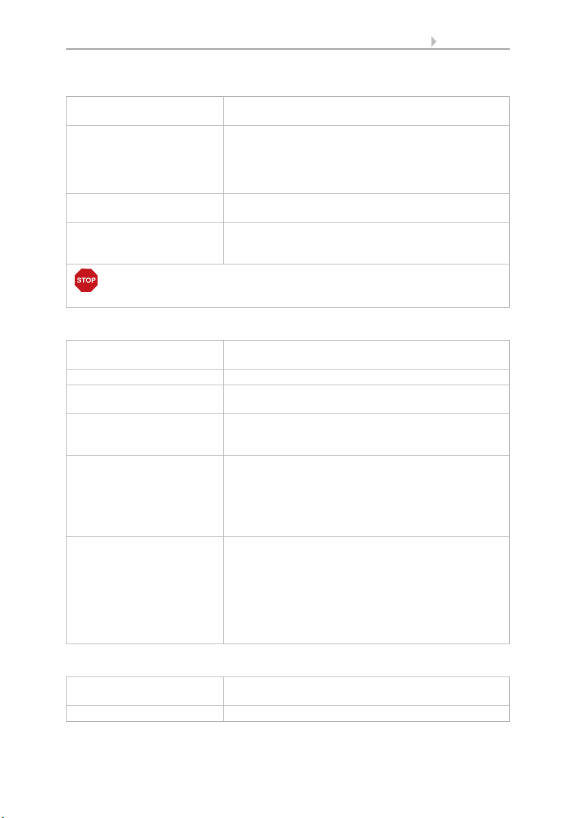
79 Basic setting
RF-B2-UP key interface:
Radio Module Type Display "RF-B2-UP"
Display serial number, version and RF router used
Key type channel 1/2 Shows how the channel is configured. Touch the field
and select:
• Double key
• 2x single keys with configuration each as change, on
or off key
Name Shows the name. Touch the field and enter the desired
name using the keyboard that appears.
Motor groups Touch the field to allocate motors and devices to the
key channels.
Touch the field to perform the allocation.
ATTENTION!
Only drives/devices that have the same function should be operated
together with one key (e.g. only blinds or only windows).
Roof ventilator WL400, WL800:
Radio Module Type Display "WL400/800"
Display serial number, version and RF router used
Radio Status Displays Radio Status
Name Shows the name. Touch the field and enter the desired
name using the keyboard that appears.
Manual menu Shows whether the radio participant is displayed in the
manual menu and in the start menu. Touch the field
and make your selection.
Adjust Shows the measured and displayed temperature value.
Touch the field to adjust the value displayed.
It may be necessary to correct the measured value if the
temperature at the sensor does not correspond to the
room average (e.g. if the sensor is installed above an
above-average warm location).
Safety contact Shows which safety contact the ventilator is assigned
to. Touch the field and select the desired multifunction
input configured as safety contact.
The contacts are connected to the MF inputs. If the
safety contact is open, exhaust/circulation air units are
switched off and manual operation is blocked. The
safety provisions for fireplaces dependent on room air,
for example, can be implemented with this.
WL-Z supply air unit:
Radio Module Type Display "WL-Z"
Display serial number, version and RF router used
Radio Status Displays Radio Status
WS1000 Connect controls • Version: 15.07.2019 • Technical changes and errors excepted.

80 Basic setting
Name Shows the name. Touch the field and enter the desired
name using the keyboard that appears.
Manual menu Shows whether the radio participant is displayed in the
manual menu and in the start menu. Touch the field
and make your selection.
Safety contact Shows which safety contact the ventilator is assigned
to. Touch the field and select the desired multifunction
input configured as safety contact.
The contacts are connected to the MF inputs. If the
safety contact is open, supply air units are opened and
manual operation is blocked. The safety provisions for
fireplaces dependent on room air, for example, can be
implemented with this.
RF-VM fan module:
Radio Module Type Display "RF-VM"
Display serial number, version and RF router used
Radio Status Displays Radio Status
Type of Automatic Shows the type of automatic controls. Touch the field
and select:
• Incoming air/exhaust air
• Fresh air/heat
Name Shows the name. Touch the field and enter the desired
name using the keyboard that appears.
Manual menu Shows whether the radio participant is displayed in the
manual menu and in the start menu. Touch the field
and make your selection.
Safety contact Shows which safety contact the ventilator is assigned
to. Touch the field and select the desired multifunction
input configured as safety contact.
The contacts are connected to the MF inputs. If the
safety contact is open, exhaust/circulation air units are
then switched off, supply air units are opened and manual operation is blocked. The safety provisions for fireplaces dependent on room air, for example, can be
implemented with this.
Relay RF-relay, RF-heating, Heatstrip radiator:
Radio Module Type Display "RF-Relay"
Display serial number, version and RF router used
Radio Status Displays Radio Status
WS1000 Connect controls • Version: 15.07.2019 • Technical changes and errors excepted.

81 Basic setting
Type of automatic controls
(only for RF relay)
Shows the type of automatic controls (connected to the
radio module). Touch the field and select:
• None
• Heating
• Air-conditioning unit
• Ventilation
• Light
• Gutter heating
• Alarm
• Dimmer.
If "Dimmer" or "None" is selected, the device can only
be operated manually, there are no automatic menus.
Name Shows the name. Touch the field and enter the desired
name using the keyboard that appears.
Manual menu Shows whether the radio participant is displayed in the
manual menu and in the start menu. Touch the field
and make your selection.
Motor control unit RF-MSG:
Radio Module Type Display "RF-MSG"
Display serial number, version and RF router used
Radio Status Displays Radio Status
Type of Automatic Shows what is connected to the radio module. Touch
the field and select:
• Reserve (unused)
• Awnings
• Windows
• Blinds
• Shutters
Name Shows the name. Touch the field and enter the desired
name using the keyboard that appears.
Manual menu Shows whether the radio participant is displayed in the
manual menu and in the start menu. Touch the field
and make your selection.
Other settings The other possible settings for the individual motor
types correspond to those for the cable-connected
motors
5.1.1. Set motors and motor groups, Page 71
Dimmer RF-L:
Radio Module Type Display "RF-dimmer"
Display serial number, version and RF router used
Radio Status Displays Radio Status
Name Shows the name. Touch the field and enter the desired
name using the keyboard that appears.
WS1000 Connect controls • Version: 15.07.2019 • Technical changes and errors excepted.

82 Basic setting
Manual menu Shows whether the radio participant is displayed in the
Min. dim value Shows the minimum dim value for manual dimming.
Max. dim value Shows the maximum dim value for manual dimming.
Switch-on behaviour Shows what happens when switching on Touch the
ON dim value (only if an ON
dim value is used when
switching on)
manual menu and in the start menu. Touch the field
and make your selection.
Touch the field and adjust the value using the slider.
For automatic mode, values can be set here that are
outside the set dimming range.
Touch the field and adjust the value using the slider.
For automatic mode, values can be set here that are
outside the set dimming range.
field and select a whether the
• On dim value
• Last value
should be dimmed when switching on.
You can define the ON dim value in the next setting.
Shows the dim value when switching on manually.
Touch the field to adjust the value using a slider.
RF-Router:
The RF router forwards the radio signal to other radio participants if the radio route is
to long for a direct connection.
Radio Module Type Display "RF-Router"
Radio Status Displays Radio Status
Name Shows the name. Touch the field and enter the desired
Router channels Touch the field to allocate a radio participant to each of
Display of serial number, version
name using the keyboard that appears.
the respective 16 router channels.
Touch a channel and select which radio participants
should be connected to the channel.
Delete:
Touch the field to delete the connection to the individual radio participants. All existing
radio modules are displayed. Touch a radio participant and confirm the deletion.
Radio activity in the 868.2 MHz band:
Shows the radio capacity utilisation The higher the percentage, the more radio traffic
on the band.
WS1000 Connect controls • Version: 15.07.2019 • Technical changes and errors excepted.

83 Basic setting
5.1.5. Allocate external keys
If external keys are installed locally for operating motors and devices, the settings and
allocations are made here. 10 connections are available for keys. Single keys (toggle
keys) or double keys (unlocked series keys) can be connected to these and configured.
System > Installation > Ext. keys
Select the keys used from the list on the right and set them one after the other. Until
the settings have been entered, the fields show Ext. keys 1...10. If a key has already
been configured, the function or name is displayed instead.
Type of key:
Shows the set key function. Touch the field and select:
• Reserve (unused)
• Change key (for single keys).
Switches with every press of the key. Dim by holding the key.
• Up/down key (for unlocked double keys).
For motor (shades, windows): Timer, i.e. short push of the button with dead
man principle, longer push of the button (> 1 second) with self-retention for
moving to the end position.
For switchable device (lighting, heating, etc.). Up key switches on, down key
off.
• OFF key
•ON key
Key direction (up/down keys):
Shows whether the key direction is normal or reversed. Touch the field to check the
direction and change it if necessary.
Press the up and down key of the button. The arrow shown in the display is activated.
If the direction of the key corresponds to the display, leave the setting Normal. Otherwise, press the key reversed. Now the key and display would have to agree.
Name:
Shows the name of the key. Touch the field and enter the desired name using the keyboard that appears.
Motor groups:
Shows which motors/devices are allocated to the key. Touch the field and select the
motor group or a device.
Only one device can be allocated to a single key (change/on/off), multiple motors or devices can be allocated to a double key (up/down).
WS1000 Connect controls • Version: 15.07.2019 • Technical changes and errors excepted.

84 Basic setting
ATTENTION
Only drives/devices that have the same function should be operated
together with one key (e.g. only blinds or only windows).
5.1.6. Allocate internal keys (group keys)
In manual mode, multiple motors or devices can be operated simultaneously via one
joint group key (internal software key). 20 internal keys are available.
System > Installation > Int. keys
Select the individual keys from the list on the right and set them one after the other.
The fields show Int. keys 1...20 until settings have been entered. If a key has already
been configured, the function or name is displayed instead.
Type of key:
Shows the set key function. Touch the field and select:
• Reserve (unused)
•Int. key
Name:
Shows the name of the key. Touch the field and enter the desired name using the keyboard that appears.
Manual menu:
Shows whether the group key is displayed in the manual menu and in the start menu.
Touch the field and make your selection.
The display on the start page is below the menu items "System" and "Manual menu".
The display sequence can be set in the menus
System > Installation > Start page or manual menu
5.1.8. Start page, Page 85
5.1.9. Manual page, Page 86
Motor groups:
Shows which motors/devices are allocated to the group key. Touch the field and select
the motor groups or a device.
ATTENTION
Only drives/devices that have the same function should be operated
together with one key (e.g. only blinds or only windows).
WS1000 Connect controls • Version: 15.07.2019 • Technical changes and errors excepted.

85 Basic setting
5.1.7. Scenes
In scenes, you define the status of various motors and devices so that they can then be
accessed with jut one push of a button. You can also specify, for example, that the light
should be dimmed and the shutters closed at the same time, and save this as "TV
evening" scene.
16 scenes are available in the WS1000 Connect controls.
System > Installation > Scenes
Select a scene from the list on the right and set it. The fields show Scene 1...16 until
settings have been entered. If a scene has already been configured, the name is displayed instead.
Name:
Shows the name of the scene. Touch the field and enter the desired name using the
keyboard that appears.
Manual menu:
Shows whether the scene is displayed in the manual menu and in the start menu.
Touch the field and make your selection. Default: Display in manual mode Yes, in start
menu No.
The display in the start menu is below the menu items "System" and "Manual menu".
The display sequence and other representation options can be set in the menus
System > Installation > Start page or manual menu
5.1.8. Start page, Page 85
5.1.9. Manual page, Page 86
Motor groups:
Shows which motors/devices are allocated to the scene. Touch the field and select the
motor groups or a device.
Touch each individual motor that should be included in the scene and set the movement position. Set the status for each device, e.g. On or Off.
5.1.8. Start page
Favourites and bookmarks are displayed on the left of the start page. You can set different display options here.
System > Installation > Start page
WS1000 Connect controls • Version: 15.07.2019 • Technical changes and errors excepted.

86 Basic setting
Display sequence:
Touch the field to specify the display sequence of the favourites and bookmarks. All entries are shown in a list. Hold an entry by the list symbol on the right and move it to the
desired position.
So that a motor is displayed as favourite, the setting "Start page" at the "Manual menu"
item has to be activated.
System > Installation > Motor/Multif.output > Manual menu
Bookmarks:
In the browser you can save websites as bookmarks.
Change name:
Touch the field to change the name of the bookmark. Select the bookmark from the list,
touch it and enter a name.
Delete bookmarks:
Touch the field to delete a bookmark. Select the bookmark from the list and confirm the
deletion.
5.1.9. Manual page
The menu item "Manual menu" is on the left side of the start page. This manual page
shows motors and devices for manual operation.
System > Installation > Manual page
So that a motor or device is displayed in the manual menu, the setting "Manual menu"
has to be activated in the installation settings.
System > Installation > Motor/Multif.output > Manual menu
Display sequence:
Touch the field to specify the display sequence in the manual menu. All entries are
shown in a list. Hold an entry by the list symbol on the right and move it to the desired
position.
Subject groups:
Touch the field to create subject groups.
As soon as a subject group has been activated, motors and
devices are no longer displayed in the manual menu!
All groups are shown in a list. Hold an entry by the list symbol on the right and move
it to the desired position.
WS1000 Connect controls • Version: 15.07.2019 • Technical changes and errors excepted.

87 Basic setting
Activate the groups you want to use by touching the check box. A pencil icon appears,
which touch to edit the group.
• All visible channels (no selections possible)
• Central function (scenes, group keys)
• Room controls (heating, air-conditioning)
• Floors (all functions)
• Output (motors, multifunction outputs, group keys)
• Input (sensors)
You can activate, sort and edit additional subgroups in each group.
Name:
Shows the name of the subgroup. Touch the field and enter the desired name using
the keyboard that appears.
Symbol:
Shows the selected symbol for the subgroup. Touch the field and select a symbol from
the list.
Allocate channels:
Touch the field and select the functions to be added to the group. Only the functions
that go with the subject are displayed for each group.
Display sequence:
Touch the field to specify the display sequence of the selected channels. All entries are
shown in a list. Hold an entry by the list symbol on the right and move it to the desired
position.
5.1.10.Weather data
The current data supplied by the weather station and indoor sensor is displayed on the
start page. The weather station's displayed temperature can be adjusted. If multiple indoor sensors are installed, select the sensor here, whose data should be displayed on
the start page.
System > Installation > Weather data
Weather station:
Touch the field to adjust the temperature value displayed. This adjusted value is also
used for the controls!
Weather display:
Shows which sensor is used for the weather data supply on the start page. If several
sensors are installed, touch the field to select the desired sensor.
WS1000 Connect controls • Version: 15.07.2019 • Technical changes and errors excepted.

5.2. Set up WS1000
System > Set up WS1000
88 Basic setting
You can make the following settings in the menu area System > Set up WS10000:
• Change individual data such as time/date and time and match the screen
display to your personal desires (settings)
• Restart the controls, reset to factory settings, change internal settings and start
remote maintenance (service)
• Set an access code to protect the menus "Installation" and "Set-up automatic"
against unauthorised change (access code)
• Save the setting details for the controls on SD card or read from SD card (SD
card)
• Set up the internet/network connection (internet)
• Load updates and check the software versions of the controls (device
information)
5.2.1. Settings
You can make the following settings in the menu area System > Set up WS10000 >
Settings:
• Time and date
WS1000 Connect controls • Version: 15.07.2019 • Technical changes and errors excepted.

89 Basic setting
• Language
•Display
• Key tone
•Time zone
•Location
Enter time and date manually
Date and time are displayed in the top right of the start page. Normally the data is received by the weather station via GPS. It is mostly received within approx. 10 minutes
of the system starting. If there is no time signal, set the click manually.
Time and date:
Shows the current time and date. Touch the field to enter the data manually.
Change language
The display can be set to German, English, French and Italian.
Language:
Shows the currently selected language. Touch the field to select a different language.
Set up screen
The WS1000 Connect can display picture file, time/temperature as a screen saver or
simple a black screen. The screen saver is activated if the display has not been touched
for 5 minutes.
Additionally, the display brightness can be adjusted automatically to the room brightness and the screen can switch off when dark.
Display:
Shows which screen saver is currently active and whether automatic brightness is
switched on. Touch the screen to see the menu.
Screen saver:
Select the screen saver:
• Without
• Black screen
• Time and temperature display
• Pictures from SD card. "Slide show" or "Single picture" can selected for the
picture display. The "Slide show" shows all pictures on the SD card one after
the other. With"Single picture", you can select the image from the SD card.
In order to show digital picture data as a slide show, save the files to a micro SD card.
The picture files must meet the following requirements:
WS1000 Connect controls • Version: 15.07.2019 • Technical changes and errors excepted.

90 Basic setting
• The files must be saved in the highest directory level of the card (master
directory
• File format: Bitmap (BMP, without RLE compression), Jpeg (JPG), GIF or PNG
(without transparency)
• For pictures with a page ratio other than 16:10, black bars are added at the top/
bottom or right/left. The display has a resolution of 1280 × 800 pixels
• Colour intensity 24 bit or 16 bit
The card socket is located on the right-hand side of the device. The SD card is pushed
into the slot, until it clicks into place. To remove, briefly press the card into the socket
so that is jumps out.
If picture data is saved on the card, the "Slide show" key is displayed on the right of the
upper menu bar, with which you can directly start it. The image changes approx. every
45 seconds (for images with 24-bit colour intensity). To interrupt the screen saver,
touch the screen or remove the SD card.
Automatic switch-off:
With the automatic switch-off, you set whether the display lighting should be switched
off when the room is dark. If no command is given for around 1 minute when it is dark,
the automatic switch-off darkens the screen again.
For the automatic switch-off, the central control unit of the WS1000 Connect con-
trols records the brightness. If it is bright in the room, the display lighting is automatically switched on. If the screen is touched, it also re-activates.
Automatic brightness:
The automatic brightness function adjusts the display screen to the light conditions in
the room (the darker the room, the darker the display screen lighting). Touching the
display screen increases the brightness by 30% in order to ensure excellent legibility.
If no instructions are entered for around 1 minute, the screen brightness is reduced
again.
If the automatic controls are off, the percentage screen brightness is set using a slider.
Switch key tone off/on
The key tone produced when a key is touched can be switched off and on again.
Key tone:
Shows whether the key tone is on or off. Touch the field to change the setting.
Select time zone
In order to be able to display the date and time, the time zone has to be set.
WS1000 Connect controls • Version: 15.07.2019 • Technical changes and errors excepted.

91 Basic setting
Time zone:
Shows the time zone currently set. Touch the field to change the setting.
The time zone can be entered "by location" or "user defined". Touch the field to switch
between the options.
When selecting by location, choose the city from the list provided. For user-defined setting, enter the time zone based on GMT (Greenwich Mean Time).
Enter location
The location is received by the weather station automatically by GPS. If there is no GPS
reception, set the location here.
The information on the location of the building is necessary in order to correctly indicate the position of the sun. If you do not provide this location data, the blinds will not
be correctly controlled.
Location:
Shows the current location. Touch the field and select the location as City or as coordinates (longitude and latitude).
5.2.2. Service settings
You can make the following settings in the menu area System > Set up WS10000 >
Service:
• Reset (restart)
• Factory settings
• Internal area
• Remote maintenance
ATTENTION
Damage due to incorrect use of the service functions!
The service settings are not needed in the normal function of the
controls.
Reset (restart)
Reset starts the control system software again. The automatic settings are retained. After starting, the motors and devices, for which an automatic reset is set, are in automatic mode.
Reset:
Touch the key to restart the controls.
WS1000 Connect controls • Version: 15.07.2019 • Technical changes and errors excepted.

92 Basic setting
Factory settings
ATTENTION
Damage due to incorrect use of the service functions!
The factory settings delete all settings made. There are
no longer any automatic controls.
All basic and automatic settings are deleted by resetting to factory settings. The control
system will be returned to its delivery condition.
Factory settings:
Touch the field if you want to reset the controls to the delivery status. Enter code "81"
and confirm. The factory settings are loaded and the controls restarted.
Internal area
The internal area is only needed by the manufacturer's service and offers the option to
change basic properties of the device.
Remote set up/remote maintenance
Access to the WS1000 Connect controls is possible via the internet using the remote maintenance function. An internet connection is needed for this. A service technician can then see and change the settings without being on site.
Network connection (internet)).
Access to the controls is only possible if remote maintenance is also started on the device. This is not a remote control option! If you want to operate the controls and your
building technology on the go, then use the WS1000 Connect App and set up a secure
VPN connection for your home network.
Remote maintenance:
The automatic screen switch-off is deactivated during remote maintenance. Activate it
again after the session, if required.
System > Set up WS1000 > Settings > Screen
Start remote maintenance software:
Touch the field to open the software. Follow the instructions. To create the connection,
the device ID of the WS1000 Connect must be input at the PC used for the remote
maintenance. Then every menu and function of the WS1000 Connect can be viewed
and controlled from the PC.
Close remote maintenance software:
Touch the field to end the remote maintenance session.
WS1000 Connect controls • Version: 15.07.2019 • Technical changes and errors excepted.

93 Basic setting
5.2.3. Access code
In the menu area System > Set up WS1000 > Access code you can set up access
codes in order to protect the controls from unauthorised access. The menus "Installation" and "Set-up automatic" can be protected as well as access by App.
Manual use of the controls remains free at all times.
Access to the menus of the central unit:
Enter code:
Touch the field and enter the desired access code. The code is shown unencrypted.
Confirm it. The controls now ask for this code before the menus "Installation" and "Setup automatic" are displayed.
Change code:
Touch the field and enter the existing code. Confirm, and enter the new access code.
The control system will ask for this new code before displaying the menus.
Delete code:
Touch the field and enter the existing code. Confirm it and the controls no longer have
an access code. If you have forgotten the current code, enter the unlock code "123" in
order to delete the code.
Access by App (via smartphone/tablet):
Shows whether an access code is needed for accessing the controls by App. Touch the
field and make your selection.
No, Do not allow access, prohibits any access by App to the controls.
Access without access code allows free access. The control functions can be used
with any smartphone, on which the App is installed and is connected to the same
WLAN.
Access with access code allows App operation of the controls only after a code has
been entered. Enter the desired PIN number.
WS1000 Connect controls • Version: 15.07.2019 • Technical changes and errors excepted.

94 Basic setting
The WS1000 Connect controls can load data from a micro SD card. The
SD card storage is needed for:
• Screen saver data
• Update files for software updates
• Saving settings (configuration file)
The card socket is located on the right-hand side of the device. The SD card
is pushed into the slot, until it clicks into place.
To remove, briefly press the card into the socket so that is jumps out.
5.2.4. Using an SD card
The card is automatically detected. If picture data is saved on the card, the "Slide show"
key is displayed on the right of the upper menu bar, with which you can directly start
it. The image changes approx. every 45 seconds (for images with 24-bit colour intensity). To interrupt the slide show, touch the screen or remove the SD card.
Information about possible picture information can be found in chapter Set up screen,
Page 89.
Save and load configuration data
The SD card can be used as a storage and transfer medium for set-up data to:
• Save the personal settings
• Save a summer and winter configuration
Load config.:
Touch the field in order to view all the configuration files in the card's master directory.
Touch an entry to load the file. The controls are restarted.
Save config.:
Touch the field in order to save the setting data for the controls on the SD card. Select
an existing configuration from the list in order to save it. Or add a new configuration
and enter the desired name it should be saved as.
Delete config.:
Touch the field in order to view all the configuration files in the card's master directory.
Touch an entry to delete the file (deletion must be confirmed).
WS1000 Connect controls • Version: 15.07.2019 • Technical changes and errors excepted.

95 Basic setting
Show pictures on the display
The WS1000 Connect can display digitally saved picture data as a slide show or a
single image. The picture data for this must be saved on an SD card.
Information about possible picture information can be found in chapter Set up screen,
Page 89.
The sequence of the catalogue of individual images and of the slide show corresponds
to the sequence in which the images were saved onto the card. The images are not
sorted according to name.
To return to the start page, touch the screen or remove the SD card.
Slide show:
Touch the field to start the slide show. The images are displayed in the same sequence
as they were saved onto the card (see note below). The image changes approx. every
45 seconds (for images with 24-bit colour intensity).
Single picture:
Touch the field if you want to display a single picture. All pictures saved on the card
are displayed. Select the desired picture.
Internet
The WS1000 Connect controls is internet-ready and can be connected to a network
by cable (Ethernet/LAN) or WiFi (WLAN). The network connection is needed for:
• Use of Apps (with smartphones and tablets in the same network/WLAN)
If the WS1000 Connect is also connected to the internet via the internal network, the
following functions are also possible:
• Accessing web contents in the controls' browser (also e.g. streaming)
• Remote access (e.g. for system set-up, diagnosis)
The Ethernet/LAN connection terminal can be accessed after removing the display,
without having to remove the touch protection (cover for 230 V power area). Note the
information regarding assembly.
Connection status:
Shows the current status (disconnected or connected).
Connection type:
Shows the type of connection (Ethernet or WLAN). Touch the field to set up the connection.
WLAN: Wireless connection. If WLAN has been confirmed, the additional field "Network name" is displayed for the additional set up.
WS1000 Connect controls • Version: 15.07.2019 • Technical changes and errors excepted.

96 Basic setting
Ethernet: Cable connection via the LAN socket on the circuit board. No other settings
necessary.
Network name (SSID):
The network is selected and set up here under the setting WLAN. Enter a network name
or touch "Find networks" to view all available networks.
Create connection:
You can only "Create connection" using this touch field once a network has been selected. The password for the network is requested.
If necessary, use the same field to terminate the connection.
Protect your network with the latest encryption technology and
change your passwords regularly!
Device information
The software for the WS1000 Connect controls can be updated during normal operation. If the control is connected to the internet, the control downloads updates automatically after confirmation. Alternatively, you load the new software from the Elsner Elektronik website and save it to the SD card. After inserting the SD card into the
socket on the WS1000 Connect, continue.
Check for updates:
Shows the currently installed version and facilitates the installation of SD card or the
search for updates on the internet. Follow the download and installation instructions
on the display.
WS1000 Connect, display, connection boards, Elsner radio:
The current versions of the device are displayed.
WS1000 Connect controls • Version: 15.07.2019 • Technical changes and errors excepted.

97 Tables, plans, maintenance
6. Tables, plans, maintenance
WS1000 Connect controls • Version: 15.07.2019 • Technical changes and errors excepted.
98 Tables, plans, maintenance
6.1. Maintenance and care
Maintenance of the weather station
WARNING!
Risk of injury caused by components moved automatically!
The automatic control can start system components and place people in
danger (e.g. moving windows/awnings if a rain/wind alarm has been
triggered while cleaning).
• Always isolate the device from the mains for servicing and cleaning.
The device must regularly be checked for dirt twice a year and cleaned if necessary. In
case of severe dirt, the sensor may not work properly anymore.
ATTENTION
The device can be damaged if water penetrates the housing.
• Do not clean with high pressure cleaners or steam jets.
Maintenance of the controls
Remove fingerprints from the touchscreen ideally using a wet cloth or a microfibre
cloth. You can wipe over the keys without activating them.
Do not use foaming or cleaning agents or aggressive care materials when cleaning.
If there is a power outage, the data entered by you is saved for approx. 10 years. A battery is not needed for this. After the mains power has been restored, the clock is set
automatically as soon as the weather station receives a time signal.
6.1.1. Units for sun and wind
The display of sun intensity is in lux or kilolux and is shortened in the display to lx or
klx. The value 1 is reached even with overcast skies, 20 klx if the sun has just come out
again and 100 klx is reached when there are cloudless skies at noon. Experience indicates that extending shades above 40 klx is to be recommended.
The display of wind speed is in meters per second and is shortened in the display to
m/s. Depending on the position of the building and the installation position of the
weather station, different values may be optimal in order to protect the shade or window. Observe the response of the awning or blinds or the window to wind and then
correct the wind value accordingly.
The following table should make it easier to find the optimal values for your situation:
WS1000 Connect controls • Version: 15.07.2019 • Technical changes and errors excepted.
 Loading...