

Elsner Suntracer KNX-GPS light Technical Specifications And Installation Instructions
EN
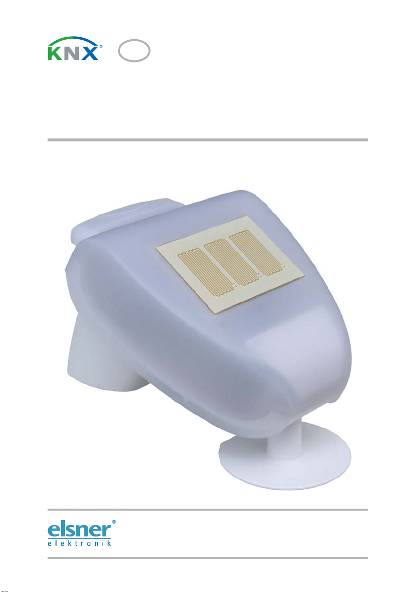
Suntracer KNX-GPS light
Weat her Station
Technical specifications and installation instructions
Elsner Elektronik GmbH Control and Automation Engineering
Herdweg 7
D – 75391 Gechingen Phone +49 (0) 70 56 / 93 97-0 info@elsner-elektronik.de
Germany Fax +49 (0) 70 56 / 93 97-20 www.elsner-elektronik.de
2 Description
1. Description
The Weather Station Suntracer KNX-GPS light light measures temperature, wind
speed and brightness. It perceives precipitation and receives the GPS signal for time
and position. Furthermore, the exact position of the sun (azimuth and elevation) is calculated on the basis of location coordinates and time.
ATTENTION
The calculation of the position of the sun is optimised for UTC -1...+3.
The device therefore may only be applied within Europe. For other time
zones, please use Suntracer KNX-GPS Weather Station.
All data may be used for the control of switching outputs which depend on threshold
values. The states may be linked by means of AND and OR logic gates. The compact
housing of Suntracer KNX-GPS light stores the sensor system, the evaluation electronics and the electronics of the bus connection.
Functions:
• Brightness and position of the sun: The current light intensity is measured
by means of a sensor. At the same time, Suntracer KNX-GPS light calculates
the position of the sun (azimuth and elevation) on the basis of time and location
• Wind measurement: The measurement of wind speed is accomplished
electronically and thus noiseless and reliable even in case of hail, snow and
minus temperature. Air swirls and up-draught in the radius of the weather
station are collected, too
• Precipitation perception: The surface of the sensor is heated so that only
drops and flakes are recognised as precipitation but not fog or dew. If it stops
raining or snowing, the sensor dries quickly and the precipitation message
ends
• Temperature measurement
• Week and calendar time switch: The weather station receives time and date
from the integrated GPS receiver. The week time switch operates up to 4
different periods each day. With the calendar time switch, you may determine
3 additional periods where the time switch accomplishes up to 2 activations
and deactivations each day. The Switching outputs can be used as
communication objects. The switching times are set by parameter or via
communication objects
• Switching outputs for all measured and calculated values (Threshold values
can be set by parameter or via communication objects)
• 8 AND and 8 OR logic gates with each 4 inputs. Every switching incident as
well as 8 logic inputs (in the form of communication objects) may be used as
inputs for the logic gates. The output of each gate may optionally be configured
as 1 bit or 2 x 8 bits
Configuration is made using the KNX software ETS. The programme file (format VD),
the data sheet and the manual can be downloaded from the Elsner Elektronik
homepage on www.elsner-elektronik.de in the “Service” menu.
Weather Station Suntracer KNX-GPS light • Version: 15.07.2013 • Technical changes reserved. Errors reserved.

3 Description
1.1. Technical specifications
Housing Plastic material
Colour White / translucent
Mounting On-wall
Protection category IP 44
Dimensions approx. 96 × 77 × 118 (W × H × D, mm)
Weight approx. 170 g
Ambient temperature Operation -30…+50°C, Storage -30…+70°C
Operating voltage 12…40 V DC (12…28 V AC)
Auxiliary current max. 185 mA at 12 V DC
Bus current max. 8 mA
Data output KNX +/- bus terminal plug
BCU type Own micro controller
PEI type 0
Group addresses max. 254
Allocations max. 255
Communication objects 222
Heating rain sensor approx. 1.2 W (230 V and 24 V)
Measurement range
temperature:
Resolution (temperature) 0.1°C
Accuracy (temperature) ±1°C at -10…+85°C
Measurement range wind 0…35 m/s
Resolution (wind) 0,1 m/s
Accuracy (wind) at ambient temperature -20…+50°C:
Measurement range
brightness
Resolution (brightness) 1 lux at 0…120 lux
Accuracy (brightness) ±35%
max. 81 mA at 24 V DC
Residual ripple 10%
-40…+80°C
±1.5°C at -25…+150°C
±22% of the measurement value when incident flow is
from 45…315°
±15% of the measurement value when incident flow is
from 90…270°
(Frontal incident flow corresponds to 180°)
0…150 000 lux
2 lux at 121…1 046 lux
63 lux at 1 047…52 363 lux
423 lux at 52 364…150 000 lux
The product conforms with the provisions of EC guidelines
• EMC Directive 2004/108/EC
Weather Station Suntracer KNX-GPS light • Version: 15.07.2013 • Technical changes reserved. Errors reserved.

4 Installation and commissioning
• Low Voltage Directive 2006/95/EC
The following standards and/or technical specifications have been applied:
• EN 50491-5-1: 2010
• EN 50491-5-2: 2011
2. Installation and commissioning
2.1. Installation notes
Installation, testing, operational start-up and troubleshooting should
only be performed by an electrician.
CAUTION!
Live voltage!
There are unprotected live components inside the device.
• National legal regulations are to be followed.
• Ensure that all lines to be assembled are free of voltage and take
precautions against accidental switching on.
• Do not use the device if it is damaged.
• Take the device or system out of service and secure it against
unintentional use, if it can be assumed, that risk-free operation is no
longer guaranteed.
The device is only to be used for its intended purpose. Any improper modification or
failure to follow the operating instructions voids any and all warranty and guarantee
claims.
After unpacking the device, check it immediately for possible mechanical damage. If it
has been damaged in transport, inform the supplier immediately.
The device may only be used as a fixed-site installation; that means only when assembled and after conclusion of all installation and operational start-up tasks and only in
the surroundings designated for it.
Elsner Elektronik is not liable for any changes in norms and standards which may occur
after publication of these operating instructions.
2.1.1. Installation position
Choose an installation position in the building where wind, rain and sun can be measured unhindered by the sensors. The weather station must not be installed underneath
any structural parts from which water can still drip onto the rain sensor after it has
stopped raining or snowing. The weather station must not be shaded by anything,
such as building structures or trees. There must be at least 60 cm of free space underneath the weather station to allow it to measure the wind correctly and to prevent it
from being snowed in when it snows. The distance also protects the unit against damage by birds.
Weather Station Suntracer KNX-GPS light • Version: 15.07.2013 • Technical changes reserved. Errors reserved.
 Loading...