

Elsner Suntracer KNX basic Installation And Adjustment
Suntracer KNX basic
Weather Station
Item numbers 3095 (230V), 3096 (12...40 V DC, 12...28 V AC)
EN
Installation and Adjustment


1 Contents
Elsner Elektronik GmbH • Sohlengrund 16 • 75395 Ostelsheim • Germany
Weather Station Suntracer KNX basic • from software version 1.06, ETS programme version 1.1
Version: 25.06.2018. Technical changes and errors excepted.
1. Description ........................................................................................... 3
1.1. Technical specifications ........................................................................................... 3
2. Installation and commissioning ........................................................... 4
2.1. Installation notes ...................................................................................................... 4
2.1.1. Location ......................................................................................................... 5
2.2. Mounting the weather station ................................................................................. 6
2.2.1. Attaching the mount ..................................................................................... 6
2.2.2. View of rear side and drill hole plan ........................................................... 8
2.2.3. Weather station layout ................................................................................. 9
2.2.4. Connection of the weather station .............................................................. 9
2.2.5. PCB layout ................................................................................................... 10
2.2.6. Mounting the weather station ................................................................... 11
2.3. Notes on mounting and commissioning .............................................................. 12
3. Addressing of the device at the bus .................................................. 13
4. Maintenance ....................................................................................... 13
5. Transmission protocol ....................................................................... 14
5.1. List of all communication objects ......................................................................... 14
6. Setting of parameters ........................................................................ 18
6.1. General settings ..................................................................................................... 18
6.2. Temperature ........................................................................................................... 19
6.2.1. Temperature threshold value 1 / 2 / 3 / 4 .................................................. 19
6.3. Wind force ............................................................................................................... 20
6.3.1. Wind threshold value 1 / 2 / 3 .................................................................... 20
6.4. Brightness ............................................................................................................... 22
6.4.1. Brightness threshold value 1 / 2 / 3 ........................................................... 22
6.5. Dawn ....................................................................................................................... 22
6.5.1. Dawn threshold value 1 / 2 / 3 .................................................................... 22
6.6. AND Logic ............................................................................................................... 22
6.6.1. AND Logic 1 / 2 / 3 / 4 / 5 / 6 / 7 / 8 .............................................................. 22
6.6.2. Linkage inputs of AND logic ...................................................................... 23
6.7. OR Logic .................................................................................................................. 24
6.7.1. OR Logic 1 / 2 / 3 / 4 / 5 / 6 / 7 / 8 ................................................................ 24
6.7.2. Linkage inputs of OR logic ......................................................................... 25

2 Clarification of signs
This manual is amended periodically and will be brought into line with new software
releases. The change status (software version and date) can be found in the contents footer.
If you have a device with a later software version, please check
www.elsner-elektronik.de in the menu area "Service" to find out whether a more up-todate version of the manual is available.
Clarification of signs used in this manual
Installation, inspection, commissioning and troubleshooting of the device
must only be carried out by a competent electrician.
Safety advice.
Safety advice for working on electrical connections, components,
etc.
DANGER!
... indicates an immediately hazardous situation which will lead to
death or severe injuries if it is not avoided.
WARNING!
... indicates a potentially hazardous situation which may lead to
death or severe injuries if it is not avoided.
CAUTION!
... indicates a potentially hazardous situation which may lead to
trivial or minor injuries if it is not avoided.
ATTENTION!
... indicates a situation which may lead to damage to property if it is
not avoided.
ETS In the ETS tables, the parameter default settings are marked by
underlining.
3 Description
Weather Station Suntracer KNX basic • Version: 25.06.2018 • Technical changes and errors excepted.
1. Description
The Weather Station Suntracer KNX basic perceives temperature, wind speed,
brightness and precipitation. All data may be used for the control of switching outputs
which depend on threshold values. The states may be linked by means of AND and OR
logic gates. The compact housing of Suntracer KNX basic stores the sensor system,
the evaluation electronics and the electronics of the bus connection.
Functions:
• Brightness measurement: The current light intensity is measured by means
of a sensor
• Wind measurement: The measurement of wind speed is accomplished
electronically and thus noiseless and reliable even in case of hail, snow and
minus temperature. Air swirls and up-draught in the radius of the weather
station are collected, too
• Precipitation perception: The surface of the sensor is heated so that only
drops and flakes are recognised as precipitation but not fog or dew. If it stops
raining or snowing, the sensor dries quickly and the precipitation message
ends
• Temperature measurement
• Threshold values can be adjusted per parameter or via communication
objects
• 8 AND and 8 OR logic gates with each 4 inputs. Every switching incident as
well as 8 logic inputs (in the form of communication objects) may be used as
inputs for the logic gates. The output of each gate may optionally be configured
as 1 bit or 2 x 8 bits
Configuration is made using the KNX software ETS. The product file can be downloaded from the Elsner Elektronik website on www.elsner-elektronik.de in the “Service” menu.
1.1. Technical specifications
Housing Plastic material
Colour White / translucent
Mounting On-wall
Protection category IP 44
Dimensions approx. 96 × 77 × 118 (W × H × D, mm)
Weight 230 V AC version: approx. 240 g
12...40 V DC, 12...28 V AC version: approx. 170g
An appropriate power supply unit can be obtained from
Elsner Elektronik.
Ambient temperature Operation -30…+50°C, Storage -30…+70°C
Operating voltage Available for 230 V AC or for 12...40 V DC, 12...28 V AC
Current 230 V AC version: max. 20 mA
12...40 V DC, 12...28 V AC version: max. 100 mA
Residual ripple 10%
4 Installation and commissioning
Weather Station Suntracer KNX basic • Version: 25.06.2018 • Technical changes and errors excepted.
The product conforms with the provisions of EU directives.
2. Installation and commissioning
2.1. Installation notes
Installation, testing, operational start-up and troubleshooting should
only be performed by an electrician.
DANGER!
Risk to life from live voltage (mains voltage)!
There are unprotected live components within the device.
• VDE regulations and national regulations are to be followed.
• Ensure that all lines to be assembled are free of voltage and take
precautions against accidental switching on.
• Do not use the device if it is damaged.
• Take the device or system out of service and secure it against
unintentional use, if it can be assumed, that risk-free operation is no
longer guaranteed.
Data output KNX +/- bus terminal plug
BCU type Own micro controller
PEI type 0
Group addresses max. 254
Allocations max. 255
Communication objects 109
Heating rain sensor approx. 1.2 W
Measurement range
temperature
-40…+80°C
Resolution (temperature) 0.1°C
Accuracy (temperature) ±1°C at -10…+85°C
±1.5°C at -25…+150°C
Measurement range wind 0…70 m/s
Resolution (wind) <10% of the measured value
Accuracy (wind) ±25% at 0…15 m/s
at an angle of attack of 45°, pole mounting
Measurement range
brightness
0…150 000 lux
Resolution (brightness) 1 lux at 0…120 lux
2 lux at 121…1 046 lux
63 lux at 1 047…52 363 lux
423 lux at 52 364…150 000 lux
Accuracy (brightness) ±35%
5 Installation and commissioning
Weather Station Suntracer KNX basic • Version: 25.06.2018 • Technical changes and errors excepted.
The device is only to be used for its intended purpose. Any improper modification or
failure to follow the operating instructions voids any and all warranty and guarantee
claims.
After unpacking the device, check it immediately for possible mechanical damage. If it
has been damaged in transport, inform the supplier immediately.
The device may only be used as a fixed-site installation; that means only when assembled and after conclusion of all installation and operational start-up tasks and only in
the surroundings designated for it.
Elsner Elektronik is not liable for any changes in norms and standards which may occur
after publication of these operating instructions.
2.1.1. Location
Select an assembly location at the building where wind, rain and sun may be collected
by the sensors unobstructedly. Do not assemble any construction components above
the weather station from where water may drop on to the rain sensor after it has
stopped raining or snowing. The weather station may not be shaded by the building or
for example by trees.
At least 60 cm of clearance must be left all round the weather station. This facilitates
correct wind speed measurement without eddies. The distance concurrently prevents
spray (raindrops hitting the device) or snow (snow penetration) from impairing the
measurement. It also does not allow birds to bite it. Please ensure that the extended
awning does not cast shade on the unit, and that this is not protected from the wind.
Temperature measurements can also be affected by external influences such as by
warming or cooling of the building structure on which the sensor is mounted, (sunlight, heating or cold water pipes). Temperature variations from such sources of interference must be corrected in the ETS in order to ensure the specified accuracy of the
sensor (temperature offset).
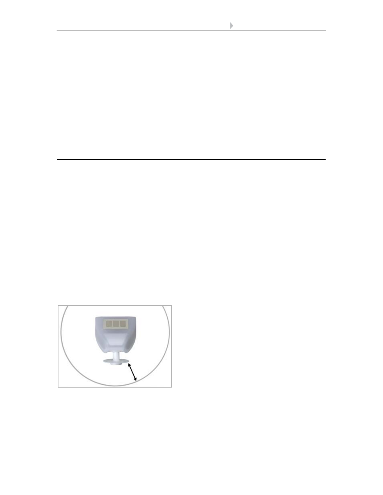
Fig. 1
There must be at least 60 cm of space below,
to the sides and in front of the weather station
left from other elements (structures, construction parts, etc.).
60 cm
6 Installation and commissioning
Weather Station Suntracer KNX basic • Version: 25.06.2018 • Technical changes and errors excepted.
2.2. Mounting the weather station
2.2.1. Attaching the mount
The sensor comes with a combination wall/pole mount. The mount comes adhered by
adhesive strips to the rear side of the housing. Fasten the mount vertically onto the wall
or pole.
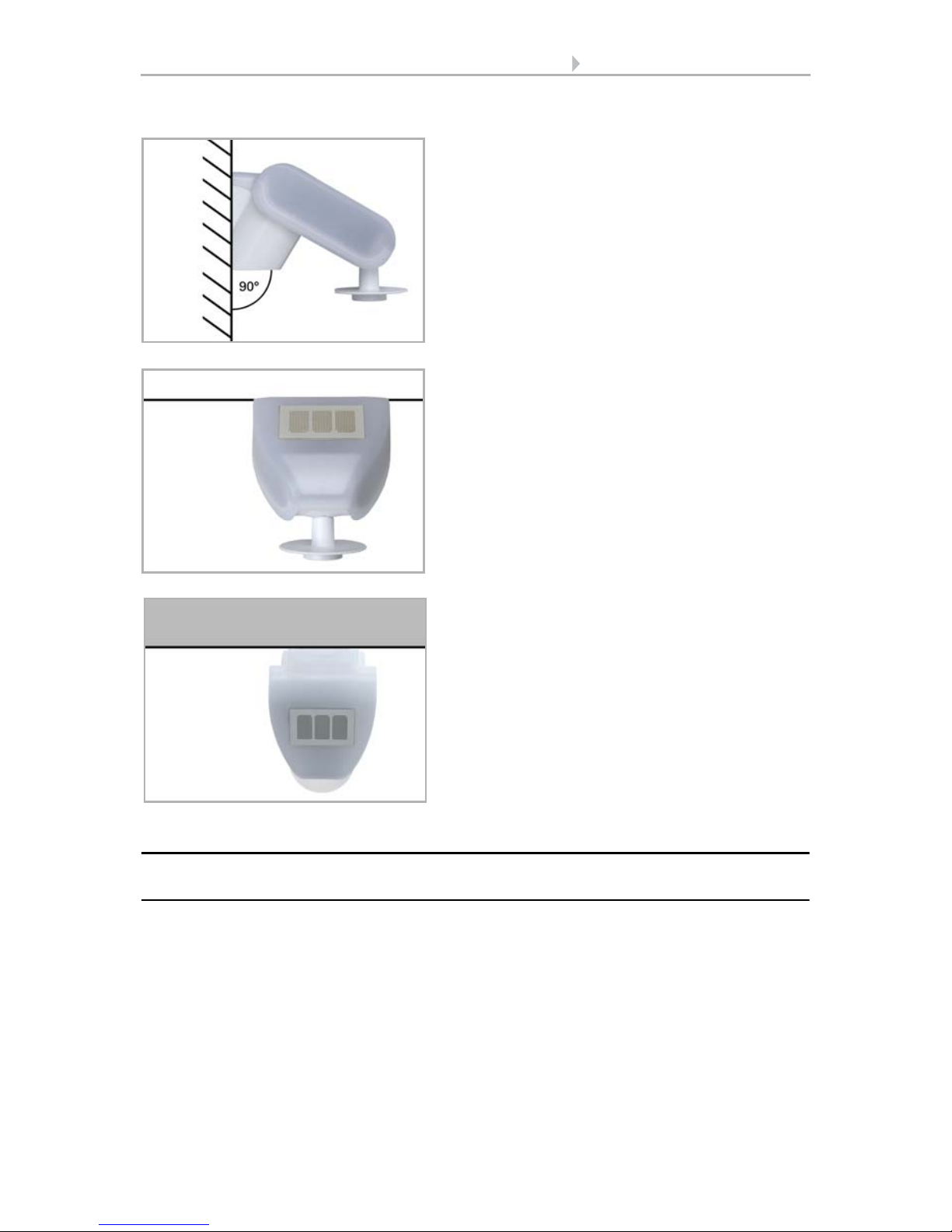
Fig. 2
The wind sensor must be mounted onto a
vertical wall (or pole).
Wall
or
pole
Fig. 3
The wind sensor must be mounted horizontally in the lateral direction.
Horizontal
Fig. 4
The weather station must be aligned in the
direction of the façade on which shade is to
be provided.
Facade
7 Installation and commissioning
Weather Station Suntracer KNX basic • Version: 25.06.2018 • Technical changes and errors excepted.
Fig. 5
When wall mounting: flat side on wall, crescentshaped collar upward.
Collar
Fig. 6
When pole mounting: curved side on pole, collar
downward.
Collar
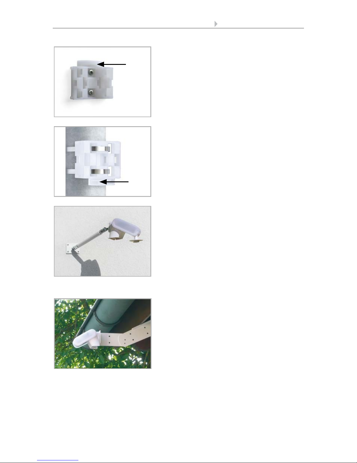
Fig. 7
Different mounting arms are available from Elsner Elektronik as additional, optional accessories
for flexible installation of the weather station on
a wall, pole or beam (pictures of sensors exemplary).
Example of the use of a mounting arm: Due to
flexible ball joints, the sensor can be brought
into ideal position.
Fig. 8
Example use of the hinge arm mounting:
With the hinge arm mounting, the weather station projects from beneath the roof overhang.
Sun, wind and precipitation can act upon the
sensors without hindrance.
 Loading...