

Elsner Remo KNX RF Installation And Adjustment
Remo KNX
Remote Control
Item number 70747
EN
Installation and Adjustment

1 Content
Elsner Elektronik GmbH • Sohlengrund 16 • 75395 Ostelsheim • Germany
Radio remote control Remo KNX RF • from software version 1.3, ETS programme version 2.0
Status: 15.01.2019 • Technical changes and errors excepted.
1. Description ........................................................................................... 5
1.1. Deliverables .............................................................................................................. 6
1.2. Technical specifications ........................................................................................... 6
1.3. Notes on wireless equipment ................................................................................. 6
2. First use/set-up ..................................................................................... 7
2.1. Loading the battery, transport block ...................................................................... 7
2.2. Protective film ........................................................................................................... 7
2.3. Set-up procedure ...................................................................................................... 7
3. Using the remote control ..................................................................... 8
3.1. Automatic switch-off ................................................................................................ 8
3.2. Display ....................................................................................................................... 8
3.3. Operating drives and devices .................................................................................. 8
3.3.1. Control media ................................................................................................ 8
3.3.2. Moving drives (Up/Down) ............................................................................ 9
3.3.2.1. Buttons: ......................................................................................... 10
3.3.2.2. Sliders: ........................................................................................... 10
3.3.3. Switching devices (on/off) .......................................................................... 10
3.3.4. Dimming ...................................................................................................... 11
3.3.4.1. Buttons: ......................................................................................... 11
3.3.4.2. Sliders: ........................................................................................... 11
3.3.5. RGB(W) lights .............................................................................................. 11
3.3.5.1. On/off buttons: .............................................................................. 12
3.3.5.2. Sliders: ........................................................................................... 12
3.3.6. Lights with adjustable colour temperature ............................................... 13
3.3.6.1. Buttons: ......................................................................................... 13
3.3.6.2. Sliders: ........................................................................................... 13
3.3.7. Changing temperature ............................................................................... 13
3.3.7.1. Buttons: ......................................................................................... 14
3.3.7.2. Sliders: ........................................................................................... 14
3.3.8. Scenes ......................................................................................................... 14
3.3.9. Measured value view .................................................................................. 14
4. Care and maintenance ....................................................................... 15
4.1. Troubleshooting ..................................................................................................... 15
5. Channel setting in the ETS ................................................................. 16
5.1. Transfer protocol .................................................................................................... 16
5.2. System .................................................................................................................... 18
5.3. Media page ............................................................................................................. 18
5.4. Channel activation .................................................................................................. 20
5.5. Channel 1...8 ........................................................................................................... 20
5.5.0.1. Display type: .................................................................................. 21
5.5.0.2. Input type – Switching: ................................................................. 21
5.5.0.3. Input type – Dimming: .................................................................. 22
2 Content
Elsner Elektronik GmbH • Sohlengrund 16 • 75395 Ostelsheim • Germany
Radio remote control Remo KNX RF • from software version 1.3, ETS programme version 2.0
Status: 15.01.2019 • Technical changes and errors excepted.
5.5.0.4. Input type – RGB/RGBW: .............................................................. 22
5.5.0.5. Input type – Colour temperature: ................................................ 23
5.5.0.6. Input type – Shutter: ..................................................................... 24
5.5.0.7. Input type – Blinds, awnings: ....................................................... 25
5.5.0.8. Input type – Window: ................................................................... 26
5.5.0.9. Input type – Temperature: ............................................................ 26
5.5.0.10.Input type – Scene: ....................................................................... 27
5.5.1. Control modes for drive control ................................................................ 28
6. Remote control programming ............................................................ 29
7. Remote control set-up ........................................................................ 30
7.1. Display ..................................................................................................................... 30
7.2. Wireless channel configuration ............................................................................ 31
7.2.1. Changing channel name ............................................................................ 31
7.2.2. Text for feedback ........................................................................................ 32
7.2.3. Text for on/off .............................................................................................. 33
7.2.4. Changing channel order ............................................................................. 34
7.3. System .................................................................................................................... 34

3 Clarification of signs
This manual is amended periodically and will be brought into line with new software
releases. The change status (software version and date) can be found in the contents footer.
If you have a device with a later software version, please check
www.elsner-elektronik.de in the menu area "Service" to find out whether a more up-todate version of the manual is available.
Clarification of signs used in this manual
Installation, inspection, commissioning and troubleshooting of the device
must only be carried out by a competent electrician.
Safety advice.
Safety advice for working on electrical connections, components,
etc.
DANGER!
... indicates an immediately hazardous situation which will lead to
death or severe injuries if it is not avoided.
WARNING!
... indicates a potentially hazardous situation which may lead to
death or severe injuries if it is not avoided.
CAUTION!
... indicates a potentially hazardous situation which may lead to
trivial or minor injuries if it is not avoided.
ATTENTION!
... indicates a situation which may lead to damage to property if it is
not avoided.
ETS In the ETS tables, the parameter default settings are marked by
underlining.
4 Clarification of signs
5 Description
Remote Control Remo KNX RF • Version: 15.01.2019 • Technical changes and errors excepted.
1. Description
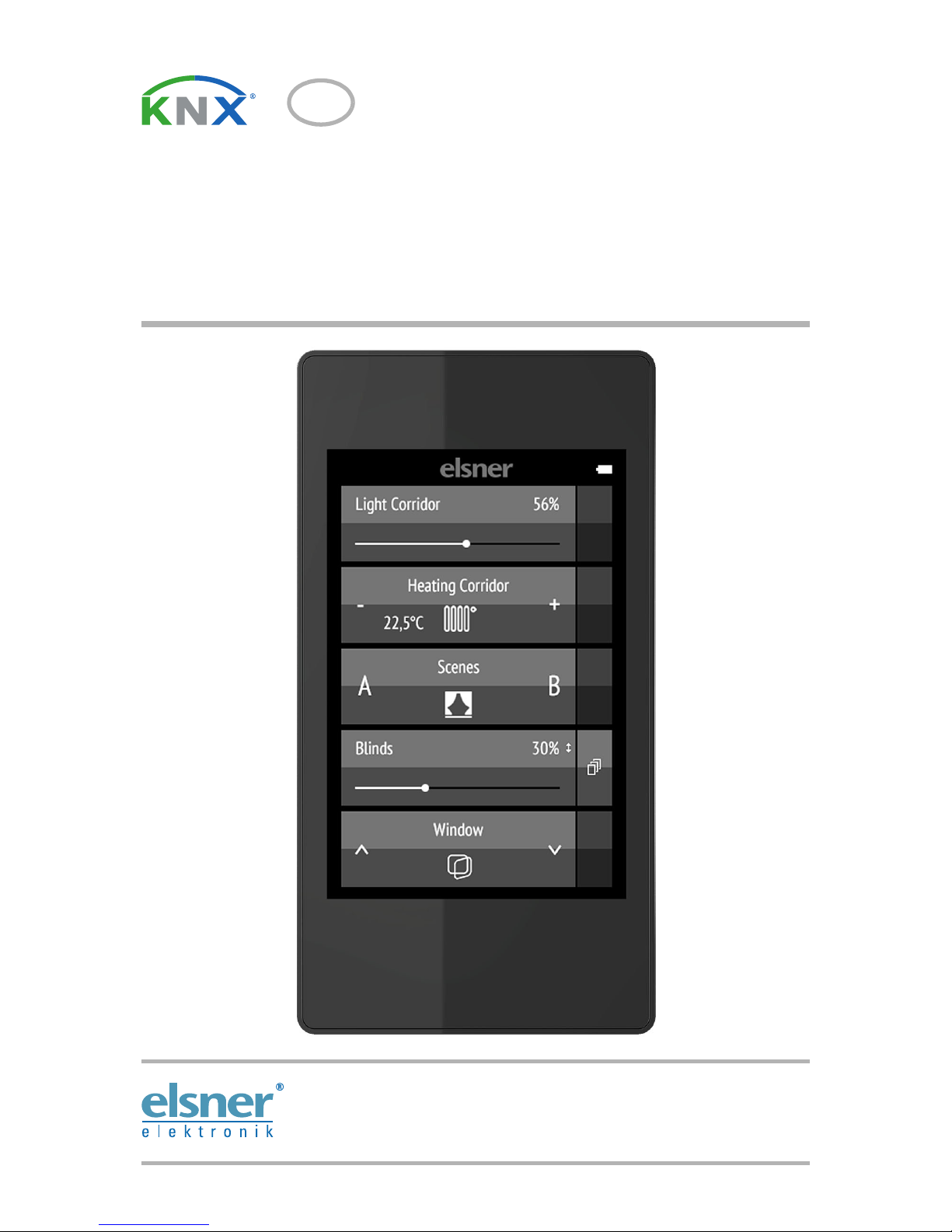
The colour touchscreen of Remote Control Remo KNX RF can be used to manually to
control bus participants in the KNX system. Remo KNX RF uses the KNX RF S standard.
The possible functions are
•Switch
•Dimm
• Move the drives of awnings, shutters, blinds or windows
• Change the temperature (for heating/cooling)
• Change RGBW light colour
• Change light colour temperature
• Call and save scenes
• Operate media equipment
• Indicate bus values (e.g. status, sensor values).
The channels are set in the ETS. However, they can be individually sorted and named on
the display.
Functions:
• Operation via the touch display
• Lithium battery, chargeable via a USB-2.0 Micro-B charger (Charger No 10155 as an
optional accessory). Battery level status and a warning at <20% battery charge can
be sent via the bus
• 32 channels, wireless standard KNX RF, S-Mode
• The touch buttons can be named individually, directly on the device or in the ETS
• The display sequence can be changed directly on the device
• Setting functions on the display can be locked (and unlocked) via the application
and the bus
Configuration is made using the KNX software ETS 5. The product file can be downloaded
from the ETS online catalogue and the Elsner Elektronik website on www.elsner-elektro-
nik.de in the “Service” menu.
If communication with wired KNX devices (KNX TP) is necessary, a media coupler that connects KNX RF and KNX TP is needed (e.g. KNX RF LC-TP No 70710).
ATTENTION!
Radio transmission takes place on a non-exclusive transmission
path!
The device is not suitable for applications in the field of safety engineering, e.g.
emergency stop, emergency call.
Moisture is harmful to the electronic components of the remote
control. You must therefore:
• Not leave it in the rain
• Not leave it outside overnight
• Protect it from frost
6 Description
Remote Control Remo KNX RF • Version: 15.01.2019 • Technical changes and errors excepted.
1.1. Deliverables
• Wireless remote control with integrated battery
• USB cable 0.5 m (USB-A plug to USB-B micro plug)
1.2. Technical specifications
The product is compliant with the provisions of EC guidelines.
1.3. Notes on wireless equipment
When planning facilities with devices that communicate via radio, adequate radio reception
must be guaranteed. The range will be limited by legal regulation and structural circumstances. Avoid sources of interference and obstacles between receiver and transmitter, that
could disturb the wireless communication. Those would be for example:
• Walls and ceilings (especially concrete and solar protection glazing).
• Metal surfaces next to the wireless participants (e. g. aluminium construction of a
conservatory).
• Other wireless devices and powerful local transmitters (e.g. wireless headphones),
which transmit on the same frequency. Please maintain a minimum distance of 30
cm between wireless transmitters for that reason.
Housing Plastic
Colour black
Protection category IP 40
Dimensions approx. 64 x 122 x 11 (B x H x T, mm)
Display colour TFT, capacitive, dimmable,
resolution 320 x 480 Pixel
Weight approx. 100 g
Ambient temperature operating 0…50 °C, storage -10…+60 °C
Ambient humidity max. 95 % RH, avoid condensation
Operating voltage integrated battery 3.8 V DC
Wireless frequency 868.2 MHz
Channels 32
Data output KNX RF (S-Mode)
BCU Type own micro controller
PEI Type 0
Group addresses max. 512
Assignments max. 1024
Communication objects 417
7 First use/set-up
Remote Control Remo KNX RF • Version: 15.01.2019 • Technical changes and errors excepted.
2. First use/set-up
2.1. Loading the battery, transport block
First, charge the integrated battery of the remote control with a standard commercial USB
charging device (USB 2.0 Micro B connector). Charging will reset the transport block that is
active on delivery. The remote control can be used only once it is connected to the power
supply via the charging cable.
If necessary, the transport block can be reactivated within the System menu (see manual,
chapter System).
The charge level of the battery and a warning if the level is under 20% can be sent via the
bus. Battery charge level and low-battery warning (bus notification). See manual, System
chapter.
The battery of the device cannot be removed or replaced. When disposing of the device,
observe the guidelines for disposing of devices with an integrated battery.
2.2. Protective film
Remove the protective film from the display.
2.3. Set-up procedure
1. Required: Configuration of the channels in the ETS (version 5 and later).
See manual, chapter Setting the channels in the ETS.
2. Required: Programming the device
See manual, chapter Programming the remote control.
3. Optional: Change the names and the channel sequence in the wireless channel config-
uration menu.
See manual, chapter Wireless channel configuration.
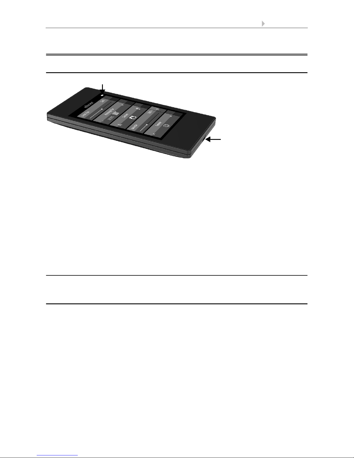
Charging
socket
Battery charging status indicator

8 Using the remote control
Remote Control Remo KNX RF • Version: 15.01.2019 • Technical changes and errors excepted.
3. Using the remote control
3.1. Automatic switch-off
The display of the remote control switches on when the device is moved (e.g. if the remote
control is picked up) and switches off again after several seconds to save energy. The time
until switch-off can be set in the Display menu (see Chapter 3.2. Display, page 8).
3.2. Display
The display shows all channels one after another. The sequence can be changed in the
Wireless channel configuration > Change channel order menu (see manual, Chapter
Change channel order). Keep in mind that access to these setting menus can be locked.
Locking/unlocking can be done via the ETS application or the bus (communication object).
If more than five drives/devices are taught, the display uses several pages to show them.
Use the Up/down arrow buttons to change page.
3.3. Operating drives and devices
3.3.1. Control media
e.g. music, film
The operating options available depend on the selection in the ETS. The following functions
are available:
Display view during first set-up
With multiple-page views, the media control can be accessed via the small button at the top right of Page 1.
If the view has only one page, the media page can be
opened via its own button.
9 Using the remote control
Remote Control Remo KNX RF • Version: 15.01.2019 • Technical changes and errors excepted.
3.3.2. Moving drives (Up/Down)
Shutter, blind, awning or window
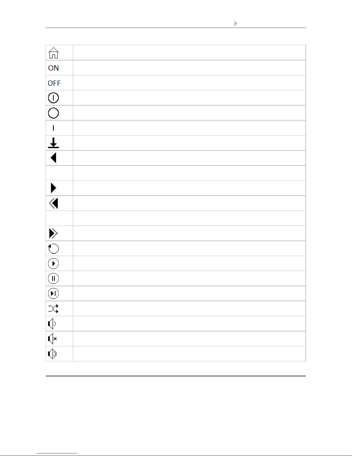
Back to remote control view (Page 1)
Switch device on
Switch device off
Switch device on/off (combined view)
Device is off (combined view)
Device is on (combined view)
Update
Previous title
Display title information, album, interpret
Next title
Previous playlist
Playlist view
Next playlist
Repeat
Play
Pause
Play/Pause (combined view)
Shuffle (play the titles in random order)
Higher
Mute
Lower
10 Using the remote control
Remote Control Remo KNX RF • Version: 15.01.2019 • Technical changes and errors excepted.
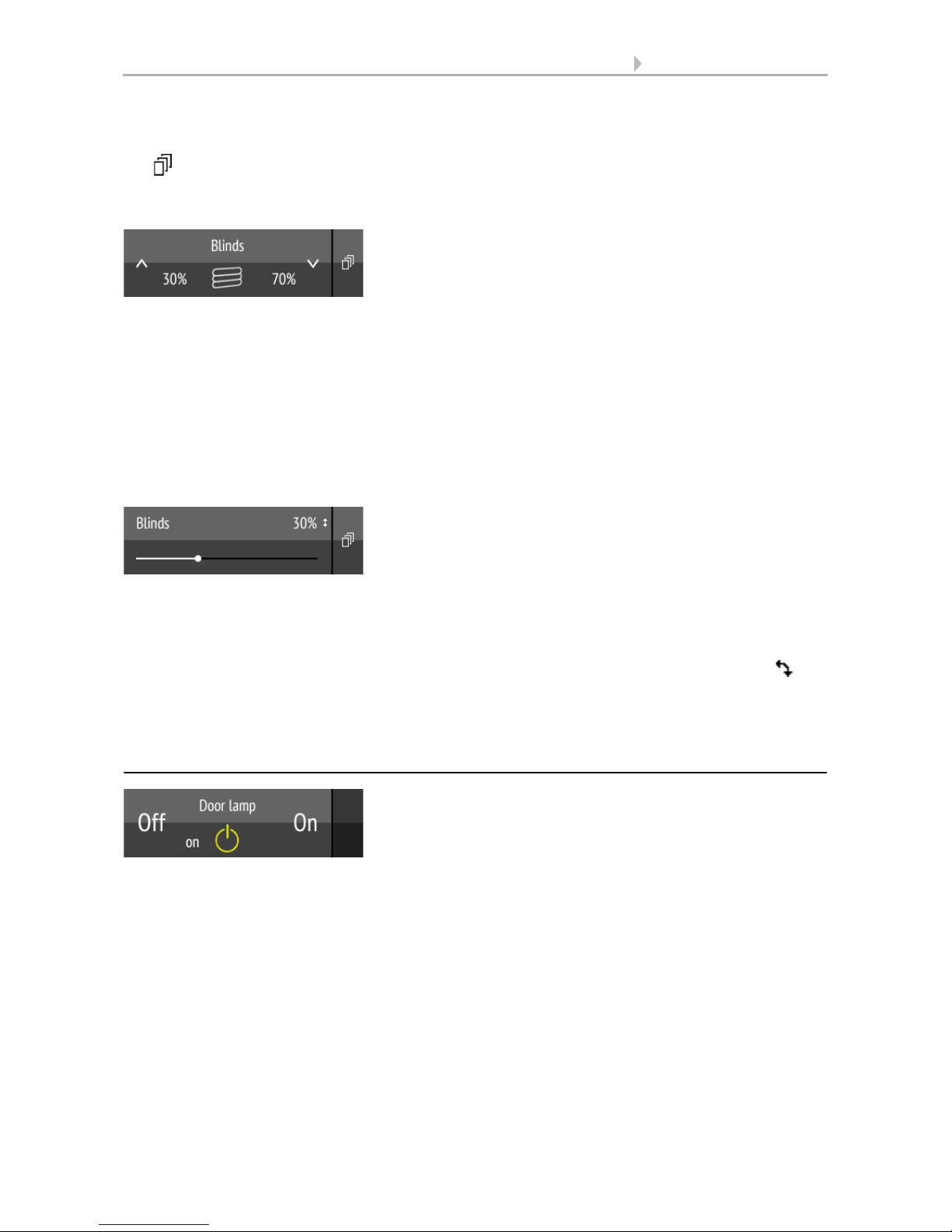
‘Buttons’ and ‘sliders’ can be activated as operating interfaces in the ETS. If multiple interfaces are active, you can switch between the views using the right area of the bar (side symbol ).
Buttons:
Tap on the up or down arrow to position the drive.
The reaction of the buttons to the short tap/longer holding, as well as the display of the position, depends on the settings in the ETS.
The position of the drive is shown in the button, left of the symbol, if the ‘Feedback’ setting
was activated in the ETS. With shutters, the slat position can also be displayed (right side
of the symbol).
Sliders:
Shift the point on the line to position the drive. If ‘feedback’ is activated in the ETS,
then the current curtain height will be displayed in %, and the position of the point on the
line will correspond to the current curtain position as soon as feedback is received.
In case of shutters, a second slider can be activated in the ETS for the slat position ( ).
ETS settings, see manual, Chapter Channel 1...8, sections about shutters, blinds, awnings
or windows.
3.3.3. Switching devices (on/off)
Tapping the right side of the bar switches the device on. Tapping the left side of
the bar switches the device off. The buttons can be provided with a label, in the ETS,
in the menu Wireless channel configuration > On/Off text (see manual, Chapter Changing
the On/Off Text).
If the ‘Feedback’ setting is activated in the ETS, the status reported by the bus (text, on/yellow symbol or off/grey symbol) is displayed. Otherwise, there is no feedback for the status.
The feedback text can be changed in the ETS in the menu Wireless channel configuration >
Feedback text (see manual, Chapter Changing the Feedback Text).
For ETS settings, see manual, Chapter Channel 1...8, section Switching.
 Loading...