

Elsner KNX S1E-UP 230V, KNX S1E-B2-UP 230 V, KNX S1E-B4-UP 230 V Installation And Adjustment Manual
Installation and Adjustment
EN
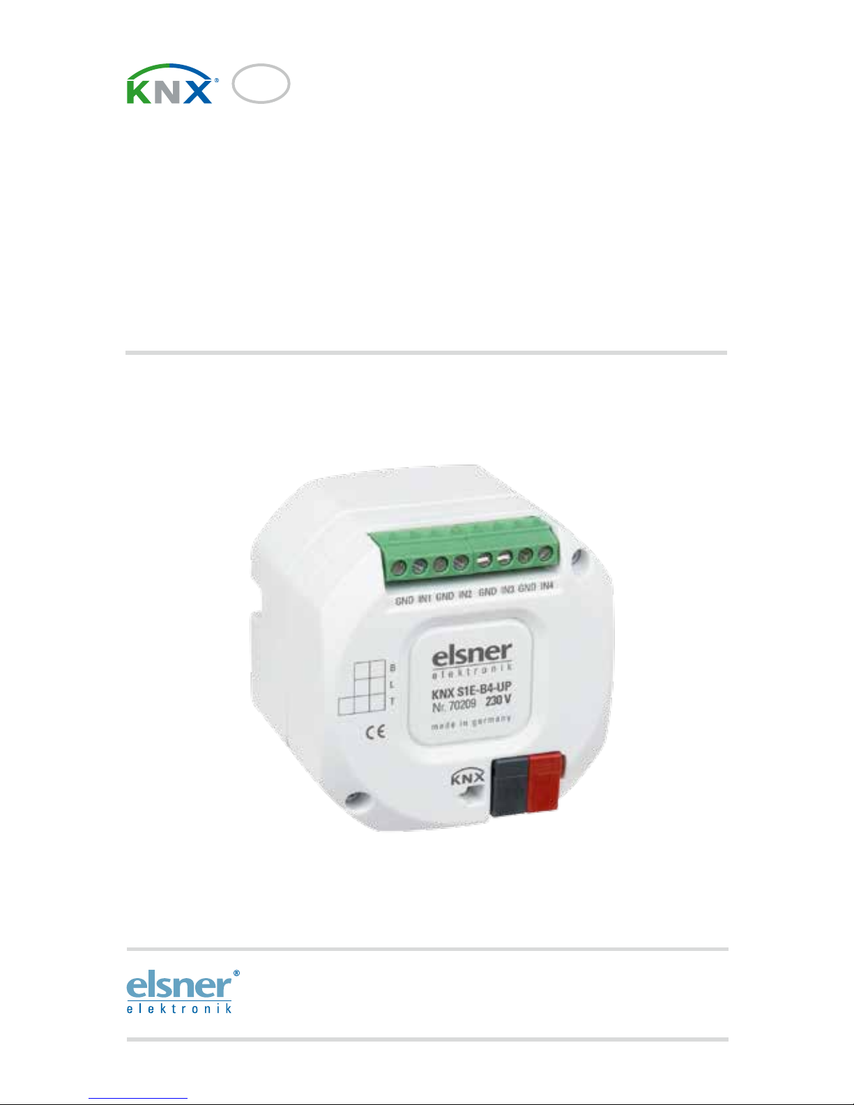
KNX S1E-UP 230V
KNX S1E-B2-UP 230 V
KNX S1E-B4-UP 230 V
Multifunctional Actuators
Item numbers 70207, 70208, 70209

1 Contents
Elsner Elektronik GmbH • Sohlengrund 16 • 75395 Ostelsheim • Germany
Actuators KNX S1E 230 V • from software version 1.00, ETS programme version 1.0
Status: 19.04.2016 • Subject to technical changes. Errors excepted.
1. Description ........................................................................................... 3
1.1. Technical specification ............................................................................................. 4
2. Installation and commissioning ........................................................... 4
2.1. Installation notes ...................................................................................................... 4
2.2. Installation ................................................................................................................ 5
2.3. Connection ................................................................................................................ 6
2.3.1. Connection examples ................................................................................... 7
2.4. Instructions for assembly and initial start-up ........................................................ 8
3. Addressing of the device at the bus .................................................... 8
4. Transfer protocol ................................................................................. 9
4.1. List of all communication objects ........................................................................... 9
5. Parameter setting .............................................................................. 20
5.1. General settings ..................................................................................................... 20
5.2. Output ..................................................................................................................... 20
5.2.1. Channel settings – drives ........................................................................... 20
5.2.1.1. Control (drives) ............................................................................ 23
Block – blocking objects ............................................................................. 27
Block – wind blocking ................................................................................. 28
Block – rain blocking ................................................................................... 29
5.2.1.2. Automatic for shading (drives) .................................................... 29
5.2.1.3. Automatic for windows (drives) .................................................. 34
5.2.1.4. Button inputs (drives) ................................................................... 38
Input as bus button ..................................................................................... 38
Input as actuator button ............................................................................. 42
Input as zero position sensor ..................................................................... 43
5.3. Temperature threshold values .............................................................................. 43
5.3.1. Temperature threshold value 1, 2, 3, 4 ..................................................... 43
5.3.2. Logic ............................................................................................................ 45
5.3.3. AND and/or OR logic 1/2/3/4 ...................................................................... 46
5.3.4. AND logic connection inputs ..................................................................... 47
5.3.5. Connection inputs of the OR logic ............................................................. 48
6. General part ....................................................................................... 49
6.1. Output channel with drive ..................................................................................... 49
6.1.1. Control modi for drive control ................................................................... 49
2 Clarification of signs
This manual is amended periodically and will be brought into line with new software
releases. The change status (software version and date) can be found in the contents footer.
If you have a device with a later software version, please check
www.elsner-elektronik.de in the menu area "Service" to find out whether a more up-todate version of the manual is available.
Clarification of signs used in this manual
Installation, inspection, commissioning and troubleshooting of the device
must only be carried out by a competent electrician.
Safety advice.
Safety advice for working on electrical connections, components,
etc.
DANGER!
... indicates an immediately hazardous situation which will lead to
death or severe injuries if it is not avoided.
WARNING!
... indicates a potentially hazardous situation which may lead to
death or severe injuries if it is not avoided.
CAUTION!
... indicates a potentially hazardous situation which may lead to
trivial or minor injuries if it is not avoided.
ATTENTION!
... indicates a situation which may lead to damage to property if it is
not avoided.
ETS In the ETS tables, the parameter default settings are marked by
underlining.

3 Description
Actuators KNX S1E 230 V • Version: 19.04.2016 • Technical changes and errors excepted.
1. Description
With the Actuators KNX S1E 230 V with integrated façade controller a 230 V ACmotor for a shutter, an awning, a blind or window is controlled. The electronic output
switches silently.
The automation for the drive control is specified externally or internally. Internally,
there are numerous options available for blocking, locking (e.g. master-slave) and priority definitions (e.g. manual-automatic). Scenes are saved and called up via the bus
(scene control with 16 scenes per drive).
The KNX S1E-B4-UP and KNX S1E-B2-UP models are equipped with inputs which
are used as bus inputs (buttons, alarms, etc.) or for T-NTC temperature sensors. The
KNX S1E-UP model does not have any analogue/digital inputs.
Functions:
•Electronic output for a 230 V-drive (shade, window)
• Inputs for binary contact or temperature sensor (not on KNX S1E-UP)
• Automatic runtime measurement of the drives for positioning (incl. fault
reporting object)
• Position feedback (movement position, also slat position for shutters)
• Position storage (movement position) via 1-bit object (storage and call-up
e.g. via buttons)
• Parameters for taking drive and mechanics downtimes into account
•Control via internal or external automation functions
•Integrated shade control with slat tracking according to sun position for
shutters
• Scene control for movement position with 16 scenes per drive (also slat
position for shutters)
• Mutual locking of two drives using zero position sensors prevents collisions
e.g. of shade and window (master–slave)
• Blocking objects and alarm reports have different priorities, so safety functions
always take precedence (e.g. wind block)
• Manual or automatic priority setting via time or communication object
• 4 temperature switching outputs in the application program with
adjustable threshold values (presetting the parameters or communication
object)
• 4 AND and 4 OR logic gates each with 4 inputs. 16 logic inputs (in the form
of communication objects) are available as inputs for the logic gates. The
output from each gate can be configured optionally as 1-bit or 2 x 8-bit
Configuration is made using the KNX software ETS. The product file can be downloaded from the Elsner Elektronik website on www.elsner-elektronik.de in the “Service” menu.

4 Installation and commissioning
Actuators KNX S1E 230 V • Version: 19.04.2016 • Technical changes and errors excepted.
1.1. Technical specification
The product is compliant with the provisions of EU guidelines.
2. Installation and commissioning
2.1. Installation notes
Installation, testing, operational start-up and troubleshooting should
only be performed by an electrician.
Housing Plastic
Colour White
Assembly Flush mounting (in junction box Ø 60 mm, 60 mm
deep)
Protection category IP 20
Dimensions approx. 50 x 50 x 54 (W × H × D, mm)
Weight approx. 100 g
Ambient temperature Operation -20…+50°C, storage -30…+85°C
Ambient humidity 5...80% RH, non-condensing
Operating voltage KNX bus voltage
Current at the bus 10 mA
Output 1 × Output
(Power supply, PE/N/Up/Down),
Loadable to a maximum of 400 W
Minimum load for run time
recording
40 W
Inputs KNX S1E-UP 230 V: no inputs.
KNX S1E-B2-UP 230 V: 2× analogue/digital.
KNX S1E-B4-UP 230 V: 4× analogue/digital.
max. output length 10 m.
Setting range for the T-NTC
temperature sensor at the
input
-30°C...+80°C
Data output KNX +/- bus plug-in terminals
BCU type Integrated microcontroller
PEI type 0
Group addresses max. 1024
Assignments max. 1024
Communication objects KNX S1E-UP 230 V: 186
KNX S1E-B2-UP 230 V: 213
KNX S1E-B4-UP 230 V: 239

5 Installation and commissioning
Actuators KNX S1E 230 V • Version: 19.04.2016 • Technical changes and errors excepted.
DANGER!
Risk to life from live voltage (mains voltage)!
There are unprotected live components within the device.
• VDE regulations and national regulations are to be followed.
• Ensure that all lines to be assembled are free of voltage and take
precautions against accidental switching on.
• Do not use the device if it is damaged.
• Take the device or system out of service and secure it against
unintentional use, if it can be assumed, that risk-free operation is no
longer guaranteed.
The device is only to be used for its intended purpose. Any improper modification or
failure to follow the operating instructions voids any and all warranty and guarantee
claims.
After unpacking the device, check it immediately for possible mechanical damage. If it
has been damaged in transport, inform the supplier immediately.
The device may only be used as a fixed-site installation; that means only when assembled and after conclusion of all installation and operational start-up tasks and only in
the surroundings designated for it.
Elsner Elektronik is not liable for any changes in norms and standards which may occur
after publication of these operating instructions.
2.2. Installation
Fig. 1: Output side
1 Connecting terminal for drive 230 V AC
1
6 Installation and commissioning
Actuators KNX S1E 230 V • Version: 19.04.2016 • Technical changes and errors excepted.
Devices with inputs (KNX S1E-B4-UP, KNX S1E-B2-UP):
Device without input (KNX S1E-UP):
2.3. Connection
The Actuators KNX S1E 230 V are installed in a flush-mounted socket. The connection of the KNX data bus is done using KNX connectors. In addition, a 230 V AC mains
supply is necessary for the drive connected (L).
The physical address is assigned by the KNX software. There is a button with a control
LED for this on the actuator.
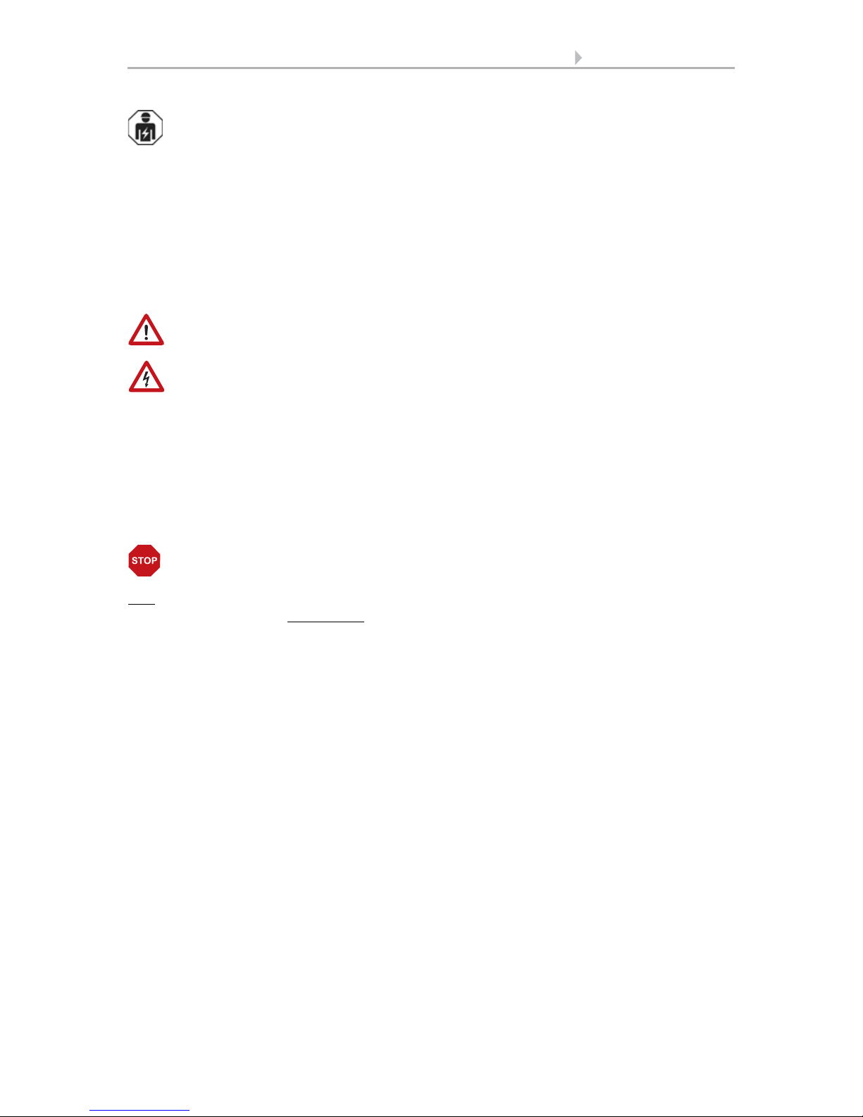
Fig. 2: Bus side
1 Connecting terminal analogue/ digital
outputs (not present on KNX S1E-UP)
2 Label field
3 KNX plug terminal +/4 Programming LED and programming
button (countersunk)
1
2
3
4
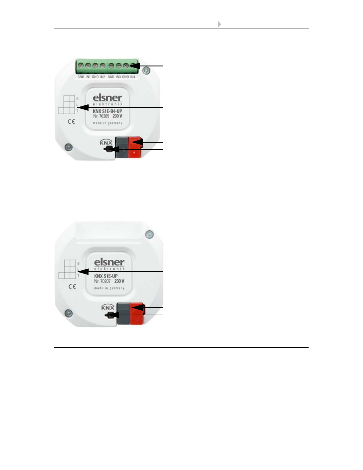
Analogue/digital inputs connector assignment:
KNX S1E-B2-UP 230V: 1: GND | 2: IN1 | 3: GND | 4: IN2
KNX S1E-B4-UP 230V: 1: GND | 2: IN1 | 3: GND | 4: IN2 | 5: GND | 6: IN3 | 7: GND | 8: IN4
All GND connectors are internally bridged.
Fig. 3: Bus side
1 Label field
2 KNX plug terminal +/3 Programming LED and programming
button (countersunk)
1
2
3
7 Installation and commissioning
Actuators KNX S1E 230 V • Version: 19.04.2016 • Technical changes and errors excepted.
2.3.1. Connection examples
Inputs:
230 V drive at the output:
Mains
(230 V)
Example KNX S1E-B4-UP with
binary contact on input 1 and
T-NTC temperature sensor on input 4.
Connection of the temperature sensor is
independent of the polarity.

8 Addressing of the device at the bus
Actuators KNX S1E 230 V • Version: 19.04.2016 • Technical changes and errors excepted.
2.4. Instructions for assembly and initial start-up
Never expose actuators to water (e.g. rain) or dust. This can damage the electronics.
You must not exceed a relative air humidity of 80%. Avoid condensation.
After the auxiliary voltage has been applied, the device will enter an initialisation phase
lasting a few seconds. During this phase no information can be received or sent via the
bus.
For KNX devices with safety functions (e.g. wind or rain blocks), it is important to set
up periodical monitoring of the safety objects. The ideal ratio is 1:3 (example: if the
weather station sends a value every 5 minutes, the actuator must be configured for a
monitoring period of 15 minutes).
3. Addressing of the device at the bus
The device is supplied with the bus address 15.15.250. You can program another address into the ETS by overwriting the 15.15.250 address or by teaching via the programming key.

9 Transfer protocol
Actuators KNX S1E 230 V • Status: 19.04.2016 • Technical changes and errors excepted.
4. Transfer protocol
4.1. List of all communication objects
Abbreviations:
R Read
WWrite
C Communication
T Transfer
DPT Data Point Type
No Text Function Flags DPT Typ Size
1 Software version Readable R-C- [217.1] DPT_Version 2 Bytes
10 Channel A - Automatic or
manual status
Output R-CT [1] 1.xxx 1 Bit
11 Channel A - Manual
extended
Input RWC- [1.8] DPT_UpDown 1 Bit
12 Channel A - Manual brief Input RWC- [1.8] DPT_UpDown 1 Bit
13 Channel A - Manual
movement position
Input RWC- [5.1] DPT_Scaling 1 Byte
14 Channel A - Manual slat
position
Input RWC- [5.1] DPT_Scaling 1 Byte
15 Channel A - Automatic
extended
Input RWC- [1.8] DPT_UpDown 1 Bit
16 Channel A - Automatic brief Input RWC- [1.8] DPT_UpDown 1 Bit
17 Channel A - Automatic
movement position
Input RWC- [5.1] DPT_Scaling 1 Byte
18 Channel A - Automatic slat
position
Input RWC- [5.1] DPT_Scaling 1 Byte
19 Channel A - Switch from
manual to automatic
Input RWC- [1] 1.xxx 1 Bit
20 Channel A - Automatic
blocking object
Input RWC- [1.1] DPT_Switch 1 Bit
21 Channel A - Current
movement position
Output R-CT [5.1] DPT_Scaling 1 Byte
22 Channel A - Current slat
position
Output R-CT [5.1] DPT_Scaling 1 Byte
23 Channel A - Status object Output R-CT [1] 1.xxx 1 Bit
24 Channel A - Call up / saving
scenes
Input RWC- [18.1]
DPT_SceneControl
1 Byte
25 Channel A - Outdoor
temperature blocking object
Input RWC- [1.1] DPT_Switch 1 Bit

10 Transfer protocol
Actuators KNX S1E 230 V • Status: 19.04.2016 • Technical changes and errors excepted.
26 Channel A - Outdoor
temperature blocking
measurement value
Input RWC- [9.1]
DPT_Value_Temp
2 Bytes
27 Channel A - Outdoor
temperature blocking status
Output R-CT [1.1] DPT_Switch 1 Bit
28 Channel A - Twilight object Input RWC- [1.1] DPT_Switch 1 Bit
29 Channel A - Twilight
measurement value
Input RWC- [9.4] DPT_Value_Lux 2 Bytes
30 Channel A - Twilight status Output R-CT [1.1] DPT_Switch 1 Bit
31 Channel A - Time control Input RWC- [1.1] DPT_Switch 1 Bit
32 Channel A - Inside
temperature release object
Input RWC- [1.1] DPT_Switch 1 Bit
33 Channel A - Inside
temperature release
measurement value
Input RWC- [9.1]
DPT_Value_Temp
2 Bytes
34 Channel A - Inside
temperature release target
value
Input RWC- [9.1]
DPT_Value_Temp
2 Bytes
35 Channel A - Inside
temperature release status
Output R-CT [1.1] DPT_Switch 1 Bit
36 Channel A - Shading object Input RWC- [1.1] DPT_Switch 1 Bit
37 Channel A - Shading
brightness measurement
value 1
Input RWC- [9.4] DPT_Value_Lux 2 Bytes
38 Channel A - Shading
brightness measurement
value 2
Input RWC- [9.4] DPT_Value_Lux 2 Bytes
39 Channel A - Shading
brightness measurement
value 3
Input RWC- [9.4] DPT_Value_Lux 2 Bytes
40 Channel A - Shading
threshold value
Input /
Output
RWCT [9.4] DPT_Value_Lux 2 Bytes
41 Channel A - Shading
threshold value 1 = + | 0 = -
Input RWC- [1] 1.xxx 1 Bit
42 Channel A - Shading
threshold value +
Input RWC- [1] 1.xxx 1 Bit
43 Channel A - Shading
threshold value -
Input RWC- [1] 1.xxx 1 Bit
44 Channel A - Shading status Output R-CT [1.1] DPT_Switch 1 Bit
45 Channel A - Shading
position learning object
Input RWC- [1] 1.xxx 1 Bit
46 Channel A - Azimuth Input RWC- [9] 9.xxx 2 Bytes
47 Channel A - Elevation Input RWC- [9] 9.xxx 2 Bytes
No Text Function Flags DPT Typ Size

11 Transfer protocol
Actuators KNX S1E 230 V • Status: 19.04.2016 • Technical changes and errors excepted.
48 Channel A - Cold air intake
blocking object
Input RWC- [1.1] DPT_Switch 1 Bit
49 Channel A - Cold air intake
outside temp. measurement
value
Input RWC- [9.1]
DPT_Value_Temp
2 Bytes
50 Channel A - Cold air intake
blocking status
Output R-CT [1.1] DPT_Switch 1 Bit
51 Channel A - Forced
ventilation
Input RWC- [1.1] DPT_Switch 1 Bit
52 Channel A - Warm air intake
blocking object
Input RWC- [1.1] DPT_Switch 1 Bit
53 Channel A - Warm air intake
inside temp. measurement
value
Input RWC- [9.1]
DPT_Value_Temp
2 Bytes
54 Channel A - Warm air intake
outside temp. measurement
value
Input RWC- [9.1]
DPT_Value_Temp
2 Bytes
55 Channel A - Warm air intake
blocking target value
Input RWC- [9.1]
DPT_Value_Temp
2 Bytes
56 Channel A - Warm air intake
blocking status
Output R-CT [1.1] DPT_Switch 1 Bit
57 Channel A - Inside
temperature opening object
Input RWC- [1.1] DPT_Switch 1 Bit
58 Channel A - Inside temp.
opening measurement
value
Input RWC- [9.1]
DPT_Value_Temp
2 Bytes
59 Channel A - Inside temp.
opening target value
Input RWC- [9.1]
DPT_Value_Temp
2 Bytes
60 Channel A - Inside temp.
opening threshold value
Input /
Output
RWCT [9.1]
DPT_Value_Temp
2 Bytes
61 Channel A - Inside temp.
open threshold value 1 = +
Input RWC- [1] 1.xxx 1 Bit
62 Channel A - Inside temp.
opening threshold value +
Input RWC- [1] 1.xxx 1 Bit
63 Channel A - Inside temp.
opening threshold value -
Input RWC- [1] 1.xxx 1 Bit
64 Channel A - Inside temp.
opening object
Output R-CT [1.1] DPT_Switch 1 Bit
65 Channel A - Inside humidity
opening object
Input RWC- [1.1] DPT_Switch 1 Bit
66 Channel A - Inside humidity
opening measurement
value
Input RWC- [9.7]
DPT_Value_Humidity
2 Bytes
67 Channel A - Inside humidity
opening status
Output R-CT [1.1] DPT_Switch 1 Bit
No Text Function Flags DPT Typ Size

12 Transfer protocol
Actuators KNX S1E 230 V • Status: 19.04.2016 • Technical changes and errors excepted.
68 Channel A - Approach
position memory
automatically
Input RWC- [1.1] DPT_Switch 1 Bit
69 Channel A - Learn object
position memory
automatically
Input RWC- [1.1] DPT_Switch 1 Bit
70 Channel A - Zero position
reached
Input RWC- [1.1] DPT_Switch 1 Bit
71 Channel A - Zero position
sensor disrupted
Output R-CT [1.1] DPT_Switch 1 Bit
72 Channel A - Master zero
position status
Output R-CT [1.1] DPT_Switch 1 Bit
73 Channel A - Master zero
position command
Output R-CT [1.1] DPT_Switch 1 Bit
74 Channel A - Slave zero
position status
Input RWC- [1.1] DPT_Switch 1 Bit
75 Channel A - Master zero
position status
Input RWC- [1.1] DPT_Switch 1 Bit
76 Channel A - Master zero
position command
Input RWC- [1.1] DPT_Switch 1 Bit
77 Channel A - Slave zero
position status
Output R-CT [1.1] DPT_Switch 1 Bit
78 Channel A - Drive is moving Output R-CT [1] 1.xxx 1 Bit
79 Channel A - Object
malfunction
Output R-CT [1] 1.xxx 1 Bit
80 Channel A - Blocking 1 -
Blocking object
Input RWC- [1.1] DPT_Switch 1 Bit
81 Channel A - Blocking 1 -
Wind blocking object
Input RWC- [1.1] DPT_Switch 1 Bit
82 Channel A - Blocking 1 -
Wind blocking
measurement value
Input RWC- [9.5] DPT_Value_Wsp 2 Bytes
83 Channel A - Blocking 1 -
Wind blocking status
Output R-CT [1.1] DPT_Switch 1 Bit
84 Channel A - Blocking 1 -
Rain blocking object
Input RWC- [1.1] DPT_Switch 1 Bit
85 Channel A - Blocking 2 -
Blocking object
Input RWC- [1.1] DPT_Switch 1 Bit
86 Channel A - Blocking 2 -
Wind blocking object
Input RWC- [1.1] DPT_Switch 1 Bit
87 Channel A - Blocking 2 -
Wind blocking
measurement value
Input RWC- [9.5] DPT_Value_Wsp 2 Bytes
88 Channel A - Blocking 2 -
Wind blocking status
Output R-CT [1.1] DPT_Switch 1 Bit
No Text Function Flags DPT Typ Size

13 Transfer protocol
Actuators KNX S1E 230 V • Status: 19.04.2016 • Technical changes and errors excepted.
89 Channel A - Blocking 2 -
Rain blocking object
Input RWC- [1.1] DPT_Switch 1 Bit
90 Channel A - Blocking 3 -
Blocking object
Input RWC- [1.1] DPT_Switch 1 Bit
91 Channel A - Blocking 3 -
Wind blocking object
Input RWC- [1.1] DPT_Switch 1 Bit
92 Channel A - Blocking 3 -
Wind blocking
measurement value
Input RWC- [9.5] DPT_Value_Wsp 2 Bytes
93 Channel A - Blocking 3 -
Wind blocking status
Output R-CT [1.1] DPT_Switch 1 Bit
94 Channel A - Blocking 3 -
Rain blocking object
Input RWC- [1.1] DPT_Switch 1 Bit
95 Channel A - Blocking 4 -
Blocking object
Input RWC- [1.1] DPT_Switch 1 Bit
96 Channel A - Blocking 4 -
Wind blocking object
Input RWC- [1.1] DPT_Switch 1 Bit
97 Channel A - Blocking 4 -
Wind blocking
measurement value
Input RWC- [9.5] DPT_Value_Wsp 2 Bytes
98 Channel A - Blocking 4 -
Wind blocking status
Output R-CT [1.1] DPT_Switch 1 Bit
99 Channel A - Blocking 4 -
Rain blocking object
Input RWC- [1.1] DPT_Switch 1 Bit
100 Channel A - Blocking 5 -
Blocking object
Input RWC- [1.1] DPT_Switch 1 Bit
101 Channel A - Blocking 5 -
Wind blocking object
Input RWC- [1.1] DPT_Switch 1 Bit
102 Channel A - Blocking 5 -
Wind blocking
measurement value
Input RWC- [9.5] DPT_Value_Wsp 2 Bytes
103 Channel A - Blocking 5 -
Wind blocking status
Output R-CT [1.1] DPT_Switch 1 Bit
104 Channel A - Blocking 5 -
Rain blocking object
Input RWC- [1.1] DPT_Switch 1 Bit
105 Channel A - Short time
restriction
Input RWC- [1.1] DPT_Switch 1 Bit
Input 1 and 2 only for KNX S1E-B2-UP and KNX S1E-B4-UP
150 Input 1 - Extended Input /
Output
RWCT [1.8] DPT_UpDown 1 Bit
151 Input 1 - Short Output R-CT [1.8] DPT_UpDown 1 Bit
152 Input 1 - Switching Input /
Output
RWCT [1.1] DPT_Switch 1 Bit
No Text Function Flags DPT Typ Size

14 Transfer protocol
Actuators KNX S1E 230 V • Status: 19.04.2016 • Technical changes and errors excepted.
153 Input 1 - Relative dimming Input /
Output
RWCT [3.7]
DPT_Control_Dimmin
g
4 Bit
154 Input 1 - 8-bit encoder Output R-CT [5] 5.xxx 1 Byte
155 Input 1 - Temperature
encoder
Output R-CT [9.1]
DPT_Value_Temp
2 Bytes
156 Input 1 - Brightness encoder Output R-CT [9.4] DPT_Value_Lux 2 Bytes
157 Input 1 - Scene Output R-CT [18.1]
DPT_SceneControl
1 Byte
158 Input 1 - Blocking object Input RWC- [1.1] DPT_Switch 1 Bit
160 Input 1 - Temperature
sensor, malfunction
Output --CT [1.1] DPT_Switch 1 Bit
161 Input 1 - Temperature
sensor, total value
Output R-CT [9.1]
DPT_Value_Temp
2 Bytes
162 Input 1 - Temperature
sensor, measured outside
value
Input -WC- [9.1]
DPT_Value_Temp
2 Bytes
163 Input 1 - Temperature
sensor, measured value
Output R-CT [9.1]
DPT_Value_Temp
2 Bytes
170 Input 2 - Extended Input /
Output
RWCT [1.8] DPT_UpDown 1 Bit
171 Input 2 - Short Output R-CT [1.8] DPT_UpDown 1 Bit
172 Input 2 - Switching Input /
Output
RWCT [1.1] DPT_Switch 1 Bit
173 Input 2 - Relative dimming Input /
Output
RWCT [3.7]
DPT_Control_Dimmin
g
4 Bit
174 Input 2 - 8-bit encoder Output R-CT [5] 5.xxx 1 Byte
175 Input 2 - Temperature
encoder
Output R-CT [9.1]
DPT_Value_Temp
2 Bytes
176 Input 2 - Brightness encoder Output R-CT [9.4] DPT_Value_Lux 2 Bytes
177 Input 2 - Scene Output R-CT [18.1]
DPT_SceneControl
1 Byte
178 Input 2 - Blocking object Input RWC- [1.1] DPT_Switch 1 Bit
180 Input 2 - Temperature
sensor, malfunction
Output --CT [1.1] DPT_Switch 1 Bit
181 Input 2 - Temperature
sensor, total value
Output R-CT [9.1]
DPT_Value_Temp
2 Bytes
182 Input 2 - Temperature
sensor, measured outside
value
Input -WC- [9.1]
DPT_Value_Temp
2 Bytes
183 Input 2 - Temperature
sensor, measured value
Output R-CT [9.1]
DPT_Value_Temp
2 Bytes
Input 3 and 4 only for KNX S1E-B4-UP
No Text Function Flags DPT Typ Size

15 Transfer protocol
Actuators KNX S1E 230 V • Status: 19.04.2016 • Technical changes and errors excepted.
190 Input 3 - Extended Input /
Output
RWCT [1.8] DPT_UpDown 1 Bit
191 Input 3 - Short Output R-CT [1.8] DPT_UpDown 1 Bit
192 Input 3 - Switching Input /
Output
RWCT [1.1] DPT_Switch 1 Bit
193 Input 3 - Relative dimming Input /
Output
RWCT [3.7]
DPT_Control_Dimmin
g
4 Bit
194 Input 3 - 8-bit encoder Output R-CT [5] 5.xxx 1 Byte
195 Input 3 - Temperature
encoder
Output R-CT [9.1]
DPT_Value_Temp
2 Bytes
196 Input 3 - Brightness encoder Output R-CT [9.4] DPT_Value_Lux 2 Bytes
197 Input 3 - Scene Output R-CT [18.1]
DPT_SceneControl
1 Byte
198 Input 3 - Blocking object Input RWC- [1.1] DPT_Switch 1 Bit
200 Input 3 - Temperature
sensor, malfunction
Output --CT [1.1] DPT_Switch 1 Bit
201 Input 3 - Temperature
sensor, total value
Output R-CT [9.1]
DPT_Value_Temp
2 Bytes
202 Input 3 - Temperature
sensor, measured outside
value
Input -WC- [9.1]
DPT_Value_Temp
2 Bytes
203 Input 3 - Temperature
sensor, measured value
Output R-CT [9.1]
DPT_Value_Temp
2 Bytes
210 Input 4 - Extended Input /
Output
RWCT [1.8] DPT_UpDown 1 Bit
211 Input 4 - Short Output R-CT [1.8] DPT_UpDown 1 Bit
212 Input 4 - Switching Input /
Output
RWCT [1.1] DPT_Switch 1 Bit
213 Input 4 - Relative dimming Input /
Output
RWCT [3.7]
DPT_Control_Dimmin
g
4 Bit
214 Input 4 - 8-bit encoder Output R-CT [5] 5.xxx 1 Byte
215 Input 4 - Temperature
encoder
Output R-CT [9.1]
DPT_Value_Temp
2 Bytes
216 Input 4 - Brightness encoder Output R-CT [9.4] DPT_Value_Lux 2 Bytes
217 Input 4 - Scene Output R-CT [18.1]
DPT_SceneControl
1 Byte
218 Input 4 - Blocking object Input RWC- [1.1] DPT_Switch 1 Bit
220 Input 4 - Temperature
sensor, malfunction
Output --CT [1.1] DPT_Switch 1 Bit
221 Input 4 - Temperature
sensor, total value
Output R-CT [9.1]
DPT_Value_Temp
2 Bytes
No Text Function Flags DPT Typ Size
 Loading...