

Elsner KNX PS640+IP Installation And Adjustment Manual
Power Supply System
KNX PS640+IP
with Bus Functions and Ethernet Interface
Item Number 70145
Installation and Adjustment
Elsner Elektronik GmbH Control and Automation Technology
Sohlengrund 16 | 75395 Ostelsheim | Germany
Tel.: +49 (0) 70 33 / 30 945 - 0 | Fax: +49 (0) 70 33 / 30 945 - 20
info@elsner-elektronik.de | www.elsner-elektronik.de

2
Contents
Product description ....................................................................................................... 3
Technical data ...................................................................................................................................... 4
Application examples .................................................................................................... 4
IP Interface ............................................................................................................................................ 4
Installation and commissioning .................................................................................... 7
Connection ........................................................................................................................................... 7
KNX communication of IP interface and power supply unit ......................................... 8
Addressing ........................................................................................................................................... 9
Settings in der ETS .............................................................................................................................. 9
Settings at the device ................................................................................................... 9
Starting position .................................................................................................................................. 9
Line reset ............................................................................................................................................ 10
Data memory ..................................................................................................................................... 10
Operating data ................................................................................................................................... 12
Language ............................................................................................................................................ 12
Addressing the power supply unit (programming mode) ............................................................. 12
Setting of parameters in the ETS ................................................................................ 14
Parameters of the IP interface .......................................................................................................... 14
Communication settings in the ETS ............................................................................ 20
Setting the bus functions of the power supply unit in the ETS .................................. 21
Transmission protocol ...................................................................................................................... 21
Parameters of the power supply unit .............................................................................................. 22
KNX PS640+IP from software version display 3.3, IP chip 2.0, ETS programme version 1.0
Version: 23.02.2016. Errors excepted. Subject to technical changes.

3
Product description
The Power Supply System KNX PS640-IP combines the central functions of a KNX bus
line:
Power supply with throttle and bus communication
IP router and IP interface
The device has got two KNX interfaces, one for the “PLUS” functions of the power
supply unit and one for the IP router. The functions are registered at the bus separately
and parametrised in different product files (ETS).
The power supply unit of the KNX PS640+IP delivers a 29 V bus voltage for the KNX
system and 24 V DC supply voltage for 24 V devices. Special operating conditions such
as short circuit, electrical surge, overcharge or excess temperature are recorded and
may be read off on the display. The present power discharge is displayed as well. It is
possible to reset the connected bus devices directly by means of the key pad.
In addition all functions can be realised via the bus, too, e. g. the transfer of malfunction
messages and operating data and a time/period reset. Malfunction messages are stored
by the KNX PS640+IP.
The IP router of the KNX PS640+IP allows for forwarding of telegrams between
different lines via a rapid LAN (IP) backbone. The KNX PS640+IP therefore also takes on
the function of a line coupler.
In parallel, the KNX PS640+IP can be used as interface for accessing the bus via IP.
Like this, the KNX system can be configured and supervised from any PC in the LAN
(Tunnelling). Access via smartphone (KNX app) is also possible.
This device works according to the KNXnet/IP specification using the core, the device
management, the tunnelling and the routing part. The router of KNX PS640+IP has a
filter table and is able to buffer up to 150 telegrams.
Functions:
Delivers a 29 V KNX bus voltage (reduced), output current max. 640 mA, short-
circuit proof
Delivers 24 V DC (not reduced), output current max. 150 mA
Reset of a line directly on the device
Record of operating hours, overload, external overvoltage, internal overvoltage,
short circuit and excess temperature
Display of operating data bus voltage, bus current and temperature of the device
The display may be shown in German, English, French, Italian, Spanish or Dutch
Bus connection for data transfer (e. g. malfunction messages, operating data)
Possibility for reset and diagnostic via the bus
Routing: Transfer of KNX data via LAN (rapid backbone)
Line coupler function via LAN
Tunnelling: Configuration and supervising of the KNX system from any PC in the
LAN, access via smartphone (KNX app)

4
Configuration is made using the KNX software ETS. The product file, the data sheet and
the manual can be downloaded from the Elsner Elektronik homepage on www.elsnerelektronik.de in the “Service” menu.
Technical data
Housing: Plastic material
Colour: White
Mounting: Snap-on fitting on mounting rails
Protection category: IP 20
Dimensions: approx. 123 x 89 x 61 (W x H x D, mm), 7 width units
Weight: approx. 370 g
Ambient temperature: Operation -5…+45 °C, Storage -25…+70°C
Ambient air humidity: max. 95% R. H., avoid bedewing
Operating voltage: 230 V AC , 50 Hz
Power consumption: Full load: approx. 28 W, Standby: approx. 2.7 W
Outputs: • KNX bus voltage 29 V (reduced),
Output current max. 640 mA, short-circuit proof
• 24 V DC (not reduced), Output current max. 150 mA
• KNX data
• LAN connector RJ45; 10BaseT (10Mbit/s), Supported
internet protocols: ARP, ICMP, IGMP, UDP/IP and DHCP
Data output KNX +/- bus terminal plug
BCU type Own microcontroller
PEI type 0
Group addresses max. 200
Allocations max. 200
Communication objects Power supply unit: 27
The product conforms with the provisions of EU guidelines.
Application examples
IP Interface
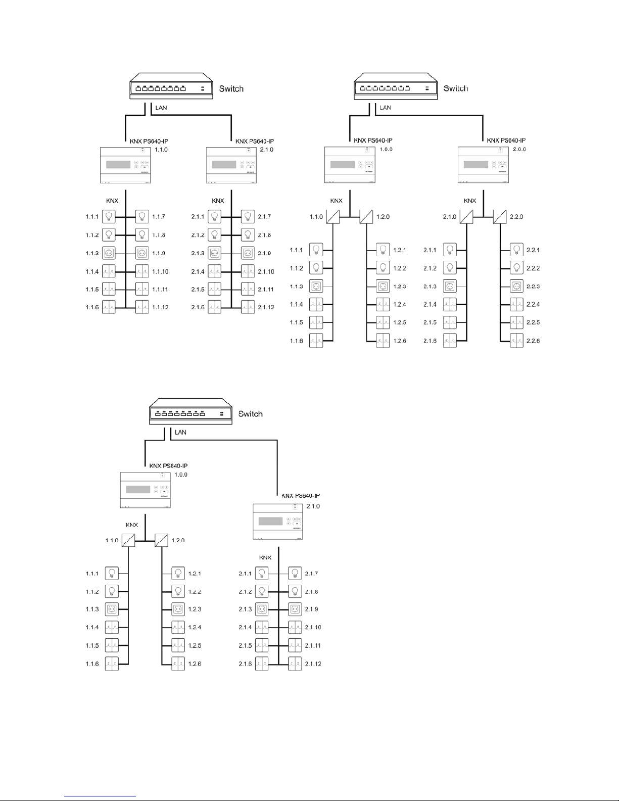
Coupler function (KNXnet/IP Routing)
The Power Supply System KNX PS640+IP can operate as a line and/or backbone
coupler. In both cases, the LAN (IP) acts as a backbone.
5
KNX PS640+IP as a line coupler KNX PS640+IP as a backbone coupler
KNX PS640+IP as a backbone and line coupler
The physical address assigned to the
KNX PS640+IP determines whether the
device operates as a line or backbone coupler. If the physical address is in the form of
x.y.0 (x, y: 1..15), the router operates as a line coupler. If it is in the form of x.0.0 (x:
1..15), the router acts as a backbone coupler.
6
Attention: If the KNX PS640+IP is used as a backbone coupler (x.0.0), there must be no
KNX IP Router in the topology beneath it. For example, if a KNX PS640+IP has the
physical address of 1.0.0, there must be no KNX IP Router with the address 1.1.0.
If the KNX PS640+IP is used as a line coupler (x.y.0), there must be no KNX IP Router in
the topology above it. For example, if a KNX PS640+IP has the physical address of 1.1.0,
there must be no KNX IP Router with the address 1.0.0.
The KNX PS640+IP has a filter table and thus contributes to reducing bus load. The filter
table is automatically generated by the ETS.
Because of the speed difference between the Ethernet (10 Mbit/s) and KNX (9.6 kbit/s), a
far greater number of telegrams can be transmitted on IP. If several consecutive
telegrams are transmitted on the same line, they must be buffered in the router to avoid
telegram loss. The KNX PS640+IP 750 has a memory for 150 telegrams (from IP to
KNX/EIB).
Bus access (KNXnet/IP Tunnelling)
The Power Supply System KNX PS640+IP can be used as an interface to KNX. KNX can
be accessed from any point in the LAN. For this purpose, a second physical address
must be assigned in the ETS. Please refer to chapter “ETS Connection Manager”.
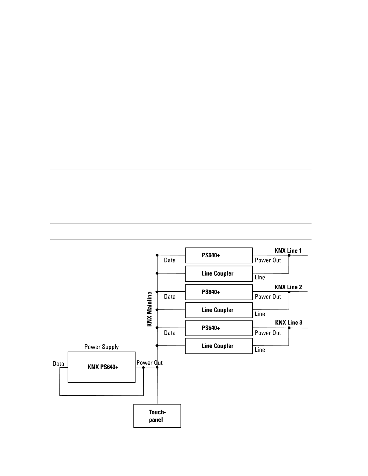
Power Supply
Housing example with central operating unit
7
Installation and commissioning
Installation, testing, operational start-up and troubleshooting should only be
performed by an electrician.
DANGER! Risk to life from live voltage (mains voltage)!
There are unprotected live components inside the device.
• VDE and national regulations are to be followed.
• Ensure that all lines to be assembled are free of voltage and take
precautions against accidental switching on.
• Do not use the device if it is damaged.
• Take the device or system out of service and secure it against unintentional
use, if it can be assumed, that risk-free operation is no longer guaranteed.
The device is only to be used for its intended purpose. Any improper modification or
failure to follow the operating instructions voids any and all warranty and guarantee
claims.
After unpacking the device, check it immediately for possible mechanical damage. If it
has been damaged in transport, inform the supplier immediately.
The device may only be used as a fixed-site installation; that means only when
assembled and after conclusion of all installation and operational start-up tasks and
only in the surroundings designated for it.
Elsner Elektronik is not liable for any changes in norms and standards which may occur
after publication of these operating instructions.
Connection
Observe the correct installation. Incorrect installation may destroy the power supply
system or connected electronic devices.
After the auxiliary voltage is applied the device will enter an initialization phase lasting
about 5 seconds. During this phase no information can be received via the bus.
8
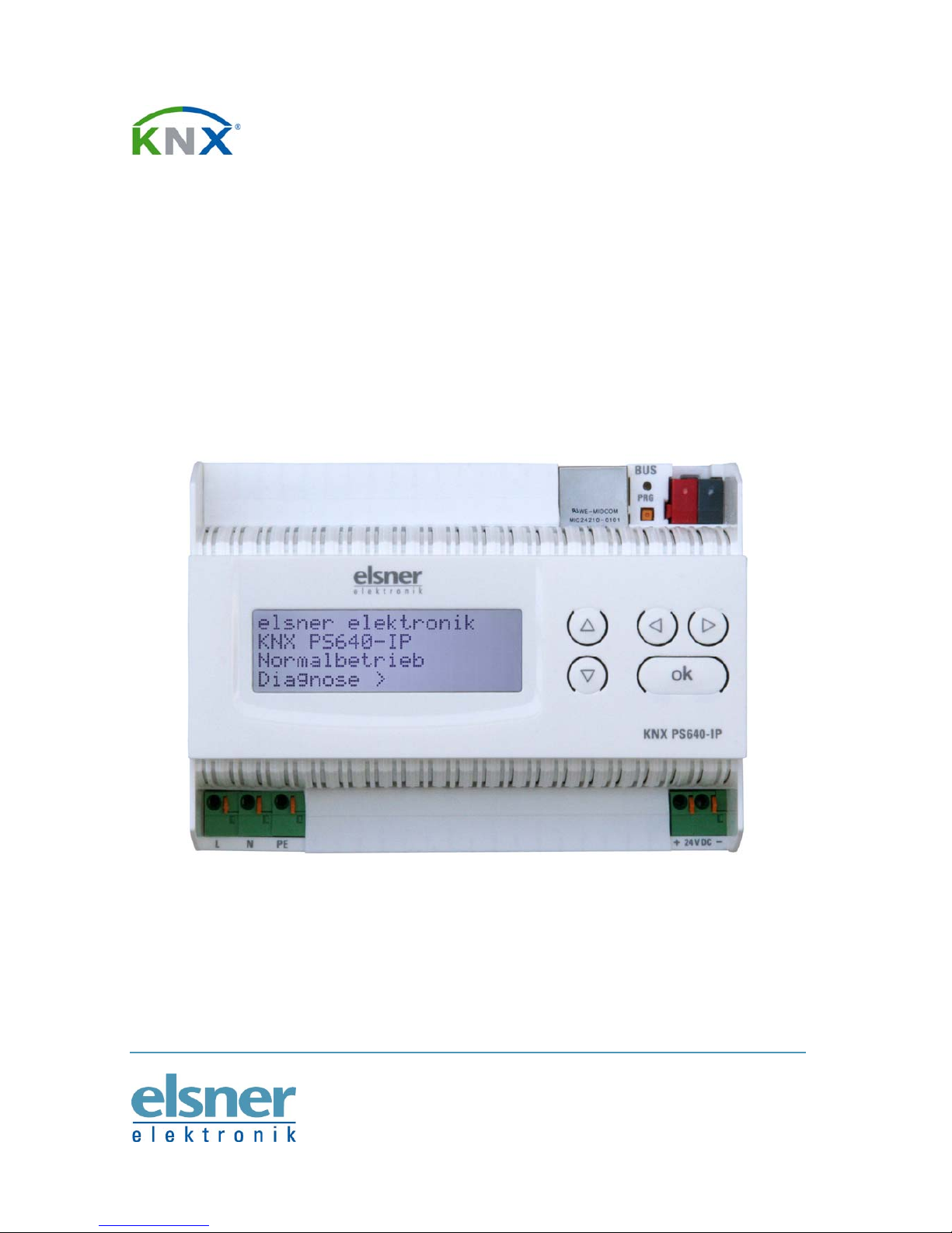
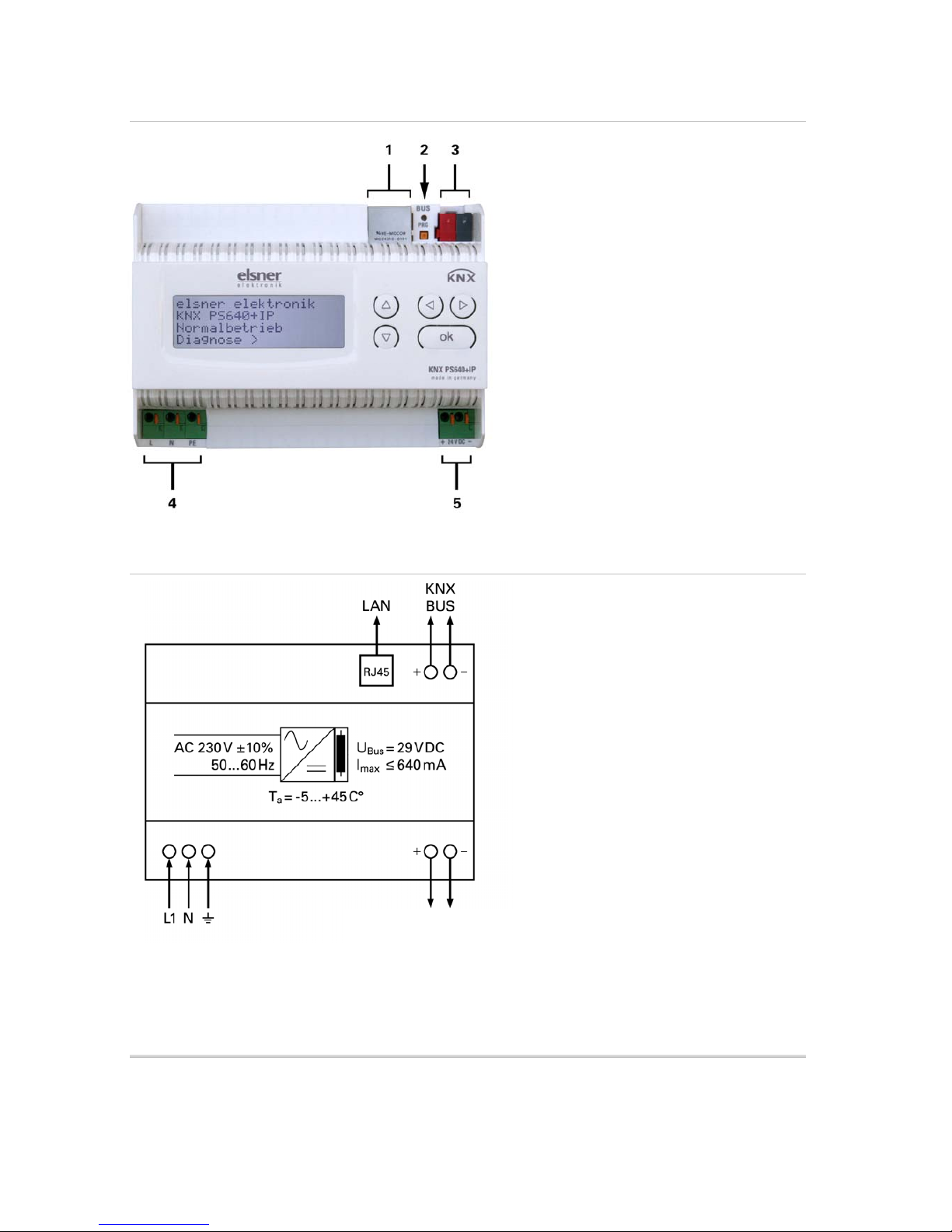
Housing
1 LAN connection (RJ45, for
Ethernet patch cable)
2 Programming LED and
programming button
3 Bus connection (KNX terminal
+ / -)
4 Input operating voltage 230 V
AC, L / N / PE
5 Output direct current voltage 24
V DC, + / Connections 4 and 5 are suitable for
solid conductors up to 1.5 mm² or
conductors with fine wires.
Scheme
KNX communication of IP interface and
power supply unit
The device has got two KNX interfaces, one for the “PLUS” functions of the power
supply unit and one for the IP router. The functions are registered at the bus separately
and parametrised in different product files (ETS).
Auxiliary Voltage 24 V DC
(max. 150 mA)

9
Addressing
IP interface and KNX power supply unit are addressed separately at the bus.
Addressing the IP interface
The IP interface is supplied with the bus address 15.15.0. You can program another
address in the ETS (product file of IP interface) by overwriting the 15.15.0 address or by
teaching via the programming key at the unit.
Addressing the KNX power supply unit
The power supply unit is supplied with the bus address 15.15.250. You can program
another address in the ETS (product file of power supply unit) by overwriting the
15.15.250 address or by using the “Prog. Mode” of the unit (see chapter Addressing the
power supply unit (programming mode)).
Settings in der ETS
Different product files are used for setting of the IP interface and the KNX functions of
the power supply unit.
Parametrise the IP interface
Use the product file of PS640-IP power supply unit, item number 70142.
For description of parameters please see manual, chapter Setting the IP interface in the
ETS.
Parametrise the KNX power supply unit
Use the product file of PS640+(USB) power supply unit, item numbers 70141, 70144.
For description of parameters please see manual, chapter Setting the bus functions of
the power supply unit in the ETS.
Settings at the device
Starting position
The following may be read off and set on the display of the Power Supply System KNX
PS640+IP:
Reset of a line
Recall of the data memory with operating hours, overcharge, external electrical
surge, internal electrical surge, short circuit and excess temperature
Recall of the operating data bus voltage, bus current and temperature
el
sner elektronik
KNX PS640+IP
Normal Operation
Diagnostics >
 Loading...