

Elsner KNX LW Series, KNX LW 70128, KNX LW 70129 Technical Specifications And Installation Instructions

EN
KNX LW
Brightness and Wind Sensor
Technical specifications and installation instructions
KNX LW 230 V
No. 7012 8
KNX LW 12...40 V DC / 12...28 V AC
Elsner Elektronik GmbH Control and Automation Engineering
Sohlengrund 16
75395 Ostelsheim Phone +49 (0) 70 33 / 30 945-0 info@elsner-elektronik.de
Germany Fax +49 (0) 70 33 / 30 945-20 www.elsner-elektronik.de
No. 70129


1 Contents
1. Description ........................................................................................... 3
1.1. Deliverables .............................................................................................................. 3
1.2. Technical specifications ........................................................................................... 3
2. Installation and commissioning ........................................................... 4
2.1. Installation notes ...................................................................................................... 4
2.2. Location ..................................................................................................................... 5
2.3. Mounting of the sensor ........................................................................................... 6
2.3.1. Attaching the mount ..................................................................................... 6
2.3.2. View of rear side and drill hole plan ........................................................... 7
2.3.3. Preparing the sensor .................................................................................... 8
2.3.4. PCB layout ..................................................................................................... 9
2.3.5. Mounting the weather station ................................................................... 10
2.4. Notes on mounting and commissioning .............................................................. 11
3. Addressing of the device at the bus .................................................. 12
4. Maintenance ....................................................................................... 12
5. Transmission protocol ....................................................................... 13
5.1. List of all communication objects ......................................................................... 13
6. Setting of parameters ........................................................................ 17
6.1. General settings ..................................................................................................... 17
6.2. Threshold values .................................................................................................... 17
6.2.1. Wind threshold value 1 / 2 / 3 .................................................................... 18
6.2.2. Brightness threshold value 1 / 2 / 3 ........................................................... 19
6.2.3. Twilight threshold value 1 / 2 / 3 ................................................................ 21
6.2.4. Logic ............................................................................................................ 22
6.2.5. AND Logic 1 / 2 / 3 / 4 / 5 / 6 / 7 / 8 .............................................................. 22
6.2.6. Linkage inputs of AND logic ...................................................................... 23
6.2.7. OR Logic 1 / 2 / 3 / 4 / 5 / 6 / 7 / 8 ................................................................ 24
6.2.8. Linkage inputs of OR logic ......................................................................... 24
Brightness and Wind Sensor KNX LW • from software version 1.02, ETS programme version 1.1
Elsner Elektronik GmbH • Sohlengrund 16 • 75395 Ostelsheim • Germany
Status: 19.07.2019. Technical changes and errors excepted.
2 Clarification of signs
Installation, inspection, commissioning and troubleshooting of the device
must only be carried out by a competent electrician.
This manual is amended periodically and will be brought into line with new software
releases. The change status (software version and date) can be found in the contents footer.
If you have a device with a later software version, please check
www.elsner-elektronik.de in the menu area "Service" to find out whether a more up-todate version of the manual is available.
Clarification of signs used in this manual
Safety advice.
Safety advice for working on electrical connections, components,
etc.
DANGER!
WARNING!
CAUTION!
ATTENTION!
ETS In the ETS tables, the parameter default settings are marked by
... indicates an immediately hazardous situation which will lead to
death or severe injuries if it is not avoided.
... indicates a potentially hazardous situation which may lead to
death or severe injuries if it is not avoided.
... indicates a potentially hazardous situation which may lead to
trivial or minor injuries if it is not avoided.
... indicates a situation which may lead to damage to property if it is
not avoided.
underlining.
3 Description
1. Description
The Brightness and Wind Sensor KNX LW measures the intensity of illumination
and wind speed and transfers the values to the KNX system. Nine switching outputs
with adjustable threshold values as well as additional AND and OR logic gates are
available. The sensor system, the evaluation electronics and the electronics of the bus
connection are mounted in a compact housing.
Functions:
• Brightness measurement: The current light intensity is measured by a
sensor
• Wind measurement: The wind strength measurement takes place
electronically and thus noiselessly and reliably, even during hail, snow and
sub-zero temperatures. Even turbulent air and anabatic winds in the vicinity of
the weather station are recorded
• 9 threshold values can be adjusted per parameter or via communication
objects
• 8 AND and 8 OR logic gates with each 4 inputs. Every switching incident as
well as 8 logic inputs (in the form of communication objects) may be used as
inputs for the logic gates. The output of each gate may optionally be configured
as 1 bit or 2 x 8 bits
Configuration is made using the KNX software ETS. The product file can be downloaded from the Elsner Elektronik website on www.elsner-elektronik.de in the “Service” menu.
1.1. Deliverables
• Sensor with combined wall/pole mounting
• 2x stainless steel installation band for pole installation
1.2. Technical specifications
Housing Plastic material
Colour White/translucent
Mounting On-wall
Protection category IP 44
Dimensions approx. 96 × 77 × 118 (W × H × D, mm)
Weight 230 V AC version approx. 240 g,
Ambient temperature Operation -30…+50°C, storage -30…+70°C
Operating voltage Available for 230 V AC or for 12...40 V DC (12...28 V AC)
Cable cross-section Massive conductors of up to 1.5 mm² or conductors
Brightness and Wind Sensor KNX LW • Status: 19.07.2019 • Technical changes reserved. Errors reserved.
12...40 V DC / 12...28 V AC version approx. 170 g
An appropriate power supply unit can be obtained from
Elsner Elektronik.
with fine wires

4 Installation and commissioning
Current
Data output KNX +/- bus terminal plug
BCU type Own micro controller
PEI type 0
Group addresses max. 254
Allocations max. 255
Communication objects 117
Measurement range Wind 0...35 m/s
Resolution (wind) 0,1 m/s
Accuracy (wind) at ambient temperature -20…+50°C:
Measurement range
brightness
Resolution (brightness) 1 lux up to 300 lux
Accuracy (brightness) ±15% of the measurement value at 30 lux … 30,000 lux
230 V AC version
12...40 V DC / 12...28 V AC version:
at 12 V DC max. 30 mA. max. 0,4 W.
residual ripple 10%
±22% of the measurement value when incident flow is
from 45…315°
±15% of the measurement value when incident flow is
from 90…270°
(Frontal incident flow corresponds to 180°)
0 lux … 150,000 lux
2 lux up to 1,000 lux
25 lux up to 150,000 lux
max. 20 mA,
The product conforms with the provisions of EU directives.
2. Installation and commissioning
2.1. Installation notes
Installation, testing, operational start-up and troubleshooting should
only be performed by an electrician.
DANGER!
Risk to life from live voltage (mains voltage)!
There are unprotected live components within the device.
• VDE regulations and national regulations are to be followed.
• Ensure that all lines to be assembled are free of voltage and take
precautions against accidental switching on.
Brightness and Wind Sensor KNX LW • Status: 19.07.2019 • Technical changes reserved. Errors reserved.
5 Installation and commissioning
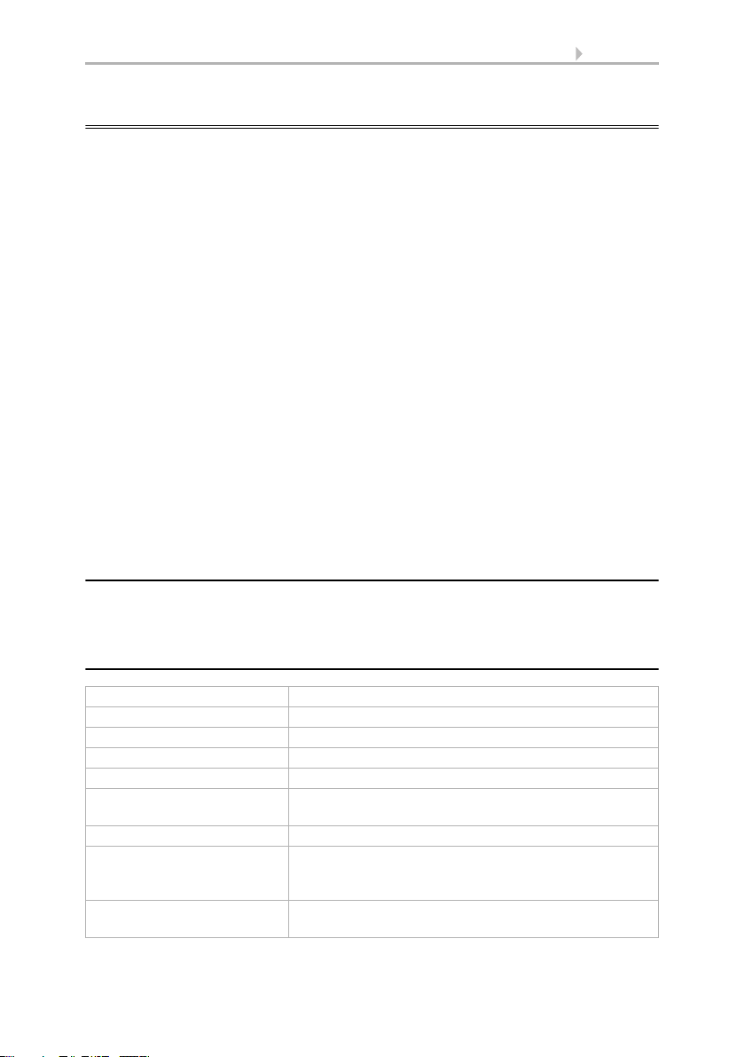
Fig. 1
There must be at least 60 cm of space below,
to the sides and in front of the sensor left
from other elements (structures, construction
parts, etc.).
60 cm
• Do not use the device if it is damaged.
• Take the device or system out of service and secure it against
unintentional use, if it can be assumed, that risk-free operation is no
longer guaranteed.
The device is only to be used for its intended purpose. Any improper modification or
failure to follow the operating instructions voids any and all warranty and guarantee
claims.
After unpacking the device, check it immediately for possible mechanical damage. If it
has been damaged in transport, inform the supplier immediately.
The device may only be used as a fixed-site installation; that means only when assembled and after conclusion of all installation and operational start-up tasks and only in
the surroundings designated for it.
Elsner Elektronik is not liable for any changes in norms and standards which may occur
after publication of these operating instructions.
2.2. Location
Select an assembly location at the building where sun and wind may be collected by
the sensors unobstructedly. The sensor may not be shaded by the building or for example by trees.
At least 60 cm of clearance must be left all round the device. This facilitates correct
wind speed measurement without eddies. The distance concurrently prevents spray
(raindrops hitting the device) or snow (snow penetration) from impairing the measurement. It also does not allow birds to bite it.
Brightness and Wind Sensor KNX LW • Status: 19.07.2019 • Technical changes reserved. Errors reserved.
6 Installation and commissioning
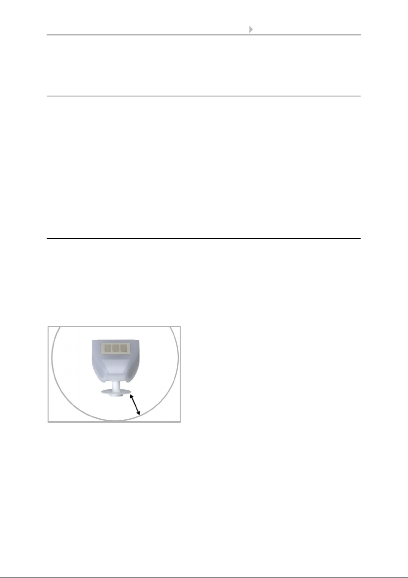
Fig. 2
The brightness/wind sensor must be mounted on a vertical wall (or a pole).
Wall
or
pole
Fig. 3
The brightness/wind sensor must be mounted in the horizontal transverse direction (horizontally).
Horizontal
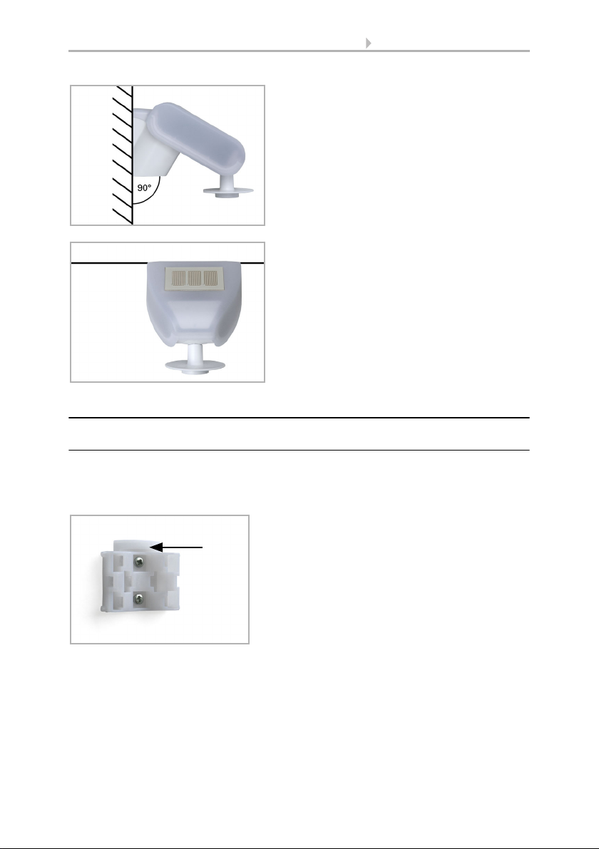
Fig. 4
When wall mounting: flat side on wall, crescentshaped collar upward.
Collar
2.3. Mounting of the sensor
2.3.1. Attaching the mount
The sensor comes with a combination wall/pole mount. The mount comes adhered by
adhesive strips to the rear side of the housing. Fasten the mount vertically onto the wall
or pole.
Brightness and Wind Sensor KNX LW • Status: 19.07.2019 • Technical changes reserved. Errors reserved.
7 Installation and commissioning
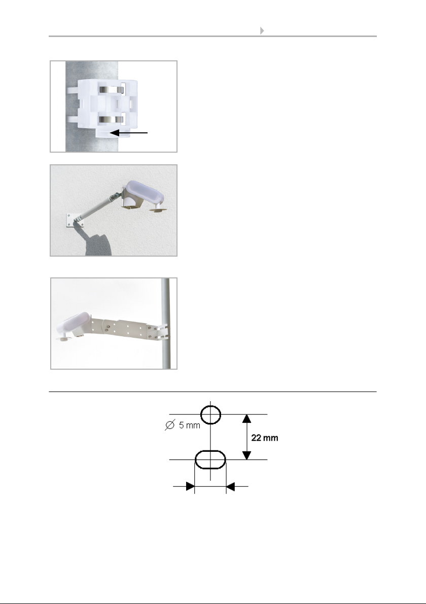
Fig. 5
When pole mounting: curved side on pole, collar
downward.
Collar
Fig. 6
Different mounting arms are available from Elsner Elektronik as additional, optional accessories
for flexible installation of the weather station on
a wall, pole or beam.
Example of the use of a mounting arm:
Due to flexible ball joints, the sensor can be
brought into ideal position.
Fig. 7
Example use of the hinge arm mounting:
Fitting to a pole with worm drive hose clips
Slot hole 7,5 x 5 mm
Fig. 8 a+b
Drill hole plan
Dimensions of rear side of
housing with bracket. Subject to change for technical
enhancement.
2.3.2. View of rear side and drill hole plan
Brightness and Wind Sensor KNX LW • Status: 19.07.2019 • Technical changes reserved. Errors reserved.
 Loading...