


Motor control unit
IMSG-UC-4H
Technical data
Elsner Elektronik GmbH Steuerungs- und Automatisierungstechnik
Herdweg 7 • D-75391 Gechingen • Germany
Phone: +49 (0) 70 56/93 97-0 • Fax: +49 (0) 70 56/93 97-20
info@elsner-elektronik.de • www.elsner-elektronik.de
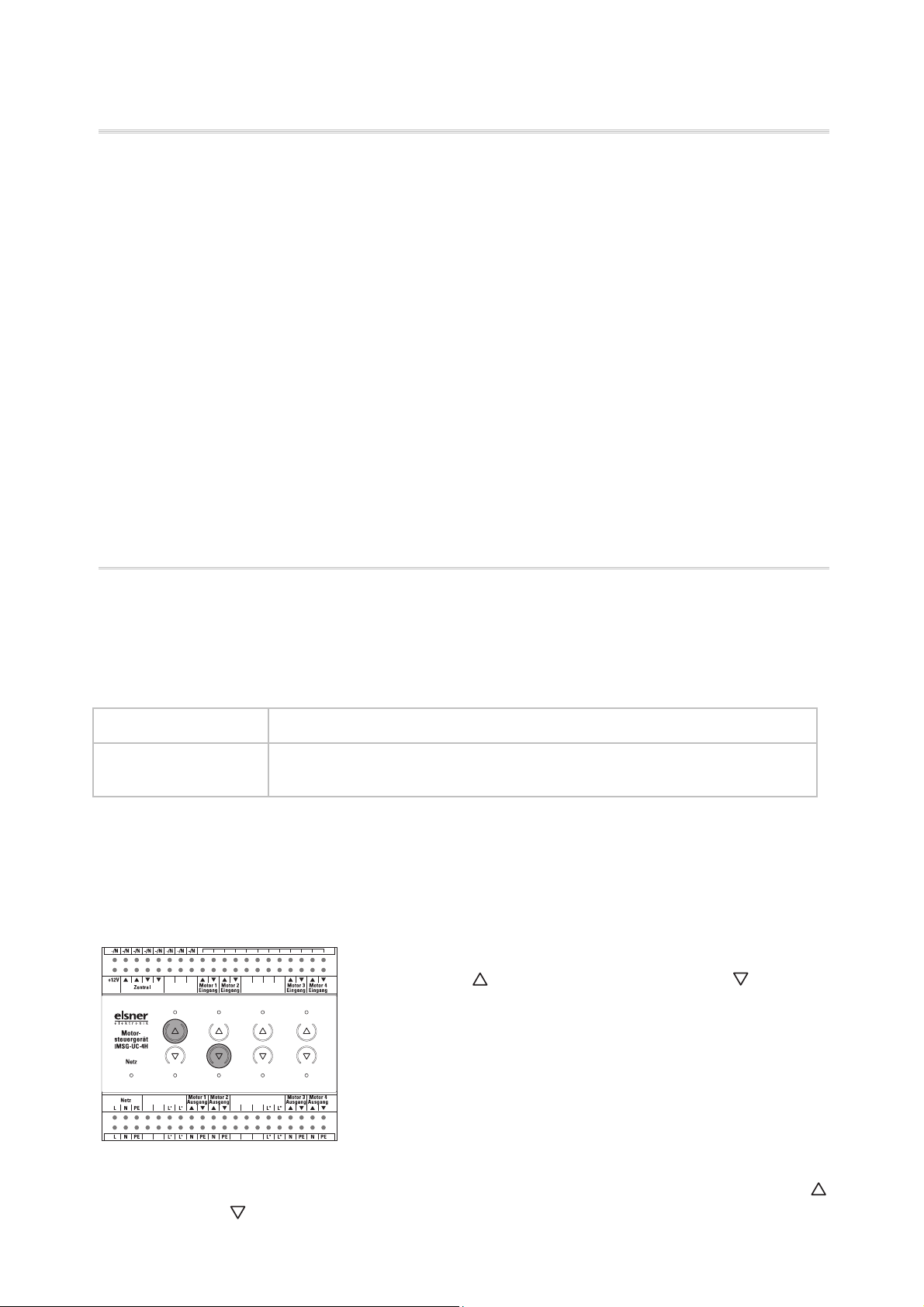
Product description
The IMSG-UC-4H motor control unit allows four 230V drives to be controlled. The unit
offers the possibility of operating the connected motors via integrated buttons or
manually via up/down hand switches.
Functions:
• For four 230V drives (Up/Down)
• With key pad (manual operation) and status LEDs
• 4 hand switch connections (extension inputs) for unlocked double button
(manual operation on the spot, can be set to Standard or Comfort mode)
• Central and extension inputs with variable voltage (6…80 V DC, 6…240 V AC)
• Setting the central control unit to “Deadman” or “Latch”
• Commands at the central and button inputs have the same priority
• Storing one movement position per drive
• Pause to reverse direction 1 second, motor runtime 240 seconds
• Connect through clamps
• Potential-free relays
Central operation
The central input of the IMSG-UC-4H allows, for example, an automatic control unit, a
timeswitch or a normal, unlocked double button (Up/Down) to be connected. The central
command (continuous voltage) always has priority over a movement command from the
extension inputs.
LED signals during central control (continuous voltage):
During movement: Channel LEDs in the direction of movement flash every 2 seconds
Runtime reached: Channel LEDs in the direction of movement continue to flash
every 2 seconds
If there are “Up” and “Down” movement commands at the central input at the same
time, the drive moves up (secure position).
The central control unit can be set to the operating modes “Latch” (default) or
“Deadman”. You can switch between the operating modes using the following buttons
integrated on the device:
Press the
button of channel 1 and the button
of channel 2 for 5 seconds at the same time
If the Latch mode is active, the Network LED is on. If the Deadman mode is active,
the Network LED flashes every second. Change the operating mode by pressing
(channel 1) and
2
Motor control unit IMSG-UC-4H • Status 30/06/2010 • Subject to technical changes. Errors excepted.
(channel 2) again.

Individual operation
Manual individual operation of the drives can take place via the integrated Up/Down
buttons at the device or via unlocked double buttons (extension inputs). The movement
mode can be stopped via both buttons (
movement.
LED signals during manual control:
During movement: Channel LED in the direction of movement flashes every second
or ), regardless of the current direction of
Runtime reached
LED for the direction travelled remains on
without interruption:
Intermediate position
LEDs off
reached:
Manual operation can be set to “Standard mode” or “Comfort mode”:
Standard mode (default)
• If a button is pressed for less than 1 second, the drive will move in a step-by-step
fashion. This allows, for example, slats to be positioned precisely.
• If a button is held for longer than 1 second, the drive moves to its final position
(switching off after 240 seconds of maximum runtime)
This is how you set the Standard mode:
• Press the
button on the channel to be set for 5 seconds and then additionally the
button for longer than 1 second
• To confirm the On LED on the channel flashes 5 times
Comfort mode:
• If a button is held for less than 0.3 seconds, the drive moves to its final position
(switching off after 240 seconds of maximum runtime)
• If a button is held for longer than 0.3 seconds, but less than 2 seconds, the drive
moves only while the button is pressed and stops immediately when it is released
(deadman function)
• If a button is held for longer than 2 seconds, the drive moves to its final position
(switching off after 240 seconds of maximum runtime)
This is how you set the Comfort mode:
• Press the
button on the channel to be set for 5 seconds and then additionally the
button for longer than 1 second
• To confirm the Off LED on the channel flashes 5 times
Individual movement position
The IMSG-UC-4H can store one movement position for each connected drive. This allows
fast and uncomplicated movement to a position that is needed often (e.g. a shutter
position or the partial opening of a window).
Motor control unit IMSG-UC-4H • Status 30/06/2010 • Subject to technical changes. Errors excepted.
3

Storing a movement position
Storing a position is carried out as follows:
• Move the drive to the starting/zero position, i.e. close the window, retract the
awning or raise the blinds
• Press the
and buttons for three seconds at the same time
• As feedback the drive moves briefly up and down. You are in now Programming
mode
• Move to the desired position
• Store the position by pressing the
and buttons for 1 second long at the same
time
• As feedback the drive moves briefly up and down
• With blind slats, now open the slats to the desired angle. With awnings, tighten the
canvas with
• Store by again pressing the
. For windows, you can skip this point.
and buttons for 1 second long at the same time
• As feedback the drive moves briefly up and down. The storage is complete and the
IMSG-UC-4H is again in normal mode
Note: As soon as a central command arrives (e.g. because of a wind or rain alarm), the
Programming mode will be interrupted! In this case, please carry out the position storage
again when the central command is no longer present.
Calling up a movement position
The stored position can be called up by pressing the button of the appropriate channel
for 3-6 seconds.
The drive will move to the movement position directly if it is in a secure position and the
runtimes of previous commands have expired. If the drive is in an intermediate position,
it will move initially to the secure position and then to the stored position after expiry of
the runtime.
Technical data
Housing: Plastic
Colour: White
Installation: Series installation on mounting rails
Protection rating: IP 20
Dimensions: approx. 107 x 88 x 60 (W x H x D, mm), 6 modules
Weight: approx. 360 g
Ambient temperature: Operation -20…+70°C, storage -55…+90°C
Ambient humidity: max. 95% rH, avoid dew
Auxiliary voltage: 230 V AC, 50 Hz
Inputs: • Central (Up/Down)
• 4 x hand switches (Up/Down buttons)
Outputs: • 4 x Drive 230 V (PE/N/Down/Up), each 4 A
4
Motor control unit IMSG-UC-4H • Status 30/06/2010 • Subject to technical changes. Errors excepted.

The following standards were used for assessing the product with regard to electromagnetic compatibility:
• EN 60730-1:2000-11 + A11:2002
The product was tested by an accredited EMC laboratory in accordance with the
abovementioned standards.
Installation and commissioning
Warning, mains voltage!
National legal regulations are to be observed.
Installation, testing, commissioning and fault repair of the motor control unit may only be
carried out by a qualified electrician. Shut off the voltage to all cables to be fitted and take
safety precautions against unintended activation.
The motor control unit is intended exclusively for appropriate use. Any improper
alteration or non-observance of the operating instructions will void any warranty or
guarantee claim.
After unpacking, the unit shall be checked immediately for any possible mechanical
damage. The supplier shall be immediately notified in the event of any transport damage.
The motor control unit must not be used if
damaged.
If it is assumed that danger-free operation can no longer be guaranteed, the equipment
shall be taken out of service and secured against unintended operation.
The motor control unit may only be operated as a fixed installation, meaning a built-in
condition and following the completion of all installation and commissioning work, and
only in the intended environment.
Elsner Elektronik shall not be liable for any changes to norms or standards after the
publication of these operating instructions.
Installation notes
Ensure that the unit does not come into contact with water: Even a few drops may
damage the electronics.
Ensure that the unit is correctly connected. An incorrect connection can lead to damage to
the motor control unit or to any electronic device connected to it.
Connection diagrams
When making connections please note:
• Mixing different control voltages for central and on-the-spot operation is not
permitted for IMSG-UC
• If two motor control units are switched in series behind one another (central
commands Up and Down are looped through), the -/N connections must be bridged
for equipotential bonding
Motor control unit IMSG-UC-4H • Status 30/06/2010 • Subject to technical changes. Errors excepted.
5

Control with 12V
6
Motor control unit IMSG-UC-4H • Status 30/06/2010 • Subject to technical changes. Errors excepted.

Control with 230V
Motor control unit IMSG-UC-4H • Status 30/06/2010 • Subject to technical changes. Errors excepted.
7

Connection example with several groups
For IMSG-UC-2H and/or -4H.
8
Motor control unit IMSG-UC-4H • Status 30/06/2010 • Subject to technical changes. Errors excepted.
 Loading...