

Elsner Corlo Touch KNX WL 70335, Corlo Touch KNX WL 70252, Corlo Touch KNX WL 70253, Corlo Touch KNX WL 70334, Corlo Touch KNX WL 70254 Installation And Operation Manual
...
EN
Corlo Touch KNX,
Corlo Touch KNX WL
Display and Touch Switch
Item numbers
Corlo Touch KNX WL 70252 (white / Chrome glossy), 70253 (black / Chrome glossy), 70254 (white / Chrome matt),
70255 (black / Chrome matt), 70334 (white / white matt), 70335 (black / black matt).
Corlo Touch KNX 70258 (white / Chrome glossy), 70259 (black / Chrome glossy), 70260 (white / Chrome matt),
70261 (black / Chrome matt), 70336 (white / white matt), 70337 (black / black matt)
Installation and Operation


1 Contents
1. Description ................................................... 5
1.1. Description ....................................................................................... 6
1.1.1. Deliverables .......................................................................................................... 7
1.1.2. Technical data ....................................................................................................... 7
1.1.3. Customizing options ............................................................................................ 8
Colors for edge and frame .................................................................................... 8
1.2. Installation and start-up ................................................................... 9
1.2.1. Installation notes .................................................................................................. 9
1.2.2. Installation ............................................................................................................. 9
Assembly site and assembly preparations ......................................................... 9
Assembling the frame and the display unit ...................................................... 10
Connection overview .......................................................................................... 12
1.2.3. Instructions for assembly and operational start-up ........................................ 12
1.3. Addressing the device .................................................................... 13
1.4. Setting up the WLAN connection ................................................... 13
1.4.1. WLAN settings in the ETS .................................................................................. 13
1.4.2. Displaying WLAN status on the display ........................................................... 13
1.5. Maintenance and care ..................................................................... 14
1.6. Load individual images ................................................................... 14
1.6.1. Images for screensaver ...................................................................................... 14
1.6.2. Images for image display .................................................................................. 15
1.6.3. Exchanging images and graphics ..................................................................... 15
1.7. Connection/control options ............................................................ 16
1.7.1. An overview of the automatic functions .......................................................... 16
1.7.2. Overview of functions ........................................................................................ 18
1.8. List of communications objects ..................................................... 19
2. System settings via ETS ............................. 33
2.1. Basic configuration in the ETS ....................................................... 34
2.2. System language ............................................................................. 35
2.3. Editable text language .................................................................... 36
2.4. Display ............................................................................................ 37
2.5. Ambient lighting ............................................................................. 39
2.6. Button tone ..................................................................................... 41
2.7. Proximity sensor ............................................................................. 42
2.8. Alarm .............................................................................................. 42
2.9. Weekly timer ................................................................................... 43
2.9.1. Periods 1 ... 16 ..................................................................................................... 44
2.10. Alarm .............................................................................................. 45
2.11. Service ............................................................................................ 46
Elsner Elektronik GmbH • Sohlengrund 16 • 75395 Ostelsheim • Germany
Display Corlo Touch KNX • from KNX-Firmware 0.3.7 • ETS Version 2.0
Version: 09.03.2017 • Subject to technical changes. Errors excepted.

2 Contents
3. System settings via touch display ............. 49
3.1. Access codes for display menus ..................................................... 50
3.2. System language ............................................................................. 51
3.3. Editable text language .................................................................... 52
3.4. Display ............................................................................................ 52
3.4.1. Cleaning mode .................................................................................................... 52
3.4.2. Screen options .................................................................................................... 53
3.4.3. Brightness ........................................................................................................... 53
3.4.4. Screen saver ....................................................................................................... 55
3.4.5. Start display ........................................................................................................ 57
3.4.6. No-touch action .................................................................................................. 58
3.5. Ambient lighting ............................................................................. 58
3.5.1. Brightness ........................................................................................................... 59
3.5.2. Colour .................................................................................................................. 61
3.6. Button tone ..................................................................................... 62
3.7. Alarm .............................................................................................. 64
3.8. Timer ............................................................................................... 66
3.9. Alarm .............................................................................................. 67
3.10. Service ............................................................................................ 70
3.10.1. Reset the access code ........................................................................................ 70
3.10.2. Reset the system to the status of the last ETS download ............................... 70
3.10.3. Device reset ......................................................................................................... 70
3.10.4. Addressing the equipment ................................................................................ 71
3.10.5. Info ....................................................................................................................... 71
3.10.6. License ................................................................................................................. 71
4. Set up display screens ............................... 73
4.1. Select screen on display ................................................................. 74
4.2. Setting up screens in the ETS ......................................................... 74
Area ...................................................................................................................... 75
Rocker ................................................................................................................... 77
Rotary control ...................................................................................................... 78
4.2.1. Overview predefined screens ............................................................................ 81
4.2.2. Symbol overview ................................................................................................ 87
5. Automatic functions .................................. 95
Safety notes for automatic functions ................................................................. 96
5.1. General automation settings .......................................................... 96
5.1.1. Allocate automation ........................................................................................... 97
5.1.2. Sun position ........................................................................................................ 97
Elsner Elektronik GmbH • Sohlengrund 16 • 75395 Ostelsheim • Germany
Display Corlo Touch KNX • from KNX-Firmware 0.3.7 • ETS Version 2.0
Version: 09.03.2017 • Subject to technical changes. Errors excepted.

3 Contents
5.1.3. Adapt parameters ............................................................................................... 99
General automation settings .............................................................................. 99
Wind alarm ........................................................................................................... 99
Twilight ............................................................................................................... 100
Travel delays ...................................................................................................... 100
Windows opening limitation ............................................................................ 100
Ventilation lock .................................................................................................. 101
Night-time re-cooling ........................................................................................ 101
Frost alarm ......................................................................................................... 101
Heat protection .................................................................................................. 102
Automatic Reset ................................................................................................ 102
5.2. Automatic light mode ................................................................... 103
5.3. Shade automation (shutters, awnings, blinds) ............................. 104
5.3.1. Set bus communication ................................................................................... 104
5.3.2. Changing basic parameters ............................................................................. 106
5.3.3. Setting the blind automation ........................................................................... 106
Setting the shading ........................................................................................... 107
Sun position angle ............................................................................................ 112
5.4. Automatic window mode .............................................................. 112
5.4.1. Set bus communication ................................................................................... 112
5.4.2. Changing basic parameters ............................................................................. 113
5.4.3. Setting the window automation ...................................................................... 114
Setting the window ventilation ........................................................................ 114
5.5. Automatic fan mode ..................................................................... 117
5.5.1. Set bus communication ................................................................................... 117
5.5.2. Changing basic parameters ............................................................................. 117
5.5.3. Setting the automatic ventilation .................................................................... 118
Ventilation settings ............................................................................................ 118
5.6. Temperature controller ................................................................. 120
General regulation ............................................................................................. 120
General set point values ................................................................................... 122
Heating control level 1/2 ................................................................................... 125
Cooling control level 1/2 ................................................................................... 127
6. Additional settings (ETS) ......................... 131
6.1. Interfaces ...................................................................................... 132
6.1.1. Interface 1-4 ...................................................................................................... 132
Control modes for drive control ....................................................................... 135
6.2. Temperature threshold values ...................................................... 136
6.2.1. Threshold values 1-4 ........................................................................................ 137
6.3. Scenario control ........................................................................... 138
6.3.1. Scene objects 1 - 16 .......................................................................................... 139
6.4. Logic (ETS) .................................................................................... 139
6.4.1. AND logic outputs 1/2/3/4 and OR logic outputs 1/2/3/4 ............................... 140
Elsner Elektronik GmbH • Sohlengrund 16 • 75395 Ostelsheim • Germany
Display Corlo Touch KNX • from KNX-Firmware 0.3.7 • ETS Version 2.0
Version: 09.03.2017 • Subject to technical changes. Errors excepted.

4 Clarification of signs
Installation, inspection, commissioning and troubleshooting of the device
must only be carried out by a competent electrician.
This manual is amended periodically and will be brought into line with new software
releases. The change status (software version and date) can be found in the contents footer.
If you have a device with a later software version, please check
www.elsner-elektronik.de in the menu area "Service" to find out whether a more up-todate version of the manual is available.
Clarification of signs used in this manual
Safety advice.
Safety advice for working on electrical connections, components,
etc.
DANGER!
WARNING!
CAUTION!
ATTENTION!
ETS In the ETS tables, the parameter default settings are marked by
... indicates an immediately hazardous situation which will lead to
death or severe injuries if it is not avoided.
... indicates a potentially hazardous situation which may lead to
death or severe injuries if it is not avoided.
... indicates a potentially hazardous situation which may lead to
trivial or minor injuries if it is not avoided.
... indicates a situation which may lead to damage to property if it is
not avoided.
underlining.

5 Description
1. Description
Display Corlo Touch KNX • Status: 09.03.2017 • Technical changes and errors reserved.

6 Description
1.1. Description
The Display Corlo Touch KNX for the KNX system offers a variety of options for its
use: Its touch-sensitive glass interface means that it can be used as a normal switch.
The high resolution display is ideal for displaying text, images or graphics. In addition
to current readings and messages, the KNX bus system can also display photographs,
for example. Concurrently, you can set up the Corlo Touch KNX as a control center
for automatic shading, ventilation and air conditioning regulation.
With the Corlo Touch KNX WL model, you can also show network content on the
display using the WLAN connection, e.g. web pages, IP camera images or
visualizations. The Corlo Touch KNX WL display screen can, for example, be shown on
a Smartphone, if a VPN connection is provided externally.
Functions:
• 3.5" touch-sensitive interface
• 10 display pages, which can be configured with different areas for control or
display purposes, for example switches, buttons, rocker switch, rotary knob,
readings
With the Corlo Touch KNX WL model, you can display predefined web pages
using the WLAN connection. You enter URL addresses in the ETS
• Icons for display can be exchanged (symbol library in the device, own pictures
from by micro SD card)
• Ambient lighting with individually variable colors (RGB)
•Integrated proximity sensor. Enables proximity switching and fast activation
of the display from standby mode
•Integrated brightness sensor for automatic adjustment of the display lighting
• Integrated scene control(16 scenes), timer, alarm clock
• 5 automatic channels , integrated automation for ventilation (windows,
ventilation equipment), for shading (shutter, blinds, awning) for air
conditioning regulation (heating, cooling) and for light
• 4 AND and 4 OR logic gates each with 4 inputs. 16 logic inputs (in the form
of communication objects) are available as inputs for the logic gates.
The output of each gate can be optionally configured as 1-bit or 2 x 8-bit
• 4 inputs for binary contact or temperature sensor
• Micro SD card socket e.g. as storage for image data
• USB interface
• Corlo Touch KNX WL model: WLAN interface for wireless data transfer
from or into local networks
Configuration is made using the KNX software ETS. The product file can be
downloaded from the Elsner Elektronik website on www.elsner-elektronik.de in the
“Service” menu.
Display Corlo Touch KNX • Status: 09.03.2017 • Technical changes and errors reserved.

7 Description
1.1.1. Deliverables
• Display unit
• Connection line
You will also require (not included in deliverables):
• Corlo frame (available as a single, dual, or triple frame)
Optional accessories:
(not included in the deliverables):
• T-NTC temperature sensor (No. 30516)
• Micro SD card for image data (off the shelf)
1.1.2. Technical data
Housing Glass: real glass, tempered
Display Visible diagonal: 3,5 inches
Colors • White glass, bright chromed edge
Assembly Flush mounting
Dimensions Housing overall approx. 80 × 71 × 49 (W × H × D, mm),
Weight display unit
Corlo Touch KNX
Weight display unit
Corlo Touch KNX WL
Weight frame frame 1-gang approx. 75 g,
Ambient temperature Operation 0...+50°C, storage -10...+50°C
Ambient humidity max. 95% RH, avoid condensation
Operating voltage 24 V DC ±10%
Edge: zinc pressure die casting
Housing: plastic
Resolution: 320 × 240 pixel
Viewing Angle: 6 o’clock viewing direction
Opening angle x: -75° to +75° typ.
Opening angle y: -55° to +75° typ.
• White glass, matt chromed edge
• Black glass, bright chromed edge
• Black glass, matt chromed edge
• White glass, edge matt white
• Black glass, edge matt black
• Custom colors on request (see
Colors for edge and frame, Page 8)
(Wall installation in junction box
Mounting depth approx. 12.5 mm
approx. 140 g
approx. 160 g
frame 2-gang approx. 95 g,
frame 3-gang approx. 115 g
Ø 60 mm)
Display Corlo Touch KNX • Status: 09.03.2017 • Technical changes and errors reserved.
8 Description
Power consumption
Corlo Touch KNX
Power consumption
Corlo Touch KNX WL
Data output/
bus communication
BCU type unit's own microcontroller
PEI type 0
Group addresses max. 1024
Assignments max. 1024
Communication objects 1022
Other data interfaces Micro SD, USB
Inputs 4× Analog/digital,
Setting range of
temperature sensor T-NTC
at input of Corlo Touch
• approx. 1.3 W maximum (when ambient and logo
lighting 100% white, display brightness 100%)
• approx. 0.9 W in normal operation (when ambient
and logo lighting off, display brightness 50%)
• approx. 0.6 W in standby operation (when ambient
and logo lighting off, display off)
(was measured with 24 V auxiliary voltage)
• approx. 3.5 W maximum (when ambient and logo
lighting 100% white, display brightness 100%)
• approx. 1.9 W in normal operation (when ambient
and logo lighting off, display brightness 50%)
• approx. 1.7 W in standby operation (when ambient
and logo lighting off, display off)
(was measured with 24 V auxiliary voltage)
KNX +/- Bus connector terminal
max. cable length 10 m
-40°C...+80°C
The product conforms with the provisions of EU guidelines.
1.1.3. Customizing options
Colors for edge and frame
The standard colors for the display edge and matching frame are matt chrome and
bright chrome. Special paints are possible, e. g. to RAL or automobile paint color
codes. Please ask for your desired color.
The glass pane is only available with white or black painting, special colours are not
possible.
Display Corlo Touch KNX • Status: 09.03.2017 • Technical changes and errors reserved.
9 Description
1.2. Installation and start-up
1.2.1. Installation notes
Installation, testing, operational start-up and troubleshooting should
only be performed by an electrician.
CAUTION!
Live voltage!
There are unprotected live components inside the device.
• National legal regulations are to be followed.
• Ensure that all lines to be assembled are free of voltage and take
precautions against accidental switching on.
• Do not use the device if it is damaged.
• Take the device or system out of service and secure it against
unintentional use, if it can be assumed, that risk-free operation is no
longer guaranteed.
The device is only to be used for its intended purpose. Any improper modification or
failure to follow the operating instructions voids any and all warranty and guarantee
claims.
After unpacking the device, check it immediately for possible mechanical damage. If it
has been damaged in transport, inform the supplier immediately.
The device may only be used as a fixed-site installation; that means only when
assembled and after conclusion of all installation and operational start-up tasks and
only in the surroundings designated for it.
Elsner Elektronik is not liable for any changes in norms and standards which may occur
after publication of these operating instructions.
1.2.2. Installation
Assembly site and assembly preparations
The device must only be installed and operated in dry, indoor
spaces. Avoid condensation.
ATTENTION!
The WLAN range for the Corlo Touch KNX WL model can be
reduced as a result of the position where it is installed.
Consider this when planning the location.
Display Corlo Touch KNX • Status: 09.03.2017 • Technical changes and errors reserved.
10 Description
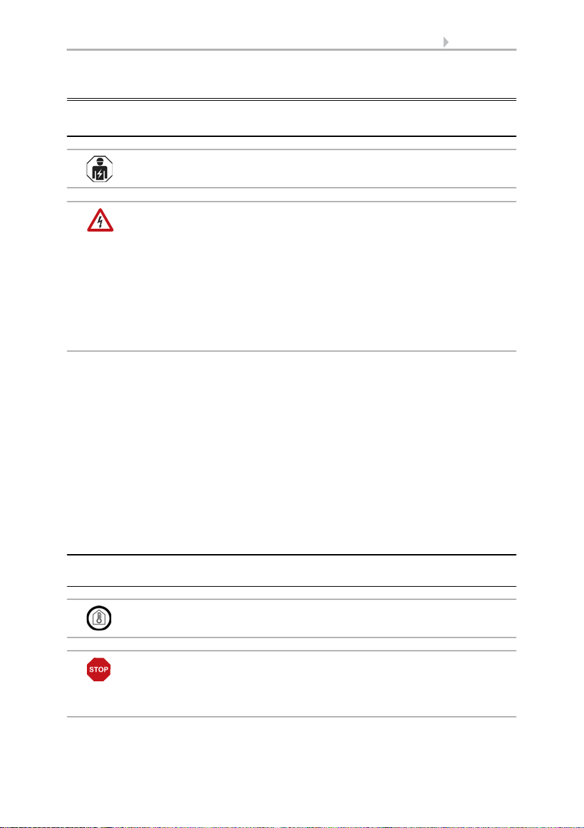
Fig. 1: Sectional drawing.
The Display Corlo Touch KNX fits in a normal
junction box (R 60 mm, depth 42 mm).
If the analog/digital inputs are used, a deep
socket (60 mm) or an electronics socket should be
used. In this way, cables can be connected and
stowed more conveniently.
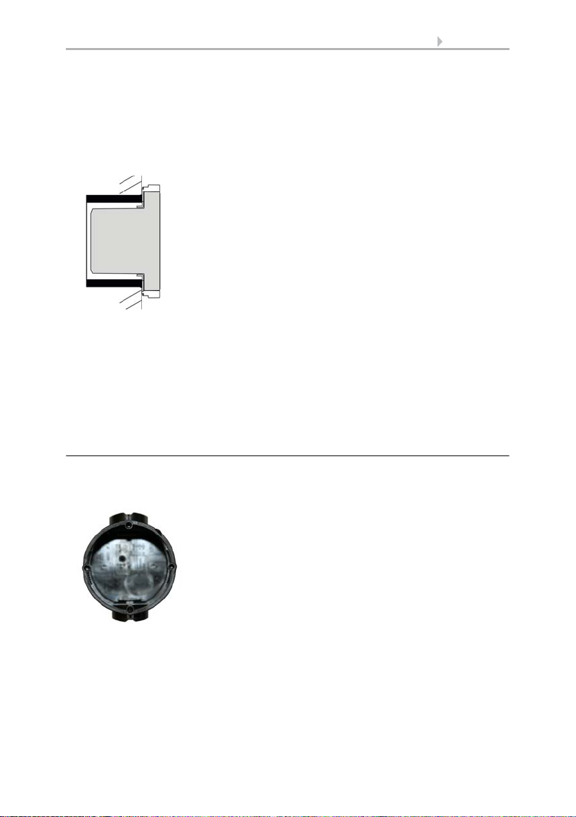
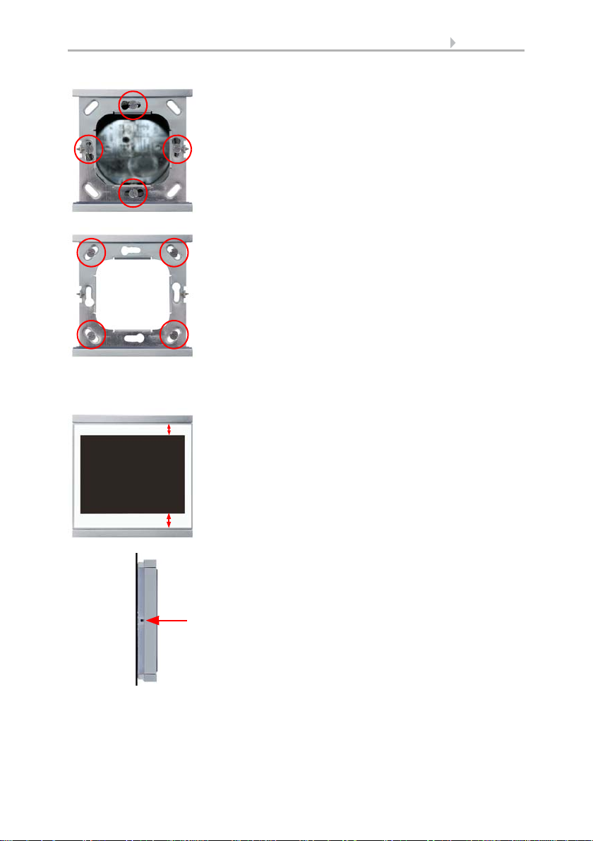
Fig. 2
A socket with 4 screw domes faciliates
installation.
Avoid direct light (sunlight, lights) when choosing the assembly site. The proximity
sensor's function can be impaired by strong light sources.
Choose the assembly height based on the application in each case: When used as a
switch, the Corlo Touch KNX should be mounted 110 cm above ground level and
when used as an indicating and control display, at a conveniently legible height, say
150 cm.
When using a dual or triple frame, two or three sockets with a separation of 71 mm
must be placed accordingly. The frames must be installed vertically.
Overall dimensions with frame:
Single, approx. 80 mm x 81 mm (W x H),
Dual, approx. 80 mm x 153 mm (W x H),
Triple, approx. 80 mm x 224 mm (W x H),
Mounting depth approx. 12.5 mm
Assembling the frame and the display unit
The instructions show installation of display unit with a single frame. Dual and triple
frames are installed accordingly.
Display Corlo Touch KNX • Status: 09.03.2017 • Technical changes and errors reserved.
11 Description
Fig. 3
Bolt the frame on to the socket. Two screws
(right/left or top/bottom) are enough.
Fig. 4
If the screw domes of the box used are not
covered with the frame's longitudinal holes,
the frame can alternatively be bolted via the four
outside holes (e.g. for boxes from Swiss systems
or other installation systems).
Fig. 5
The display unit can now be put in place.
The wider part of the display edge must
be at the bottom.
The display unit engages on the right and left
sides and is also held by magnets.
Fig. 6
To remove the display unit from the frame, press
one of the snaplock connections on the side of
the device with a pointed instrument. You can
now pull the device to the front at the unlocked
side und remove it.
Wall
Connect KNX bus, auxiliary voltage und where required the connection line inputs to
the display unit.
Display Corlo Touch KNX • Status: 09.03.2017 • Technical changes and errors reserved.
12 Description
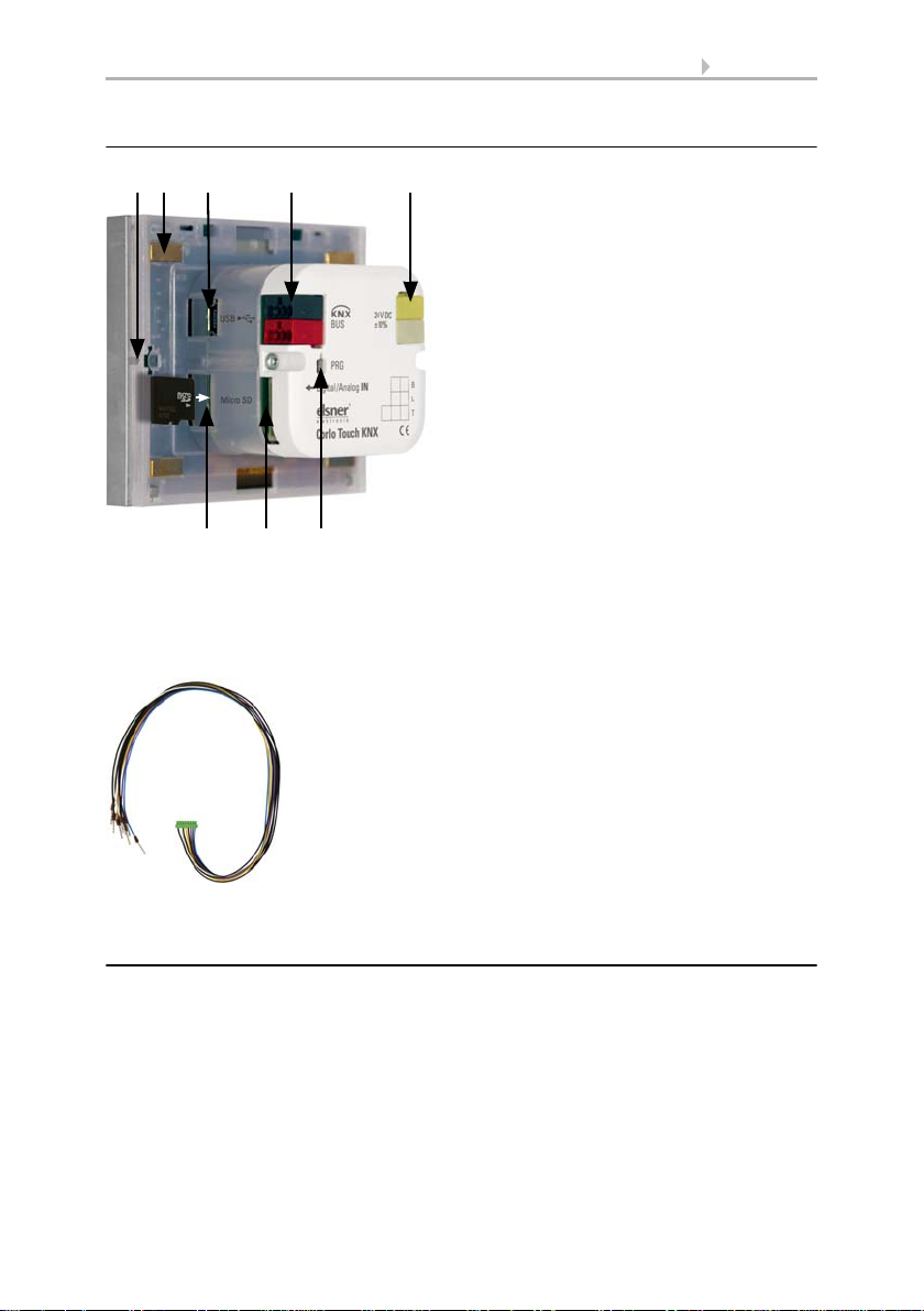
Fig. 7
1 Snaplock connector seating
2 Magnets (additional fixing)
3 USB socket
4 KNX terminal bus +/5 Terminal auxiliary supply 24 V DC
±10%, terminal configuration
independent from polarity
6 Micro SD socket (card contacts must
show in the direction of the display
when inserting it)
7 Analog/digital inputs socket
8 Programming button for addressing
the device at the bus (recessed)
2 34 51
678
Fig. 8
Breakout cable for analog/digital inputs:
Input 1: black/white
Input 2: black/yellow
Input 3: black/lilac
Input 4: black/blue
Connection overview
Connect the bus voltage (no. 4, red/black terminals) and auxiliary voltage (no. 5,
yellow/white terminals). Use the attached breakout cable for connecting the digital/
analog inputs (no. 7). The cables for the inputs can be extendet to up to 10 m. All GND
connections of the inputs are bridged internally (black cable).
1.2.3. Instructions for assembly and operational start-up
Never expose the sensor to water (e.g. rain) or dust. This can damage the electronics.
You must not exceed a relative air humidity of 95%. Avoid condensation.
After the operating voltage has been applied, the device will enter an initialisation
phase lasting a few seconds. During this phase no information can be received or sent
via the bus.
Display Corlo Touch KNX • Status: 09.03.2017 • Technical changes and errors reserved.
13 Description
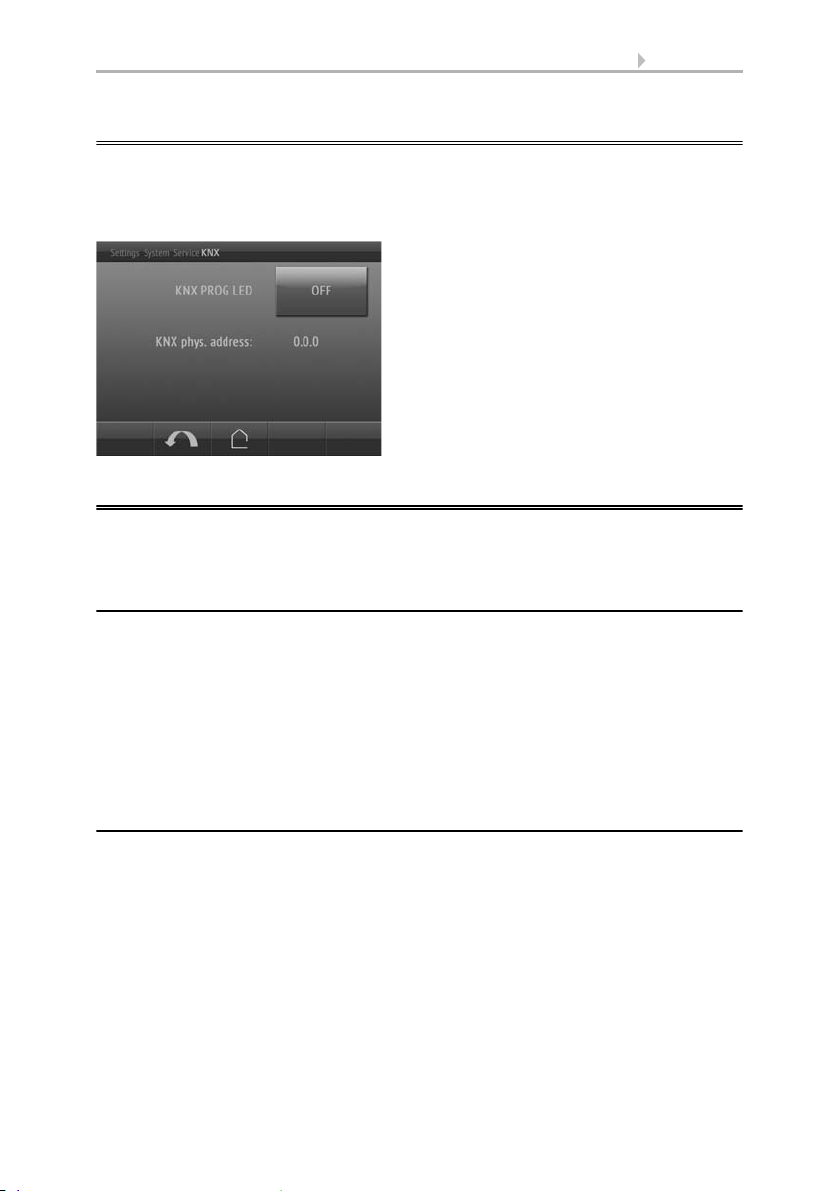
KNX programmming LED ON:
Programming mode active.
KNX programming LED OFF:
Programming mode off.
The current address is displayed (Address
15.15.250 when delivered).
1.3. Addressing the device
The programming mode for addressing at the bus is activated via the programming
button at the back of the housing or via the display.
Settings > System > Service > KNX
1.4. Setting up the WLAN connection
Only for the Corlo Touch KNX WL model with an interface for wireless network
connection!
1.4.1. WLAN settings in the ETS
The WLAN connection must be set up in the ETS. Consult the WLAN setting section in
the manual
ETS: System Settings > WLAN
2.13.1 WLAN
You set the network name and the encryption for compatibility with the WLAN network
access point. The IP address allocation can be made either automatically by DHCP or
manually.
1.4.2. Displaying WLAN status on the display
You can call up information on the current status of the connection on the Corlo
Touch KNX display. Network name, signal strength, IP address, DNS address and GW
address are displayed.
Settings > System > Service > WLAN Status
3.11.7. WLAN Status
Display Corlo Touch KNX • Status: 09.03.2017 • Technical changes and errors reserved.
14 Description
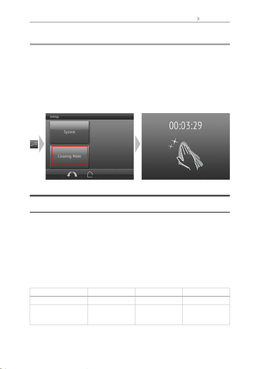
1.5. Maintenance and care
Fingerprints on the glass area and frame are best removed with a cloth moistened with
water or a microfiber cloth. Do not use an abrasive cleaning agent or aggressive
cleansing agents.
For cleaning of the screen, the „cleaning mode“ can be used, that is activeted via the
display.
Settings > Cleaning Mode
During a period set in the ETS, the touch function is disabled then and the screen can
be cleaned.
1.6. Load individual images
1.6.1. Images for screensaver
The setting of the screen saver is described in the manual chapters
2.4. Display (ETS) and 3.4.4. Screen saver (Display)
Images that are shown as the screensaver must be stored on a micro SD card. In order
that the system can recognize the SD card, carry out a reset in the menu after inserting
it
Settings> System > Reset
This is not necessary if the card was inserted before booting the system. The card must
remain in the device.
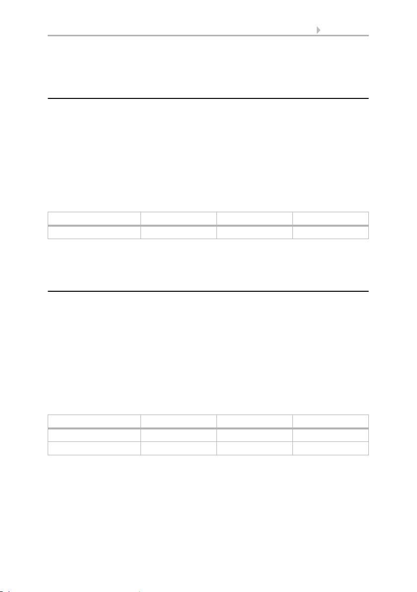
Store images in the given size in a corresponding folder on the top level of the SD card:
Image type Resolution File format Folder name
Images for slide show 320 × 240 pixels .jpg (RGB mode) slideshow
Images for
individual image
display
Display Corlo Touch KNX • Status: 09.03.2017 • Technical changes and errors reserved.
320 × 240 pixels .jpg (RGB mode) diafix
15 Description
Images for individual image display ("diafix" folder) must have a 4-digit numerical
sequence so that they can be called up in the ETS and in the menu (0001...9999).
1.6.2. Images for image display
Images can be called up as a stationary display (e. g. welcome screen). In contrast to
the screensaver, the touch function is disabled while a stationary image is displayed.
Images that are to be called up via the "Stationary Image" communication object must
be stored on a micro SD card. In order that the system can recognize the SD card, carry
out a reset in the menu after inserting it
Settings> System > Reset
This is not necessary if the card was inserted before booting the system. The card must
remain in the device.
Store images in the given size in a corresponding folder on the top level of the SD card:
Image type Resolution File format Folder name
Stationary images 320 × 240 pixels .jpg (RGB mode) festbilder
Stationary images must have a 4-digit numerical sequence so that they can be called
up in the ETS and in the menu (0001...9999).
1.6.3. Exchanging images and graphics
For the Corlo Touch KNX display pages, a large number of icons from the area of
security, multimedia, sensors, operation, house, light and air conditioning and drive
control are available and these are stored in the device. However, you can also use
proprietary symbol graphics and rotary control graphics.
Images that are shown as icons must be stored on a micro SD card. In order that the
system can recognize the SD card, carry out a reset in the menu after inserting it
Settings> System > Reset
This is not necessary if the card was inserted before booting the system. The card must
remain in the device.
Store images in the given size in a corresponding folder on the top level of the SD card:
Image type Resolution File format Folder name
Symbol/small icon 48 × 48 pixels .png icons
Icons for rotary control 158 × 158 pixels .png icons
Icons must have a 4-digit numerical sequence so that they can be called up in the ETS
and in the menu (0001...9999).
Display Corlo Touch KNX • Status: 09.03.2017 • Technical changes and errors reserved.

16 Description
1.7. Connection/control options
For the automatic control of shading, ventilation etc., several different ambient
parameters/measuring values must be provided via the bus. Chapter An overview
of the automatic functions, Page 16 contains a list of the parameters needed for the
individual automatic functions.
A temperature sensor to capture the room temperature may also be directly connected
to one of the 4 analogue/digital input of the device. Those inputs may also be used
to connect conventional buttons, switches and window contacts.
Date and time should be received at least once a day via the bus (objects no. 7 or
8+9). Object no. 10 serves to request the date and time. The internal device clock
deviates max. ±3 seconds per day. The alarm function of the Corlo Touch KNX is
only active after the current time has been received from the bus.
1.7.1. An overview of the automatic functions
The Display Corlo Touch KNX has five automatic channels which may be dedicated
to the functions, light, awning, shutter, blind, window, ventilation device and
temperature control (heating/cooling).
General instructions:
• The entire runtime is completed for timed closures (no movement position)
• The movement positions are only settable in the shading and ventilation areas
Lighting:
In order to control the lighting, the ambient parameters/measuring values
•Brightness
•Time
are needed.
• Switching or dimming For dimming, the brightness can be set for ON/OFF.
• Switching on at night and in regular periods. Both may also be combined (AND/
OR). The twilight value is adjustable.
• Automatic resets (time/periods can be set)
Shutters, awnings, blinds:
In order to control the shading, the ambient parameters/measuring values
•Brightness
• Sun position
• Outdoor temperature
• Indoor temperature
•Wind speed
• Precipitation warning
•Time
are needed.
Display Corlo Touch KNX • Status: 09.03.2017 • Technical changes and errors reserved.

17 Description
• Shading dependent on brightness and position of the sun (sun elevation and
direction)
or all the time (privacy, i.e. modification of slat and movement position only)
or never (only close at night/at set times, protection against rain, wind and
frost).
• Movement position and slat position can be set in two degrees. Slat retraction
dependent on sun elevation possible
• Travel delays during extension/retraction can be set
• Night-time closure
• Timed closure
• Interior temperature block: Leave open until a selected interior temperature is
reached
• Outdoor temperature block: Shading active only once a pre-set outdoor
temperature is exceeded
• Heat protection (alternative movement position)
• Frost protection (retraction when precipitation below a pre-set outdoor
temperature)
• Wind protection (retraction when a pre-set wind speed is exceeded)
• Rain protection (retraction during precipitation)
• Automatic resets (time/periods can be set)
Window
In order to control the windows, the ambient parameters/measuring values
• Outdoor temperature
• Indoor temperature
• Indoor air humidity
• CO2 content of indoor air
•Wind speed
• Precipitation warning
•Time
are needed.
• Graded opening with up to 10 levels
• Movement position/opening limitation
• Ventilation based on indoor temperature, air humidity and room air CO2
content
• Outdoor temperature block: Block when below a selected outdoor temperature
• Frost protection: Retraction when precipitation below a pre-set outdoor
temperature
• Close when the supply air temperature is higher than the room temperature
• Rain protection: Close completely or to only provide a gap during rainfall
• Wind protection: Close when a pre-set wind speed is exceeded
• Timed ventilation, timed closure
• Night-time re-cooling (period, room temperature and window opening can be
set)
• Automatic resets (time/periods can be set)
Display Corlo Touch KNX • Status: 09.03.2017 • Technical changes and errors reserved.

18 Description
Ventilation device
In order to control ventilation devices, the ambient parameters/measuring values
• Outdoor temperature
• Indoor temperature
• Indoor air humidity
• CO2 content of indoor air
•Time
are needed.
• Rotational speed can be adjusted
• Ventilation based on indoor temperature, air humidity and room air CO2
content
• Outdoor temperature block: Block when below a selected outdoor temperature
• No ventilation when the supply air temperature is higher than the room
temperature
• Timed ventilation
• Night-time re-cooling (period, room temperature and ventilator rotational
speed can be set)
• Automatic resets (time/periods can be set)
Heating and cooling
For the control of heating/cooling, the ambient parameter/measuring value
• Indoor temperature
is needed.
• Heating and cooling can be set in two degrees, 1. Level PI control, 2. Level PI
control
or 2-point control
• The values for the comfort, standby, eco and frost protection modes can be set
separately, or the comfort value is used as the starting point.
• Switch between heating and cooling by means of a dead zone or by means of
a switching object
• Day extension (eco mode may be temporarily deactivated)
• Frost protection (reference value and activation delay can be set)
• Heat protection (reference value and activation delay can be set)
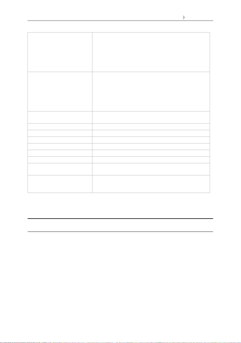
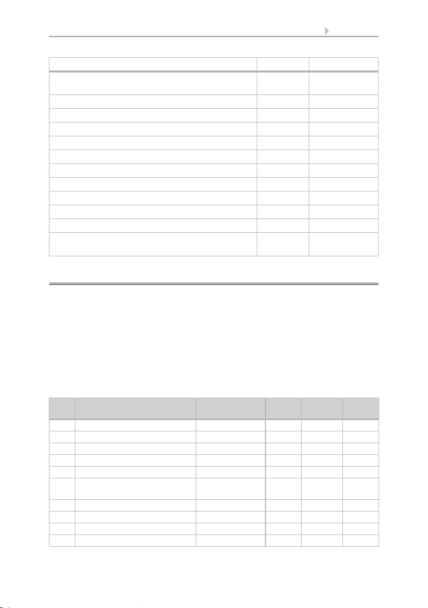
1.7.2. Overview of functions
May be set/modified via ETS on the display
Screen (brightness, screen saver...) Yes Yes
Ambient lighting Yes Yes
Logo lighting (only for engraved logos) Yes Yes
Button tone Yes Yes
Proximity sensor Yes –
Alarm Yes Yes
Display Corlo Touch KNX • Status: 09.03.2017 • Technical changes and errors reserved.
19 Description
May be set/modified via ETS on the display
Timer Yes (modification
Alarm Yes Yes
Set language Yes Yes
Enter text (editable text, names, functions) Yes Yes
Display page design (layout) Yes –
Symbols area, rockers, wheels (icons) Yes Yes
Automatic settings Yes Yes
Interface assignment Yes –
Temperature threshold values Yes –
Scenes Yes –
Logic Yes –
Access codes Yes (modification,
only)
reset only)
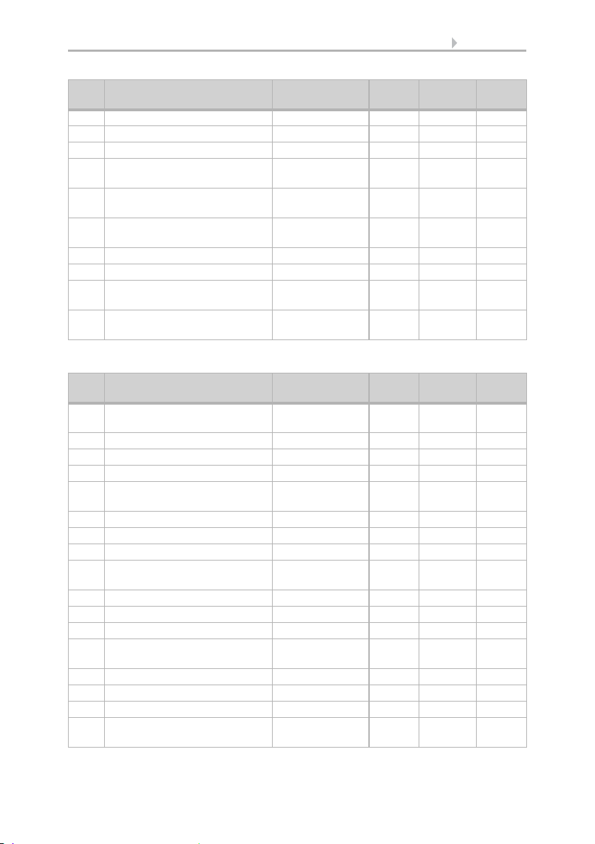
1.8. List of communications objects
DTP: Data Point Type
Abbreviation flags:
C Communication
R Read
WWrite
T Transfer
UUpdate
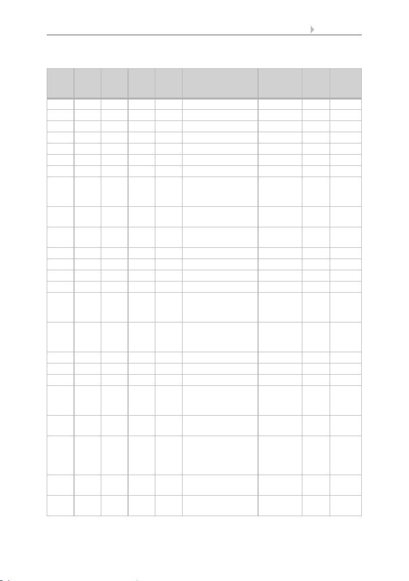
System
No. Name Function DPT Length
1 Software version Output 217.001 2 C R T
2 Unit malfunction Output 1.001 1 C R T
3 System language selection Input 234.001 2 C W
4 Key language selection Input 234.001 2 C W
5 Reset access code Input 1.017 1 C W
6 Reset to last loaded ETS
parameters
7 Date / time Input 19.001 8 C W T
8 Date Input 11.001 3 C W T
9 Time Input 10.001 3 C W T
10 Date and time request Input / Output 1.017 1 C R W
Display Corlo Touch KNX • Status: 09.03.2017 • Technical changes and errors reserved.
Input 1.017 1 C W
in byte
Flags

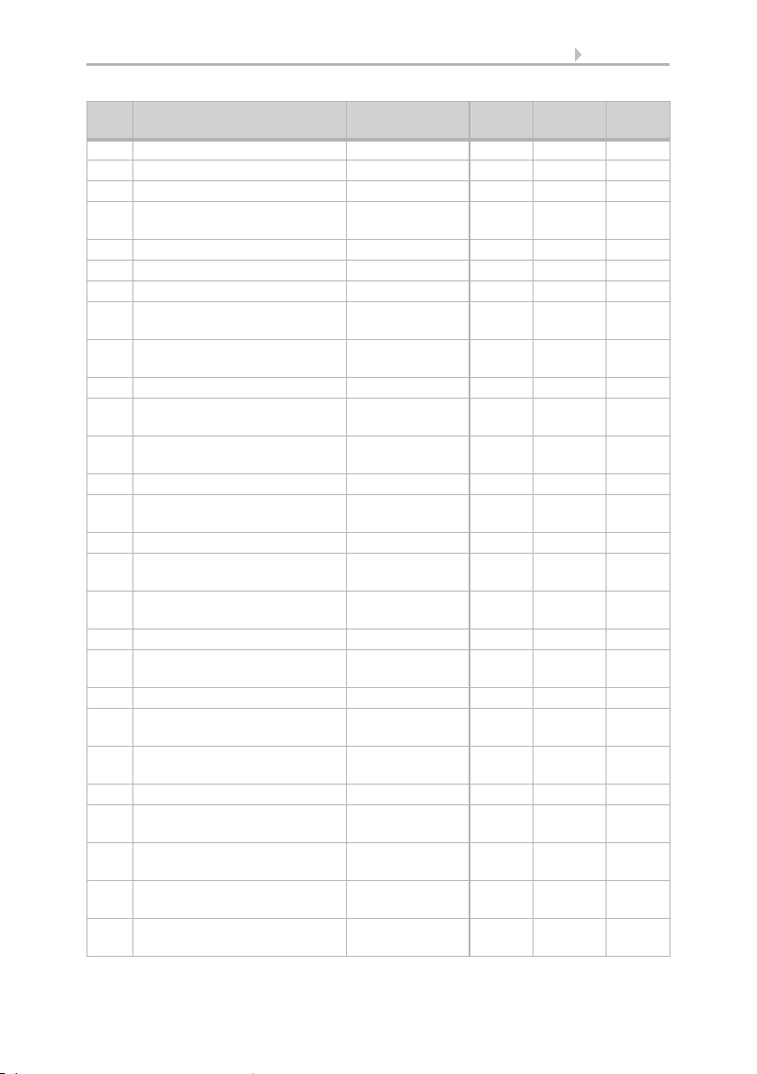
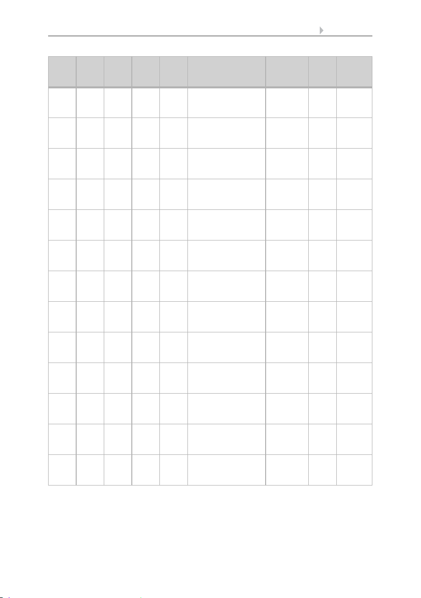
20 Description
No. Name Function DPT Length
Flags
in byte
11 Reserve
12 Status room brightness Output 1.001 1 C R T
13 Reserve
14 Display page selection Input 05. Oct. 51C W
15 Touch lock Input 1.001 1 C W
16 Temporary touch lock Input 1.001 1 C W
17 Screen saver Input 1.001 1 C W
18 Image selection from SD Card Input 5.001 1 C W
19 Reserve
20 Reserve
21 Display light brightness in % Input 5.001 1 C W
22 Ambient lighting brightness in %Input 5.001 1 C W
23 Ambient lighting red ratio in % Input / Output 5.001 1 C R W
T
24 Ambient lighting green ratio in %Input / Output 5.001 1 C R W
T
25 Ambient lighting blue ratio in %Input / Output 5.001 1 C R W
T
26 Ambient lighting RGB Input / Output 232.600 3 C R W
T
27 Reserve
28 Reserve
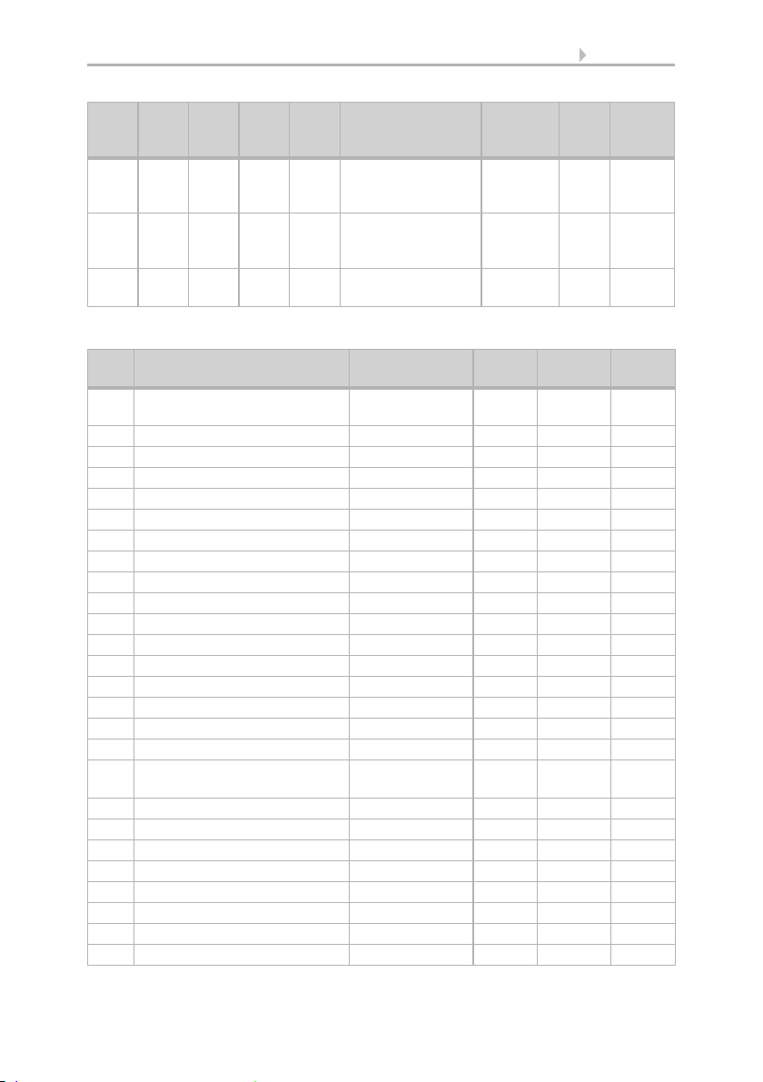
35 Reserve
36 Reserve
37 Reserve
38 Approach proximity sensor Output 5.* 1 C R T
39 Reserve
40 Retreat from proximity sensor Output 5.* 1 C R T
41-55Reserve
56 Alarm 1 Input 1.001 1 C W
57 Alarm 1 Acknowledge Input / Output 1.001 1 C W T
58 Alarm 2 Input 1.001 1 C W
59 Alarm 2 Acknowledge Input / Output 1.001 1 C W T
60 Alarm 3 Input 1.001 1 C W
61 Alarm 3 Acknowledge Input / Output 1.001 1 C W T
62 Alarm 4 Input 1.001 1 C W
63 Alarm 4 Acknowledge Input / Output 1.001 1 C W T
64 Alarm 5 Input 1.001 1 C W
Display Corlo Touch KNX • Status: 09.03.2017 • Technical changes and errors reserved.
21 Description
No. Name Function DPT Length
Flags
in byte
65 Alarm 5 Acknowledge Input / Output 1.001 1 C W T
66 Alarm 6 Input 1.001 1 C W
67 Alarm 6 Acknowledge Input / Output 1.001 1 C W T
68-79Reserve
80 Alarm activation Input / Output 1.001 1 C R W
T
81 Alarm clock time Input / Output 10.001 3 C R W
T
82 Alarm clock Output 1.001 1 C R T
83 Alarm acknowledgement Input / Output 1.001 1 C W T
84 Alarm repeat Input / Output 1.001 1 C R W
T
85-
Reserve
100
Pages
No. Name Function DTP Length
in byte
101 Page 1 area 1A Input / Output 16.000 14 C R W
102 Page 1 area 1B Output 1.010 1 C R T
103 Page 1 area 1C Input 5.001 1 C W
104 Page 1 area 1D Input 5.001 1 C W
105 Page 1 area 2A Input / Output 16.000 14 C R W
106 Page 1 area 2B Output 1.010 1 C R T
107 Page 1 area 2C Input 5.001 1 C W
108 Page 1 area 2D Input 5.001 1 C W
109 Page 1 area 3A Input / Output 16.000 14 C R W
110 Page 1 area 3B Output 1.010 1 C R T
111 Page 1 area 3C Input 5.001 1 C W
112 Page 1 area 3D Input 5.001 1 C W
113 Page 1 area 4A Input / Output 16.000 14 C R W
114 Page 1 area 4B Output 1.010 1 C R T
115 Page 1 area 4C Input 5.001 1 C W
116 Page 1 area 4D Input 5.001 1 C W
117 Page 1 area 5A Input / Output 16.000 14 C R W
Flags
T
T
T
T
T
Display Corlo Touch KNX • Status: 09.03.2017 • Technical changes and errors reserved.
22 Description
No. Name Function DTP Length
Flags
in byte
118 Page 1 area 5B Output 1.010 1 C R T
119 Page 1 area 5C Input 5.001 1 C W
120 Page 1 area 5D Input 5.001 1 C W
121 Page 1 area 6A Input / Output 16.000 14 C R W
T
122 Page 1 area 6B Output 1.010 1 C R T
123 Page 1 area 6C Input 5.001 1 C W
124 Page 1 area 6D Input 5.001 1 C W
125-
Reserve 4
132
133 Page 1 Rocker 1 Long-term Output 1.008 1 C R W
T
134 Page 1 Rocker 1 Short-term Output 1.010 1 C R T
135 Page 1 Rocker 1 Position Input 5.001 1 C R W
T
136 Page 1 Rocker 1 Slat Input 5.001 1 C R W
T
137 Page 1 Rocker 1 Feedback Input 1.001 1 C W
138 Page 1 Rocker 2 Long-term Output 1.008 1 C R W
T
139 Page 1 Rocker 2 Short-term Output 1.010 1 C R T
140 Page 1 Rocker 2 Position Input 5.001 1 C R W
T
141 Page 1 Rocker 2 Slat Input 5.001 1 C R W
T
142 Page 1 Rocker 2 Feedback Input 1.001 1 C W
143 Page 1 Rocker 3 Long-term Output 1.008 1 C R W
T
144 Page 1 Rocker 3 Short-term Output 1.010 1 C R T
145 Page 1 Rocker 3 Position Input 5.001 1 C R W
T
146 Page 1 Rocker 3 Slat Input 5.001 1 C R W
T
147 Page 1 Rocker 3 Feedback Input 1.001 1 C W
148 Page 1 rotary control value [R] Output 14.* 4 C R W
T
149 Page 1 rotary control value [G] Output 5.001 1 C R W
T
150 Page 1 rotary control value [B] Output 5.001 1 C R W
T
151-
Page 2
200
Display Corlo Touch KNX • Status: 09.03.2017 • Technical changes and errors reserved.

23 Description
No. Name Function DTP Length
in byte
201-
Page 3
250
251-
Page 4
300
301-
Page 5
350
351-
Page 6
400
401-
Page 7
450
451-
Page 8
500
501-
Page 9
550
551-
Page 10
600
Automatic
No. Name Function DPT Length
601 Automatic inside temp. meas.
Input 9.001 2 C W
value
602 Automatic inside humidity
Input 9.007 2 C W
meas. value
603 Automatic CO2 meas. value in
Input 9.008 2 C W
ppm
604 Automatic wind measuring
Input 9.005 2 C W
value
605 Automatic rain Input 1.002 1 C W
606 Automatic outdoor
Input 9.001 2 C W
temperature measuring value
607 Automatic brightness
Input 9.004 2 C W
measuring value
608 Automatic cooling status Input 1.001 1 C W
609 Reserve
610 Reserve
in byte
Flags
Flags
Display Corlo Touch KNX • Status: 09.03.2017 • Technical changes and errors reserved.
24 Description
Objects automatic channels for shading, windows, ventilation or light
No.
No.
No.
No.
No.
Auto
1
Auto
2
Auto
3
Auto
4
Name Function DPT Flags
Auto
5
611 646 681 716 751 Reserve
612 647 682 717 752 Reserve
613 648 683 718 753 Automatic X Reset Input 1.001 C W
614 649 684 719 754 Reserve
615 650 685 720 755 Automatic X Block Input 1.001 C W
616 651 686 721 756 Reserve
617 652 687 722 757 Automatic X Safety Output 1.001 C R T
618 653 688 723 758 Automatic X
Output 1.001 C R T
Precipitation
warning
619 654 689 724 759 Automatic X Wind
Output 1.001 C R T
warning
620 655 690 725 760 Automatic X Frost
Output 1.001 C R T
warning
621 656 691 726 761 Reserve
622 657 692 727 762 Reserve
623 658 693 728 763 Reserve
624 659 694 729 764 Reserve
625 660 695 730 765 Automatic X Status
Output 1.001 C R T
indoor temperature
block
626 661 696 731 766 Automatic X Status
Output 1.001 C R T
outdoor
temperature block
627 662 697 732 767 Reserve
628 663 698 733 768 Reserve
629 664 699 734 769 Reserve
630 665 700 735 770 Automatic X
Output 5.001 C R T
movement position
- brightness
631 666 701 736 771 Automatic X slat
Output 5.001 C R T
position
632 667 702 737 772 Automatic X
Input 5.001 C W
movement position
- brightness
feedback
633 668 703 738 773 Automatic X slat
Input 5.001 C W
position feedback
634-
669-
704-
739-
774-
645
680
715
750
Reserve
785
Display Corlo Touch KNX • Status: 09.03.2017 • Technical changes and errors reserved.

25 Description
Objects automatic channels for temperature control
No.
No.
No.
No.
No.
Auto
1
Auto
2
Auto
3
Auto
4
Name FunctionDPT Flags
Auto
5
611 646 681 716 751 Temp. controller:
Ec o- St an dby
HVAC 1
612 647 682 717 752 Temp. controller:
Comfort activation
HVAC 2
613 648 683 718 753 Reserve
614 649 684 719 754 Temp. controller:
Frost/heat
activation
615 650 685 720 755 Temp. controller:
Blocking object
616 651 686 721 756 Temp. controller:
Current set point
617 652 687 722 757 Temp. controller:
Switching object
(0:Heating |
1:Cooling)
618 653 688 723 758 Temp. controller:
Set point, comfort
heating
619 654 689 724 759 Temp. controller:
Set point, night-
time heating (1:+ |
0:-)
620 655 690 725 760 Temp. controller:
Reference value,
comfort cooling
621 656 691 726 761 Temp. controller:
Reference value,
comfort cooling
(1:+ | 0:-)
622 657 692 727 762 Temp. controller:
Reference value,
standby heating
623 658 693 728 763 Temp. controller:
Set point, standby
heating (1:+ | 0:-)
624 659 694 729 764 Temp. controller:
Set point, Standby
cooling
Input 1.003 C W
Input 1.003 C W
Input 1.003 C R W
T
Input 1.003 C R W
T
Output 9.001 C R T
Input 1.002 C W
Input /
Output
9.001 C R W
T
Input 1.002 C W
Input /
Output
9.001 C R W
T
Input 1.002 C W
Input /
Output
9.001 C R W
T
Input 1.002 C W
Input /
Output
9.001 C R W
T
Display Corlo Touch KNX • Status: 09.03.2017 • Technical changes and errors reserved.
26 Description
No.
No.
No.
No.
No.
Auto
1
Auto
2
Auto
3
Auto
4
Name FunctionDPT Flags
Auto
5
625 660 695 730 765 Temp. controller:
Set point, standby
cooling(1:+ | 0:-)
626 661 696 731 766 Temp. controller:
Set point, eco
heating
627 662 697 732 767 Temp. controller:
Set point, eco
heating (1:+ | 0:-)
628 663 698 733 768 Temp. controller:
Set point, Eco
cooling
629 664 699 734 769 Temp. controller:
Set point, eco
cooling (1:+ | 0:-)
630 665 700 735 770 Temp. controller:
Control variable,
heating (level 1)
631 666 701 736 771 Temp. controller:
Control variable,
Heating (level 2)
632 667 702 737 772 Temp. controller:
Control variable,
cooling level 1
633 668 703 738 773 Temp. controller:
Control variable,
Cooling (level 2)
634 669 704 739 774 Temp. controller:
Status – Heating 1
(1=ON | 0=OFF)
635 670 705 740 775 Temp. controller:
Status – Heating 2
(1=ON | 0=OFF)
636 671 706 741 776 Temp. controller:
Status – Cooling 1
(1=ON | 0=OFF)
637 672 707 742 777 Temp. controller:
Status – Cooling 2
(1=ON | 0=OFF)
Input 1.002 C W
Input /
Output
9.001 C R W
T
Input 1.002 C W
Input /
Output
9.001 C R W
T
Input 1.002 C W
Output 5.001 C R T
Output 5.001 C R T
Output 5.001 C R T
Output 5.001 C R T
Output 1.002 C R T
Output 1.002 C R T
Output 1.002 C R T
Output 1.002 C R T
Display Corlo Touch KNX • Status: 09.03.2017 • Technical changes and errors reserved.
27 Description
No.
No.
No.
No.
No.
Auto
1
Auto
2
Auto
3
Auto
4
Name FunctionDPT Flags
Auto
5
638 673 708 743 778 Temp. controller:
Comfort extension
time (in sec)
639 674 709 744 779 Temp. controller:
Comfort delay
status
640-
675-
710-
745-
780-
645
680
715
750
Reserve
785
Miscellaneous
Input /
Output
Input /
Output
7.005 C R W
T
1.002 C R W
T
No. Name Function DPT Length
Flags
in byte
786-
Reserve
790
791 Period 1 Switching output Output 14.* 4 C R T
792 Period 2 Switching output Output 14.* 4 C R T
793 Period 3 Switching output Output 14.* 4 C R T
794 Period 4 Switching output Output 14.* 4 C R T
795 Period 5 Switching output Output 14.* 4 C R T
796 Period 6 Switching output Output 14.* 4 C R T
797 Period 7 Switching output Output 14.* 4 C R T
798 Period 8 Switching output Output 14.* 4 C R T
799 Period 9 Switching output Output 14.* 4 C R T
800 Period 10 Switching output Output 14.* 4 C R T
801 Period 11 Switching output Output 14.* 4 C R T
802 Period 12 Switching output Output 14.* 4 C R T
803 Period 13 Switching output Output 14.* 4 C R T
804 Period 14 Switching output Output 14.* 4 C R T
805 Period 15 Switching output Output 14.* 4 C R T
806 Period 16 Switching output Output 14.* 4 C R T
807-
Reserve
819
820 Load / save scene Input 18.001 1 C W
821 Scene object 1 Input / Output 9.* 4 C R T
822 Scene object 2 Input / Output 9.* 4 C R T
823 Scene object 3 Input / Output 9.* 4 C R T
824 Scene object 4 Input / Output 9.* 4 C R T
825 Scene object 5 Input / Output 9.* 4 C R T
826 Scene object 6 Input / Output 9.* 4 C R T
827 Scene object 7 Input / Output 9.* 4 C R T
Display Corlo Touch KNX • Status: 09.03.2017 • Technical changes and errors reserved.

28 Description
No. Name Function DPT Length
Flags
in byte
828 Scene object 8 Input / Output 9.* 4 C R T
829 Scene object 9 Input / Output 9.* 4 C R T
830 Scene object 10 Input / Output 9.* 4 C R T
831 Scene object 11 Input / Output 9.* 4 C R T
832 Scene object 12 Input / Output 9.* 4 C R T
833 Scene object 13 Input / Output 9.* 4 C R T
834 Scene object 14 Input / Output 9.* 4 C R T
835 Scene object 15 Input / Output 9.* 4 C R T
836 Scene object 16 Input / Output 9.* 4 C R T
837-
Reserve
850
851 Button 1 Extended Output 1.008 1 C R T
852 Button 1 Brief Output 1.010 1 C R T
853 Switch button 1 on / off Input / Output 1.001 1 C R W
T
854 Button 1 Relative dimming Input / Output 3.007 1 C R W
T
855 Button 1 - 8-bit encoder Output 5* 1 C R T
856 Button 1 - 16-bit encoder Output 9* 2 C R T
857 Button 1 Scene Output 18.001 1 C R T
858 Button 2 Extended Output 1.008 1 C R T
859 Button 2 Brief Output 1.010 1 C R T
860 Switch button 2 on / off Input / Output 1.001 1 C R W
T
861 Button 2 Relative dimming Input / Output 3.007 1 C R W
T
862 Button 2 - 8-bit encoder Output 5* 1 C R T
863 Button 2 - 16-bit encoder Output 9* 2 C R T
864 Button 2 Scene Output 18.001 1 C R T
865 Button 3 Extended Output 1.008 1 C R T
866 Button 3 Brief Output 1.010 1 C R T
867 Switch button 3 on / off Input / Output 1.001 1 C R W
T
868 Button 3 Relative dimming Input / Output 3.007 1 C R W
T
869 Button 3 - 8-bit encoder Output 5* 1 C R T
870 Button 3 - 16-bit encoder Output 9* 2 C R T
871 Button 3 Scene Output 18.001 1 C R T
872 Button 4 Extended Output 1.008 1 C R T
873 Button 4 Brief Output 1.010 1 C R T
Display Corlo Touch KNX • Status: 09.03.2017 • Technical changes and errors reserved.
 Loading...