

Elsner Cala KNX AQS/TH, Cala KNX T, Cala KNX TH Installation And Adjustment

Item numbers
Cala KNX AQS/TH: 70603 (black), 70608 (white)
Cala KNX TH: 70602 (black), 70607 (white)
Cala KNX T: 70601 (black), 70606 (white)
EN
Cala KNX
Indoor climate sensors with touch display
Illustration with frame (not included in the deliverables)
Installation and Adjustment


1 Contents
Elsner Elektronik GmbH • Sohlengrund 16 • 75395 Ostelsheim • Germany
Sensor with Cala KNX display • from ETS programme version 1.0 •
Version: 13.03.2017. Technical changes and errors excepted.
1. Description ........................................................................................... 5
1.0.1. Deliverables ................................................................................................... 6
1.1. Technical specifications ........................................................................................... 7
1.1.1. Measuring accuracy ...................................................................................... 8
2. Installation and commissioning ........................................................... 8
2.1. Installation notes ...................................................................................................... 8
2.2. Installation location .................................................................................................. 9
2.3. Device design ........................................................................................................... 9
2.4. Sensor assembly .................................................................................................... 10
2.5. Notes on mounting and commissioning .............................................................. 11
3. Addressing the equipment ................................................................. 11
4. Maintenance and care ........................................................................ 11
5. Operating the device via the touch display ....................................... 13
5.1. Menu overview ....................................................................................................... 14
5.2. Device settings ....................................................................................................... 15
5.2.1. Display settings ........................................................................................... 15
5.2.2. Button tone .................................................................................................. 19
5.2.3. Version ......................................................................................................... 20
5.3. Sensor system (measured value display) ............................................................ 20
5.4. Temperature control .............................................................................................. 22
5.5. Light ......................................................................................................................... 23
5.6. Drive (shading, window) ........................................................................................ 25
6. Transfer protocol ............................................................................... 27
6.1. List of all communications objects ....................................................................... 27
7. Setting the parameters and functions for all models ........................ 45
7.1. Behaviour on power failure/ restoration of power .............................................. 45
7.2. General settings ..................................................................................................... 45
7.3. Display ..................................................................................................................... 45
7.4. Button tone ............................................................................................................. 47
7.5. Menus ...................................................................................................................... 47
7.5.1. Settings ........................................................................................................ 48
7.5.2. Sensor system ............................................................................................. 48
7.5.3. Temperature control ................................................................................... 48
7.5.4. Light 1-3 ....................................................................................................... 49
7.5.5. Drive 1-3 ...................................................................................................... 50
7.6. Variable comparator .............................................................................................. 50
7.6.1. Control variable comparator 1/2/3/4 .......................................................... 50
7.7. Computer ................................................................................................................ 51
7.7.1. Computers 1-8 ............................................................................................. 51
7.8. Logic ........................................................................................................................ 55
7.8.1. AND logic 1-8 and OR logic outputs 1-8 ................................................... 55
7.8.2. Connection inputs of the AND logic .......................................................... 57
7.8.3. Connection inputs of the OR logic ............................................................. 60
7.9. Button interfaces .................................................................................................... 60

2 Contents
Elsner Elektronik GmbH • Sohlengrund 16 • 75395 Ostelsheim • Germany
Sensor with Cala KNX display • from ETS programme version 1.0 •
Version: 13.03.2017. Technical changes and errors excepted.
7.9.1. Interface 1-4 ................................................................................................. 60
7.9.2. Control modes for drive control ................................................................ 63
8. Temperature parameter settings ....................................................... 66
8.1. Temperature Measurement ................................................................................... 66
8.2. Temperature threshold values .............................................................................. 66
8.2.1. Threshold value 1, 2, 3, 4 ........................................................................... 66
8.3. Temperature PI control .......................................................................................... 69
8.3.1. Heating control level 1/2 ............................................................................. 74
8.3.2. Cooling control level 1/2 ............................................................................. 76
8.4. Summer Compensation ......................................................................................... 78
9. Humidity parameter settings ............................................................. 80
9.1. Humidity Measurement ......................................................................................... 80
9.2. Humidity threshold values .................................................................................... 80
9.2.1. Threshold value 1, 2, 3, 4 ........................................................................... 81
9.3. Humidity PI control ................................................................................................ 83
9.4. Dewpoint measurement ........................................................................................ 86
9.4.1. Cooling medium temp. monitoring ........................................................... 86
9.5. Absolute humidity .................................................................................................. 88
9.6. Comfort field ........................................................................................................... 89
10. CO2 parameter settings ..................................................................... 90
10.1.CO2 Measurement ................................................................................................. 90
10.2.CO2 threshold values ............................................................................................ 90
10.2.1.Threshold value 1, 2, 3, 4 ........................................................................... 91
10.3.CO2 PI-control ........................................................................................................ 93

3 Clarification of signs
This manual is amended periodically and will be brought into line with new software
releases. The change status (software version and date) can be found in the contents footer.
If you have a device with a later software version, please check
www.elsner-elektronik.de in the menu area "Service" to find out whether a more up-todate version of the manual is available.
Clarification of signs used in this manual
Installation, inspection, commissioning and troubleshooting of the device
must only be carried out by a competent electrician.
Safety advice.
Safety advice for working on electrical connections, components,
etc.
DANGER!
... indicates an immediately hazardous situation which will lead to
death or severe injuries if it is not avoided.
WARNING!
... indicates a potentially hazardous situation which may lead to
death or severe injuries if it is not avoided.
CAUTION!
... indicates a potentially hazardous situation which may lead to
trivial or minor injuries if it is not avoided.
ATTENTION!
... indicates a situation which may lead to damage to property if it is
not avoided.
ETS In the ETS tables, the parameter default settings are marked by
underlining.

4 Clarification of signs

5 Description
Sensor with Cala KNX display • Version: 13.03.2017 • Technical changes and errors excepted.
This document describes the functions for ALL device models.
Please check the information at the beginning of the chapter and in the
text which describes the functions available for the respective individual
models.
1. Description
The Sensor with Cala KNX display for the KNX bus system measures various ambient climate. Via the bus, the indoor sensor can receive external values and process
them further with its own data to a total value (mixed value, e.g. room average).
All measured values can be used for the control of threshold value-dependent switching outputs. States can be linked via AND logic gates and OR logic gates. Multi-functional modules change input data as required by means of calculations, querying a
condition, or converting the data point type. In addition, an integrated manipulated
variable comparator can compare and output variables that were received via communication objects.
Integrated PI-controllers control ventilation (according to humidity or CO
2
-concentration) and/or heating/cooling (according to temperature), depending on the respective
model.
Cala KNX features a touch display that shows various display and control pages depending on the individual configuration. There is one page available that shows the
current measured values, a menu area to adjust device settings and pages with touch
control elements for internal temperature control, for light (manual switching or dimming), for shades or windows (manual operation).
Cala KNX is supplemented with a frame of the switch series used in buildings, and
thus fits seamlessly into the interior fittings.
Common features in all models:
• Colour touch display with display pages for device settings, measuring
values, controls of 1x heating/cooling, 3x light, 3x drive (shading, window)
• Screen saver (clock, off) and key tone may be switched on or off.
• 4 inputs for binary contacts or T-NTC temperature sensor.
• 8 AND and 8 OR logic gates each with 4 inputs. All switching events as well
as 16 logic inputs (in the form of communications objects) can be used as
inputs for the logic gates. The output from each gate can be configured
optionally as 1-bit or 2 x 8-bit
• 8 multi-function modules (computers) for changing the input data by
calculations, by querying a condition or by converting the data point type
• 4 manipulated variable comparators to output minimum, maximum or
average values. 5 inputs each for values received via communication objects
Cala KNX AQS/TH functions (no. 70603, 70608):
• Measuring the CO
2
-concentration of the air, the temperature and air
humidity (relative, absolute), each with mixed value calculation. The share
of internal measurement value and external value can be set as a percentage

6 Description
Sensor with Cala KNX display • Version: 13.03.2017 • Technical changes and errors excepted.
• Bus message, whether the values for temperature and air humidity are within
the comfort field (DIN 1946). Dew point calculation
• Threshold values can be adjusted per parameter or via communication
objects
• PI-controller for heating (one or two-level) and cooling (one or two-level)
according to temperature. Regulation according to separate set points or basic
set point temperature
• PI controller for ventilation according to humidity and CO
2
-concentration:
Ventilate/Air (one-level) or Ventilate (one or two-levels)
• Summer compensation for cooling systems. A characteristic curve matches
the target temperature in the room to the external temperature and sets the
minimum and maximum target temperature values
Cala KNX TH functions (no. 70602, 70607):
• Temperature and air humidity measurement (relative, absolute), in each
case with mixed value calculation. The share of internal measurement value
and external value can be set as a percentage
• Bus message, whether the values for temperature and air humidity are within
the comfort field (DIN 1946). Dew point calculation
• Threshold values can be adjusted per parameter or via communication
objects
• PI-controller for heating (one or two-level) and cooling (one or two-level)
according to temperature. Regulation according to separate setpoints or basic
set point temperature
• PI controller for ventilation according to humidity: Ventilate/Air (one-level)
or Ventilate (one or two-level)
• Summer compensation for cooling systems. A characteristic curve matches
the target temperature in the room to the external temperature and sets the
minimum and maximum target temperature values
Cala KNX T functions (no. 70601, 70606):
• Measuring the Temperature with a mixed value calculation. The share of
internal measurement value and external value can be set as a percentage
• Threshold values can be adjusted per parameter or via communication
objects
• PI-controller for heating (one or two-level) and cooling (one or two-level)
according to temperature. Regulation according to separate set points or basic
set point temperature
• Summer compensation for cooling systems. A characteristic curve matches
the target temperature in the room to the external temperature and sets the
minimum and maximum target temperature values
Configuration is made using the KNX software ETS. The product file can be downloaded from the Elsner Elektronik website on www.elsner-elektronik.de in the “Service” menu.
1.0.1. Deliverables
• Housing with display
7 Description
Sensor with Cala KNX display • Version: 13.03.2017 • Technical changes and errors excepted.
• Base plate
• Analogue/digital supply line
Additionally required (not included in the deliverables):
• Junction box Ø 60 mm, 42 mm deep
• Frame (for insert 55 x 55 mm), compatible to the switch scheme used in the
building
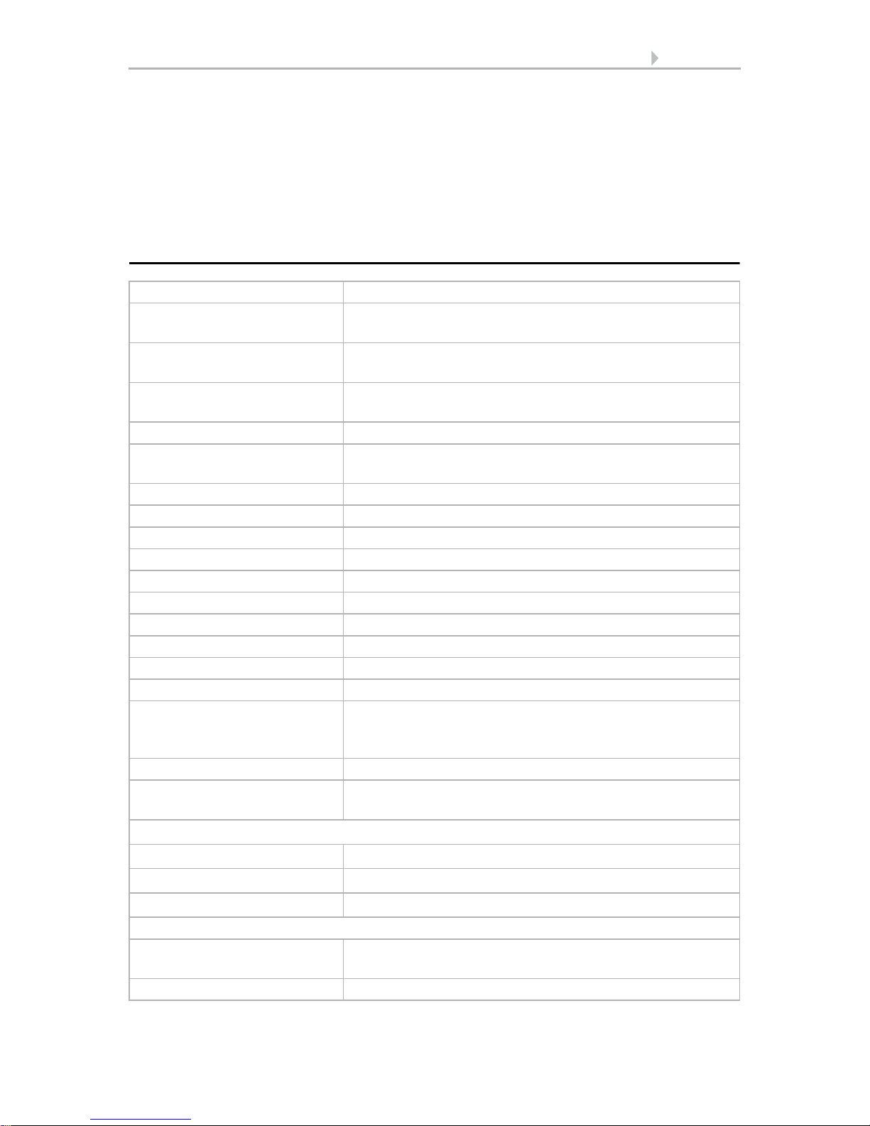
1.1. Technical specifications
Material Real glass, plastic
Display Visible diagonal: 2.3 inch (59 mm)
Resolution: 320 × 240 pixel
Colours black glass, black housing
white glass, white housing
Assembly Flush mounting
(Wall mounting in junction box Ø 60 mm, 42 mm deep)
Protection category IP 20
Dimensions approx. 55 × 55 × 35 (W × H × D, mm), mounting depth
approx. 7 mm
Total weight approx. 90 gr (incl. supply line, base plate
Ambient temperature Operation -20…+70°C, storage -30…+70°C
Ambient humidity max. 95% RH, avoid condensation
Operating voltage KNX bus voltage
Bus current max. 18 mA
Data output KNX +/- bus connector terminal
BCU type Integrated microcontroller
PEI type 0
Group addresses max. 2000
Assignments max. 2000
Communication objects Cala KNX AQS/TH: 405
Cala KNX TH: 367
Cala KNX T: 313
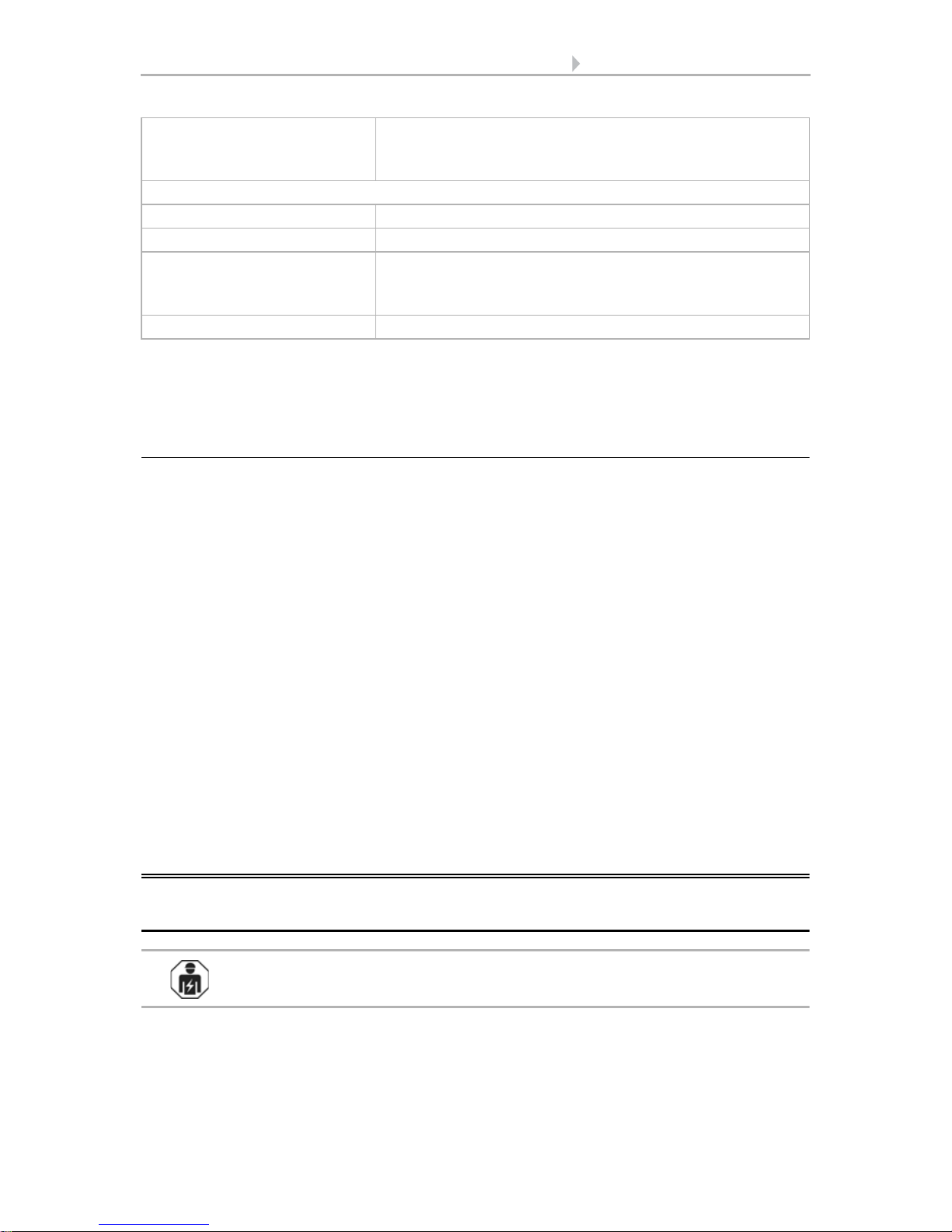
Inputs 4× analogue/ digital, max. cable length 10 m.
measuring range T-NTC tem-
perature sensor on Cala input
-40°C...+80°C
CO
2
-sensor (for Cala KNX AQS/TH):
CO2-measuring range 0...2000 ppm
CO2 resolution 1 ppm
CO2 accuracy ± 50 ppm ± 3% of the measured value
Temperature sensor (for Cala KNX AQS/TH, Cala KNX TH, Cala KNX T):
Temperature measuring
range
-20…+70°C
Temperature resolution 0.1°C
8 Installation and commissioning
Sensor with Cala KNX display • Version: 13.03.2017 • Technical changes and errors excepted.
* Please note the information on Measuring accuracy, page 8
The product is compliant with the provisions of EC guidelines.
1.1.1. Measuring accuracy
Measurement deviations due to sources of interference (see chapter Installation location) must be corrected in the ETS in order to ensure the specified accuracy of the sen-
sor (offset). For a correct CO
2
measurement it is necessary to install the device in a
windproof socket.
The specified CO
2
measurement accuracy is achieved after a run-in of 24 hours
(without bus voltage interruption), if the sensor comes into contact with fresh air
(350…450 ppm) at least once during this period. During the warm-up phase the reading
may not be displayed at all or wrongly, or remain frozen at 2001.
After this, the CO
2
-sensor performs a self-calibration every two weeks, in which the
lowest CO
2
-value measured during this period (without bus voltage interruption) is taken as a reference for fresh air.
In order to ensure permanent accuracy, the sensor should be supplied with fresh air at
least once every two weeks. This is normally the case during room ventilation.
During Temperature measurement, the self-heating of the device is taken into consideration by the electronics. It is compensated for by the software, therefore the displayed/output inside temperature measuring value is correct.
2. Installation and commissioning
2.1. Installation notes
Installation, testing, operational start-up and troubleshooting should
only be performed by an electrician.
Temperature accuracy* ± 0.8°C at -25…-10°C
± 0.5°C at -10…+65°C
± 0.6°C at +65…+70°C
Humidity sensor (for Cala KNX AQS/TH, Cala KNX TH):
Humidity measuring range 0% HR … 100% HR
Humidity resolution 0.1%
Humidity accuracy ±7,5% HR at 0...10% HR
±4,5% HR at 10...90% HR
±7,5% HR at 90...100% HR
Humidity drift ± 0.5% RH per year in normal atmosphere
9 Installation and commissioning
Sensor with Cala KNX display • Version: 13.03.2017 • Technical changes and errors excepted.
CAUTION!
Live voltage!
There are unprotected live components inside the device.
• National legal regulations are to be followed.
• Ensure that all lines to be assembled are free of voltage and take
precautions against accidental switching on.
• Do not use the device if it is damaged.
• Take the device or system out of service and secure it against
unintentional use, if it can be assumed, that risk-free operation is no
longer guaranteed.
The device is only to be used for its intended purpose. Any improper modification or
failure to follow the operating instructions voids any and all warranty and guarantee
claims.
After unpacking the device, check it immediately for possible mechanical damage. If it
has been damaged in transport, inform the supplier immediately.
The device may only be used as a fixed-site installation; that means only when assembled and after conclusion of all installation and operational start-up tasks and only in
the surroundings designated for it.
Elsner Elektronik is not liable for any changes in norms and standards which may occur
after publication of these operating instructions.
2.2. Installation location
The sensor is installed in a flush-mounted box (Ø 60 mm, 42 mm deep).
The sensor may only be installed and used in dry interior spaces.
Avoid condensation.
When selecting an installation location, please ensure that the measurement results
are affected as little as possible by external influences. Possible sources of interference
include:
• Direct sunlight
• Draughts from windows and doors
• Draughts from ducts which lead to the junction box in which the sensor is
mounted from other rooms.
• Warming or cooling of the building structure on which the sensor is mounted,
e.g. due to sunlight, heating or cold water pipes
• Connection lines, which lead from warmer or colder areas to the sensor
Temperature variations from such sources of interference must be corrected in the ETS
in order to ensure the specified accuracy of the sensor (temperature offset).
2.3. Device design
View with frame and base plate.

10 Installation and commissioning
Sensor with Cala KNX display • Version: 13.03.2017 • Technical changes and errors excepted.
2.4. Sensor assembly
First, place the wind-proof box with the supply connection. Seal the inlet tubes as well,
in order to prevent drafts.
Then screw the base plate onto the socket and position the frame of the switch range
on top of this. Connect the bus lines +/- to the black-red KNX plug and plug the KNX
plug into the intended slot (no. 8). If required, connect the analogue/digital inputs via
the breakout cable that is included in the delivery.
3
5
7
8
6
1
Fig. 1a Fig. 1b
2
1 Frame (not included in the
deliverables)
2 Base plate
3 Openings for air circulation
4 Slot supply line inputs
5 Programming button (recessed) for
teaching the device
6 Programming LED (recessed)
7 Catches
8KNX terminal BUS +/-
4
Fig. 2
Analogue/digital supply line inputs:
Input 1: white / black (GND)
Input 2: yellow / black (GND)
Input 3: purple / black (GND)
Input 4: blue / black (GND)

11 Addressing the equipment
Sensor with Cala KNX display • Version: 13.03.2017 • Technical changes and errors excepted.
Insert the housing firmly onto the metal frame using the catches so that sensor and
frame are fixed together.
2.5. Notes on mounting and commissioning
Never expose the device to water (e.g. rain) or dust. This can damage the electronics.
You must not exceed a relative humidity of 95%. Avoid condensation.
After the bus voltage has been applied, the device will enter an initialisation phase lasting a few seconds. During this phase no information can be received or sent via the
bus.After the bus voltage has been applied, the device will enter an initialisation phase
lasting a few seconds. During this phase no information can be received or sent via the
bus.
3. Addressing the equipment
The equipment is delivered with the bus address 15.15.255. You can program a different address in the ETS by overwriting the address 15.15.255 or by teaching the device
via the programming button.
The programming button can be reached through the opening on the rear of the housing; it is recessed. Use a thin object to reach the button, e.g. a 1.5 mm² wire.
4. Maintenance and care
Fingerprints on the display and the housing are best removed with a cloth moistened
with water or a microfibre cloth. Do not use an abrasive cleaning agent or aggressive
cleansing agents.

12 Maintenance and care
Sensor with Cala KNX display • Version: 13.03.2017 • Technical changes and errors excepted.

13 Operating the device via the touch display
Sensor with Cala KNX display • Version: 13.03.2017 • Technical changes and errors excepted.
5. Operating the device via the touch
display
The available display and operating options on the device depend on the ETS "menu"
settings. Here you decide which menus are shown.
You call up the different menus on the display by swiping to the right or left. You navigate to sub-menus via the touch keys and the navigation bar at the bottom of the
screen using the symbols Back (= cancel), start page, OK (= confirm).
Other display settings can be adjusted in the ETS in the "Display" and "Button tone"
sections. However, you may also use the "Settings" menu on the display itself if it is
released for display.
14 Operating the device via the touch display
Sensor with Cala KNX display • Version: 13.03.2017 • Technical changes and errors excepted.
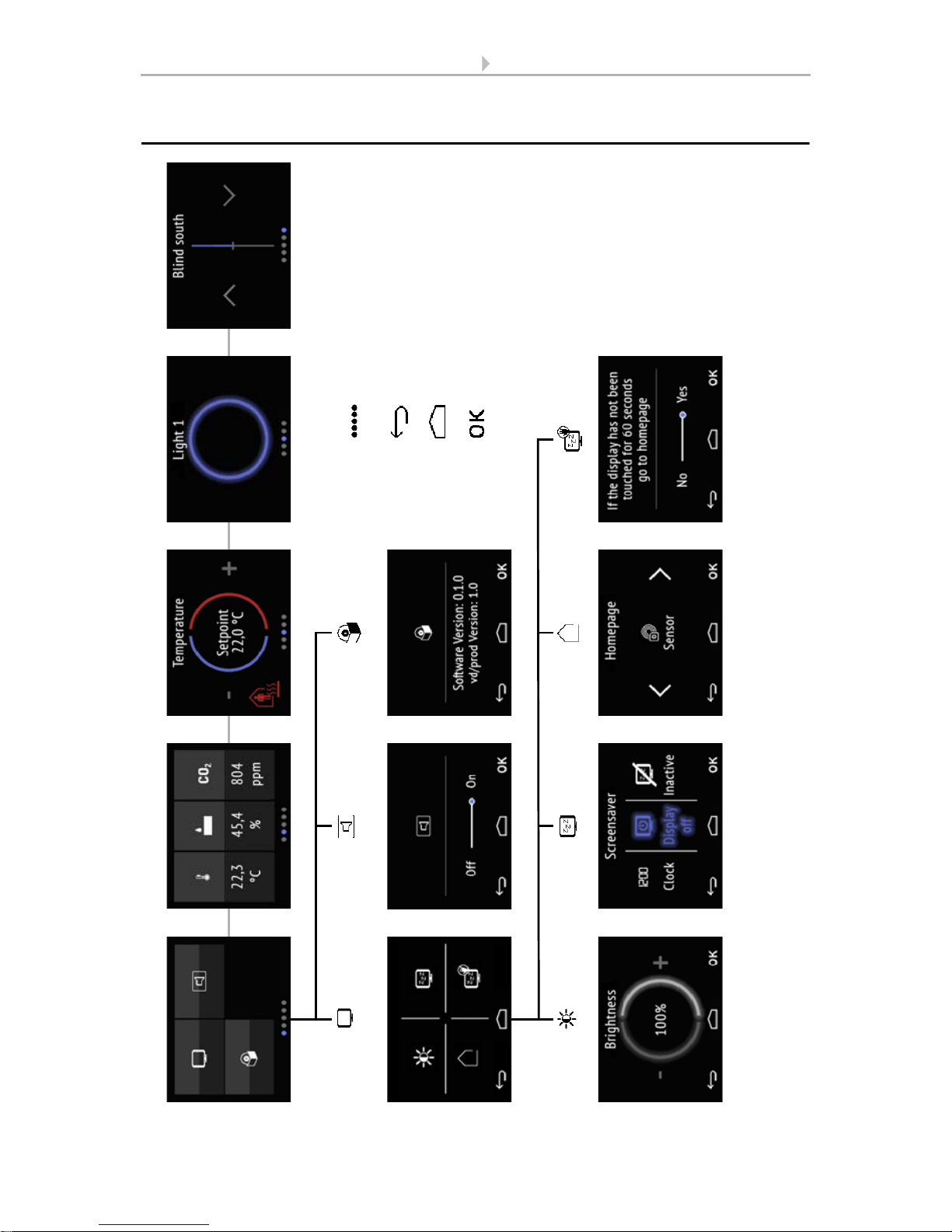
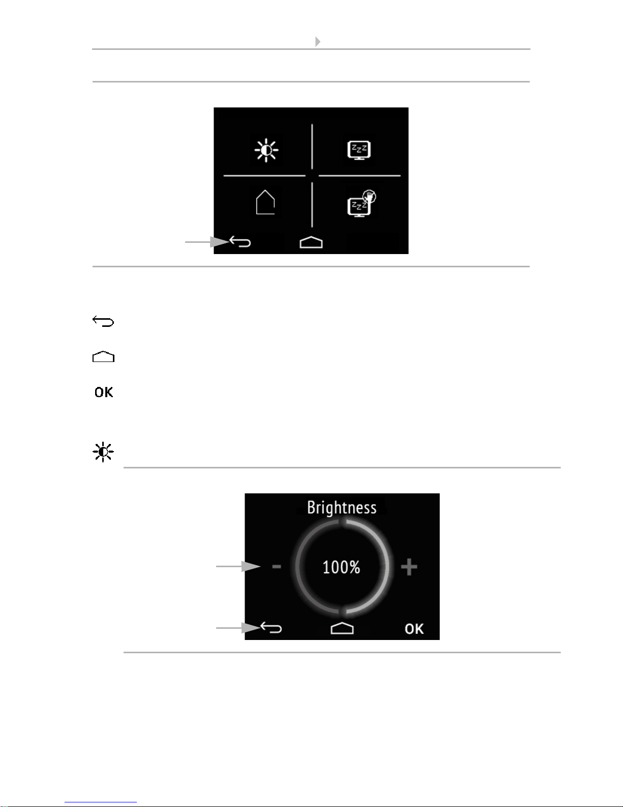
5.1. Menu overview
Device settings Sensor system* Light 1-3 operation* Drive 1-3 operation*
* Setting depends on the device model or the settings selected.
Temperature settings*
Fig. 3
Navigation by swiping, top
menu level.
Cancel key. Go up one menu
level without saving.
Start page key. To start page
without saving.
Confirm key. Save and go up
one menu level.
Display Button tone Version information

15 Operating the device via the touch display
Sensor with Cala KNX display • Version: 13.03.2017 • Technical changes and errors excepted.
5.2. Device settings
The adaptation of display settings on the device is only possible if the "Settings" have
been activated in the ETS setting item "Menus".
Menus, page 47
You can modify screen settings on the
• "Settings" display pages
• switch the button tone on or off
• show the device and application version
(1) The dots on the lower display edge symbolise the individual menu pages in the
main menus. The currently selected position is marked in colour. Swipe to the left or
right on the display to show the other menu pages.
5.2.1. Display settings
Tap on the screen symbol to call up the screen settings.
Here you can adjust
• the display brightness
• select the type of screen saver
• determine the start page
• decide if you want the display to switch to the start page if it has not been
touched for a certain period of time.
Fig. 4: "Settings" menu
Display
Version
Button tone
1
16 Operating the device via the touch display
Sensor with Cala KNX display • Version: 13.03.2017 • Technical changes and errors excepted.
(1) The touch keys on the navigation bar in the overview and in all sub-menus allow
you to
cancel and return to the previous menu level without saving
jump to the start page without saving
and also to confirm and return to the previous menu level after saving from the
settings screens
Display brightness
Tap on the brightness symbol to call up the display brightness settings.
(1) Tap on the left part of the screen (-) to reduce screen brightness. Tap on the right
part (+) to increase brightness. Settings range 1...100%.
(2) The navigation bar keys take you back to the start page or let you confirm the
changes with OK.
Fig. 5: Menu Settings > Display
Brightness
Start display
Screen saver
Switch
1
to start page
Fig. 6: Menu Settings > Display > Brightness
2
1
17 Operating the device via the touch display
Sensor with Cala KNX display • Version: 13.03.2017 • Technical changes and errors excepted.
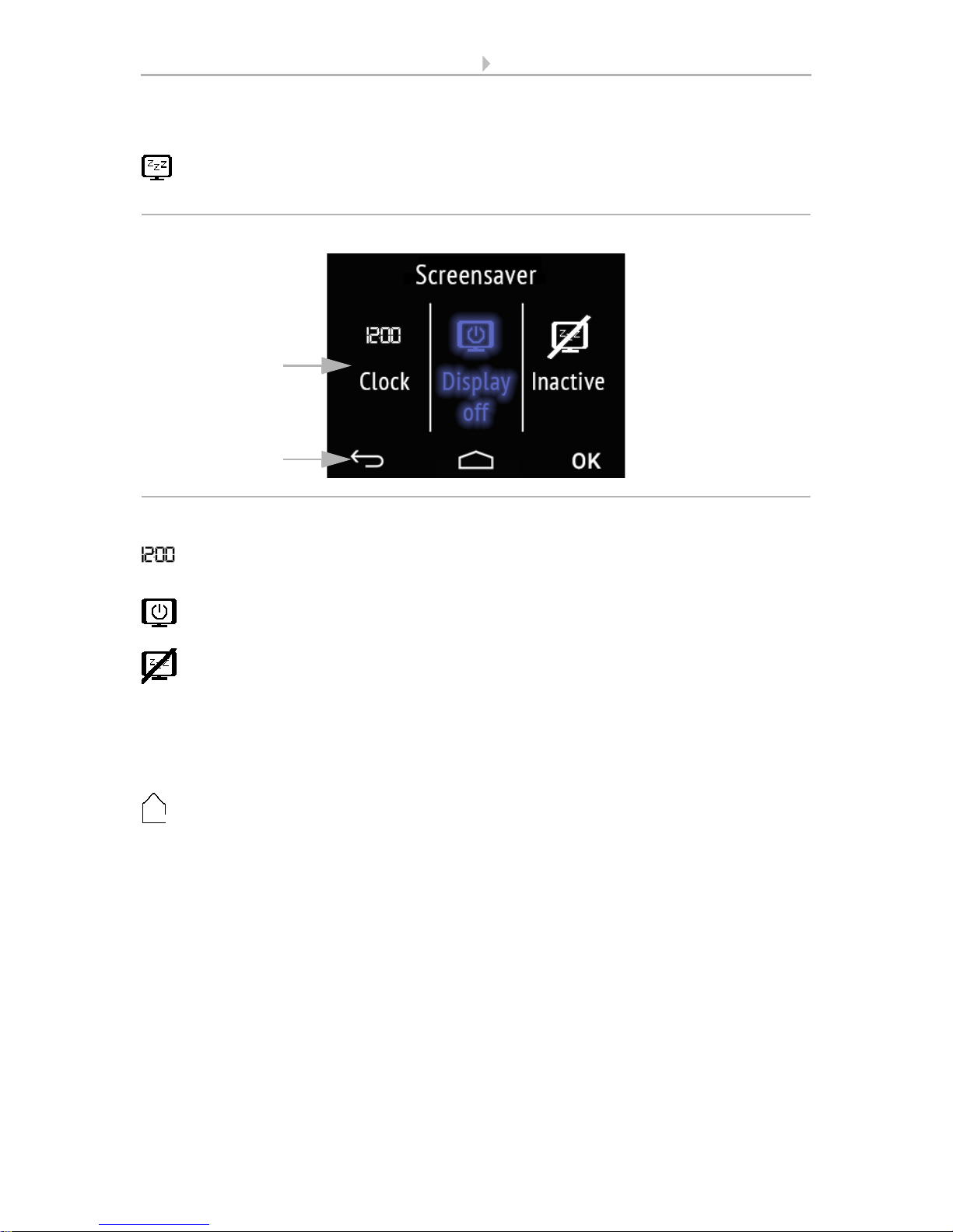
Screen saver
Tap the screen saver symbol to select the type of screen saver or switch the
screen saver off.
(1) Select the desired screen saver function. The selected function is shown in blue.
Screen saver "clock" becomes active after the period set in the ETS.
Screen is switched off after the period set in the ETS.
Screen saver not active
(2) The navigation bar keys take you back to the start page or let you confirm the
changes with OK.
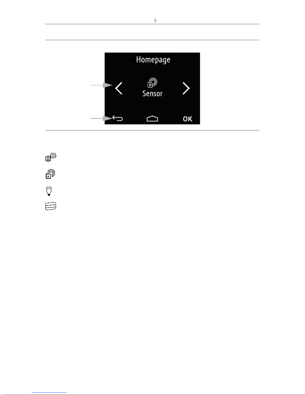
Start display
Tap the start page symbol to modify the start page.
The start page is the menu that is shown after startup and pressing the house symbol.
One may also set the display screen to jump back to the start screen by itself if the
screen has not been touched for a certain period of time (see next setting).
Fig. 7: Menu Settings > Display > Screen saver
2
1
18 Operating the device via the touch display
Sensor with Cala KNX display • Version: 13.03.2017 • Technical changes and errors excepted.
(1) Switch to the desired start page menu with the left/right arrow keys. The name of
the menu and the symbol are displayed.
Settings
Sensor system (measured value display)
Light 1-3
Drive 1-3
Only those menus are shown that have been activated for display in the ETS (see chapter Menus, page 47).
(2) The navigation bar keys take you back to the start page or allow you to confirm the
changes with OK.
Fig. 8: Menu Settings > Display > Screen saver
2
1

19 Operating the device via the touch display
Sensor with Cala KNX display • Version: 13.03.2017 • Technical changes and errors excepted.
Switch to start page
Tap on the symbol "Switch to start page" in order to switch automatic return to
the start page on or off.
(1)Activate or deactivate the function by tapping on the words No or Yes or drag the
slide bar to the desired setting. The wait time for the switch is pre-set in the ETS (see
chapter Display, page 45).
(2) The navigation bar keys take you back to the start page or allow you to confirm the
changes with OK.
5.2.2. Button tone
Tap on the loudspeaker symbol to call up the button tone settings.
The button tone may be emitted as an acoustic acknowledgement when a touch
key is activated.
(1)Activate or deactivate the function by tapping on the words Off or On or drag the
slide bar to the desired setting.
Fig. 9: Menu Settings > Display > Screen saver
2
1
Fig. 10: Menu Settings > Button tone
2
1
20 Operating the device via the touch display
Sensor with Cala KNX display • Version: 13.03.2017 • Technical changes and errors excepted.
(2) The navigation bar touch keys allow you to
cancel and return to the previous menu level without saving
jump to the start page without saving
confirm and return to the previous menu level after saving from the settings
screens
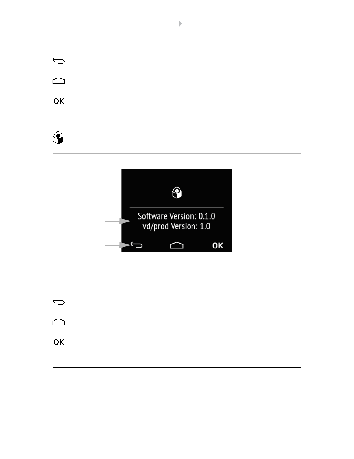
5.2.3. Version
Tap on the software symbol to show the device version.
(1) This shows the software version and the application version (VD or KNXprod file)
that is needed for the device.
(2) The navigation bar touch keys allow you to
cancel and return to the previous menu level without saving
jump to the start page without saving
confirm and return to the previous menu level after saving from the settings
screens
5.3. Sensor system (measured value display)
The display of measured values on the device is only possible if the "Sensor system"
has been activated in the ETS setting item "Menus".
Menus, page 47.
Fig. 11: Menu Settings > Version
2
1
21 Operating the device via the touch display
Sensor with Cala KNX display • Version: 13.03.2017 • Technical changes and errors excepted.
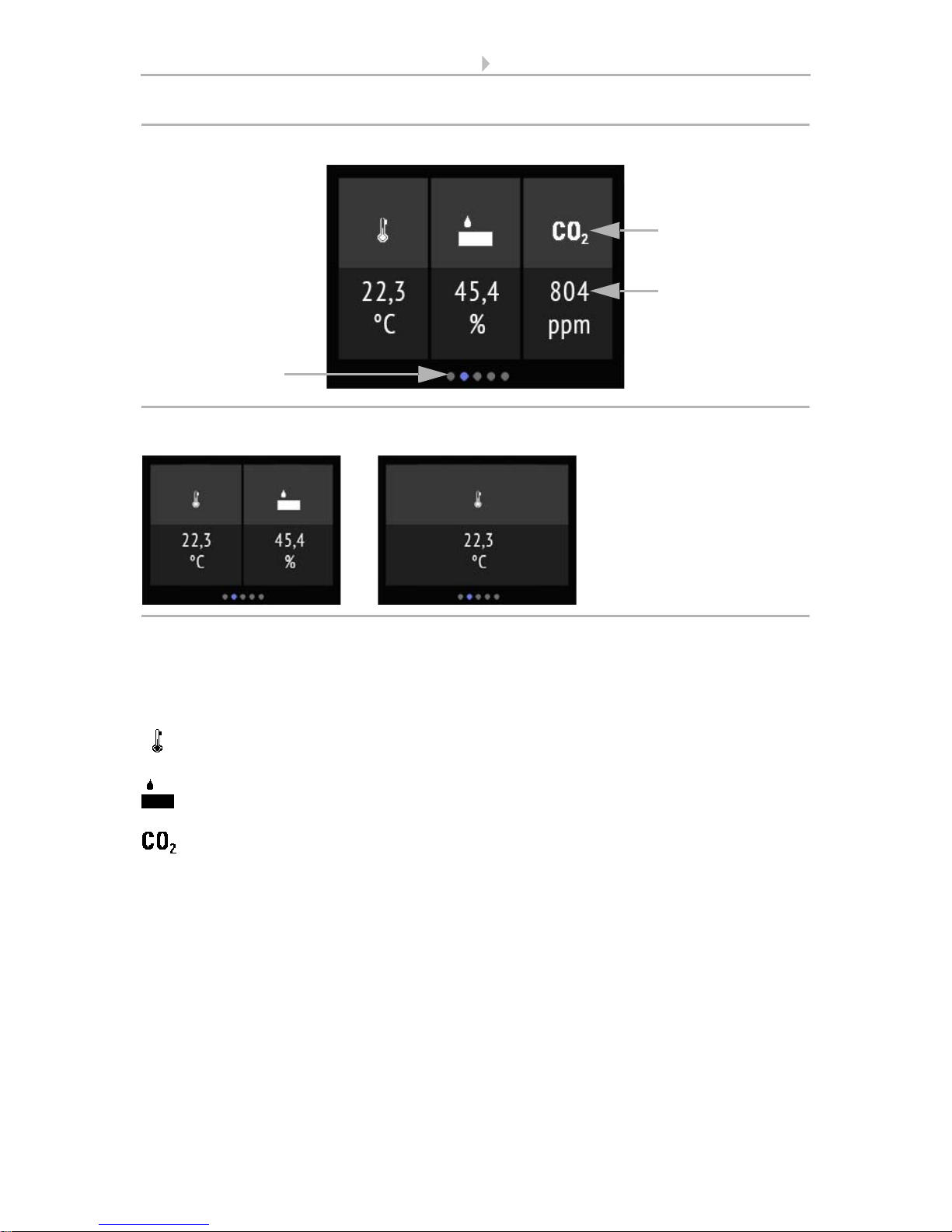
On the display page "Sensor system, the current measuring values from the sensor (2)
are displayed underneath the (1) symbols for the measuring variables. Depending on
the model, this can be temperature, air humidity and/or the carbon dioxide level of the
air.
The temperature is displayed in degree Celsius.
The relative air humidity is displayed in %.
The CO
2
content in the air is shown in ppm (parts per million),
with 1000 ppm = 0,1%.
CO
2
levels between 300 ppm and 1000 ppm are referred to as fresh air. From 1000 ppm
to 2000 ppm the air is considered stale.
In all cases, this is the measuring value from the device.
(3) The dots on the lower display edge symbolise the individual menu pages in the
main menus. The currently selected position is marked in colour. Swipe to the left or
right on the display to show the other menu pages.
1
Fig. 12: Menu Sensor system, example Cala KNX AWS/TH
2
3
Fig. 13 a+b: Sensor system menu: Cala KNX TH, Cala KNX T
22 Operating the device via the touch display
Sensor with Cala KNX display • Version: 13.03.2017 • Technical changes and errors excepted.
5.4. Temperature control
The manual temperature setting on the device is only possible if "Temperature control"
has been activated in the ETS setting item "Menus".
Menus, page 47 and Temperature control, page 48.
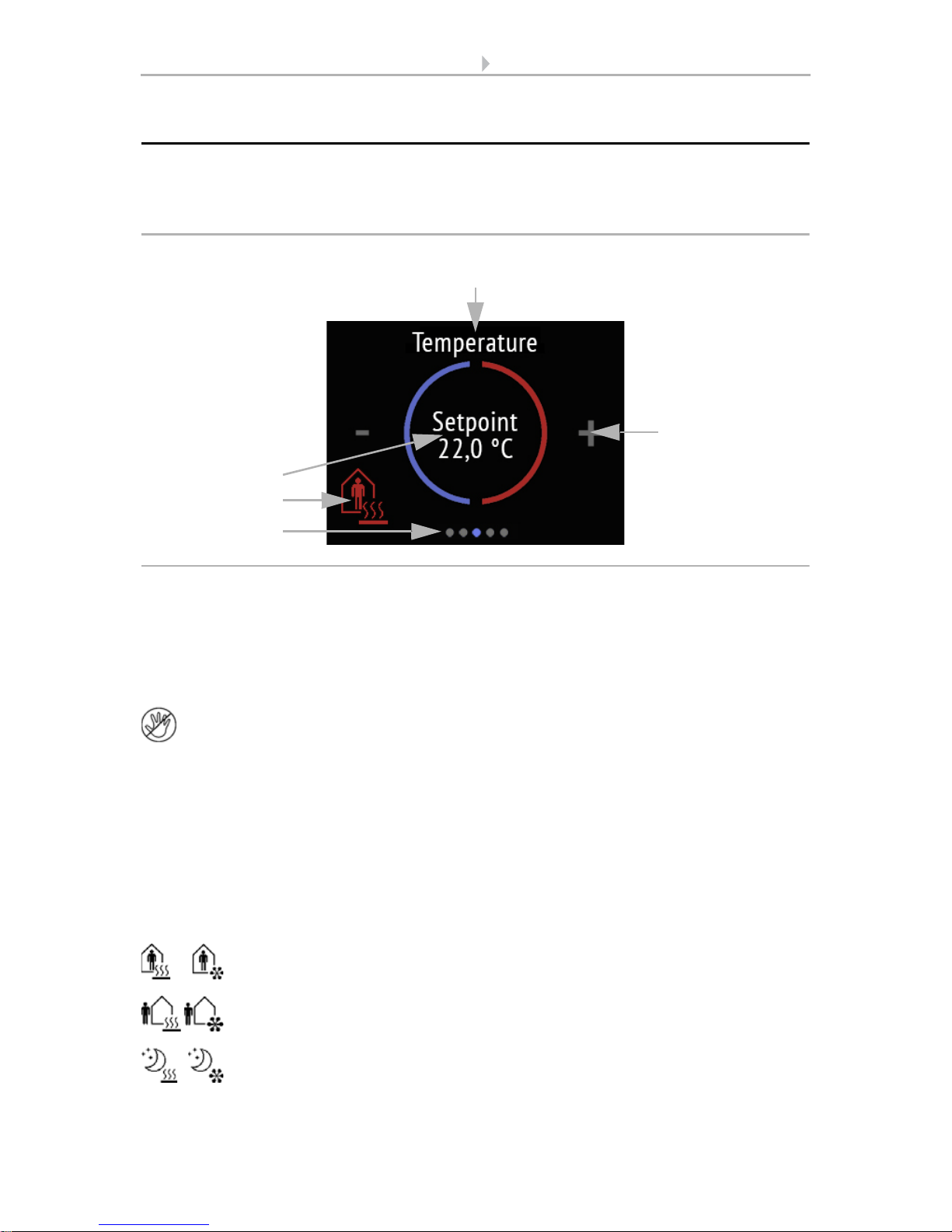
The display page "temperature control" shows
(1) name, (2) current nominal value and, if approved in the ETS, also (3) the current
mode.
(4) The nominal value for the current mode can be adjusted by tapping on the minus
and/or plus symbol.
If the manual modification of the nominal value is blocked in one mode, the symbol "Manual blocked" is briefly shown when an attempt is made to modify the
value.
(3) Tapping on the mode symbol displays the temperature control modes that have
been approved for display selection in the ETS. The current mode is shown in red. In
order to select a different mode, first switch to the symbol of the desired mode by tapping. Then remain on the symbol a little longer. If the button tone is active, you will
receive an acoustic feedback. The mode is now active, and the colour for this symbol
changed from white to red.
The modes change in the following sequence:
Comfort (day, present), heating and/or cooling
Standby (day, brief absence), heating and/or cooling
Eco (night), heating and/or cooling active
1
3
4
2
Fig. 14: Temperature control menu:
5

23 Operating the device via the touch display
Sensor with Cala KNX display • Version: 13.03.2017 • Technical changes and errors excepted.
Building protection (prolonged absence, e.g. vacation), heating and/or
cooling active
The small additional symbol shows whether heating or cooling is active at the current
room temperature (use depends on the connected system).
As long as Eco mode is active, there is an additional symbol for "comfort extension". This option may also be blocked in the ETS (symbol does not appear for
selection).
Remain on the comfort extension symbol for a little longer in order to briefly switch
back to comfort operation. This allows the user to maintain the nominal comfort value
for a longer time, e.g. when having guests. The duration of this comfort extension period is set in the ETS. The remaining time is shown next to the symbol. After the comfort extension period is terminated, the system returns to Eco mode.
(5) The dots on the lower display edge symbolise the individual menu pages in the
main menus. The currently selected position is marked in colour. Swipe to the left or
right on the display to show the other menu pages.
5.5. Light
The manual temperature setting on the device is only possible if "Light" has been activated in the ETS setting item "Menus". The maximum number of light pages is three.
Menus, page 47 and Light 1-3, page 49
Depending on the type of lamp and the settings made in the ETS, the display page
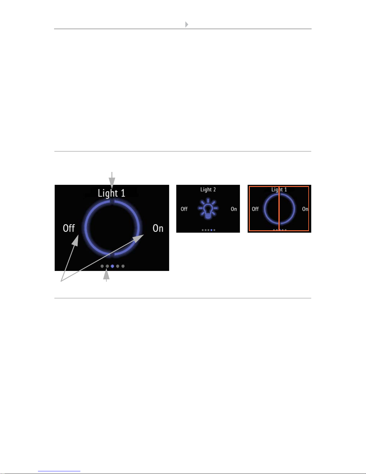
"Light" shows various elements.
Switching over an On/Off area
1
3
Fig. 15: Light menu, an area
2
Light bulb symbol Touch area (marked
in red)
Light switch (tap or
touch for longer to
dim)
Symbol
Circle
24 Operating the device via the touch display
Sensor with Cala KNX display • Version: 13.03.2017 • Technical changes and errors excepted.
If Switching via an area On/Off has been selected,
(1) name and (2) an area with the selected symbol are shown. The symbol is grey when
switched off, and blue when on.
The area switches between on and off. If dimming is set in addition, touch the area for
longer to dim. This process is shown by repeated dimming of the symbol. When dimming, any new contact also switches, i.e. the dimming increases in brightness or decreases alternately.
(3) The dots on the lower display edge symbolise the individual menu pages in the
main menus. The currently selected position is marked in colour. Swipe to the left or
right in this area to show the other menu pages.
Switching via two areas On - Off
If Switching via two areas On - Off has been selected,
(1) name and (2) two areas with the selected symbol are shown. The symbol is grey
when switched off, and blue when on.
Tap on the left part of the screen to switch off the light. Tap on the right part to switch
on.
1
4
Fig. 16: Light menu, two areas (switching)
2
Light bulb symbol Touch areas (marked
in red)
Light switch (tap)
Symbol
Circle
25 Operating the device via the touch display
Sensor with Cala KNX display • Version: 13.03.2017 • Technical changes and errors excepted.
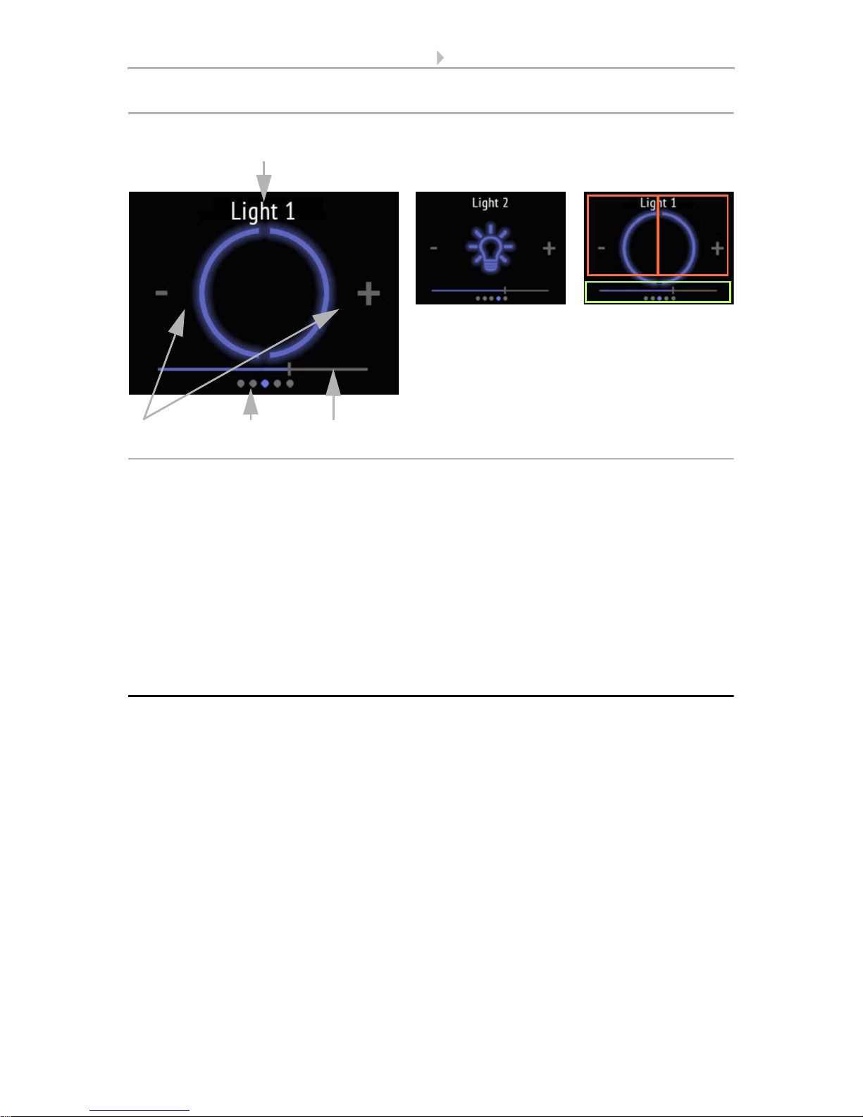
(2) If additional dimming is possible, a minus and a plus symbol are shown. Touching
the left part of the screen (-) dims down. Touching the right part (+) dims up.
(3) Alternatively, swipe left (darker) or right (brighter) on the slider bar that is shown in
the lower part of the display. The slide bar position shows the current brightness of the
lamp in percent.
(4) The dots on the lower display edge symbolise the individual menu pages in the
main menus. The currently selected position is marked in colour. Swipe to the left or
right in the top half of the display to show the other menu pages.
5.6. Drive (shading, window)
Manual operation setting of shading or windows on the device is only possible if
"Drive" has been activated in the ETS setting item "Menus". The maximum number of
drive pages is three.
Menus, page 47 and Drive 1-3, page 50
1
4
Fig. 17: Light menu, two areas (dimming)
32
Light bulb symbol Touch areas
a Light switch/
Dimming (marked in
red, tap)
b slide bar (marked in
green, swipe)
Symbol
Circle
a
b
26 Operating the device via the touch display
Sensor with Cala KNX display • Version: 13.03.2017 • Technical changes and errors excepted.
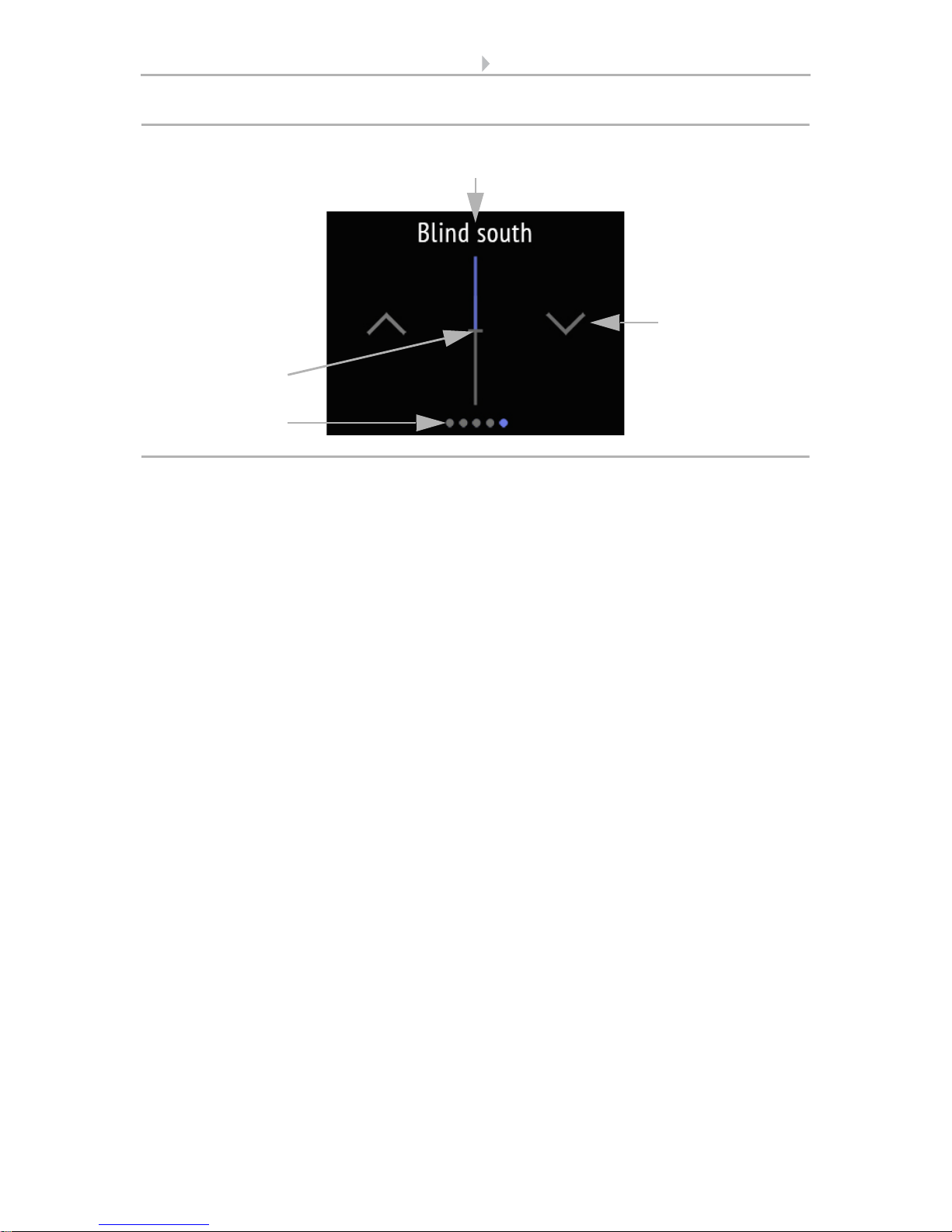
The display page "Drive" is always shown next to the
(1) name (always (2) two keys for left up right down, as wells as (3) a slide bar.
The key reaction (standard, inverted, comfort, dead man) can be set in the ETS.
Drive 1-3, page 50
The slide bar allows you to quickly adjust the movement position. This change does
not influence the slat position of slat shutters. The slide bar position shows the current
movement position in percent.
(4) The dots on the lower display edge symbolise the individual menu pages in the
main menus. The currently selected position is marked in colour. Swipe to the left or
right on the display to show the other menu pages.
1
2
Fig. 18: Drive menu
3
4
27 Transfer protocol
Sensor with Cala KNX display • Version: 13.03.2017 • Technical changes and errors excepted.
6. Transfer protocol
Units:
Temperatures in degrees Celsius
Air humidity in %
Absolute air humidity in g/kg and/or g/m
3
CO2 content in ppm
Variables in %
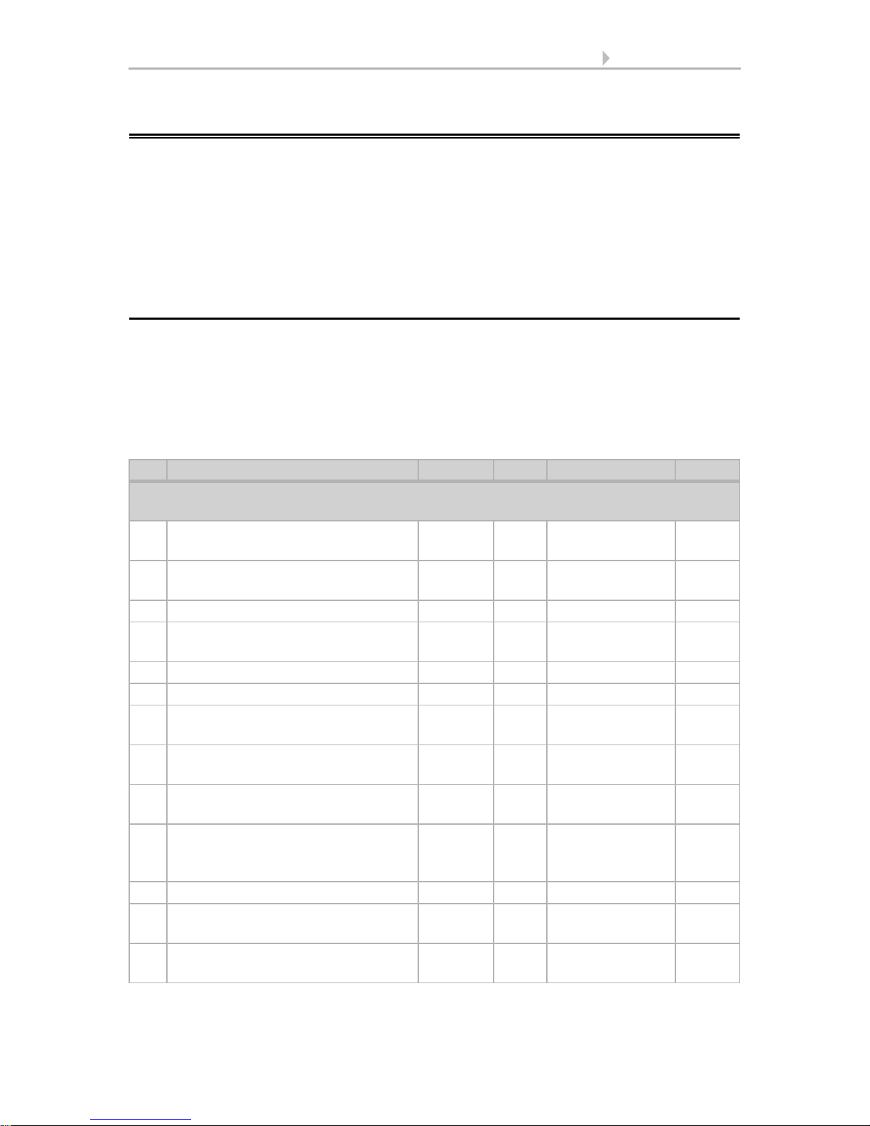
6.1. List of all communications objects
Abbreviation flags:
C Communication
R Read
WWrite
T Transfer
UUpdate
No. Text Function Flags DPT type Size
Display and user interfaces (objects 1-55)
for all models
1 Software version Output R-CT [217,001]
DPT_Version
2 bytes
21 Date / time Input -WCT [19.001] DPT_-
DateTime
8 bytes
22 Date Input -WCT [11.1] DPT_Date 3 bytes
23 Time Input -WCT [10.1] DPT_-
TimeOfDay
3 bytes
25 Screen brightness in % Input RWC- [5.1] DPT_Scaling 1 byte
26 Screen save (1=ON | 0=OFF) Input RWC- [1.1] DPT_Switch 1 bit
27 Screen saver illumination (1=ON |
0=OFF)
Input RWC- [1.1] DPT_Switch 1 bit
28 Screen saver wait time in seconds Input RWC- [7.005] DPT_-
TimePeriodSec
2 bytes
29 Screen no touch wait time in
seconds
Input RWC- [7.005] DPT_-
TimePeriodSec
2 bytes
30 Display language Input RWC- [234.001]
DPT_LanguageCodeAlpha2_ASCII
2 bytes
31 Button tone (1=ON | 0=OFF) Input RWC- [1.1] DPT_Switch 1 bit
34 Switch Light 1 on/off Input/
Output
RWCT [1.1] DPT_Switch 1 bit
35 Dim Light 1 Output R-CT [3.7] DPT_Con-
trol_Dimming
4 bit
28 Transfer protocol
Sensor with Cala KNX display • Version: 13.03.2017 • Technical changes and errors excepted.
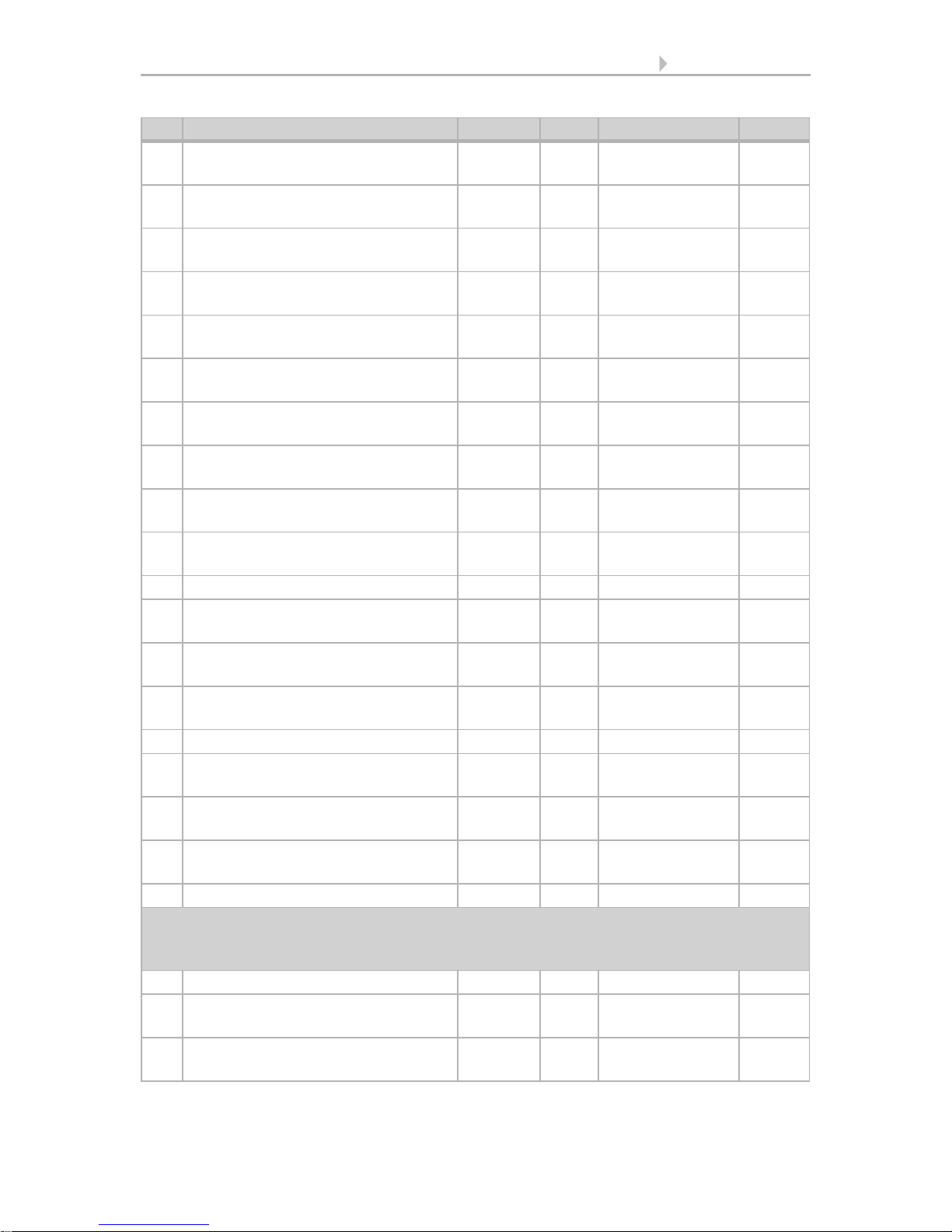
36 Light 1 brightness Input/
Output
RWCT [5.1] DPT_Scaling 1 byte
37 Switch Light 2 on/off Input/
Output
RWCT [1.1] DPT_Switch 1 bit
38 Dim Light 2 Output R-CT [3.7] DPT_Con-
trol_Dimming
4 bit
39 Light 2 brightness Input/
Output
RWCT [5.1] DPT_Scaling 1 byte
40 Switch Light 3 on/off Input/
Output
RWCT [1.1] DPT_Switch 1 bit
41 Dim Light 3 Output R-CT [3.7] DPT_Con-
trol_Dimming
4 bit
42 Light 3 brightness Input/
Output
RWCT [5.1] DPT_Scaling 1 byte
44 Drive 1 long-term Output --CT [1.8] DPT_Up-
Down
1 bit
45 Drive 1 short-term Output --CT [1.8] DPT_Up-
Down
1 bit
46 Drive 1 movement position Input/
Output
RWCT [5.1] DPT_Scaling 1 byte
47 Drive 1 slat position Input -WCT [5.1] DPT_Scaling 1 byte
48 Drive 2 long-term Output --CT [1.8] DPT_Up-
Down
1 bit
49 Drive 2 short-term Output --CT [1.8] DPT_Up-
Down
1 bit
50 Drive 2 movement position Input/
Output
RWCT [5.1] DPT_Scaling 1 byte
51 Drive 2 slat position Input -WCT [5.1] DPT_Scaling 1 byte
52 Drive 3 long-term Output --CT [1.8] DPT_Up-
Down
1 bit
53 Drive 3 short-term Output --CT [1.8] DPT_Up-
Down
1 bit
54 Drive 3 movement position Input /
Output
RWCT [5.1] DPT_Scaling 1 byte
55 Drive 3 slat position Input -WCT [5.1] DPT_Scaling 1 byte
Temperature sensor (objects 61-97)
for Cala KNX AQS/TH (item no. 70603, 70608), Cala KNX TH (item no. 70602, 70607),
Cala KNX T (no. 70601, 70606)
61 Temperature sensor: Malfunction Output R-CT [1.1] DPT_Switch 1 bit
62 Temperature sensor: Measured
value external
Input -WCT [9.1] DPT_Val-
ue_Temp
2 bytes
63 Temperature sensor: Measured
value
Output R-CT [9.1] DPT_Val-
ue_Temp
2 bytes
No. Text Function Flags DPT type Size
 Loading...