

Elsner 70387 Installation And Adjustment Manual
Installation and Adjustment
Item number 70387
EN
Vari KNX GPS
GPS Receiver
1 Contents
Elsner Elektronik GmbH • Sohlengrund 16 • 75395 Ostelsheim • Germany
GPS Receiver Vari KNX GPS • from ETS programme version 1.0
Status:22.08.2017 • Errors excepted. Subject to technical changes.
1. Description ........................................................................................... 3
1.0.1. Scope of delivery .......................................................................................... 3
1.1. Technical specification ............................................................................................. 3
2. Installation and start-up ....................................................................... 4
2.1. Installation notes ...................................................................................................... 4
2.2. Installation location .................................................................................................. 4
2.3. Device design ........................................................................................................... 6
2.4. Installing the device ................................................................................................. 6
2.4.1. Preparation for installation .......................................................................... 6
2.4.2. Fitting the lower part of the housing with mounting ................................. 7
2.4.3. Connection .................................................................................................... 9
2.4.4. Completing the installation .......................................................................... 9
3. Addressing the device .......................................................................... 9
4. Maintenance ....................................................................................... 10
5. Transfer protocol ............................................................................... 11
5.1. List of all communication objects ......................................................................... 11
6. Parameter setting .............................................................................. 19
6.1. Behaviour on power failure/ restoration of power .............................................. 19
6.1.1. Malfunction objects .................................................................................... 19
6.1.2. General settings .......................................................................................... 19
6.2. GPS .......................................................................................................................... 19
6.3. Location ................................................................................................................... 20
6.4. Sun position ............................................................................................................ 22
6.5. Weekly timer ........................................................................................................... 23
6.5.1. Weekly timer period 1-24 ........................................................................... 23
6.6. Calendar timer ........................................................................................................ 24
6.6.1. Calendar clock Period 1-4 ........................................................................... 25
2 Clarification of signs
This manual is amended periodically and will be brought into line with new software
releases. The change status (software version and date) can be found in the contents footer.
If you have a device with a later software version, please check
www.elsner-elektronik.de in the menu area "Service" to find out whether a more up-todate version of the manual is available.
Clarification of signs used in this manual
Installation, inspection, commissioning and troubleshooting of the device
must only be carried out by a competent electrician.
Safety advice.
Safety advice for working on electrical connections, components,
etc.
DANGER!
... indicates an immediately hazardous situation which will lead to
death or severe injuries if it is not avoided.
WARNING!
... indicates a potentially hazardous situation which may lead to
death or severe injuries if it is not avoided.
CAUTION!
... indicates a potentially hazardous situation which may lead to
trivial or minor injuries if it is not avoided.
ATTENTION!
... indicates a situation which may lead to damage to property if it is
not avoided.
ETS In the ETS tables, the parameter default settings are marked by
underlining.

3 Description
GPS Receiver Vari KNX GPS • Status: 22.08.2017 • Errors excepted. Subject to technical changes.
1. Description
The GPS Receiver Vari KNX GPS for the KNX building system receives the GPS signal for time and location and uses it to compute the position of the sun (azimuth and
elevation).
The compact housing of the Vari KNX GPS accommodates the receiver, evaluation
circuits and bus-coupling electronics.
Functions:
• GPS receiver, outputting the current time and location coordinates. The GPS
Receiver Vari KNX GPS also computes the position of the sun (azimuth and
elevation)
• Weekly and calendar time switch: All time switching outputs can be used
as communication objects.
The weekly time switch has 24 periods. Each period can be configured either
as an output or as an input. If the period is an output, then the switching time
is set per parameter or per communication object.
The calendar time switch has 4 periods. Two on/off switching operations,
which are executed daily, can be set for each period
Configuration is made using the KNX software ETS. The product file can be downloaded from the Elsner Elektronik website on www.elsner-elektronik.de in the “Service” menu.
1.0.1. Scope of delivery
• Receiver
• Stainless steel installation band for pole installation
• 4×50 mm stainless steel roundhead screws and 6×30 mm dowels for wall
mounting. Use fixing materials that are suitable for the base!
1.1. Technical specification
Housing Plastic
Colour White / Translucent
Assembly Surface mount
Protection category IP 44
Dimensions approx. 65 × 80 × 30 (W × H × D, mm)
Weight approx. 60 g
Ambient temperature Operation -30…+50°C, Storage -30…+70°C
Operating voltage KNX bus voltage
Bus current max. 20 mA
Data output KNX +/- bus connector terminal
BCU type Integrated microcontroller
PEI type 0

4 Installation and start-up
GPS Receiver Vari KNX GPS • Status: 22.08.2017 • Errors excepted. Subject to technical changes.
The product conforms with the provisions of EU directives.
2. Installation and start-up
2.1. Installation notes
Installation, testing, operational start-up and troubleshooting should
only be performed by an electrician.
CAUTION!
Live voltage!
There are unprotected live components inside the device.
• National legal regulations are to be followed.
• Ensure that all lines to be assembled are free of voltage and take
precautions against accidental switching on.
• Do not use the device if it is damaged.
• Take the device or system out of service and secure it against
unintentional use, if it can be assumed, that risk-free operation is no
longer guaranteed.
The device is only to be used for its intended purpose. Any improper modification or
failure to follow the operating instructions voids any and all warranty and guarantee
claims.
After unpacking the device, check it immediately for possible mechanical damage. If it
has been damaged in transport, inform the supplier immediately.
The device may only be used as a fixed-site installation; that means only when assembled and after conclusion of all installation and operational start-up tasks and only in
the surroundings designated for it.
Elsner Elektronik is not liable for any changes in norms and standards which may occur
after publication of these operating instructions.
2.2. Installation location
The GPS Receiver Vari KNX GPS must be installed outside.
Group addresses max. 2000
Assignments max. 2000
Communication objects: 150
5 Installation and start-up
GPS Receiver Vari KNX GPS • Status: 22.08.2017 • Errors excepted. Subject to technical changes.
Magnetic fields, transmitters and interference fields from electrical consumers (e.g. fluorescent lamps, neon signs, switch mode power supplies etc.) can block or interfere
with the reception of the GPS signal.
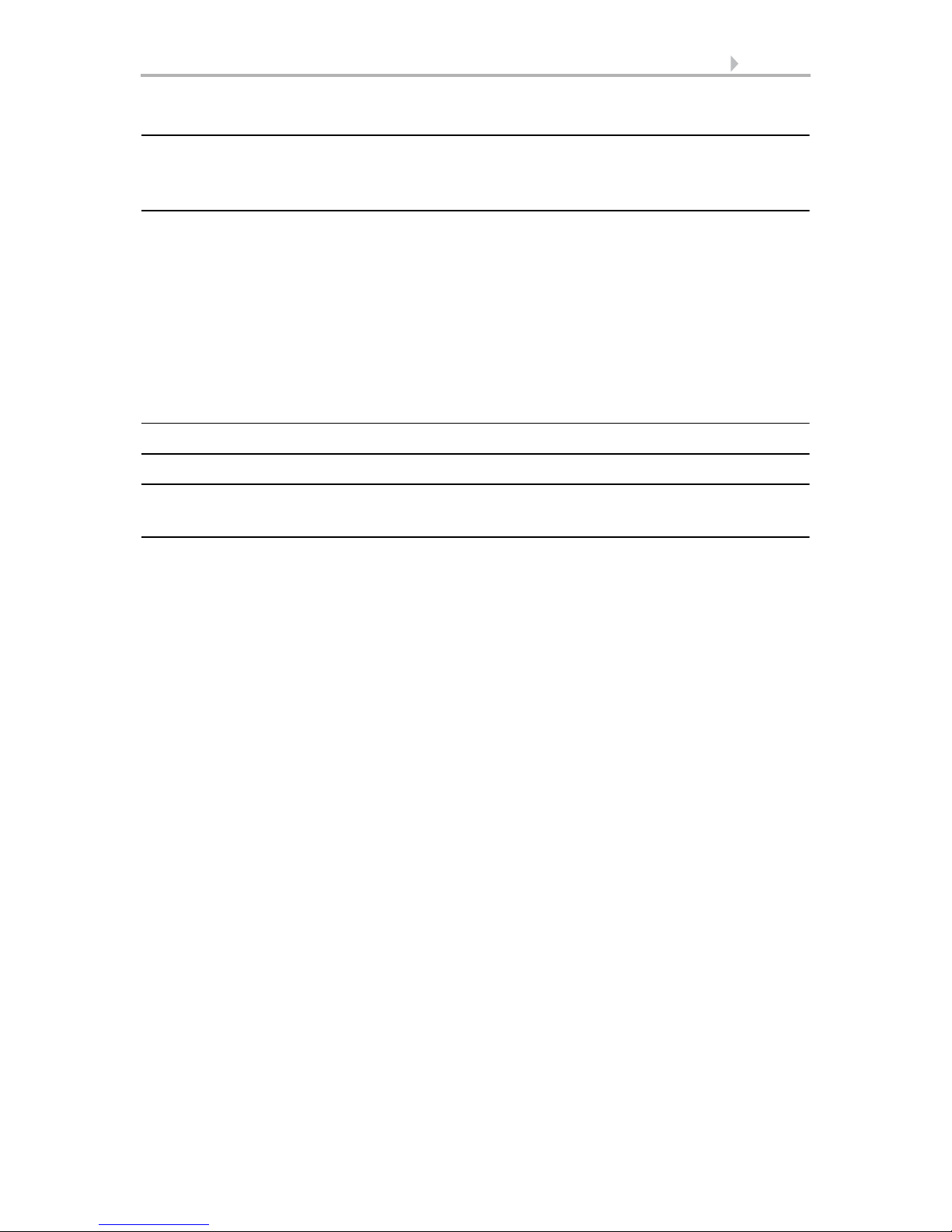
Fig. 1
The device must be attached to a vertical wall
(or a pole).
wall
or
pole
90°
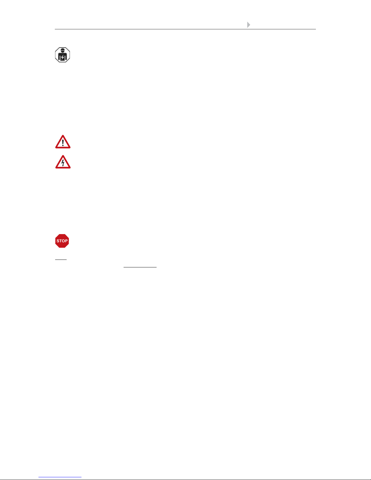
Fig. 2
The device must be mounted in the horizontal
(transverse) direction.
Horizontal

6 Installation and start-up
GPS Receiver Vari KNX GPS • Status: 22.08.2017 • Errors excepted. Subject to technical changes.
2.3. Device design
2.4. Installing the device
ATTENTION!
Even a few drops of water can damage the device electronics.
• Do not open the device if water (e.g. rain) can get into it.
2.4.1. Preparation for installation
2
Fig. 3
1 Semi-transparent cover
(GPS receiver below)
2 Position of the Signal LED (un-
der the cover). LED is freely controlled via two objects
3 Position of the programming
LED (under the cover)
4 Lower part of housing
5 Programming key on the bottom
of the housing (recessed), see
Device design, page 6
6 Wall/Pole holder
3
6
5
4
1
Fig. 4
The cover and lower part of the housing are
connected together. Pull both parts apart in a
straight line.

7 Installation and start-up
GPS Receiver Vari KNX GPS • Status: 22.08.2017 • Errors excepted. Subject to technical changes.
2.4.2. Fitting the lower part of the housing with mounting
Now, first of all, assemble the lower part of the housing with the integrated mounting
for wall or pole installation.
Wall installation
Use fixing materials (dowels, screws) that are suitable for the base.
Fig. 5
The device is installed with two screws. Break
off the two longitudinal holes in the housing.
Longitudinal holes
Fig. 6 a+b
a) If the power lead is to be hidden when in-
stalled, it must emerge from the wall in
the vicinity of the rear of the housing
(marked area).
b) If the power lead is to be surface-mount-
ed, the cable guide is broken off. The lead
is then fed into the device from the bottom of the housing.
Cable guide
8 Installation and start-up
GPS Receiver Vari KNX GPS • Status: 22.08.2017 • Errors excepted. Subject to technical changes.
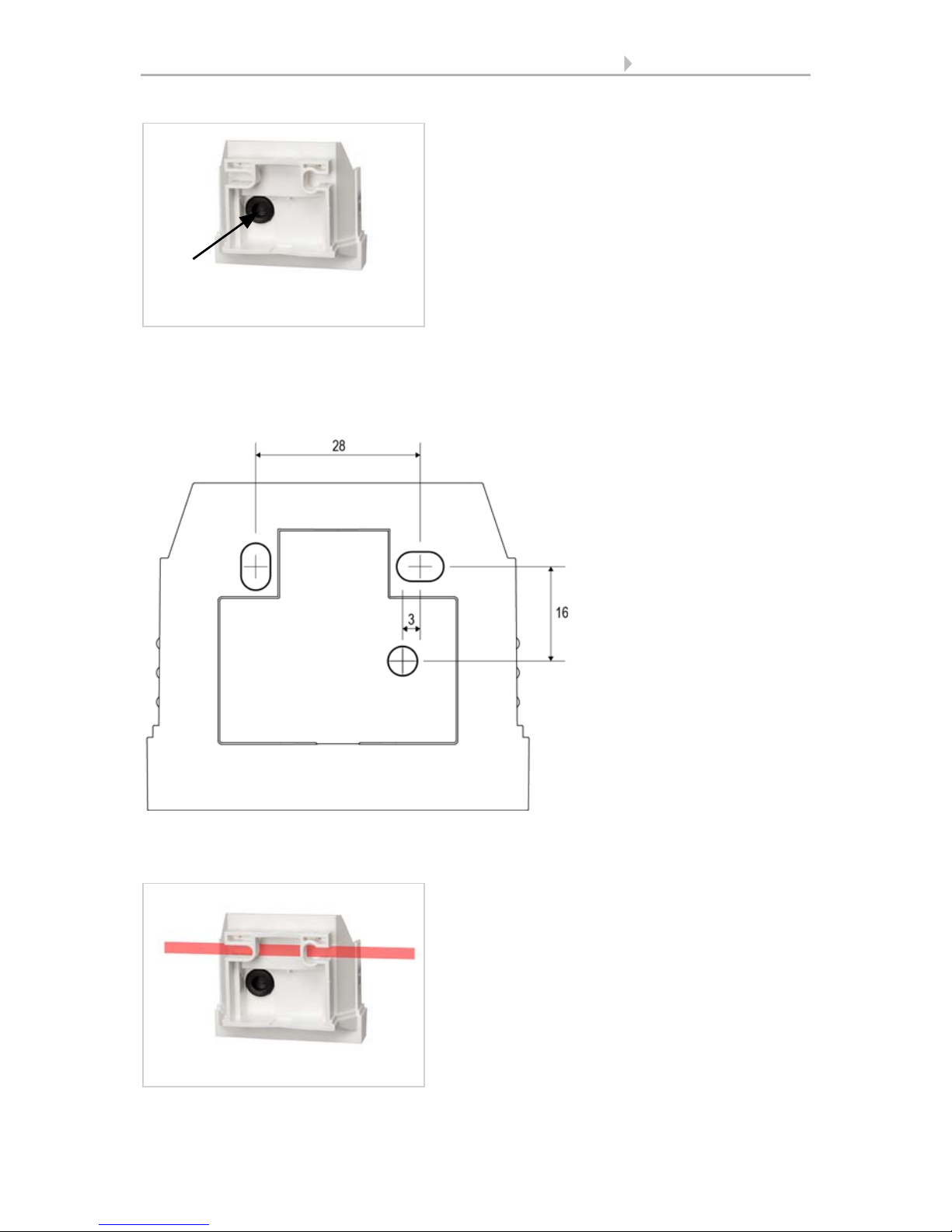
Drilling plan
ATTENTION! The print out of the data sheet doesn‘t have original size!
A separate, dimensionally correct drilling plan is included ex works and this can be
used as a template.
Pole installation
The device is installed on the pole with the enclosed stainless steel mounting band.
Fig. 7
Feed the power lead through the rubber gasket.
Rubber
gasket
Fig. 8
Dimensions in mm. Variations are possible for technical reasons
A/B2× longitudinal holes
8 mm × 5 mm
C Position of the cable
outlet (rubber gasket)
in the housing
AB
C
Fig. 9
Feed the mounting band through the eyelets
in the lower part of the housing.
 Loading...