

Elsner AQS/TH PF, 40115, TH PF-U, TH PF, 40100 Installation And Adjustment Manual
...
EN
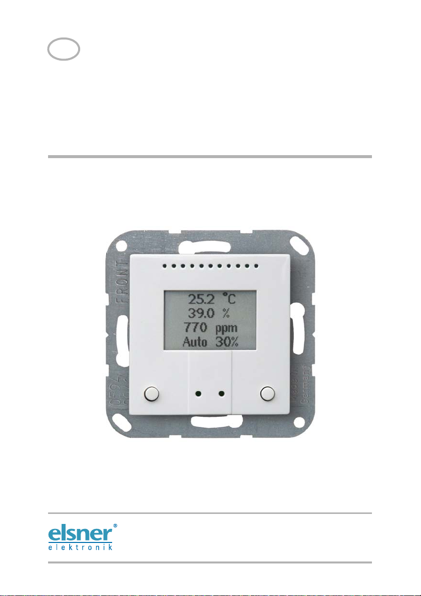
AQS/TH PF
Indoor Sensor and Ventilation Control
Item number 40115
Installation and Adjustment


1 Content
1. Description ........................................................................................... 3
1.0.1. Deliverables ................................................................................................... 3
1.1. Technical data ........................................................................................................... 3
1.1.1. Measuring accuracy ...................................................................................... 4
2. Installation and start-up ....................................................................... 5
2.1. Installation notes ...................................................................................................... 5
2.2. Installation location .................................................................................................. 5
2.3. Sensor connection and design ................................................................................ 6
2.3.1. Housing .......................................................................................................... 6
2.3.2. Connection board ......................................................................................... 7
2.3.3. Wiring diagram Window .............................................................................. 8
2.3.4. Wiring diagram Ventilation Units ................................................................ 9
2.3.5. Wiring diagram smoke and heat extraction system ................................ 10
2.4. Sensor assembly .................................................................................................... 10
2.5. Notes on mounting and commissioning .............................................................. 10
3. Basic setting ...................................................................................... 11
4. Adjust automatic ventilation system ................................................. 16
5. Use of the device, manual airing ....................................................... 23
5.1. Standard display .................................................................................................... 23
5.2. Manual operation ................................................................................................... 24
5.2.1. Key functions ............................................................................................... 24
5.3. Operation modes .................................................................................................... 25
Elsner Elektronik GmbH • Sohlengrund 16 • 75395 Ostelsheim • Germany
Ventilation Control AQS/TH PF • from software version 1.0
Status: 31.01.2017 • Subject to technical changes. Errors excepted.

2 Clarification of signs
Installation, inspection, commissioning and troubleshooting of the device
must only be carried out by a competent electrician.
This manual is amended periodically and will be brought into line with new software
releases. The change status (software version and date) can be found in the contents footer.
If you have a device with a later software version, please check
www.elsner-elektronik.de in the menu area "Service" to find out whether a more up-todate version of the manual is available.
Clarification of signs used in this manual
Safety advice.
Safety advice for working on electrical connections, components,
etc.
DANGER!
WARNING!
CAUTION!
ATTENTION!
... indicates an immediately hazardous situation which will lead to
death or severe injuries if it is not avoided.
... indicates a potentially hazardous situation which may lead to
death or severe injuries if it is not avoided.
... indicates a potentially hazardous situation which may lead to
trivial or minor injuries if it is not avoided.
... indicates a situation which may lead to damage to property if it is
not avoided.

3 Description
1. Description
The Ventilation Control AQS/TH PF combines sensor system and control
technology for the ventilation system. Temperature, humidity and CO
are monitored. The device controls a window (open/close in one or two steps) or a
ventilation device (one or two levels) via potential-free outputs.
Two inputs allow an interruption of the automatic system via external signals. A
continuous movement command from a connected hand-held device, a timer or a
blocking function (rain detector or similar) takes precedence.
The housing fits into standard 55 mm switching programmes and is available in two
different colours. The AQS/TH PF is equipped with two buttons for manual control of
the respective window/ventilator and for adjusting the device. The display shows
current measured values and mode and guides through the set-up menus.
Functions:
• Measuring the CO
humidity
• Control of a window of ventilator in one or two steps, threshold values to
be adjusted individually
• Display of current measuring values and mode
• 2 buttons for adjustment and manual control
• 2 inputs for external actuation commands (button, timing, rain detector/
blocking function) with priority in case of continuous signal
level in the air, the temperature and relative air
2
1.0.1. Deliverables
• Housing with display
•CO
sensor unit
2
• Base plate
• 8-wire connecting cable
In addition you need (not included in the deliverables):
• Junction box Ø 60 mm, 42 mm depth
• Frame (for insert 55 x 55 mm), compatible to the switch scheme used in the
building
level of the air
2
1.1. Technical data
Housing Plastic (partially painted)
Colours • bright white (similar to RAL 9016 traffic white)
Mounting Flush mounting
Protection category IP 20
Ventilation Control AQS/TH PF • Version: 31.01.2017 • Technical changes and errors excepted.
• special colours on request
(wall mounting in junction box Ø60 mm, 42 mm depth)

4 Description
Dimensions Housing approx. 55 x 55 (W x H, mm),
Total weight approx. 85 g
Ambient temperature Operation 0…+50°C, storage -10…+60°C
Ambient humidity max. 95% RH, avoid condensation
Operating voltage 24 V DC ±20%
Power consumption max. 16 mA
CO2measuring range 0...2000 ppm
CO
resolution 1 ppm
2
accuracy* ± 50 ppm ± 3% of the measuring value
CO
2
Temperature measuring
range
Temperature resolution 0.1°C
Temperature accuracy* ± 0.5°C at 0...+50°C
Humidity measuring range 0% RH…95% RH
Humidity resolution 0.1%
Humidity accuracy ±7,5% RH at 0...10% RH
Ventilation outputs 2 semi-conductor outputs, open collector
Inputs 2 button inputs (with +24 V supply)
Mounting depth approx. 15 mm,
Base plate approx. 71 x 71 (W x H, mm)
0…+50°C
±4,5% RH at 10...90% RH
±7,5% RH at 90…95% RH
max. 50 V AC/DC, 100 mA
* Please note the information on measuring accuracy below.
The product conforms with the provisions of EU directives.
1.1.1. Measuring accuracy
Follow the instructions in chapter Installation position to avoid sources of interference
and to ensure the specified accuracy of the sensor. To ensure a correct CO
measurement, the device must be installed in a windproof socket.
The indicated accuracy of the CO2 measurement will be achieved after a run-in
period of 24 hours (without interruption of the bus voltage) if the sensor has been in
contact with fresh air (350…450 ppm) at least once in this period. During the warm-up
phase the reading may not be displayed at all or wrongly, or remain frozen at 2001.
After this, the CO
measured value captured during that period (without interruption of the bus voltage)
as a reference for fresh air.
The guarantee the accuracy on a sustained basis, the sensor should be provided with
fresh air at least once in two weeks. This occurs normally during room ventilation.
When measuring temperature, the self-heating of the device is considered by the
electronics. The heating is compensated by reducing the measured temperture by the
self-heating of 0.7°C. The indicated indoor temperature measured value approches the
Ventilation Control AQS/TH PF • Version: 31.01.2017 • Technical changes and errors excepted.
sensor will recalibrate every two weeks by defining the lowest
2
2

5 Installation and start-up
actual room temperature during a 2 hours heating period. Additionally, the
temperature can be adjusted in the basic settings menu.
2. Installation and start-up
2.1. Installation notes
Installation, testing, operational start-up and troubleshooting should
only be performed by an electrician.
CAUTION!
Live voltage!
There are unprotected live components inside the device.
• National legal regulations are to be followed.
• Ensure that all lines to be assembled are free of voltage and take
precautions against accidental switching on.
• Do not use the device if it is damaged.
• Take the device or system out of service and secure it against
unintentional use, if it can be assumed, that risk-free operation is no
longer guaranteed.
The device is only to be used for its intended purpose. Any improper modification or
failure to follow the operating instructions voids any and all warranty and guarantee
claims.
After unpacking the device, check it immediately for possible mechanical damage. If it
has been damaged in transport, inform the supplier immediately.
The device may only be used as a fixed-site installation; that means only when
assembled and after conclusion of all installation and operational start-up tasks and
only in the surroundings designated for
Elsner Elektronik is not liable for any changes in norms and standards which may occur
after publication of these operating instructions.
it.
2.2. Installation location
The Ventilation Control AQS/TH PF are installed flush to the wall surface in a
junction box (R 60 mm, 42 mm deep).
May be installed and operated in dry interior rooms only.
Avoid condensation.
When selecting an installation location, please ensure that the measurement results
are affected as little as possible by external influences. Possible sources of interference
include:
• Direct sunlight
Ventilation Control AQS/TH PF • Version: 31.01.2017 • Technical changes and errors excepted.
6 Installation and start-up
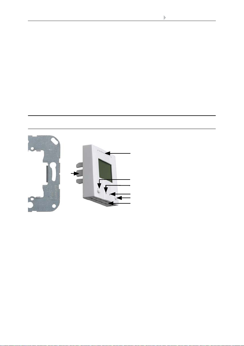
Fig. 1
1 Base plate
2 Catches
3 Openings for air circulation
4 CLOSE/- button
5 CLOSE/- LED (recessed)
6 OPEN/- LED (recessed)
7 OPEN/- button
8 Openings for air circulation
(LOWER)
3
2
4
6
7
5
8
1
• Drafts from windows and doors
• Draft from ducts which lead from other rooms or from the outside to the
junction box in which the sensor is mounted
• Warming or cooling of the building structure on which the sensor is mounted,
e.g. due to sunlight, heating or cold water pipes
• Connection lines and ducts which lead from warmer or colder areas to the
sensor
Measurement variations from such sources of interference must be corrected in the
basic settings menu in order to ensure the specified accuracy of the sensor.
To ensure a correct CO2 measurement, the device must be installed in a windproof
socket.
2.3. Sensor connection and design
2.3.1. Housing
Ventilation Control AQS/TH PF • Version: 31.01.2017 • Technical changes and errors excepted.
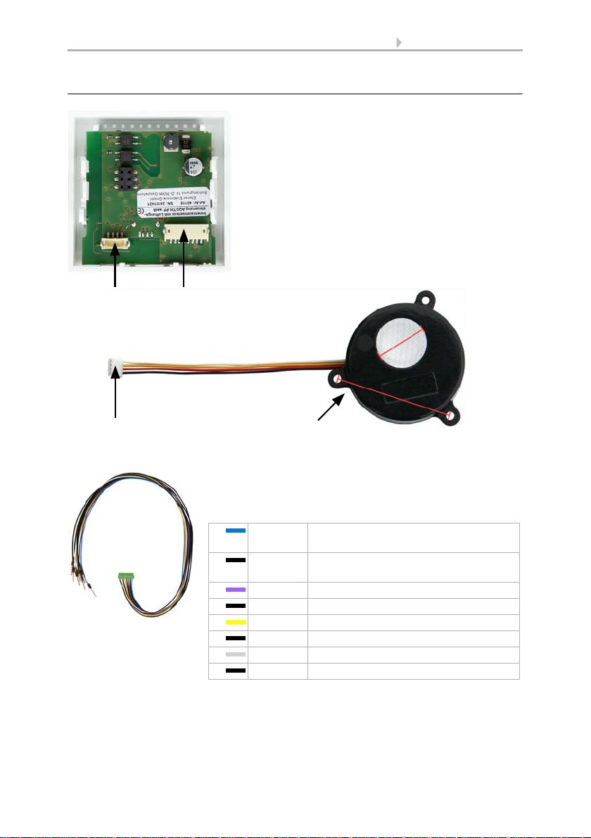
2.3.2. Connection board
Fig. 2
1Slot CO
2
sensor unit
2 Socket for 8-wire connecting cable, see Fig. 4
3Plug CO
2
sensor unit
4CO
2
sensor unit
Cable length of CO
2
sensor approx. 110 mm.
a Hole distance approx. 43 mm
b Membrane diameter approx. 18 mm
2
3
4
a
b
1
Fig. 3
8-wire connecting cable for control outputs, inputs
and operating voltage:
blue Output 2
(OPEN window, Ventilator level 2)
black Output 1
(CLOSE window, Ventilator level 1)
purple Supply voltage for output 1+2
black Input 2 (OPEN/+)
yellow Input 1 (CLOSE/-)
black Supply voltage for input 1+2
white Operating voltage GND
black Operating voltage +24 V
7 Installation and start-up
Ventilation Control AQS/TH PF • Version: 31.01.2017 • Technical changes and errors excepted.
 Loading...