

Page 1
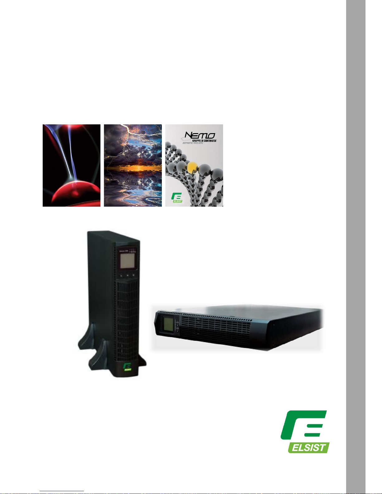
UPServer2.0
ON-LINE DOUBLE CONVERSION
UPServer2.0
On Line Double Conversion 2KVA
Uninterruptible Power Supplies
USER MANUAL
Page 2

UPServer2.0
ON-LINE DOUBLE CONVERSION
Table of Contents
1. INTRODUCTION ........................................................................................................................... 2
2. SAFETY WARNINGS .................................................................................................................... 3
3. INSTALLATION............................................................................................................................. 4
Inspecting the Equipment ....................................................................................................................................4
Unpacking the Cabinet ........................................................................................................................................4
Checking the accessories ...................................................................................................................................4
Rackmount Installation ........................................................................................................................................5
Rackmount converted to Tower Installation ...................................................................................................... 11
4 OPERATION ................................................................................................................................ 15
Control Cover Functions................................................................................................................................... 15
Table 1. Indicator Descriptions ......................................................................................................................... 15
User Settings .................................................................................................................................................... 20
UPS Turn on and Turn off ................................................................................................................................. 28
Start up operation ..................................................................................................................................... 28
Turn on the UPS in line mode ................................................................................................................... 28
Turn on the UPS by DC without mains power .......................................................................................... 28
Turn off operation ...................................................................................................................................... 29
Turn off the UPS in line mode ................................................................................................................... 29
Turn off the UPS by DC without mains power .......................................................................................... 29
UPS self-test/mute test operation. ............................................................................................................ 29
Configuring Battery Settings ............................................................................................................................ 29
5. COMMUNICATION RS232, USB, OPTIONALS AND EPO ....................................................... 30
Installing Communication Options and Control Terminals ............................................................................... 30
Communication Options ................................................................................................................................... 30
RS-232 and USB Communication Ports ................................................................................................... 30
Connectivity Cards .................................................................................................................................... 31
.................................................................................................................................................................. 32
6 UPS MAINTENANCE ................................................................................................................................ 34
UPS and Battery Care ...................................................................................................................................... 34
Storing the UPS and Batteries ......................................................................................................................... 34
Replacing Batteries .......................................................................................................................................... 34
Recycling the Used Battery or UPS ................................................................................................................. 37
7. TECHNICAL SPECIFICATION ................................................................................................... 37
8. TROUBLESHOOTING ................................................................................................................ 39
Page 3
UPServer2.0
ON-LINE DOUBLE CONVERSION
Class B EMC Statements
(High Voltage Models up to 3000 VA)
FCC Part 15
NOTE This equipment has been tested and found to comply with the limits for a Class B digital device,
pursuant to part 15 of the FCC Rules. These limits are designed to provide reasonable protection
against harmful interference in a residential installation. This equipment generates, uses and can
radiate radio frequency energy and, if not installed and used in accordance with the instructions, may
cause harmful interference to radio communications. However, there is no guarantee that
interference will not occur in a particular installation. If this equipment does cause harmful
interference to radio or television reception, which can be determined by turning the equipment off
and on, the user is encouraged to try to correct the interference by one or more of the following
measures:
● Reorient or relocate the receiving antenna.
● Increase the separation between the equipment and the receiver.
● Connect the equipment into an outlet on a circuit different from that to which the receiver is
connected.
● Consult the dealer or an experienced radio/TV technician for help.
Special Symbols
The following are examples of symbols used on the UPS or accessories to alert you to important
information:
RISK OF ELECTRIC SHOCK - Observe the warning associated with the risk of electric shock
symbol.
CAUTION,need your attention
This symbol indicates that you should not discard the UPS or the UPS batteries in the trash. This product contains sealed, lead‐
acid batteries and must be disposed of properly. For more information, contact your local recycling/reuse or hazardous waste center.
This symbol indicates that you should not discard waste electrical or electronic equipment (WEEE) in
the trash. For proper disposal, contact your local recycling/reuse or hazardous waste center.
Page 4
UPServer2.0
ON-LINE DOUBLE CONVERSION
1. Introduction
This UPS protects your sensitive electronic equipment from most common power problems,
including power failures, power sags, power surges, brownouts, line noise, high voltage spikes,
frequency variations, switching transients, and harmonic distortion.
Power outages might occur unexpectedly and power quality can be erratic. These power problems
have potential to corrupt critical data, destroy unsaved work sessions, and damage hardware —
causing hours of lost productivity and expensive repairs.
With the UPS, you can safely eliminate the effects of power disturbances and guard the integrity
of your equipment. Providing outstanding performance and reliability, the UPS's unique benefits
include:
True online double-conversion technology with high power density, utility
frequency independence, and generator compatibility. Output power factor
up to 0.9.
Three segment charging mode to increase battery service life, optimize
recharge time.
Selectable High Efficiency mode of operation.
Cold start function to startup the UPS without utility.
Standard communication options: one RS-232 communication port, one
USB communication port, and relay output contacts or SNMP card.
Power Shedding function may turn off uncritical load in battery backup to
make longer backup time for critical load.
Extended runtime with up to four Extended Battery Modules (EBPs) per UPS.
Emergency shutdown control through the Remote Emergency Power-off
(EPO) port.
The content displayed on the interface is rich. The capacity of the loads and
the battery can be seen directly and the FLASH pictures and fan rotating icon
can be displayed while charging. Enhance, it is easy to know its operation
status. When UPS fails, it can show the fault code; therefore, the UPS can
be repaired as soon as possible by inquiring fault code table.
NOTICE: In the manual, RT is short for Rack-Tower conversion
Rack/Tower convertible LCD design. No matter what angle required, only
pressing the key slightly to reach your perspective needs.
For RT model, it is equipped with hot swappable battery feature needed for
19”rack solution.
RT models in a space-optimizing 2U size fits any standard 19” rack.
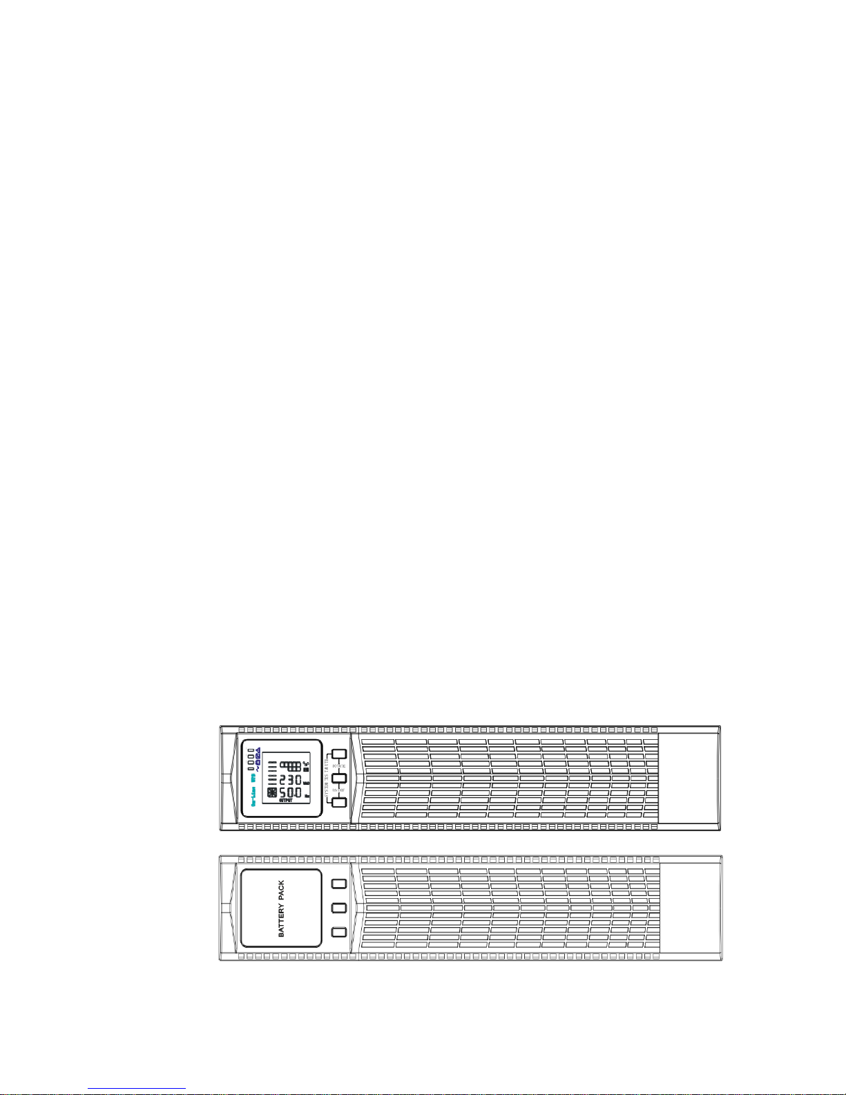
Fig.1
Fig.2
Figure1 – UPS Front View
Figura2 – Battery Expansion “EBP” Front View
Page 5
UPServer2.0
ON-LINE DOUBLE CONVERSION
2. SAFETY WARNINGS
IMPORTANT SAFETY INSTRUCTIONS
SAVE THESE INSTRUCTIONS
This manual contains important instructions that you should follow during
installation and maintenance of the UPS and batteries. Please read all
instructions before operating the equipment and save this manual for future
reference.
DANGER
The UPS contains LETHAL VOLTAGES. All repairs and service should be
performed by AUTHORIZED SERVICE PERSONNEL ONLY. There are NO USER
SERVICEABLE PARTS inside the UPS.
WARNING
The UPS contains its own energy source (batteries). The UPS output may
carry live voltage even when the UPS is not connected to an AC supply.
To reduce the risk of fire or electric shock, install the UPS in a temperature
and humidity controlled, indoor environment, free of conductive
contaminants. Ambient temperature must not exceed 40°C (104°F). Do not
operate near water or excessive humidity (90% maximum).
To reduce the risk of fire, connect only to a circuit provided with branch
circuit overcurrent protection in accordance with the National Electrical
Code (NEC), ANSI/NFPA 70.
Output overcurrent protection and disconnect switch must be provided by
others.
To comply with international standards and wiring regulations, the sum of
the leakage current of the UPS and the total equipment connected to the
output of the UPS must not have an earth leakage current greater than 3.5
milliamperes.
If installing optional rackmount EBP(s), install the EBP(s) directly below the
UPS so that all wiring between the cabinets is installed behind the front
covers and is inaccessible to users. The maximum number of EBP(s) per UPS
is four.
If the UPS requires any type of transportation, verify that the UPS is
unplugged and turned off and then disconnect the UPS internal battery
connector.
CAUTION
Batteries can present a risk of electrical shock or burn from high short-circuit
current. Observe proper precautions. Servicing should be performed by
qualified service personnel knowledgeable of batteries and required
precautions. Keep unauthorized personnel away from batteries.
Proper disposal of batteries is required. Refer to your local codes for disposal
requirements.
Never dispose of batteries in a fire. Batteries may explode when exposed to flame.
Page 6

UPServer2.0
ON-LINE DOUBLE CONVERSION
3. INSTALLATION
This section explains:
Equipment inspection
Unpacking the cabinet
Checking the accessory kit
Cabinet installation
Wiring installation
Initial startup
Inspecting the Equipment
If any equipment received has been damaged during shipment, keep the
shipping cartons and packing materials for the carrier or place of purchase and
file a claim for shipping damage. If you discover damage after acceptance, file a
claim for concealed damage.
To file a claim for shipping damage or concealed damage: 1) File with the carrier
within 15 days of receipt of the equipment; 2) Send a copy of the damage claim
within 15 days to your service representative.
NOTE Check the battery recharge date on the shipping carton label. If the date has expired and the
batteries were never recharged, do not use the UPS. Contact your service representative.
Unpacking the Cabinet
CAUTION
Unpacking the cabinet in a low-temperature environment may cause
condensation to occur in and on the cabinet. Do not install the cabinet until
the inside and outside of the cabinet are absolutely dry (hazard of electric
shock).
The cabinet is heavy (see page 65). Be careful to unpack and move the
cabinet.
Carefully to move and open the carton. Keep the components packaged until
ready to install.
To unpack the cabinet and accessories:
1. Open the outer carton and remove the accessories packaged with the cabinet.
2. Carefully lift the cabinet out of the outer carton.
3. Discard or recycle the packaging in a responsible manner, or store it for future
use.
Place the cabinet in a protected area that has adequate airflow and is free of
humidity, flammable gas, and corrosion.
Checking the accessories
It includes:
UPS user's guide
Software Suite CD
USB cable
Page 7

UPServer2.0
ON-LINE DOUBLE CONVERSION
Power cord (Input and output)
RS232 cable
If you ordered an optional Extended Battery Module (EBP), verify that the
following additional item is included with the EBP:
● EBP user's guide
NOTE Discard the EBP user's guide if you are installing the EBP with a new UPS at
the same time. Use the UPS user's guide to install both the UPS and the EBP.
Rackmount Installation
The Rackmount cabinet comes with all of the hardware required for installation in a
standard EIA or JIS seismic Rackmount configuration with square and round mounting
holes. The rail assemblies adjust to mount in 19” racks with a distance from front to rear
around 70~76 cm (27 to 30 inches) deep.
Checking the Rail Kit Accessories(Options)
Verify that the following rail kit items are included for each cabinet:
Left rail assembly:
- Left rail
- Rear rail
- (3) M5_8 pan-head screws
Right rail assembly:
- Right rail
- Rear rail
-(3) M5_8 pan-head screws
Rail hardware kit:
- (8) M5 butterfly nuts
- (2) rear stop brackets
- (8) M5 umbrella nuts
Mounting bracket kit:
- (2) mounting brackets
- (8) M4_8 flat-head screws
Tools Required
To assemble the components, the following tools may be needed:
cross-shaped screwdriver
5 and 6 mm wrench or socket
Rackmount Setup
CAUTION
The cabinet is heavy. Removing the cabinet from its carton requires a
minimum of two people.
If installing optional EBP(S), make sure to install the EBP(S) directly below the
UPS so that all wiring between the cabinets is installed behind the front
covers and inaccessible to users.
NOTE
Mounting rails are required for each individual cabinet
To install the rail kit:
Page 8
UPServer2.0
ON-LINE DOUBLE CONVERSION
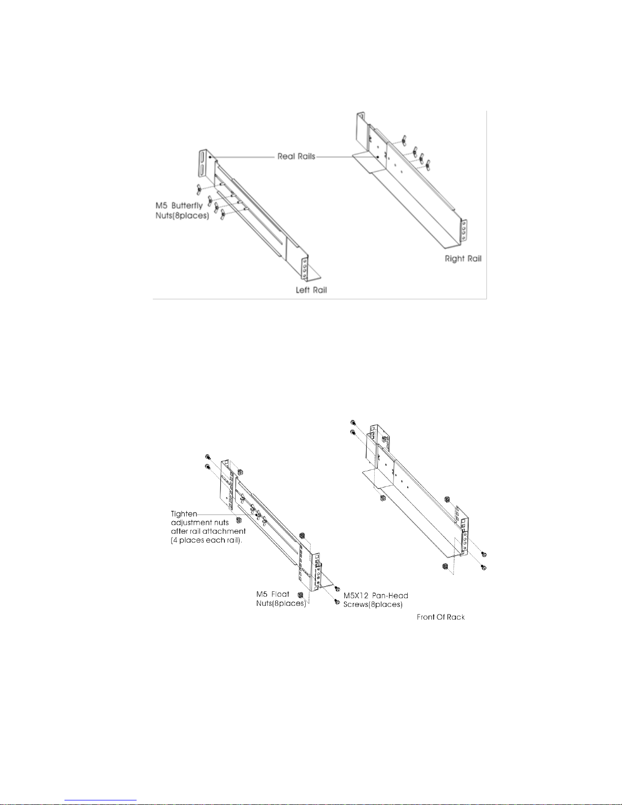
1. Assemble the left and right rails to the rear rails as shown in Figure4.Do not
tighten the screws.
Adjust each rail size for the depth of your rack.
Figure3 Securing the Rails
1. Select the proper size in the rack for positioning the UPS (see Figure 5). The rail
occupies four positions on the front and rear of the rack.
2. Tighten four M5 Umbrella Nuts in the side of rail assembly (see Figure 4).
3. Fix one rail assembly to the front of the rack with one M5×12 pan-head screw
and one M5 cage nut. Using two M5 cage nuts and two M5×12 pan-head screws,
to fix the rail assembly to the rear of the rack.
Figure4 Fixing the Rails
4. Repeat Steps 3 and 4 for the other rail assembly.
5. Tighten the four butterfly nuts in the middle of each rail assembly.
6. If installing optional cabinets, repeat Step 1 through Step 6 for each rail kit.
Page 9
UPServer2.0
ON-LINE DOUBLE CONVERSION
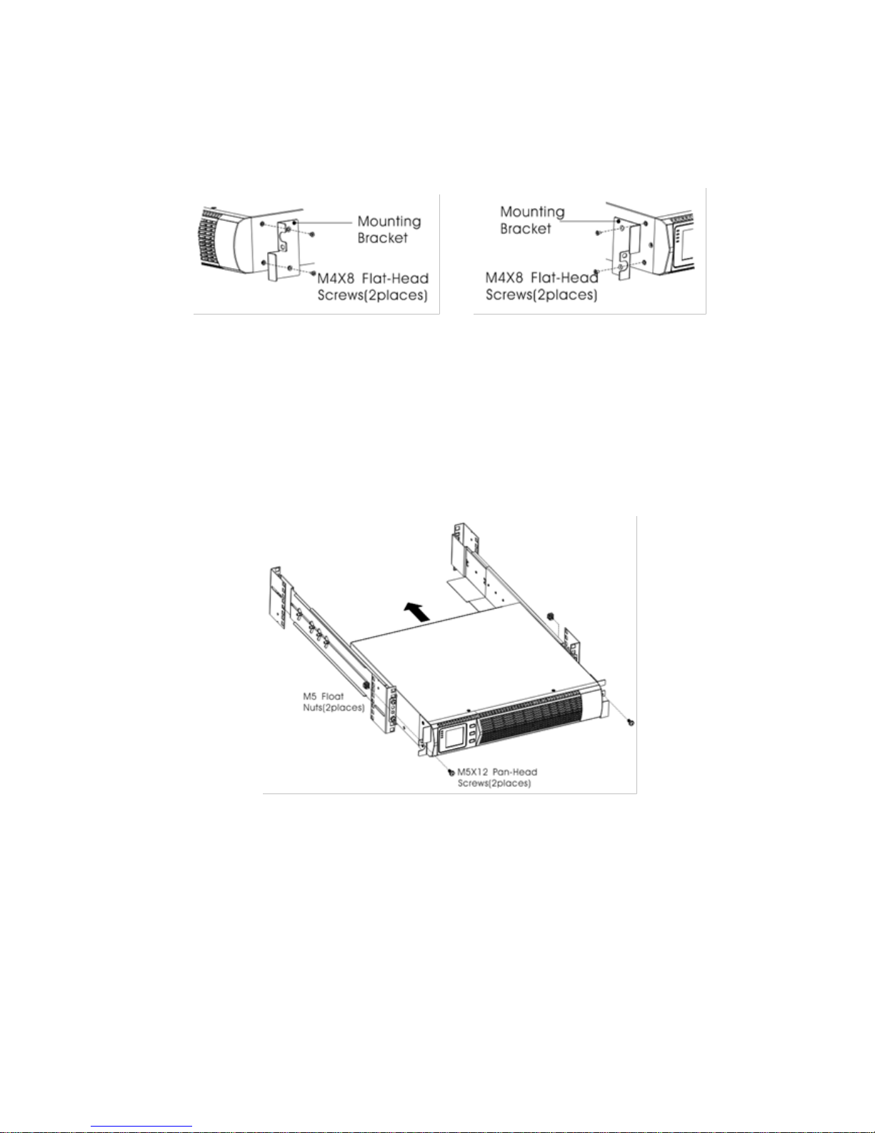
7. Place the UPS on a flat, stable surface with the front of the cabinet facing to
you.
8. Align the mounting brackets with the screw holes on each side of the UPS
and fix with the supplied M4×8 flat-head screws(see Figure 6)
Figure5 Installing the Mounting Brackets
9. If installing optional cabinets, repeat Step 8 and 9 for each cabinet.
10. Slide the UPS and any other optional cabinets into the rack.
11. Secure the front of the UPS to the rack using one M5×12 pan-head screws and
one M5 cage nuts on each side(see Figure 7).Install the bottom screw on each
side through the bottom hole of mounting bracket and the bottom hole of the
rail.
Repeat for any optional cabinets.
Figure6 Securing the Front of the Cabinet
12. Continue to the following section, “Rackmount Wiring Installation.
Page 10
UPServer2.0
ON-LINE DOUBLE CONVERSION
Rackmount Wiring Installation
This section explains:
Installing the UPS, including connecting the UPS internal batteries
Connecting any Optional EBP(S)
Installing the UPS
NOTE
Do not make unauthorized changes to the ups; otherwise, damage may
occur to your equipment and void your warranty.
NOTE
Do not connect the ups power cord to utility until after installation is
completed.
To install the UPS:
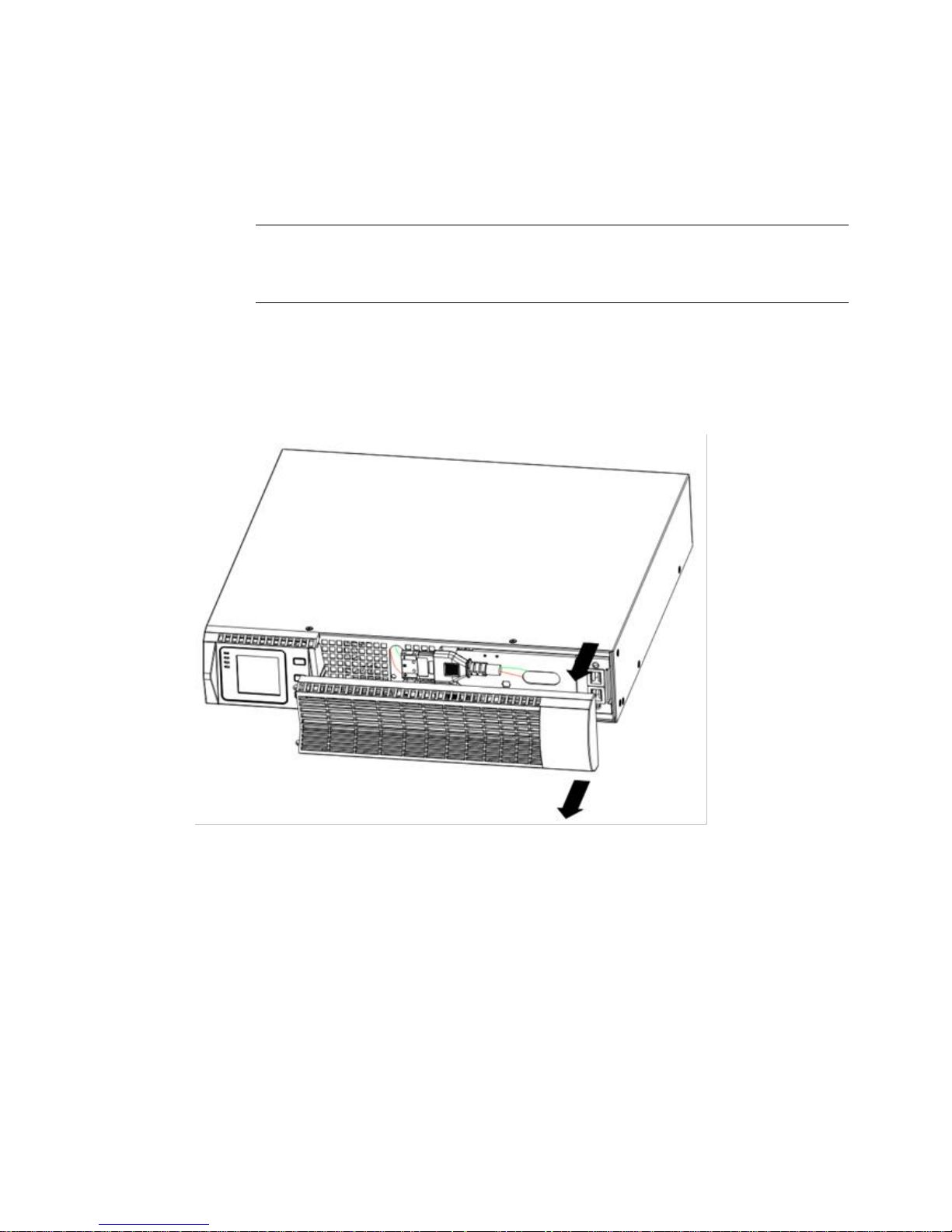
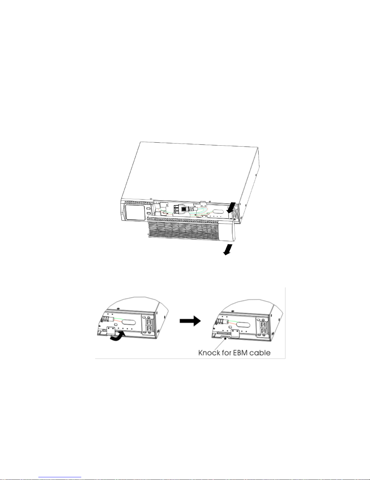
1. Remove the front cover of each UPS
Hold the cover part without LCD on the right side and extract it(see Fig.7)
Figure7 Extract UPS front cover
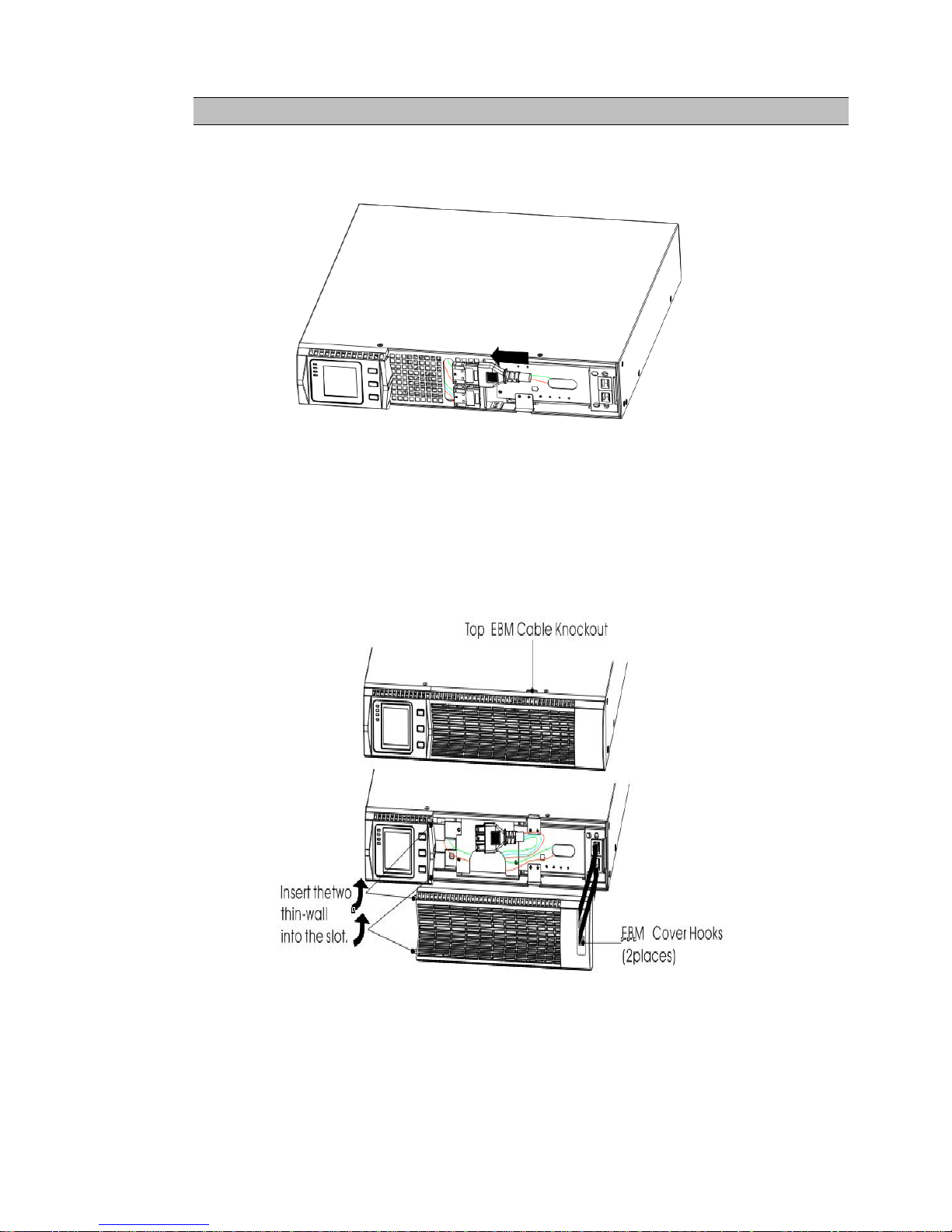
2. Connect the internal battery connector (see Figure8)
Connect red to red, Press the connector tightly together to ensure a proper
connection.
Page 11
UPServer2.0
ON-LINE DOUBLE CONVERSION
CAUTION
A small amount of arcing may occur when connecting the internal batteries. This is
normal and will not harm personnel. Connect the cables quickly and firmly
.
Figure8 Connecting the UPS Internal Batteries
3. If you are installing EBPS, see the following section, “Connecting the EBP(s),” before
continuing with the UPS installation.
4. Replace the UPS front cover.
To replace the cover, verify the EBP cable is routed through the knockout on the bottom of
the cover if EBPS are installed.
Put the front cover hooks of side with display to the cover port, put another side to the
other two ports, then press it until the cover and the chassis are combined tightly.
Figura 9
5. If you are installing power management software, connect your computer to one of the
communication ports or optional connectivity card. For the communication ports, use an
appropriate cable.
6. If your rack has conductors for grounding or bonding of ungrounded metal parts,
Page 12
UPServer2.0
ON-LINE DOUBLE CONVERSION
connect the ground cable (not supplied) to the ground bonding screw. See “Rear Covers”
for the location of the ground bonding screw for each model.
7. If an emergency power-off (disconnect) switch is required by local codes, see “Remote
Emergency Power-off” (REPO) to install the REPO switch before powering on
the UPS.
8. Continue to “UPS Initial Startup”.
Connecting the EBP(s)
To install the optional EBP(s) for a UPS:
1. Remove the front cover of each EBP and UPS (see Figure 11).
It is the same with the installation of the front cover. (Refer” To install the UPS “)
Figure10 Removing the EBP Front Cover
2. On the bottom of the UPS front cover, remove the EBP cable knockout (see Figure 12).
Figure11 Removing the UPS Cable Knockout
3. For the bottom (or only) EBP, remove the EBP cable knockout on the top of the
EBP front cover. See Figure 13 for the location of the top EBP cable knockout.
4. If you are installing more than one EBP, for each additional EBP remove the EBP
cable knockout on the top and bottom of the EBP front cover. See Figure 13 for
the location of the EBP cable knockouts.
Page 13
UPServer2.0
ON-LINE DOUBLE CONVERSION
CAUTION
A small amount of arcing may occur when connecting an EBP to the UPS. This is normal
and will not harm personnel. Insert the EBP cable into the UPS battery connector quickly
and firmly.
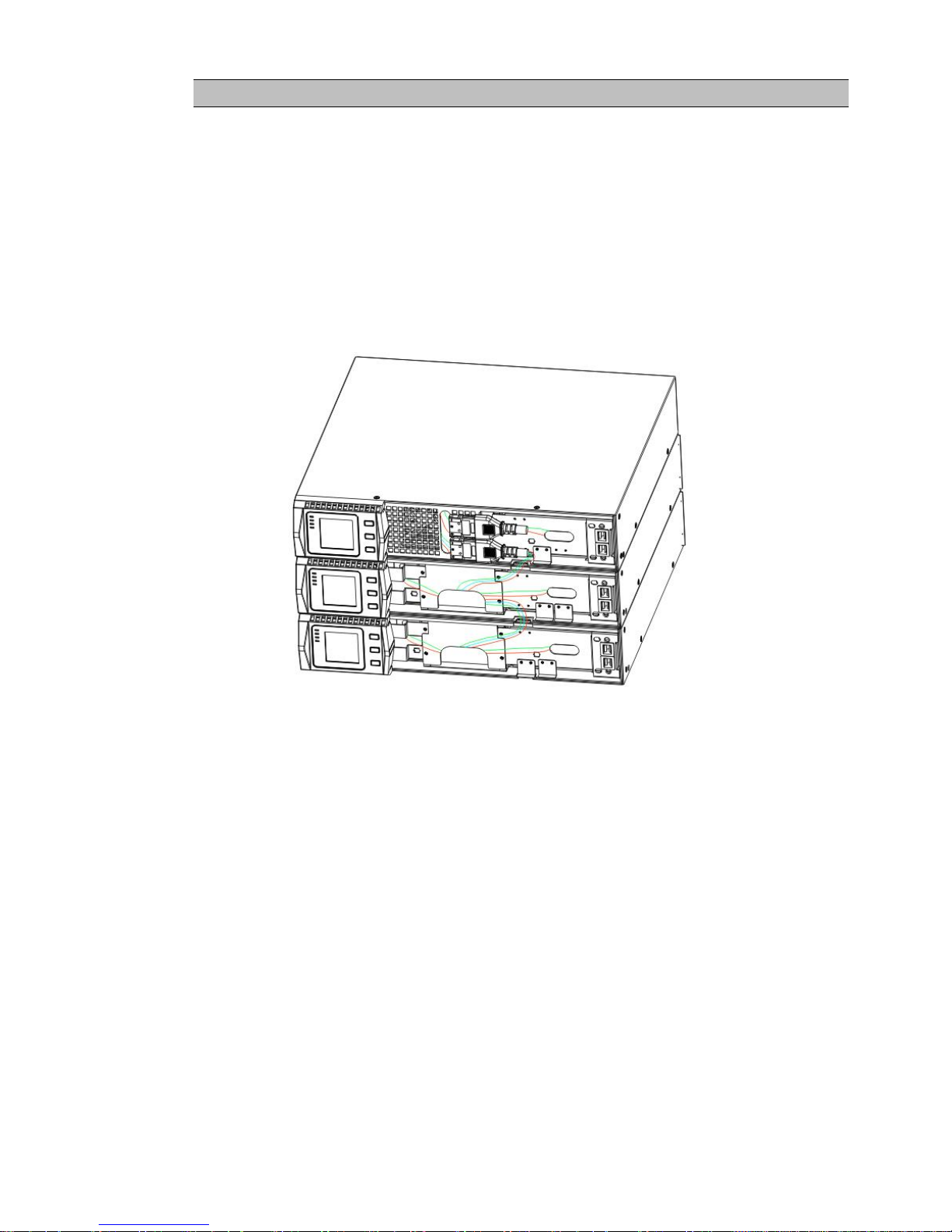
5. Plug the EBP cable(s) into the battery connector(s) as shown in Figure 13. Up to four
EBPS may be connected to the UPS. Connect black to black,. Press the connector tightly
together to ensure a proper connection.
To connect a second EBP, unclip the EBP connector on the first EBP and pull gently to
extend the wiring to the EBP connector on the second EBP. Repeat for any additional
EBPS.
6. Verify that the EBP connections are tight and the adequate bend radius and strain relief
exist for each cable.
Figure12 Typical EBP Installation
7. Replace the EBP front cover.
To replace the cover, verify that the EBP cables are routed through the EBP cover knockouts, cover
connects with the cover hook near the left side of the EBP cabinet. Repeat for each additional EBP.
It is the same with the installation of the front cover. (Refer” to UPS installation”)
8. Verify that all wires connected between the UPS and EBP(s) are installed behind the front covers
and not accessible to users.
9. Return to Step 4 to continue the UPS installation.
Rackmount converted to Tower Installation
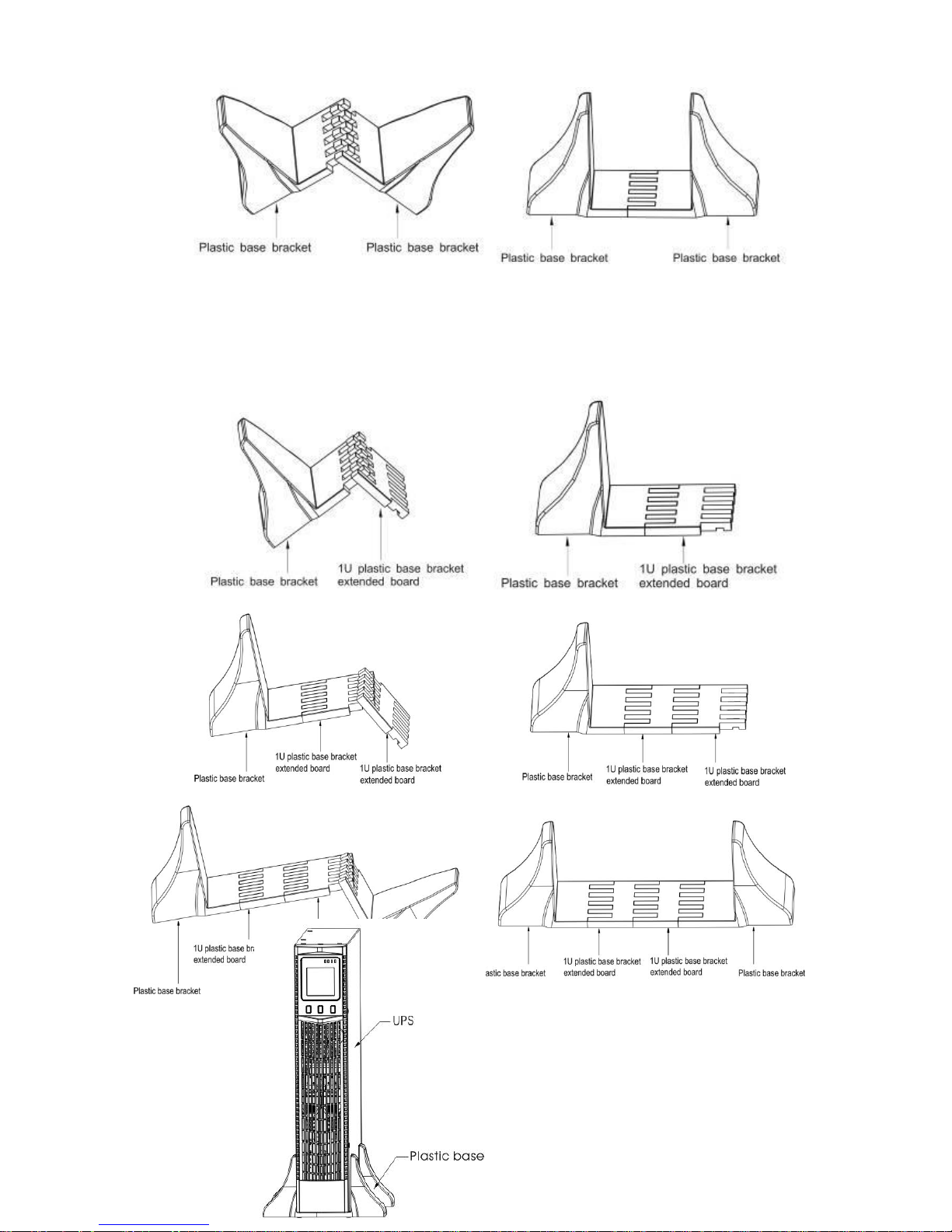
1. Rackmount converted to Tower plastic base installation
① two plastic base brackets ② flatten it after intercrossing
intercross as following Figure
Page 14
UPServer2.0
ON-LINE DOUBLE CONVERSION
Figure 13 plastic base installation
③If an EBP is needed to be placed in the middle, the assembly of plastic base is similar ,
The difference is that two 1U plastic base extended boards are added in the middle.(as the
following shows)
(A) (B)
(C) (D)
(E) (F)
Figure 14 increase EBP plastic base installation
2. The installation between UPS and EBPS can be
referred to Fig.15
Page 15

UPServer2.0
ON-LINE DOUBLE CONVERSION
Figure15 The installation for UPS and battery box
1.Install the base, then place the RT UPS on the base one by one as Fig.16 shows.
2. The cover installation and cable connection of the UPS and EBPS are the same as RT. (To install
the optional EBP(s) for a UPS)
Page 16

UPServer2.0
ON-LINE DOUBLE CONVERSION
UPS initial startup
To start up the UPS:
NOTE Verify that the total equipment ratings do not exceed the UPS capacity to prevent
an
Overload alarm
1. If optional EBPs are installed, verify that the EBPs are connected to the UPS.
2. Plug the equipment to be protected into the UPS, but do not turn on the
protected equipment.
3. Make any necessary provisions for cord retention and strain relief.
4. Plug the detachable UPS power cord into the input connector on the UPS
rear cover.
5. Plug the UPS power cord into a power outlet. The UPS front cover display
illuminates.
6. The UPS will do self-test when power on. After that, the charger will
charge the battery. If the output displayed on LCD is “0”, there is no
output. If you need the UPS output the utility without starting the UPS when
plug into the utility,you need to set bPS option to “ON” on the setting
mode,refer to Page 38.
7. Press the combination start up buttons on the UPS front cover for at least
half a second. The UPS will start up and the LED will turn on and off
sequentially.
8. Check the UPS front cover display for active alarms or notices. Resolve any
active alarms before continuing. See Troubleshooting”. If the indicator
is on, do not proceed until all alarms are clear.Check the UPS status from
the front cover to view the active alarms. Correct the alarms and restart if
necessary.
10. Verify that the indicator illuminates solid, indicating that the UPS is
operating normally and any loads are powered.
11. If optional EBPs are installed, see “Configuring Battery settings” on page
41 to set the number of installed EBPs.
12. To change any other factory-set defaults, see “User settings”
NOTE: At initial startup, the UPS sets system frequency according to input line
frequency (input frequency auto-sensing is enabled by default).
NOTE: At initial startup,please set the output voltage needed before start up the
UPS,After the subsequent startup,the UPS will output the setting voltage.
13. If you installed an optional EPO, test the EPO function: Activate the external
EPO switch. Verify the status change on the UPS display. Deactivate the
external EPO switch and restart the UPS.
NOTE:The internal batteries charge to 80% capacity in less than 5 hours. However,
we recommend that the batteries should be charged for 48 hours after
installation or long-term storage. If optional EBPs are installed, see the
recharge times listed in Table 21.
Page 17
UPServer2.0
ON-LINE DOUBLE CONVERSION
4 OPERATION
This chapter contains information on how to use the UPS, including front cover operation,
operating modes, UPS startup and shutdown, transferring the UPS between modes, and
configuring bypass settings, load segments, and battery settings.
Control Cover Functions
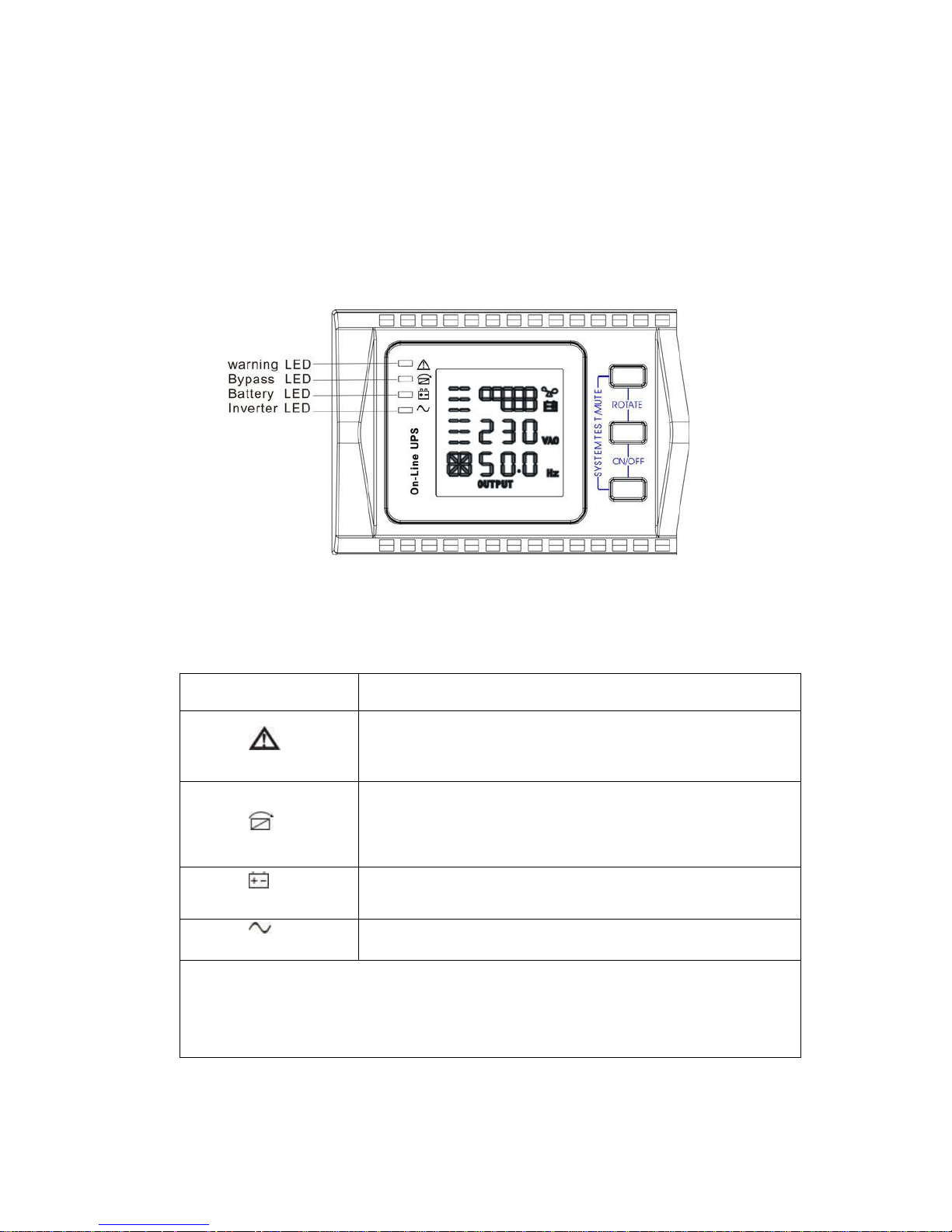
The UPS has a three-button segmental LCD with backlight. It provides useful information about
the UPS itself, load status, measurements, and settings.
Figure16. Control Cover
Table 1. Indicator Descriptions
Indicator
Description
Red
On The UPS has an active alarm or fault.
Yellow
On The UPS is in Bypass mode.
The UPS is operating normally on bypass
during High Efficiency operation.
Yellow
On The UPS is in Battery mode.
Green
On The UPS is operating normally.
NOTE When power on or startup , these indicators will turn on and off
sequentially.
NOTE On different operation modes , these indicators will indicate differently.
Refer to Table 7.
Page 18
UPServer2.0
ON-LINE DOUBLE CONVERSION
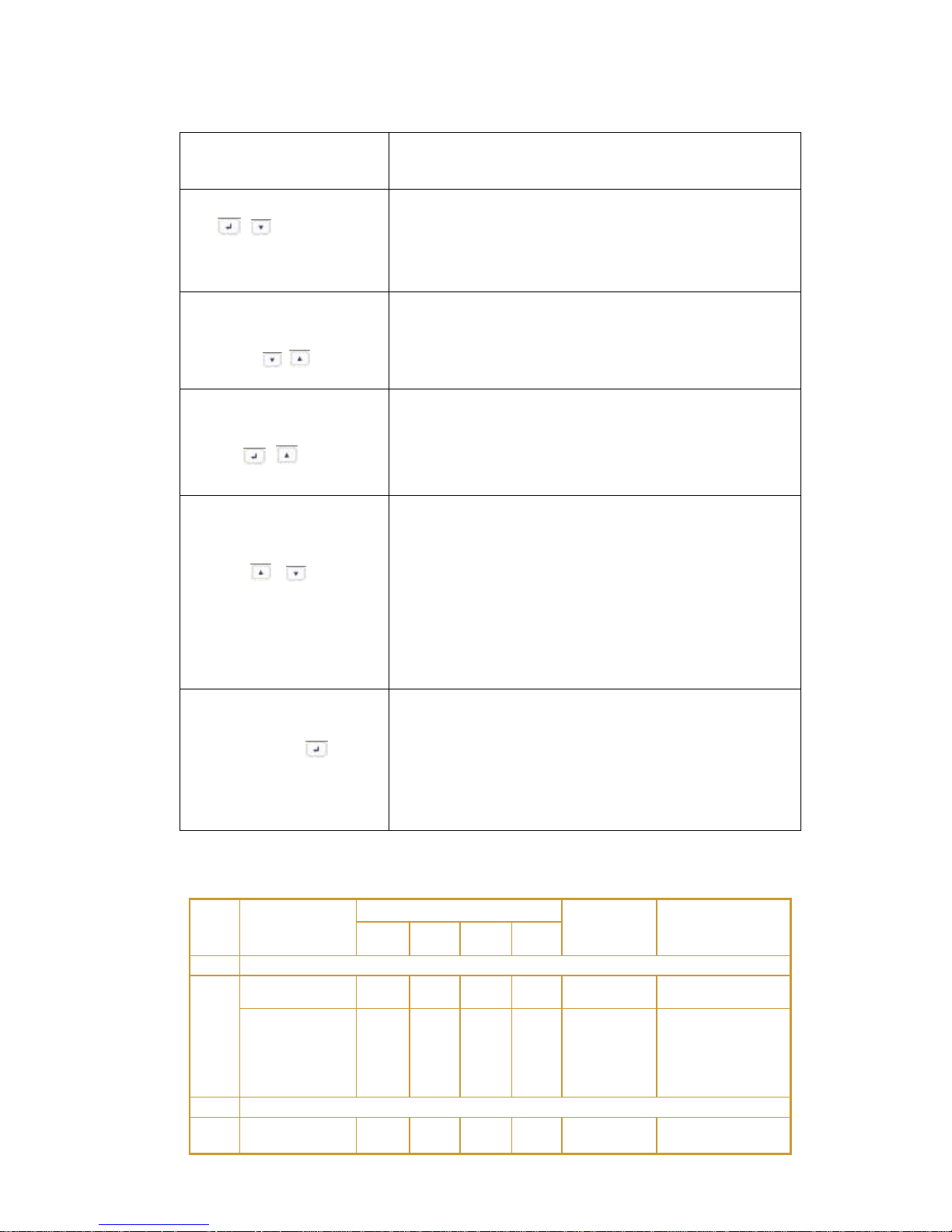
Table 2 . Button function
Button
Function description
Start up combination
( + )
TOWER Press and hold this key for more than half a
second to turn on the UPS.
RT Press and hold this key for more than half a
second to turn on the UPS or to turn off the UPS.
Shutdown/Rotating
combination
( + )
TOWER Press and hold this key for more than half a
second to turn off the UPS.
RT Press and hold this key for more than 2 seconds
to circumrotate the LCD .
Battery test/Mute
combination
( + )
Press and hold the key for more than 1 second in Line
mode or economic(ECO) mode: UPS runs self-test
function.
Press and hold the key for more than 1 second in
battery mode: UPS runs mute function.
Scroll or
Non-function setting mode:
Press and hold the key for more than half a second
(less than 2 seconds): Indicate the items of the LCD
item section orderly.
Press and hold this key for more than 2 seconds:
Circularly and orderly display the items every 2
seconds, when press and hold the key for some time
again, it will turn to output status.
Function setting mode:
Press and hold the key for more than half a second
(less than 2 seconds): Select the set option.
Setting entry
Non-function setting mode:
Press and hold the key for more than 2 seconds:
Function setting interface.
Function setting mode:
Press and hold the key for more than half a second
(less than 2 seconds): Affirm the set option.
Press and hold the key for more than 2 seconds, exit
from this function setting interface.
Table 3. The corresponding working status of indications
NO
Working
status
Indication
Warning
Remarks
Nor
Bat
Bps
Fau
1
Line mode
Normal
●
None
High/low
voltage
protection,
turn to
battery mode
● ●
★
Once
every four
seconds
2
Battery mode
Normal
voltage
● ●
★
Once
every four
Page 19

UPServer2.0
ON-LINE DOUBLE CONVERSION
seconds
Battery
Voltage
abnormal
warning
●
★
★
Once per
second
3
Bypass mode
Main AC
Normal
voltage in
bypass mode
● ★
Once
every two
minutes
Eliminate after
starting the UPS
Main AC high
voltage
warning in
bypass mode
★
Once
every four
seconds
Main AC low
voltage
warning in
bypass mode
★
Once
every four
seconds
4
Battery disconnect warning
Bypass mode
● ★
Once
every four
seconds
Affirm if the
battery switch is
closed
Inverting
mode inverting
mode
●
★
Once
every four
seconds
Affirm if the
battery switch is
closed
Power up or
start
Six times
Affirm if the
battery is
connected well
5
Output overload protection
Overload
warning in
line mode,
●
★
Twice per
second
Remove the
uncritical loads
Overload in
line mode,
protection
● ●
Long
beeps
Remove the
uncritical loads
Overload
warning in
battery mode
● ●
★
Twice per
second
Remove the
uncritical loads
Overload in
battery
mode,
protection
● ●
●
Long
beeps
Remove the
uncritical loads
6
Overload
warning in
bypass mode
● ★
Once
every 2
seconds
Remove the
uncritical loads
7
Fan fault (fan
icon flashing)
▲ ▲ ▲
★
Once
every 2
seconds
Check if the fan
is blocked by
object.
8
Fault mode
●
Long
beeps
If display fault
code and
icon lights,
contact for
maintenance
when you
can’t deal with
it by yourself.
● _indicator lights for a long time
Page 20
UPServer2.0
ON-LINE DOUBLE CONVERSION
★ _indicator flashes
▲ _the status of indicator depends on other conditions
Display Functions
As the default or after 5 minutes of inactivity, the LCD displays the
output parameters.
The backlit LCD automatically dims after 5 minutes of inactivity. Press
any button to restore the screen.
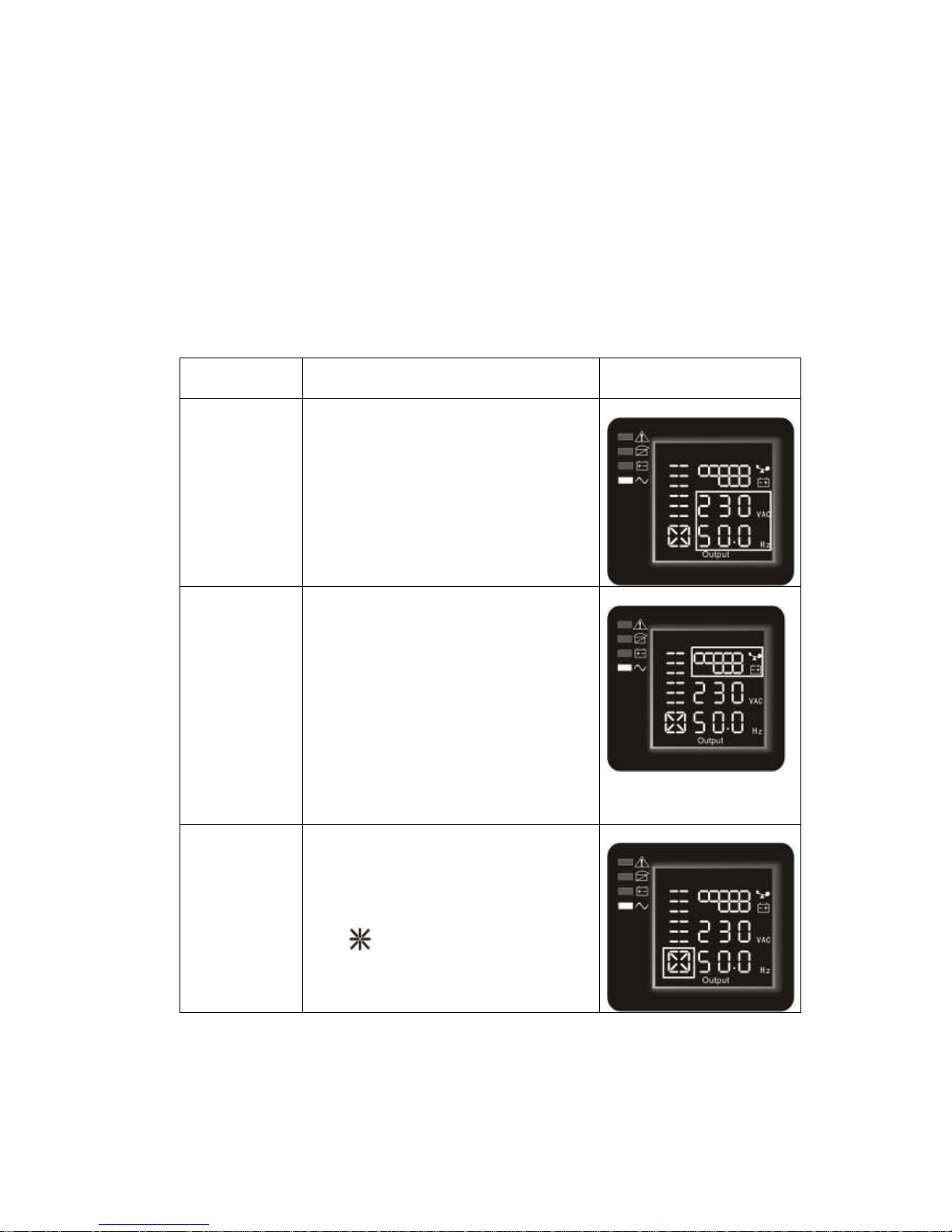
LCD display comprises numerical value section, capacity graphics section, fan-status graphics
section and charger-status graphics section , refer to Table 4 for detail.
Table 4. LCD display section
Section
Description
Graphic
Numerical
value
section
Display the corresponding numerical
value of inquiring items(output, load,
temperature, input, battery), for
example, as the graphics shows above,
the output voltage is 230v, the output
frequency is 50Hz.
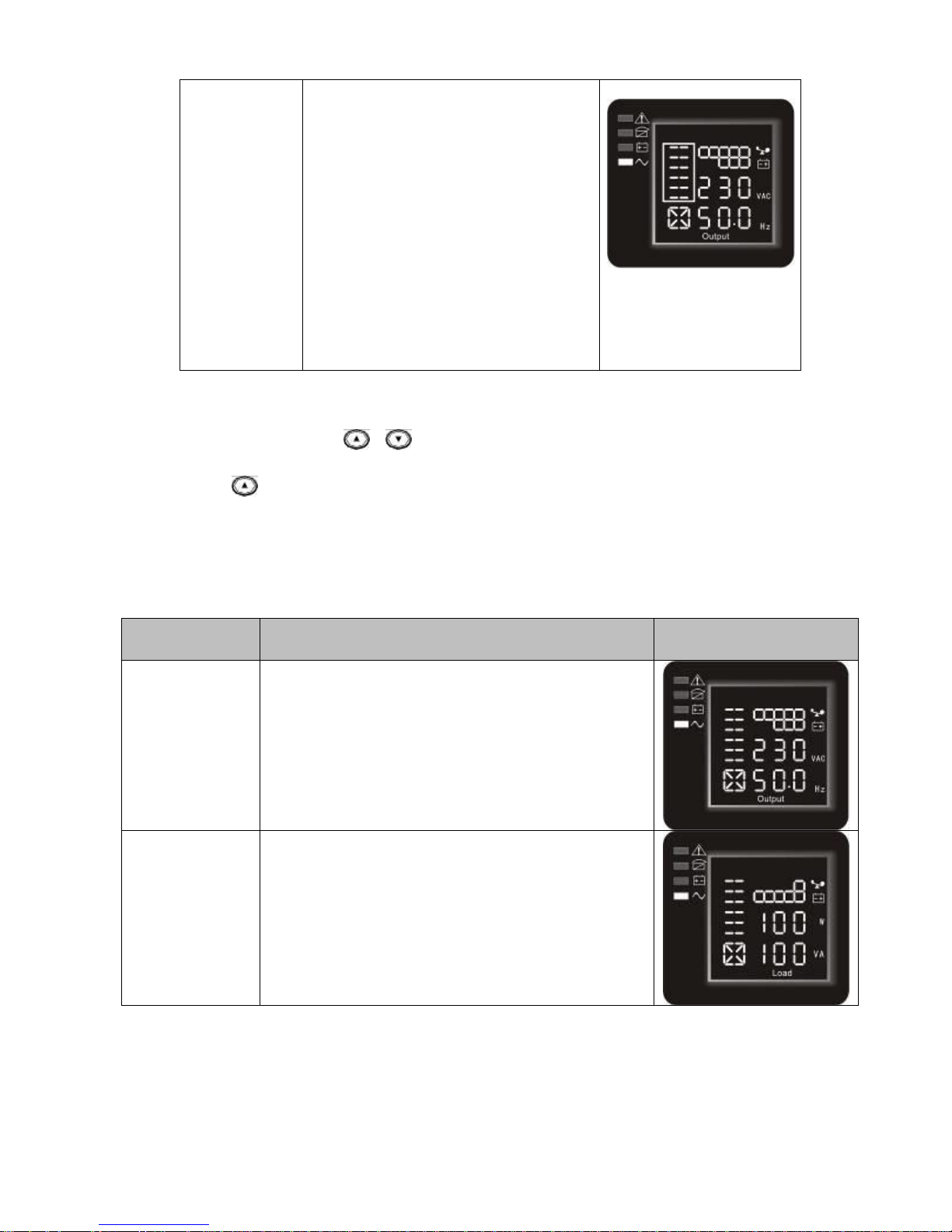
Capacity
graphics
section
Display the capacity of the battery and
load. Every pane represents 20 %
capacity. As graphics shown above,
the capacity of the battery is 80 %
-100% ( 5 panes), the load reaches
40 % -60 % (3 panes). When UPS is
overloaded, the icon will flash, when
battery is weak or disconnected, the
icon will also flash.
Fan-status
graphics
section
Display if the fan works normally.
When the fan works normally, it will
show the dynamic fan blades rotating;
when the fan works abnormally, the
icon will keep on flashing with the
warning .
Page 21
UPServer2.0
ON-LINE DOUBLE CONVERSION
Charger-status
graphics
section
Display the status of the charger.
When charger works normally, the
corresponding icon will vary
dynamically and orderly.
when charger works abnormally, the
icon will keep flashing
When UPS is in battery mode, the
number of the icons of the
charger-state section will vary
according to the changeable capacity
of the battery (pane).
Parameters inquiring
Press and hold the scroll key or for more than half a second(less than 2 seconds) to inquire
about items. The inquired items include input, battery, output, load, temperature.。Press and hold
the scroll key for more than 2 seconds, LCD begins to display the items circularly and orderly
which transfer to another every 2 seconds. Press and hold the key for some time again, it will
return to output status.
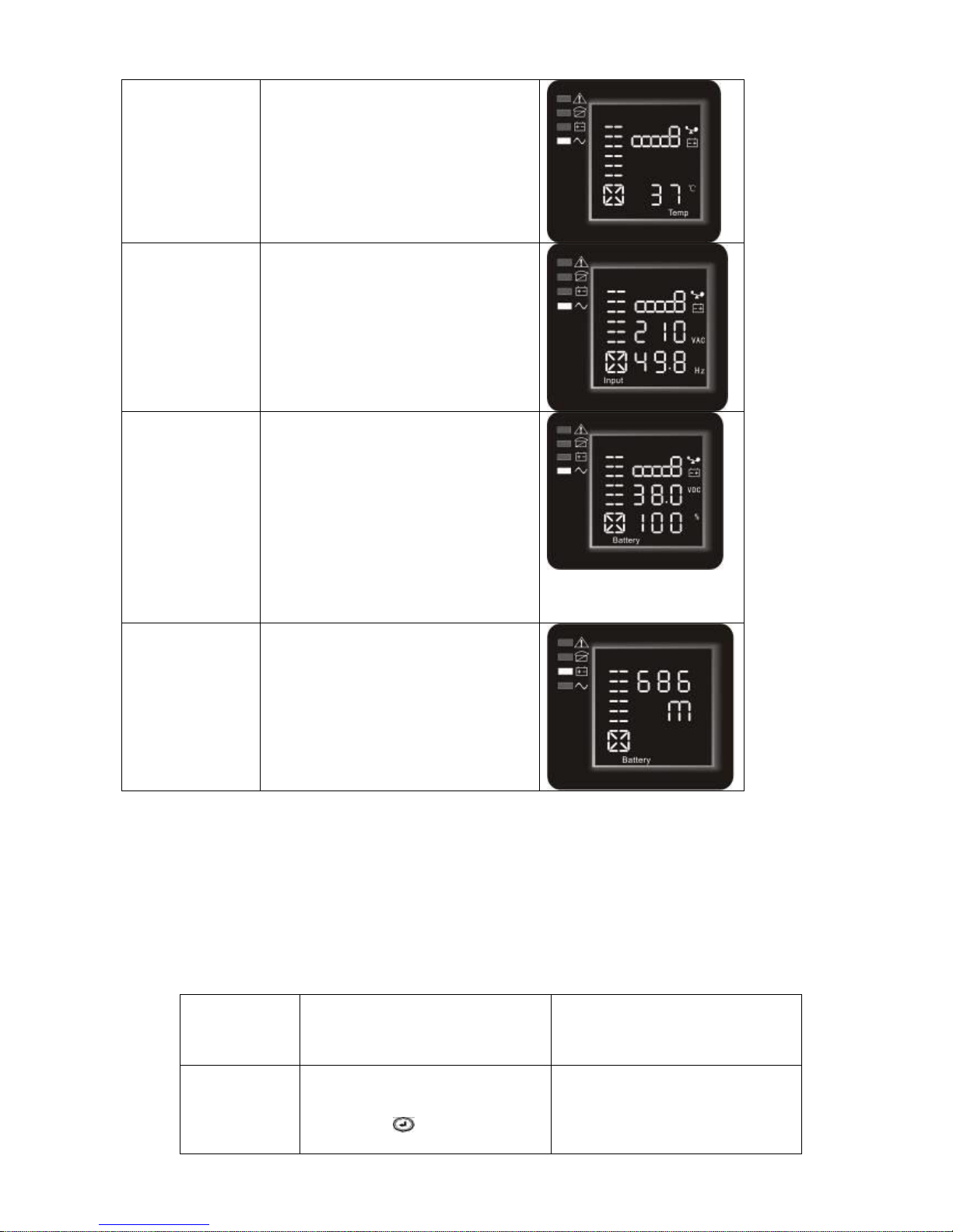
Tabella 5. Visualizzazione misure
MISURA
DESCRIZIONE
GRAFICA DISPLAY
Uscita
Il display visualizza la tensione e la frequenza in uscita
UPS. Dal grafico a lato si vede una tensione di 230V ed
una frequenza di 50,0Hz.
Carico
Il display visualizza la potenza attiva (W) e la potenza
apparente (VA) del carico. Dal grafico a lato si vede che il
carico assorbe una potenza 100W e 100VA. Senza carico
è possibile che vengano visualizzati piccoli valori.
Page 22
UPServer2.0
ON-LINE DOUBLE CONVERSION
Temperature
Display the temperature of the
inverter in the UPS. As the
following graphics shown: the
temperature of the inverter is 37℃.
Input
Display the voltage and frequency
of the input. As the following
graphics shown: the input voltage is
210v, input frequency is 49.8Hz.
Battery
Display the voltage and capacity of
the battery . As the following
graphics shown: the battery voltage
is 38v, the capacity of battery is
100 % (the capacity of battery is
approximately reckoned according
to the battery voltage).
Battery
remaining time
Display the battery remaining time
when under battery mode. The
number is from 0 to 999 minutes. As
the following graphics shown: there
are 686 minutes left for discharging.
User Settings
The UPS has setting functions. This user settings can be done under any kind of UPS working
mode. The setting will take effect under certain condition. Below table describes how to set the
UPS.
Table 6. User Settings
Setting
function(serial
number)
Setting procedure
LCD display
① Enter the setting interface.
Press and hold the function
setting key for more than 2
seconds, then come to setting
Page 23
UPServer2.0
ON-LINE DOUBLE CONVERSION
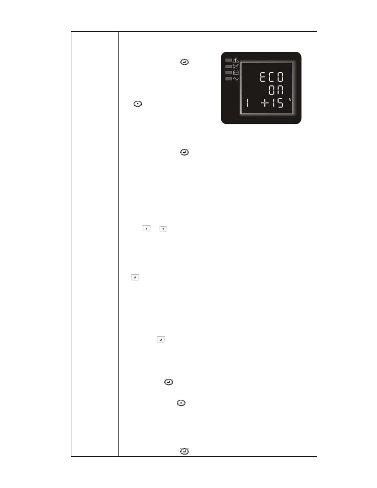
ECO function
setting(1)
interface, the letters “ECO”
will flash.
② Enter the ECO setting
interface. Press and hold the
function setting key for more
than half a second(less than 2
seconds), the letters “ECO”
will stop flash. The “ON”(or
OFF) below the ECO will flash.
Press and hold the scroll
key for more than half a
second (less than 2 seconds) to
determine whether the ECO
function is enabled or disabled.
③ Confirm the ECO selecting
interface. After selecting ON or
OFF, press and hold the
function setting key for more
than half a second (less than 2
seconds). Now, the ECO setting
function is completed and the
“ON” or “OFF” below the
“ECO” will light without flash.
④ If you choose “OFF”, then
go to step 7, otherwise go
ahead to step 5.
⑤ Set the ECO tolerance range.
Short press the scroll
key or for more than
half a second (shorter than 2
seconds)to select the
voltage range in percentage.
+5%,+10%,+15%,+25%(def
ault is +25%) , then short
press function setting key
for more than half a
second (shorter than 2
seconds)to confirm the
selection, then to set the
minus range
⑥ To set the minus range in the
same way.
⑦ After the minus range is
confirmed. Long press function
setting key for more than 2
seconds to exit setting menu.
Bypass
function
setting(2)
① Enter the setting interface.
Press and hold the function
setting key for more than
2 seconds, then come to
setting interface ,short press
the scroll key for more
than half a second (less than
2 seconds) to select BPS
setting, the letters “bPS”
will flash.
② Enter the BPS setting
interface. Press and hold the
function setting key for more
Page 24
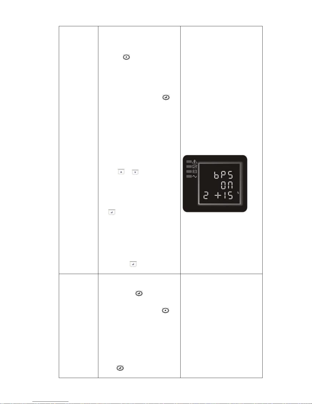
UPServer2.0
ON-LINE DOUBLE CONVERSION
than half a second(less than 2
seconds) at this time, the letters
“bPS” will stop flashing. The
“ON”(or OFF) below the bPS
will flash. Press and hold the
scroll key for more than half a
second (less than 2 seconds) to
determine whether the BPS
function is enabled or disabled.
③ Confirm the BPS selecting
interface. After selecting ON
or OFF, press and hold the
function setting key for
more than half a second
(less than 2 seconds). Now,
the BPS setting function is
completed and the “ON”
or “OFF” below the
“bPS” will light without
flashing.
④ If you choose “OFF”, then
go to step 7, otherwise go
ahead to step 5.
⑤ Set the BPS tolerance range.
Short press the scroll
key or for more than
half a second (shorter than 2
seconds)to select the
voltage range in percentage.
+5%,+10%,+15%,+25%(def
ault is +25%) , then short
press function setting key
for more than half a
second (shorter than 2
seconds)to confirm the
selection, then to set the
minus range
⑥ To set the minus range in the
same way.
⑦ After the minus range is
confirmed. Long press function
setting key for more than 2
seconds to exit setting menu.
Output
voltage
setting(3)
① Enter the setting interface.
Press and hold the function
setting key for more than
2 seconds, then come to
setting interface, Press and
hold the scroll key for
more than half a second(less
than 2 seconds), select the
function setting, choose
output voltage setting
interface, at the moment, the
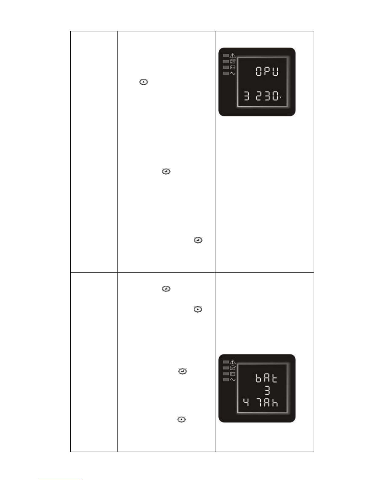
letters “OPU” will flash.
② Enter the output voltage
selecting interface. Press and
hold the function setting
key for more than half a
second(less than 2 seconds),
Page 25
UPServer2.0
ON-LINE DOUBLE CONVERSION
then come to setting
interface of output voltage
OPU, at this time, the letters
“OPU” will light for a long
time. The numerical value
below the OPU will flash.
Press and hold the scroll
key for more than half a
second (less than 2 seconds),
select the numerical value in
accordance with “OPU”
function. The provided
voltages are 208v, 220v,
230v, 240,you can choose
any one of them by yourself
(The default is 220v).
③ Confirm the output voltage
selecting interface. After
selecting numerical value,
press and hold the function
setting key for more than
half a second (less than 2
seconds). Now, the OPU
setting function is
completed and the
numerical value below the
“OPU” will light without
flashing.
④ Exit from the setting
interface. Press and hold
function setting key for
more than half a second (less
than 2 seconds), exit from
the setting interface and
return to main interface.
Battery string
number and
type
setting(4)
① Enter the setting interface.
Press and hold the function
setting key for more than
2 seconds, then come to
setting interface, Press and
hold the scroll key for
more than half a second(less
than 2 seconds), select the
function setting, choose
battery setting interface, at
the moment, the letters
“bAt” will flash.
② Enter the battery setting
interface. Press and hold the
function setting key for more
than half a second(less than 2
seconds), then come to setting
interface of battery, the letters
“bAt” will stop flashing. The
numerical value below the
“bAt” will flash. Press and
hold the scroll key for more
than half a second (less than 2
seconds), select the numerical
value in accordance with the
real connected battery strings.
Page 26
UPServer2.0
ON-LINE DOUBLE CONVERSION
③.Confirm the battery strings
setting interface。
After selecting numerical value,
press and hold the function
setting key for more than half
a second (less than 2 seconds).
Now, the battery strings setting
is confirmed and the battery
type value below will flash。
④ set the battery type in the
same way.
⑤Exit from the setting interface.
Press and hold function setting
key for more than half a
second (less than 2 seconds),
exit from the setting interface
and return to main interface.
Load segment
setting(5)
① Enter the setting interface.
Press and hold the function
setting key for more than 2
seconds, then come to setting
interface, Press and hold the
scroll key for more than half a
second(less than 2 seconds),
select the function setting,
choose battery setting
interface, at the moment, the
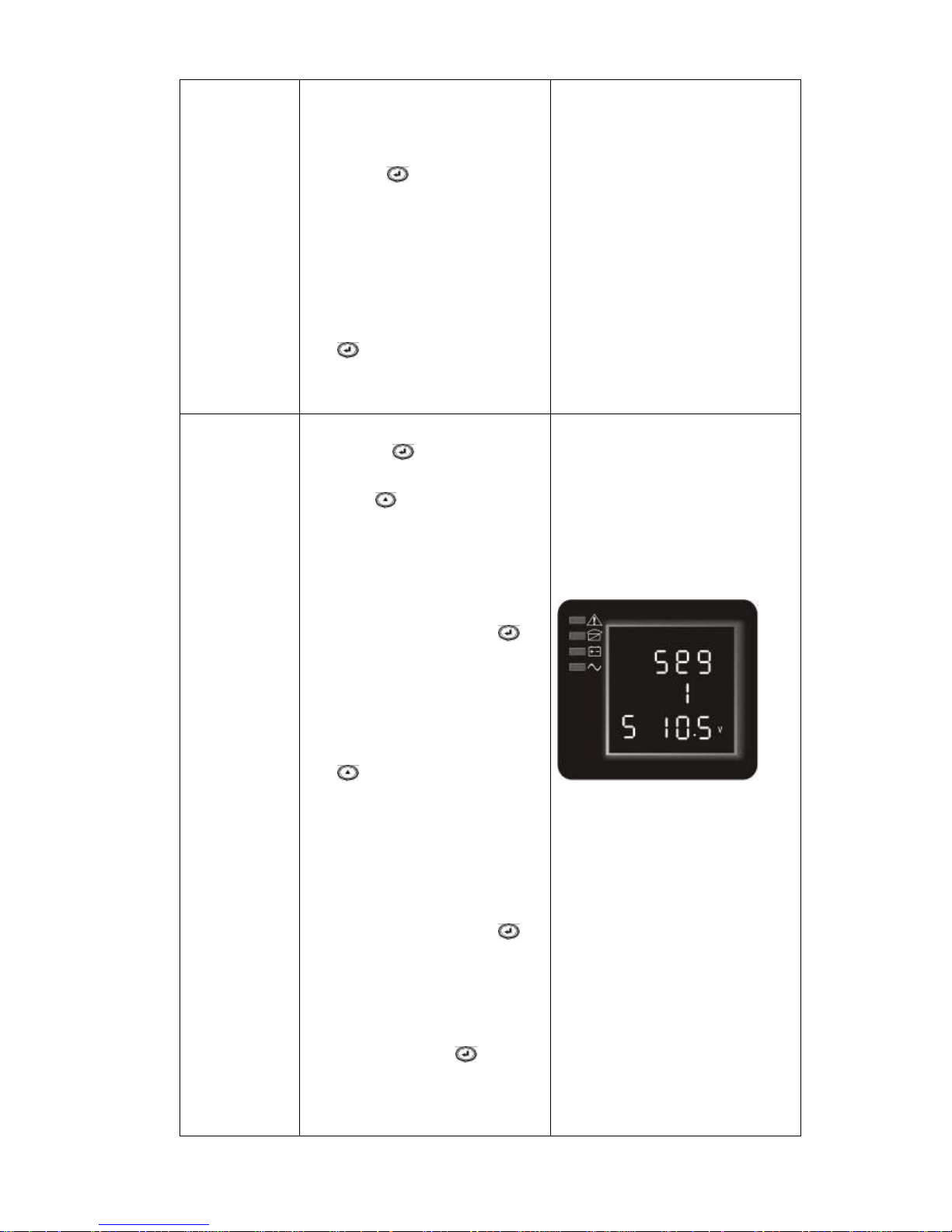
letters “Seg 1” will flash.
② Enter the load segment
setting interface. Press and hold
the function setting key for
more than half a second(less
than 2 seconds), then come to
setting interface of load
segment, the letters “Seg 1”
will stop flashing. The numerical
value below the “Seg 1” will
flash. Press and hold the scroll
key for more than half a
second (less than 2 seconds),
select the battery voltage,
10.5v, 11.0v ,11.5v(default is
10.5v)。
③Confirm the power shedding
shielding battery voltage
setting. After selecting
numerical value, press and hold
the function setting key for
more than half a second (less
than 2 seconds). Now, the load
shielding battery voltage
setting is confirmed.
④ Exit from the setting
interface. Press and hold
function setting key for more
than half a second (less than 2
seconds), exit from the setting
interface and return to main
interface.
Page 27
UPServer2.0
ON-LINE DOUBLE CONVERSION
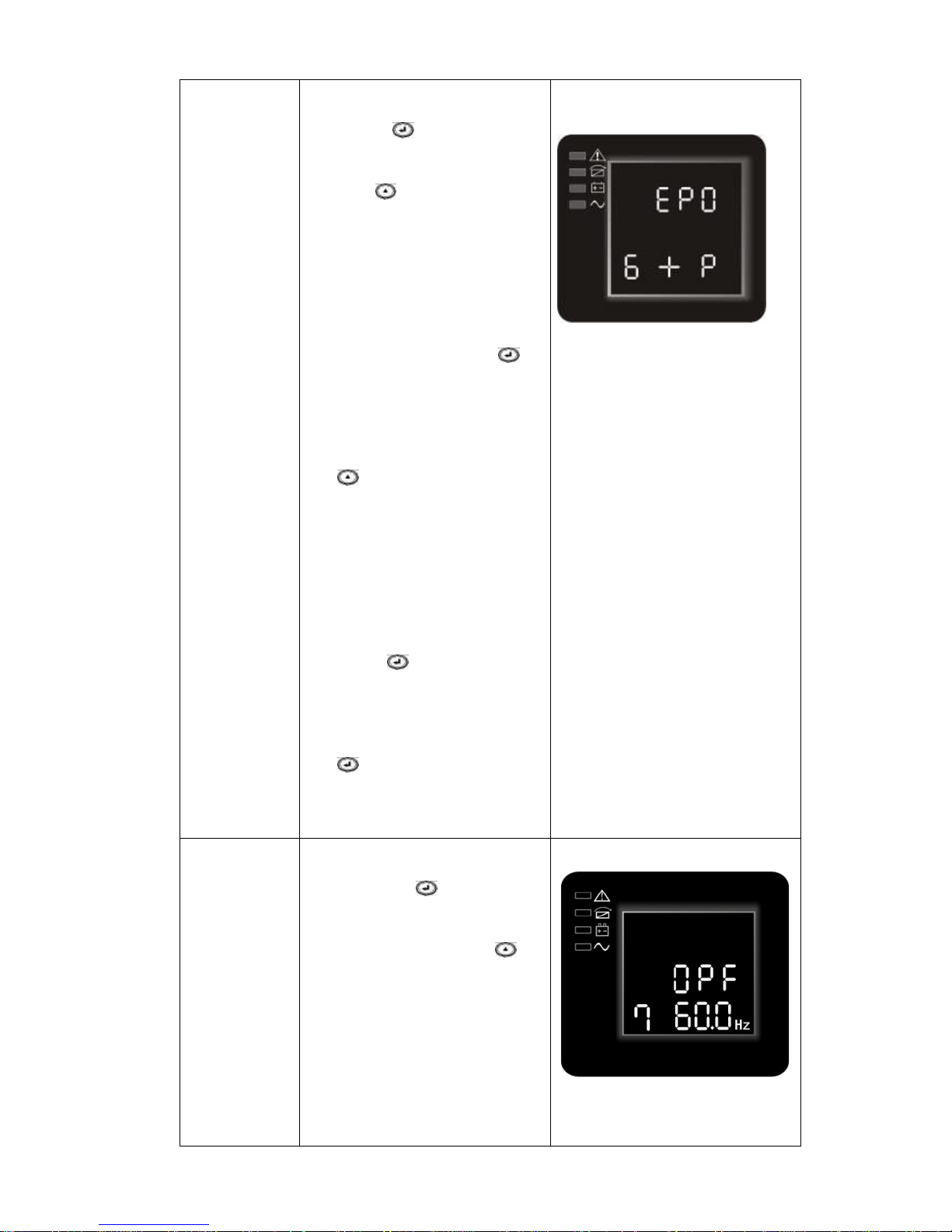
EPO Input
Polarity
setting(6)
① Enter the setting interface.
Press and hold the function
setting key for more than 2
seconds, then come to setting
interface, Press and hold the
scroll key for more than half a
second(less than 2 seconds),
select the function setting,
choose EPO Input polarity
setting interface, the letters
“EPO” will flash.
②Enter the EPO Input Polarity
setting interface. Press and hold
the function setting key for
more than half a second(less
than 2 seconds) , the letters
“EPO” will stop flashing. The
letters below the “EPO” will
flash. Press and hold the scroll
key for more than half a
second (less than 2 seconds),
select the EPO input polarity,
“+P”(open circuit execute
EPO function) or “–P”(short
circuit execute EPO function)
③ Confirm the setting. After
selecting EPO input polarity,
press and hold the function
setting key for more than half
a second (less than 2 seconds).
Now, the setting is confirmed.
④Exit from the setting interface.
Press and hold function setting
key for more than half a
second (less than 2 seconds),
exit from the setting interface
and return to main interface.
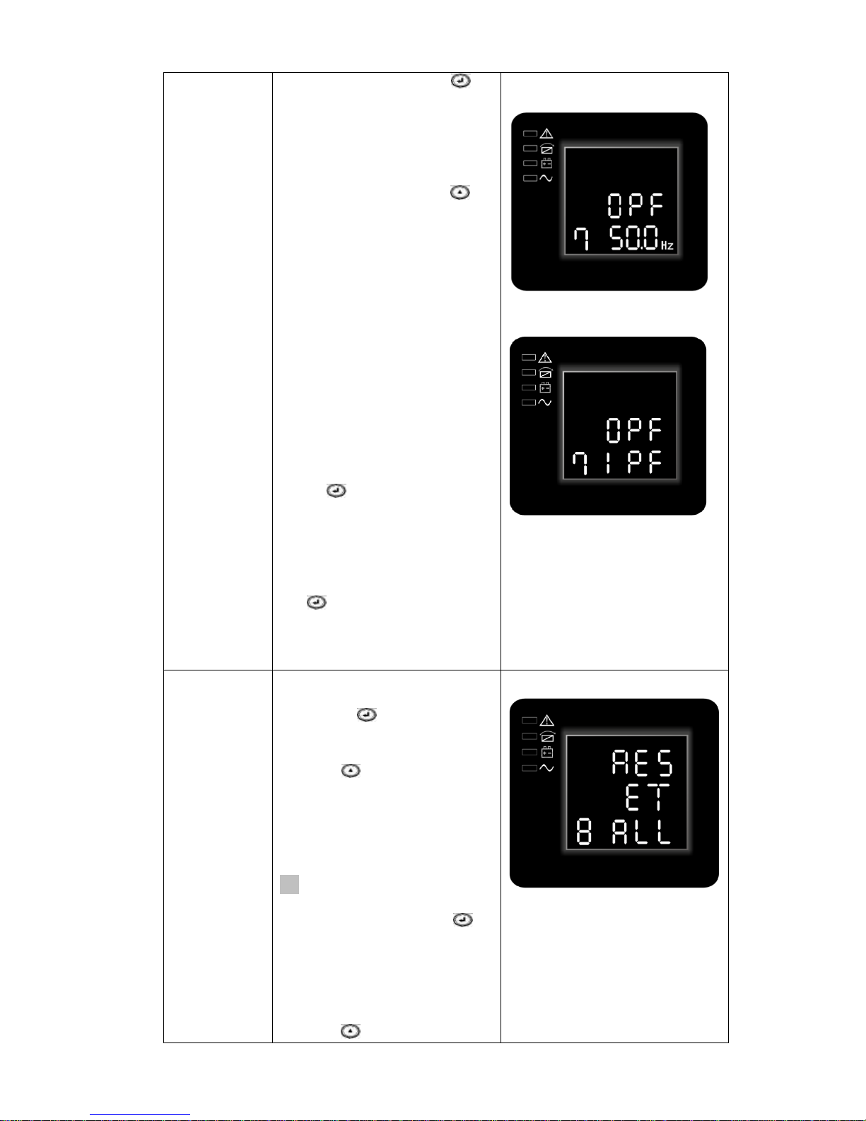
Frequency
Converter
mode setting
(7)
① Enter the setting interface.
Press and hold the function
setting key for more than
2 seconds, then come to
setting interface, Press and
hold the scroll key for
more than half a second(less
than 2 seconds), select the
function setting, choose
output frequency setting
interface, the letters
“OPF” will flash.
② Enter the output frequency
of converter mode setting
interface. Press and hold the
Page 28
UPServer2.0
ON-LINE DOUBLE CONVERSION
function setting key for
more than half a second(less
than 2 seconds) , the letters
“OPF” will stop flashing.
The letters below the
“OPF” will flash. Press and
hold the scroll key for
more than half a second
(less than 2 seconds), select
the output frequency,
“50Hz”(output fixed to
50Hz and active converter
mode) or “60Hz”(output
fixed to 60Hz and active
converter mode) or
“IPF”(inactive converter
mode and active normal
mode)
③ Confirm the setting. After
selecting converter mode
output frequency, press and
hold the function setting
key for more than half a
second (less than 2
seconds). Now, the setting is
confirmed.
④Exit from the setting interface.
Press and hold function setting
key for more than half a
second (less than 2 seconds),
exit from the setting interface
and return to main interface.
Parameter
reset to
factory
Setting(8)
① Enter the setting interface.
Press and hold the function
setting key for more than 2
seconds, then come to setting
interface, Press and hold the
scroll key for more than half a
second(less than 2 seconds),
select the function setting,
choose parameter reset setting
interface, the letters “RESET”
will flash.
② Enter the parameter reset
setting interface. Press and hold
the function setting key for
more than half a second(less
than 2 seconds) , the letters
“RESET” will stop flashing.
The letters below the “RESET”
will flash. Press and hold the
scroll key for more than half a
Page 29
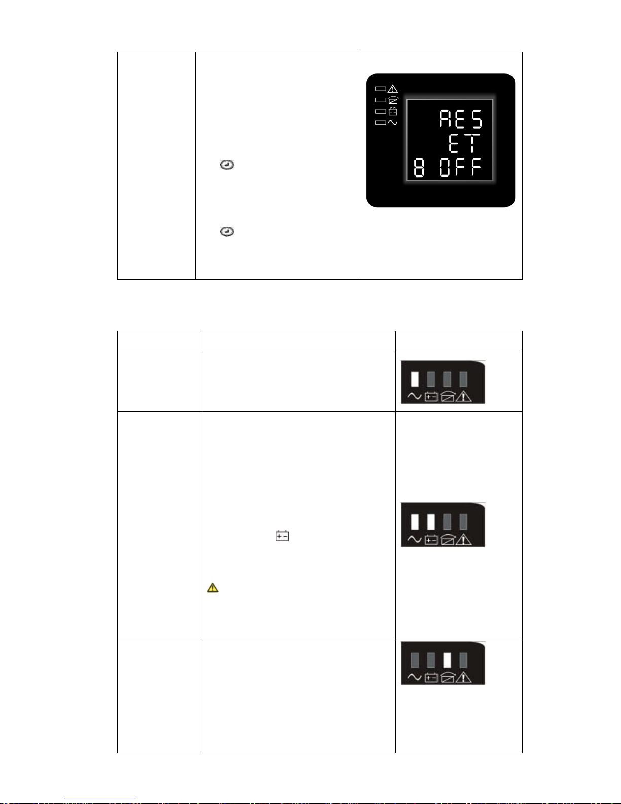
UPServer2.0
ON-LINE DOUBLE CONVERSION
second (less than 2 seconds),
select “ALL”(setting
parameter reset to factory
setting) or “OFF”(not do reset
and do nothing).
③ Confirm the setting. After
selecting the option, press and
hold the function setting
key for more than half a
second (less than 2 seconds).
Now, the setting is confirmed.
④Exit from the setting interface.
Press and hold function setting
key for more than half a
second (less than 2 seconds),
exit from the setting interface
and return to main interface.
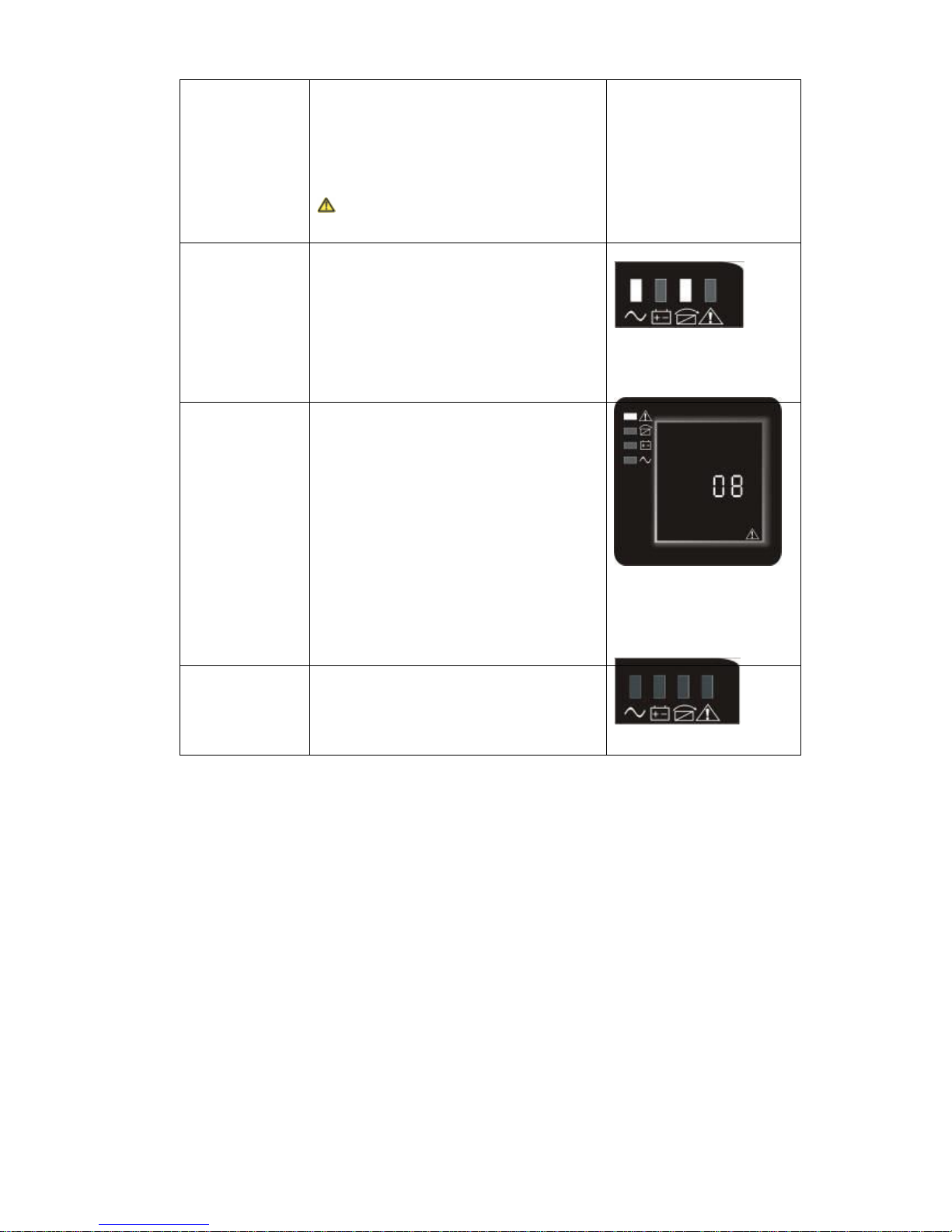
Table 7. Operating Modes
Mode
Description
Indicator
Line Mode
The inverter green LED is on.
When input AC mains is in line with
the working conditions, UPS will work
in line mode,charge the battery and
protect the load.
Battery
Mode
Both the inverter green LED and
battery yellow LED are on, the buzzer
beeps once every 4 seconds. The
warning red LED is on when beeping.
When the mains power down or
instable, UPS will turn to battery mode
at once. If the mains recovers,the UPS
will transfer to line mode.
If battery low alarm activates, the
indicator of flashes. If battery
voltage reaches low limit, UPS will turn
off to protect the battery. UPS will
auto-restart when the mains recover.
NOTE:The back up time of battery
mode is subject to the load and EBP
numbers. Battery remaining time
displayed on the LCD may not be
accurate.
Bypass Mode
Bypass yellow LED is on, the buzzer
beeps once every 2 minutes . The
warning red LED is on when beeping,
LCD displays are according to the
exact load and battery capacity.
Bypass tolerance can be set by LCD.
Under below conditions, the UPS will
transfer to bypass mode:
● BPS on set by user through LCD,
Page 30
UPServer2.0
ON-LINE DOUBLE CONVERSION
and the UPS is turned off.
● BPS on set by user through LCD,
and the UPS is plugged into utility but
not turned on.
● Overload on line mode or ECO
mode.
NOTE:When in bypass mode , the
load is not protected.
ECO Mode
Both the inverter green LED and
bypass yellow LED are on.
When ECO enabled and the utility is in
range, the UPS will work on ECO
mode. If the utility in out of ECO range
but still in Line range, the UPS will
transfer to line mode.
Utility tolerance of ECO mode can be
set。
Fault Mode
When the UPS has fault. The warning
red LED is on and the buzzer beeps.
The UPS will turn to fault mode. The
UPS cuts off the output and the LCD
display fault codes. At the moment,
you can press the mute key to make
the buzzer stop beeping temporarily
to wait for maintenance. You can also
press the OFF key to shut down the
UPS when confirm that there is no
serious fault.
NOTE: As for corresponding
information of the fault code, please
refer to Table 23 Fault Code.
Standby
Mode
When UPS is plugged into line and not
turn on , the UPS will work in standby
mode to charge the battery. No
indicator displays on this mode.
UPS Turn on and Turn off
Start up operation
Turn on the UPS in line mode
1. Once mains power is plugged in, the UPS will charge the battery, at the moment, the LCD
shows that the output voltage is 0, which means the UPS has no output. If it is expected to
have the output of bypass, you can set the bps “ON” by LCD setting menu.
2. Press and hold the ON key for more than half a second to start the UPS, then it will start the
inverter.
3. Once started, the UPS will perform a self-test function, LED will light and go out circularly and
orderly. When the self-test finishes, it will come to line mode, the corresponding LED lights,
the UPS is working in line mode.
Turn on the UPS by DC without mains power
1. When mains power is disconnected, press and hold the ON key for more than half a second to
start UPS.
2. The operation of the UPS in the process of start is almost the same as that when mains power
Page 31
UPServer2.0
ON-LINE DOUBLE CONVERSION
is in. After finishing the self-test, the corresponding LED lights and the UPS is working in
battery mode.
Turn off operation
Turn off the UPS in line mode
1. Press and hold the OFF key for more than half a second to turn off the UPS and inverter.
2. After the UPS shutdown, the LEDs go out and there is no output. If output is needed, you can
set bps “ON” on the LCD setting menu.
Turn off the UPS by DC without mains power
1. Press and hold the OFF key for more than half a second to turn off the UPS.
2. When turning off the UPS, it will do self-testing firstly. The LEDs light and go out circularly and
orderly until there is no display on the cover.
UPS self-test/mute test operation.
1. When the UPS is in line mode, press and hold the self-test/mute key for more than 1 second,
the LEDs light and go out circularly and orderly. The UPS comes to self-test mode and tests its
status. It will exit automatically after finishing testing, and the LED indication will go back to
previous status.
2. When the UPS is in battery mode, press and hold the self-test/mute key for more than 1
second, the buzzer stops beeping. If you press and hold the self-test/mute key for one more
second, it will restart to beep again.
Configuring Battery Settings
Set the UPS for the number of EBPs installed.
To ensure maximum battery runtime, configure the UPS for the correct
number of EBPs, refer to Table 8 for the appropriate setting of battery numbers and
type. Use the up and down scroll keys to select the number of battery strings according
to your UPS configuration:
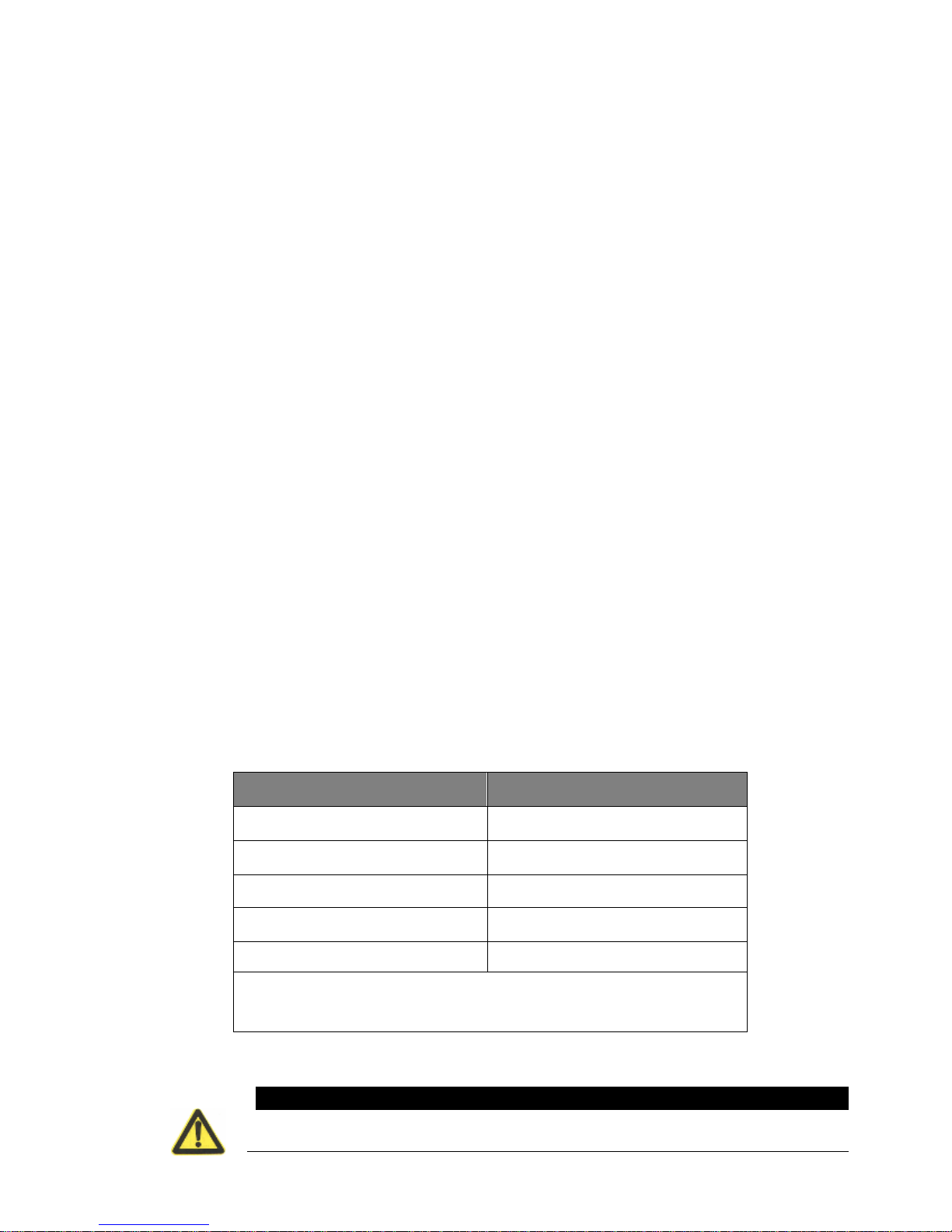
able 8 Battery number Configuration
CAUTION
● The following process must be performed if the UPS is connected with
generator.
All UPS and EBP Cabinets
Number of Battery Strings
UPS only (internal batteries)
1(default)
UPS+1EBP
3
UPS+2EBPs
5
UPS+3EBPs
7
UPS+4EBPs
9
NOTE The UPS contains one battery string; each EBP contains two
battery strings.
Page 32
UPServer2.0
ON-LINE DOUBLE CONVERSION
● First, turn on the generator, after it runs stably connect output power of the
generator to UPS input terminal, then turn on the UPS. After the UPS is turned
on, please connect load one by one.
● It is recommended that the generator capacity is as twice as the UPS rated
capacity.
● You had better not use the ECO mode when the quality of the input AC mains is
not good.
5 COMMUNICATION RS232, USB, OPTIONALS AND EPO
This section describes the:
● Communication ports (RS-232 and USB)
● Connectivity cards
● Emergency Power-off (EPO)
● Load Segments
● UPSilon2000 Power Management Software
Installing Communication Options and Control Terminals
To install the communication options and control terminals:
1. Install the appropriate connectivity card and/or necessary cable(s) and
connect the cables to the appropriate location.
2. Route and tie the cable(s) out of the way.
3. Continue to “Operation” on page 26/28 to start up the UPS.
Communication Options
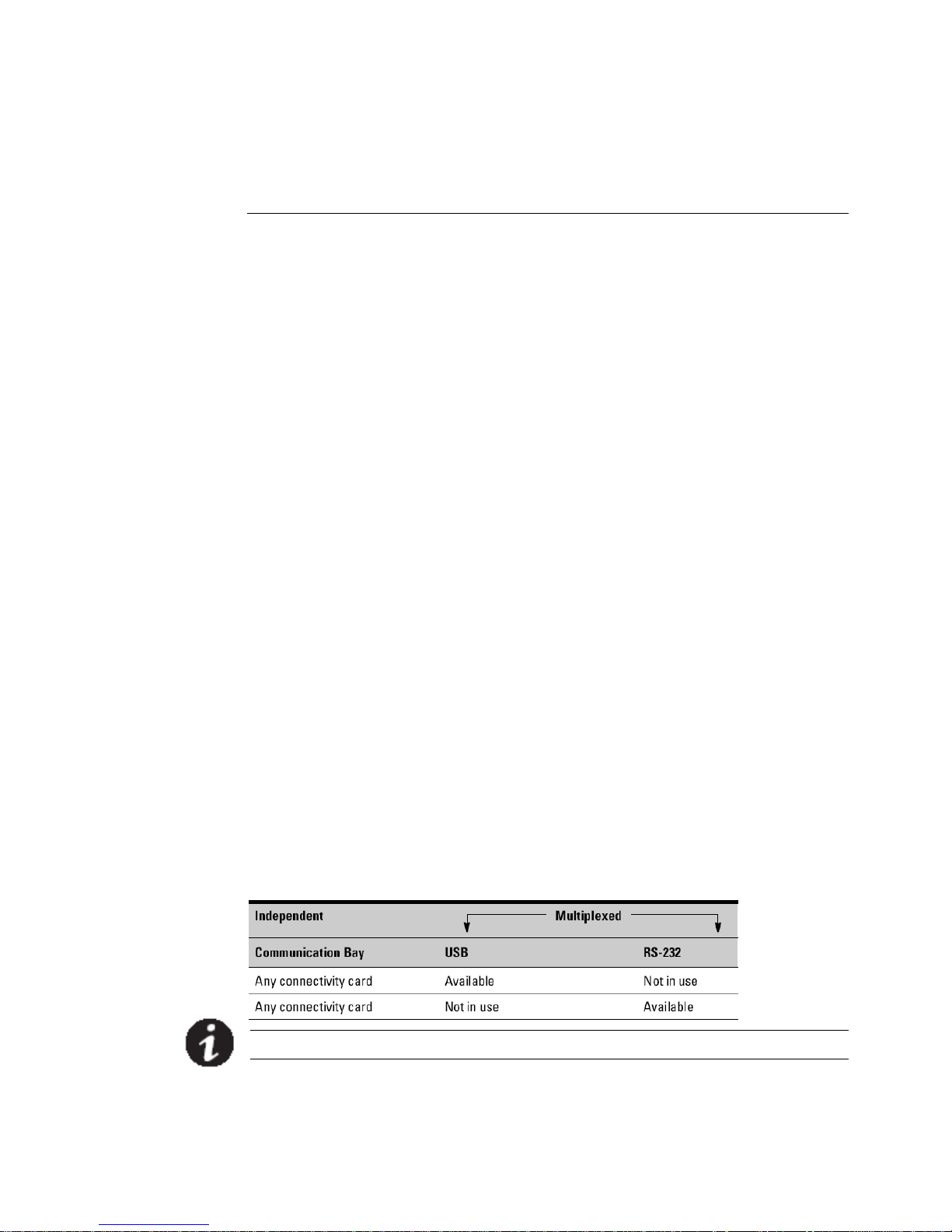
The UPS has serial communication capabilities through the USB and RS-232
communication ports or through a connectivity card in the available
communication bay. The UPS supports two serial communication devices
according to the following table:
NOTE:The communication speed of the RS232 port is fixed at 2400 bps.
RS-232 and USB Communication Ports
To establish communication between the UPS and a computer, connect your computer to one of
the UPS communication ports using an appropriate communication cable (not supplied). See
Page 33

UPServer2.0
ON-LINE DOUBLE CONVERSION
Figure 20,21 for the communication port locations.
When the communication cable is installed, power management software can exchange data with
the UPS. The software polls the UPS for detailed information on the status of the power
environment. If a power emergency occurs, the software initiates the saving of all data and an
orderly shutdown of the equipment. The cable pins for the RS-232 communication port are
identified in Figure 22 and the pin functions are described in Table 9.
Figure 17 RS-232 Communication Port (DB-9 Connector)
Table 9. RS-232 Communication Port Pin Assignment
Pin Number Function Definition Direction from the UPS
1、4、6、7、8、9 No use --
2 R×D(Transmit to external device) Out
3 TxD(Receive from external device) In
5 GND(Signal common) --
Connectivity Cards
Connectivity cards allow the UPS to communicate in a variety of
networking environments and with different types of devices. The UPS has one
available communication bay for the following connectivity cards:
● Web/SNMP Card - has SNMP and HTTP capabilities as well as monitoring
through a Web browser interface; connects to a twisted-pair Ethernet
(10/100BaseT) network. In addition, a Environmental Monitoring Probe can be
attached to obtain humidity, temperature, smoke alarm, and security
information.
● Relay Interface Card - has isolated dry contact relay outputs for UPS status:
Utility failure, Low battery, UPS alarm/OK, or On bypass.
See Figure 20, for the location of the communication bay.
NOTE:Before installing the connectivity card , please remove the clip from the
bay. Refer to the user’s manual of the appropriate cards.
Page 34
UPServer2.0
ON-LINE DOUBLE CONVERSION
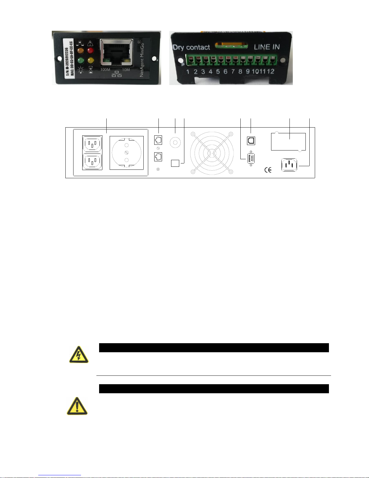
Figura 18
SNMP card RELAY card
2
5
3 4
7
6 8 1
Figure 19 UPS rear view
1) Input plugin
2) UPS output outlets
3) Thermal fuse
4) EPO
5) RJ11/RJ45
6) RS-232 port
7) USB port
8) Optiona slot for communication
Emergency Power-off
EPO is used to shut down the UPS from a distance. This feature can be used for shutting down the
load and the UPS by thermal relay, for instance in the event of room overtemperature. When EPO
is activated, the UPS shuts down the output and all its power converters immediately. The UPS
remains on to alarm the fault.
There is also a front panel EPO option for user to initial EPO function by pressing the three switch
on the front panel together. When the three switches is pressed down at the same time, the EPO
function will be actived, UPS will shutdown and the buzzer will long beep. Pressing startup
switches will not turn on the UPS unless the EPO function is deactived by pressing the three
switches together and press off switches to return normal status.
WARNING
The EPO circuit is an IEC 60950 safety extra low voltage (SELV) circuit. This
circuit must be separated from any hazardous voltage circuits by reinforced
insulation.
CAUTION
● The EPO must not be connected to any utility connected circuits. Reinforced
insulation to the utility is required. The EPO switch must have a minimum rating
of 24 Vdc and 20 mA and be a dedicated latching-type switch not tied into
another circuit. The EPO signal must remain active for at least 250 ms for proper
operation.
● To ensure the UPS stops supplying power to the load during any mode of
Page 35
UPServer2.0
ON-LINE DOUBLE CONVERSION
operation, the input power must be disconnected from the UPS when the
emergency power-off function is activated.
NOTE For Europe, the emergency switch requirements are detailed in
Harmonized document HD-384-48 S1, “Electrical Installation of the Buildings,
Part 4: Protection for Safety Chapter 46: Isolation and Switching.”
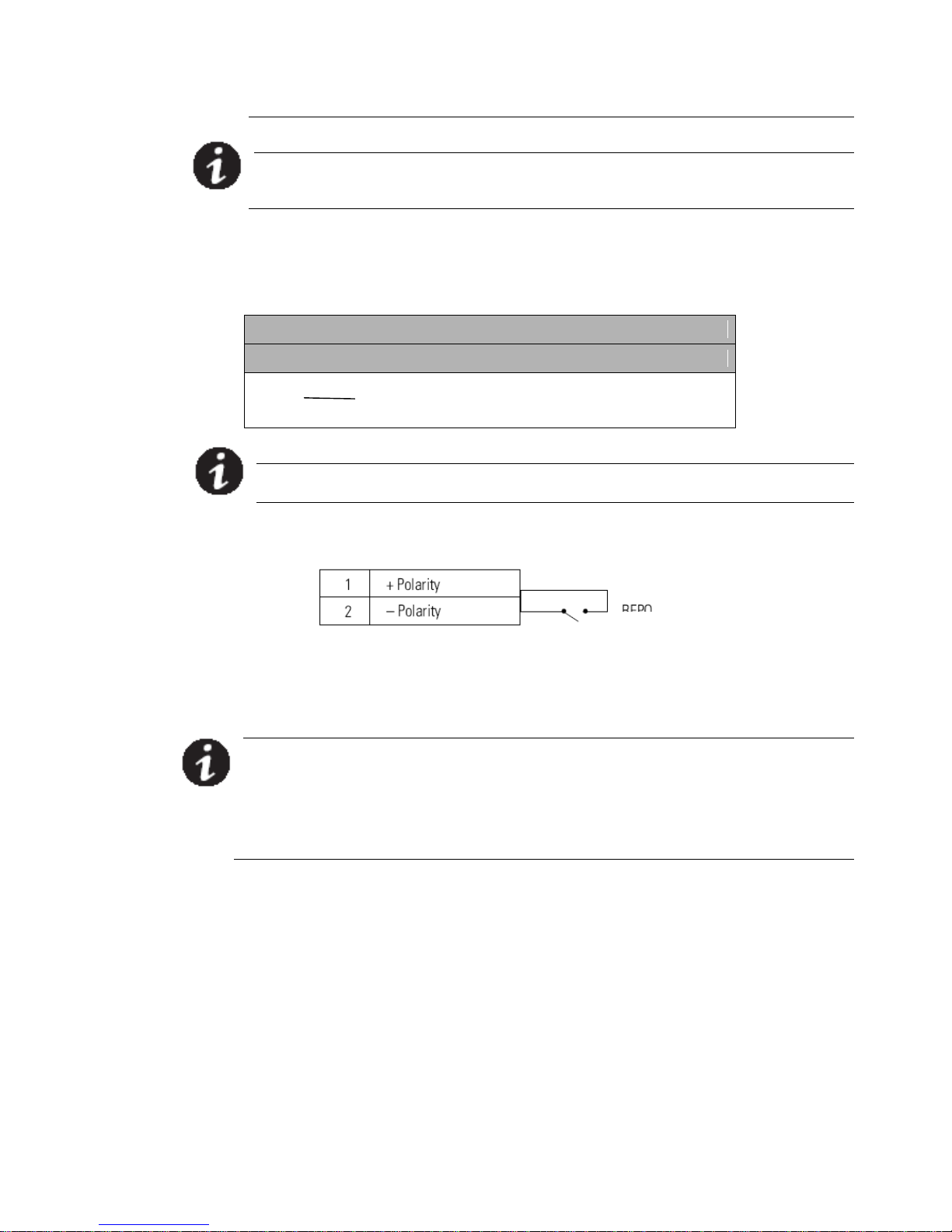
EPO Connections
Wire Function Terminal Wire Size Rating Suggested Wire Size
EPO L1
4–0.32 mm2 (12–22 AWG) 0.82 mm2 (18 AWG)
L2
NOTE Leave the EPO connector installed onto the EPO port of the UPS
even if the EPO function is not needed.
See Figure 20, for EPO location.
Figure 20 EPO Connections
You can set the EPO polarity. See the “EPO Input Polarity” setting in “User
Settings”
NOTE Depending on user configuration, the pins must be shorted or opened to
keep the UPS running. To restart the UPS, reconnect (re-open) the EPO connector
pins and turn on the UPS manually. Maximum resistance in the shorted loop is 10
ohm.
NOTE Always test the EPO function before applying your critical load to avoid
accidental load loss.
EPO
Page 36

UPServer2.0
ON-LINE DOUBLE CONVERSION
UPSilon2000 Power Management Software
Each UPS ships with UPSilon2000 Power Management Software. To begin
installing UPSilon2000 software, see the instructions accompanying the Software
Suite CD.
NOTE Install UPSilon2000 power management software with the serial number
attched on the cover of the CD .When running the monitor software , choose
appropriate communication port. If using RS232, choose COM1/2 and Megatec
protocol. If using USB, choose megatec USB.
UPSilon2000 software provides up-to-date graphics of UPS power and system
data and power flow. It also gives you a complete record of critical power events,
and it notifies you of important UPS or power information. If there is a power
outage and the UPS battery power becomes low, UPSilon2000 software can
automatically shut down your computer system to protect your data before the
UPS shutdown occurs.
6 UPS Maintenance
UPS and Battery Care
For the best preventive maintenance, keep the area around the UPS clean and
dust‐free. If the atmosphere is very dusty, clean the outside of the system with a
vacuum cleaner. For full battery life, keep the UPS at an ambient temperature of
25°C (77°F).
NOTE The batteries in the UPS are rated for a 3–5 year service life. The length of
service life varies, depending on the frequency of usage and ambient
temperature. Batteries used beyond expected service life will often have severely
reduced runtimes. Replace batteries at least every 5 years to keep units running
at peak efficiency.
Storing the UPS and Batteries
If you store the UPS for a long period, recharge the battery every 6 months by
connecting the UPS to utility power. The internal batteries charge to 80%
capacity in less than 5 hours. However, we recommends that the batteries charge
for 48 hours after long-term storage.
Replacing Batteries
NOTE DO NOT DISCONNECT the batteries while the UPS is in Battery mode.。
The EBP can be replaced when UPS is ON, but be aware that if the utility fails at
that time , the load of the UPS may NOT be protected.
Page 37
UPServer2.0
ON-LINE DOUBLE CONVERSION
Replacing Tower EBPs
CAUTION
The EBP is heavy. Lifting the cabinet requires a minimum of two people.
1. Unplug the EBP cable from the UPS. If additional EBPs are installed, unplug the EBP cable from
the battery connector on each EBP.
2. Replace the EBP(s). See “Recycling the Used Battery or UPS” on page 62 for proper disposal.
3. For each replaced EBP, remove the cable retention clip covering the battery connector(s), as
shown in Figure 17 on page 25. Retain the clips.
4. Plug the EBP cable(s) into the battery connector(s) as shown in Figure 17 on page 25. Up to four
EBPs may be connected to the UPS.
5. Retain the removed clips.
6. Verify that the EBP connections are tight and that adequate bend radius and strain relief exist
for each cable.
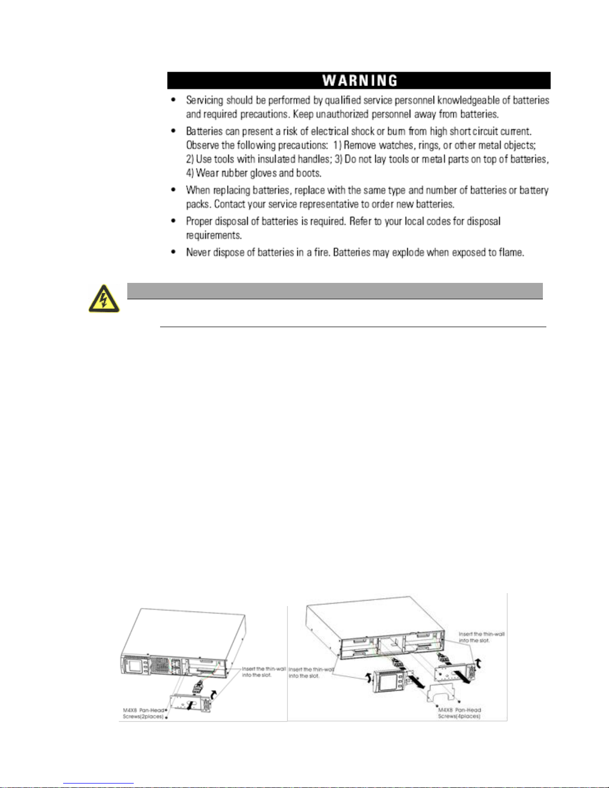
Replacing RT UPS and EBPS
1. If the battery fault, the following steps are provided for modular unit to replace the new
battery pack
2. Remove the front cover of the battery box.
3. Remove the connection cables between battery box and UPS. Release the screw of the
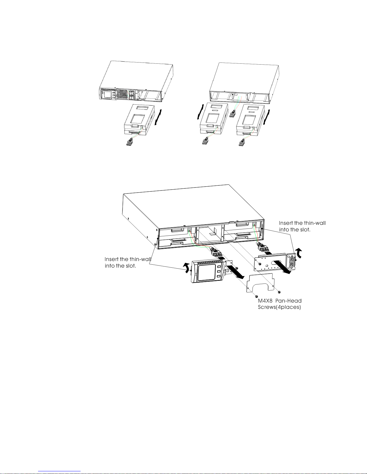
baffle of the battery pack as the Fig26 shows, then remove the baffle from the left or right.
Page 38
UPServer2.0
ON-LINE DOUBLE CONVERSION
Figura 21 The Installation for baffle of battery pack
4. Grasp the handle in front of the battery pack, take out of it and hold it, then remove the battery
pack as fig. 27 shown.
Figura 22 Rimozione pacco batterie
5.Hold the middle of the new battery pack, insert it. Once install the new battery pack, make sure it is
completely inserted into the chassis as fig 23 shown
Figure 23
Installation
for battery
pack
Testing New Batteries
To test new batteries:
1. Plug the UPS into a power outlet for 48 hours to charge the
batteries.
2. Start up the UPS by pressing the start up combination button.
3. Press the battery test combination button to activate the battery test.
The UPS starts a battery test if the batteries are fully charged, the
UPS is in Normal mode with no active alarms, and the bypass
voltage is acceptable.
During the battery test, the UPS transfers to Battery mode and
discharges the batteries for 10 seconds. The LED indicators of the front cover
stop cycling when the test is completed.
Page 39
UPServer2.0
ON-LINE DOUBLE CONVERSION
Recycling the Used Battery or UPS
Contact your local recycling or hazardous waste center for information on proper
disposal of the used battery or UPS.
WARNING
Do not dispose of the battery or batteries in a fire. Batteries may explode.
Proper disposal of batteries is required. Refer to your local codes for disposal
requirements.
Do not open or mutilate the battery or batteries. Released electrolyte is
harmful to the skin and eyes. It may be toxic.
7. TECHNICAL SPECIFICATION
Table 10. Communication ports (standard and optional)
OPTIONAL BOARDS
SNMP o Relay contatti puliti
STANDARD PORTS
RS232 (DB-9): 2400 bps
USB
Table 11 Battery cabinet voltage (EBP)
Model EBP
Configuration
Battery Voltage
UPS power
UPserver2.0
Rack / Tower
24Vdc
2000 VA
Table 12. UPS Model
Model
Power
UPS rear view
UPserver 2.0
2000VA / 1350W
Figura 19
Table 13. Weight and dimensions
Model UPS
Dimensionsi (W*D*H)
Weight
UPserver 2.0
440*430*86.5 mm
15.7 kg
Table 14. Input
Nominal Frequency
50/60 Hz auto-sensing
Frequency Range
45–55 Hz(50Hz)/55-65Hz(60Hz) before switching to battery
Voltage Bypass range
+5%,+10%,+15%,+25% (+25% default)
-20%,-30%,-45% (-45% default)
Table 15. Input
Model
Voltage
Selectable input
voltage
Voltage range at
100% load
UPserver 2.0
230V
200/208/220/230/240
160 - 290 Vac
Table 16. Input electrical connections
Page 40

UPServer2.0
ON-LINE DOUBLE CONVERSION
Model
Connection type
Cable
UPserver 2.0
IEC320 C13-10A
IEC320 C14-10A
Table 17. Output
Nominal Value
200/208/220/230/240V
(Configurable or auto-sensing)
2000 VA
1350 W
Frequency
50 or 60 Hz, auto-sensing
Overload
(Normal operation)
108%±5%–150%±5%: Load transfers to Fault mode after 30 seconds.
150%±5%–200%±5%: Load transfers to Fault mode after 300 ms.
>200%±5%: Load transfers to Fault mode after 20 ms.
Overload
(Bypass mode)
100%±5%–130%±5%: Load transfers to Fault mode after 20 minutes..
130%±5%–150%±5%: Load transfers to Fault mode after 2 minutes.
150%±5%–200%±5%: Load transfers to Fault mode after 15 seconds.
>200%±5%: Load transfers to Fault mode after 140 ms.
Overload
(Battery mode)
108%±5%–150%±5%: Load transfers to Fault mode after 30 seconds..
150%±5%–200%±5%: Load transfers to Fault mode after 300 ms.
>200%±5%: Load transfers to Fault mode after 300 ms.
Voltage Waveform
Sine wave
Harmonic Distortion
<3% THD on linear load; <5% THD on non-linear load
Transfer time
Online mode: 0 ms (no break)
ECO mode: 10ms maximum (due to loss of utility)
Load Crest Factor
3 a 1
Table 18. Output electrical connections
Model
Output connections
Cable
UPserver 2.0
(IEC C13-10A)*2 + 1 Shuko
IEC320 C14-10A
Table 19. Environmental and Safety
Surge
Suppression
EN 61000-2-2
EN 61000-4-2, Livello 4
EN 61000-4-3, Livello 3
EN 61000-4-4, Livello 4
Page 41
UPServer2.0
ON-LINE DOUBLE CONVERSION
EN 6100-4-5, Livello 4 Criterio A
EMC
certifications
CE per IEC/EN 62040-2,
Classe B
EMC (Emission)
IEC 62040-2:ed2:2005 / EN 62040-2:2006
Safety
IEC 62040-1-1, IEC 60950-1
Marking
CE, CB
Operating
temperature
0°C to 40°C (32°F to 104°F) in Online mode, with linear derating for altitude
NOTE Thermal protection switches load to Bypass in case of overheating.
Humidity
0–90% noncondensing
Operataing
altitude
Up to 3,000 meters (9,843 ft) above sea level
Audible Noise
<55 dBA a 1 m typical
Leakage current
<1.5 mA
8. TROUBLESHOOTING
The following messages are the information that users would find on UPS when it meets some
problems. Users can judge if the fault is caused by external factors and know how to deal with it
by making full use of the information.
Fault indicator on, indicates that the UPS has detected some faults. Buzzer beeps, indicates that
UPS need to be paid attention to, if beeps for a long time, it means that there is something wrong
with the machine. If you need help, contact our service department, the following messages
should be provided for analysis:
◆UPS MODEL NO. and SERIAL NO.
◆Date of fault happened
◆ Detailed description of the problem (include indicator
statements on cover)
the following table describes typical alarm conditions.
Table 22.
ault
Cause
Solution
The “INPUT”
letters on LCD
display section
flashes
Anti-connection of
mains live and neutral
or mains is out of
range
Re-connect the input power cable
and make a correct connection
Battery capacity
indicator flashes
Battery low voltage or
battery disconnected
Check UPS battery, connect
battery well, if battery damaged,
replace it
Mains normal, but
UPS has no input
UPS input breaker
open circuit
Press the breaker for reset
Short back up time
Battery not fully
charged
Keep UPS connecting with mains
power for more than 8 hours,
recharge battery
UPS overload
Check the usage of loads, remove
some redundant devices
Page 42

UPServer2.0
ON-LINE DOUBLE CONVERSION
Battery aged
When replace battery, contact
franchiser to get battery and
relative assembly
UPS doesn’t
startup after
pressing the ON
key
Didn’t press the
combination keys of
“on”
Press the two keys at the same
time
UPS has no battery
connected or battery
voltage low and too
many loads connected
Connect UPS battery well, if
battery voltage low, please turn
off UPS and remove some loads,
then start UPS
Fault occurs inside
UPS
Contact supplier for servicing
The icon of
charger status on
LCD display
flashes and buzzer
beeps once per
second
Charger doesn’t
work normally or
battery aged
Contact supplier for servicing
Page 43

UPServer2.0
ON-LINE DOUBLE CONVERSION
WARRANTY
Dear Customer,
Thank you for purchasing a NAICON product. We hope that you be satisfied. If the product fails in warranty period, please contact your
dealer or call +39 02 950031 or go to www.naicon.com/elsist. Before contacting your dealer or authorized service network, we recommend
that you read the operating and maintenance manual carefully.
With this warranty, NAICON warrants the product to be defective in materials or workmanship for 2 years, as of the original delivery date.
If there are material or manufacturing defects during the warranty period, ELSIST affiliates, Authorized Service Centers or authorized
resellers located in the EEC will repair or (at ELSIST discretion) replace the defective product or components under the terms and conditions
below, without any charge for labor or spare parts costs. ELSIST reserves the right (in its sole discretion) to replace the components of
defective products or low cost products with assembled parts or new or refurbished products.
Conditions.
1. This warranty will only be valid if the defective product is returned together with the sales invoice.
ELSIST reserves the right to refuse warranty service in the absence of such documents or if the information contained therein is
incomplete or illegible.
2. This warranty does not cover the costs and / or any damages and / or defects resulting from any modifications or adjustments
made to the product, without prior written permission from ELSIST, in order to adapt the product to local technical or safety
standards in countries other than those for which the product was originally designed and manufactured.
3. This warranty will be void if the model or serial number indicated on the product has been modified, deleted, removed or otherwise
illegible.
4. Are excluded by the warranty:
Periodic maintenance and repair or replacement of parts subject to normal wear and tear.
Any modification or modification to the product, without prior written permission from ELSIST to enhance performance than those
described in the User and Maintenance Manual
• All costs of technical staff support and any transport from the customer's adress to Assistance Center and vice versa as well
as all the risks involved.
Damages due to:
a. Improper use, including but not limited to: (a) the use of the product for any purpose other than the intended use or failure
to observe the ELSIST instructions for correct use and maintenance of the product, (b) installation or use of the product
not complying with the Technical or Safety standards in the country in which it is used.
b. Repairs by unauthorized personnel or by the Customer himself.
c. Accidental events, lightning, floods, fires, incorrect ventilation or other causes not attributable to ELSIST.
d. Defects of the equipment or equipment to which the product was connected.
5. This warranty does not affect the buyer's rights established by applicable national laws nor the Customer's rights to the reseller
arising out of the sales contract.
Unless authorized by the manufacturer, reproduction of any part of this manual is prohibited. Our equipment, built with the utmost care and
with selected components, is controlled by ELSIST Quality Services. However, if you notice any anomalies, please inform us by calling
02-950031 specifying serial number and model of the devide, which are printed on the identification plate at the rear side of the UPS.
ELSIST Assistance Service is also available to collect requests, comments, suggestions, if any.
In case of failure:
Contact our Customer Service Center at +39 02 95 0031, and verify the UPS malfunction.
If the products returned to NAICON were OPERATING or if they were delivered without our permission or for out-of-warranty products, they
will be returned to the customer by charging a cost that will depend on the country where will be shipped.
END OF DOCUMENT
 Loading...