

Elsist POLARIS 10, POLARIS 15, POLARIS 20, POLARIS 30, POLARIS 40 Instruction Manual
...
Electrical System for Continuity
P
PP
Polaris
3333
Phase
10
1010
10----16
1616
160
00
0
Kva
INSTRUCTION MANUAL

POLARIS 10●15●20●30●40●60●80●100●120●160
TRIPHASE-TRIPHASE
Rev. 04 – 06 December 2016
2
Contents
1....Safety ............................................................................................................................................... 3
1.1 Safety notes .............................................................................................................................. 3
1.2 Symbols used in this guide ....................................................................................................... 3
2....Main Features ................................................................................................................................. 3
2.1 Summarization .......................................................................................................................... 3
2.2 Functions and Features ............................................................................................................ 3
3....Installation....................................................................................................................................... 4
3.1 Unpack checking ...................................................................................................................... 4
3.2 Cabinet Outlook ........................................................................................................................ 4
3.3 Display control panel ................................................................................................................ 6
3.4 Installation notes ....................................................................................................................... 6
3.5 External Protective Devices ...................................................................................................... 7
3.6
Power Cables
............................................................................................................................ 7
3.7 Power cable connect ................................................................................................................. 9
3.8 Battery connection .................................................................................................................. 10
3.9 UPS parallel Installation .......................................................................................................... 11
3.10 Computer access (CD MUSER4000 optional) ..................................................................... 12
4....Operation ...................................................................................................................................... 13
4.1 Operation Modes ..................................................................................................................... 13
4.2 Turn on/off UPS ...................................................................................................................... 13
4.3 The TFT Color Display............................................................................................................ 18
4.4 Parameters Display & Setting ................................................................................................ 21
4.5 Display Messages/Troubleshooting ....................................................................................... 23
4.6 Options ................................................................................................................................... 24
Appendix 1 Specifications ................................................................................................................ 25
Appendix 2 Problems and Solution ................................................................................................. 29
Appendix 3 USB communication port definition............................................................................ 30
Appendix 4 RS232 communication port definition ........................................................................ 30
Appendix 5 RS485 communication port definition ........................................................................ 31
Appendix 6 Dry contact communication port definition ............................................................... 31
Appendix 7 REPO instruction........................................................................................................... 32
Appendix 8 Accessories ................................................................................................................... 32
Appendix 9 Efficiency Chart ............................................................................................................. 33
Publish statement
Thank you for purchasing this series UPS.
This series UPS is an intelligent, three phase in Three phase out, high frequency online UPS designed by our R&D team who is with years
of designing experiences on UPS. With excellent electrical performance, perfect intelligent monitoring and network functions, smart
appearance, complying with EMC and safety standards, The UPS meets the world’s advanced level.
Read this manual carefully before installation
This manual provides technical support to the operator of the equipment.
All rights reserved.
The information in this document is subject to change without notice.

POLARIS 10●15●20●30●40●60●80●100●120●160
TRIPHASE-TRIPHASE
Rev. 04 – 06 December 2016 3
1. SAFETY
Important safety instructions - Save these instructions
There exists dangerous voltage and high temperature inside the UPS. During the installation, operation
and maintenance, please abide the local safety instructions and relative laws, otherwise it will result in
personnel injury or equipment damage. Safety instructions in this manual act as a supplementary for the
local safety instructions. Our company will not assume the liability that caused by disobeying safety
instructions.
1.1 Safety notes
1. Even no connection with utility power, 220/230/240VAC voltage may still exist at UPS terminal !
2. For the sake of human being safety, please well earth the UPS before starting it.
3. Don’t open or damage battery, for the liquid spilled from the battery is strongly poisonous and do harmful
to body!
4. Please avoid short circuit between anode and cathode of battery, otherwise, it will cause spark or fire!
5. Don’t disassemble the UPS cover, or there may be an electric shock!
6. Check if there exists high voltage before touching the battery
7. Working environment and storage way will affect the lifetime and reliability of the UPS. Avoid the UPS
from working under following environment for long time
◆ Area where the humidity and temperature is out of the specified range(temperature 0 to 40°C, relative
humidity 5%-95%)
◆ Direct sunlight or location nearby heat
◆ Vibration Area with possibility to get the UPS crashed.
◆ Area with erosive gas, flammable gas, excessive dust, etc
8. Keep ventilations in good conditions otherwise the components inside the UPS will be over-heated which
may affect the life of the UPS.
1.2 Symbols used in this guide
WARNING! Risk of electric shock
CAUTION! Read this information to avoid equipment damage
2. MAIN FEATURES
2.1 Summarization
This series UPS is a kind of three-in-three-out high frequency online UPS.
The UPS can solve most of the power supply problems, such as blackout, over-voltage, under-voltage,
voltage sudden drop, oscillating of decreasing extent, high voltage pulse, voltage fluctuation, surge,
inrush current, harmonic distortion (THD), noise interference, frequency fluctuation, etc..
This UPS can be applied to different applications from computer device, automatic equipment,
communication system to industry equipment.
2.2 Functions and Features
◆ 3Phase In/3Phase Out UPS
It is 3Phase In/3Phase Out high-density UPS system, of which input current is kept in balance. No
unbalance problem might occur.
◆ Digital Control
This series UPS is controlled by Digital Signal Processor (DSP); enhance, it increases reliability,
performance, self-protection, and self-diagnostics and so on.
◆ Battery Configurable
10-30kVA: from 16 blocks to 20 blocks, the battery voltage of this series UPS can be configured at 16
blocks, 18 blocks or 20 blocks according to your convenience.
40kVA: from 32 blocks to 40 blocks, the battery voltage of this series UPS can be configured at 32 blocks,
34 blocks, 36 blocks, 38 blocks or 40 blocks according to your convenience.
POLARIS 10●15●20●30●40●60●80●100●120●160
TRIPHASE-TRIPHASE
Rev. 04 – 06 December 2016
4
◆ Charging Current is configurable
Via setting tool, the user may set the capacity of the batteries as well as reasonable charging current as
well as maximum charging current. Constant voltage mode, constant current mode or floating mode can
be switched automatically and smoothly.
◆
◆◆
◆ Intelligent Charging Method
The series UPS adopts advanced three-stage charging method:
1st stage: high current constant current charging to guarantee to charge back to 90%;
2nd-stage: Constant Voltage in order to vitalize battery and make sure batteries are fully charged
3rd stage: floating mode.
With this 3-stage charging method, it extends the life of the batteries and guarantees fast charging.
◆
◆◆
◆ LCD Display
With LCD plus LED displays, the user may easily get UPS status and its operational parameters, such as
input/output voltage, frequency & load%, battery % and ambient temperature, etc...
◆
◆◆
◆ Intelligent Monitoring Function
Via optional SNMP Card, you may remotely control and monitor the UPS.
◆
◆◆
◆ EPO Function
The series UPS may be completely shut off when the EPO is pressed. REPO function (Remote EPO) is
also available in this series UPS.
3. INSTALLATION
3.1 Unpack checking
1. Don’t lean the UPS when moving it out from the packaging
2. Check the appearance to see if the UPS is damaged or not during the transportation, do not switch
on the UPS if any damage found. Please contact the dealer right away.
3. Check the accessories according to the list at Appendix 8 and contact the dealer in case of missing
parts.
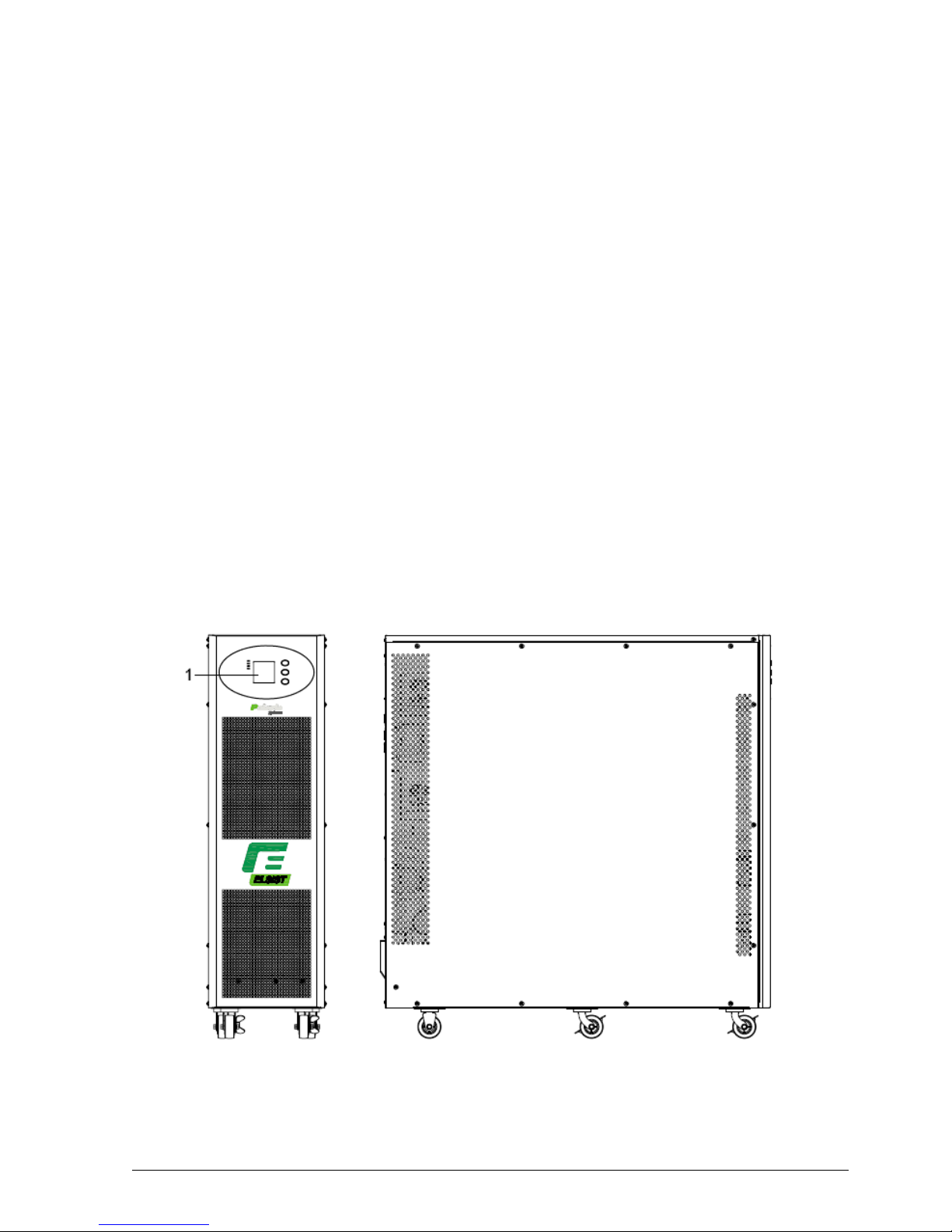
3.2 Cabinet Outlook
Front View Side View
POLARIS 10●15●20●30●40●60●80●100●120●160
TRIPHASE-TRIPHASE
Rev. 04 – 06 December 2016
5
1)
TFT color display panel
2)
RS485 port
3)
Dry contact port
4)
Parallel port 1
5)
USB port
6)
Parallel port 2
7) RS232 port
8)
Power Switch
9)
REPO port
10)
I/P Switch
11)
Terminal block for Input, output & battery
12)
Intelligent Slot 1 (SNMP card/ Relay card)
13)
Maintenance switch & its cover
14)
Intelligent Slot 2 (SNMP card/ Relay card)
15)
O/P Switch
16)
Ground
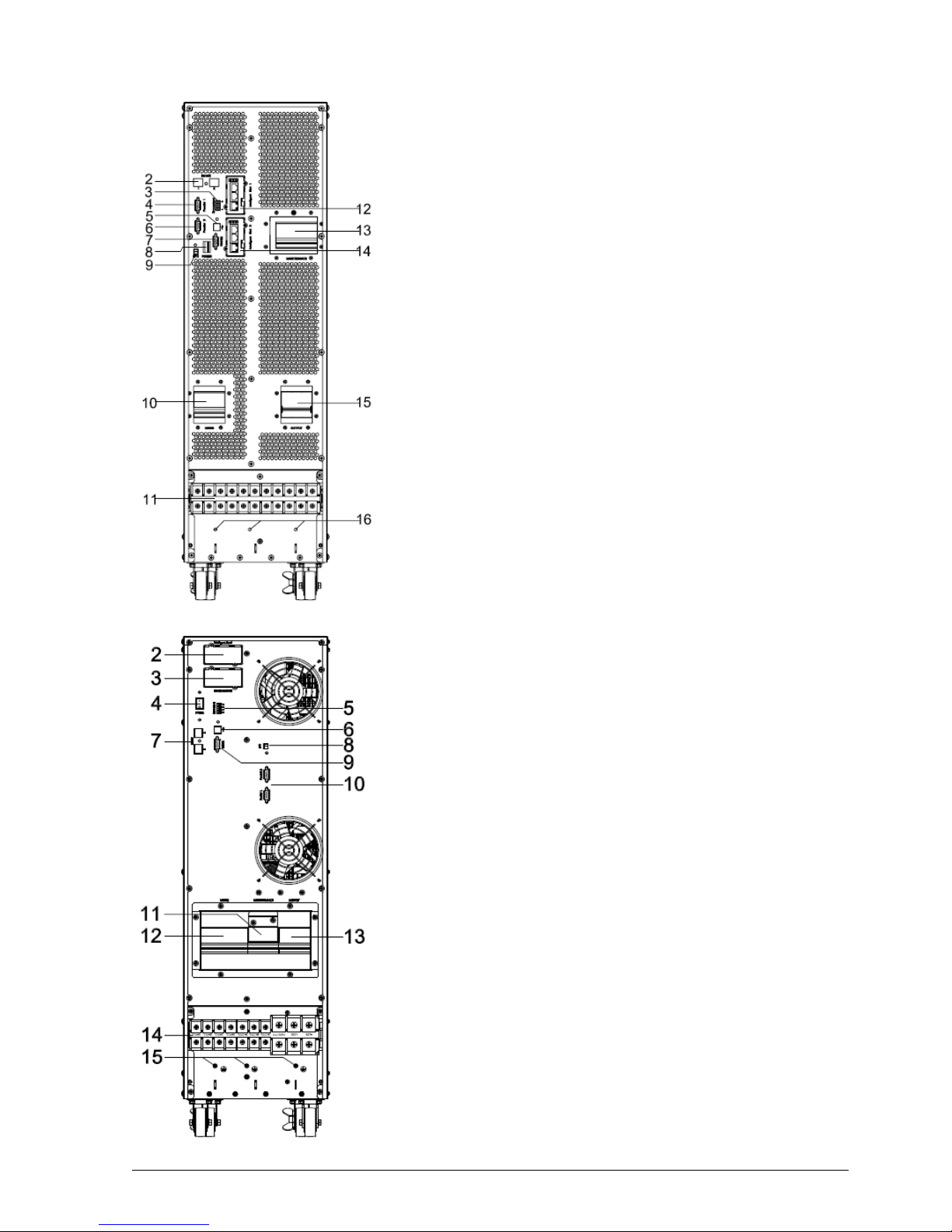
10-20KVA Rear View (terminal block without cover)
1)
TFT color display panel
2)
Intelligent Slot 1 (SNMP card/ Relay card)
3)
Intelligent Slot 2 (SNMP card/ Relay card)
4)
Power Switch
5)
Dry contact port
6)
USB port
7)
RS485 port
8)
REPO port
9)
RS232 port
10)
Parallel port (1-2)
11)
Maintenance switch & its cover
12)
I/P Switch
13)
O/P Switch
14)
Terminal block for Input, output & battery
15)
Ground
30-160KVA Rear View (terminal block without cover)
POLARIS 10●15●20●30●40●60●80●100●120●160
TRIPHASE-TRIPHASE
Rev. 04 – 06 December 2016
6
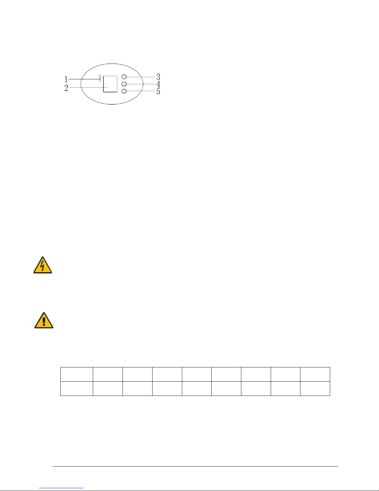
3.3 Display control panel
1) LED (from top to bottom: alarm / bypass / battery / inverter”)
2) TFT color display
3) Scroll button
4) Off button
5) On button (battery cold start switch)
3.4 Installation notes
Note: Consider for the convenience of operation and maintenance, the space in front and back of the
cabinet should be left at least 100cm and 80cm respectively when installing the cabinet.
◆ Please place the UPS in a clean, stable environment, avoid the vibration, dust, humidity, flammable gas
and liquid, corrosive. To avoid from high room temperature, a system of room extractor fans is
recommended to be installed. Optional air filters are available if the UPS operates in a dusty
environment.
◆ The environment temperature around UPS should keep in a range of 0°C ~40°C. If the environment
temperature exceeds 40°C, the rated load capacity s hould be reduced by 12% per 5°C. The max
temperature can't be higher than 50°C.
◆ If the UPS is dismantled under low temperature, it might be in a condensing condition. The UPS can't be
installed unless the internal and external of the equipment is fully dry. Otherwise, there will be in danger
of electric shock.
◆ Batteries should be mounted in an environment where the temperature is within the required specs.
Temperature is a major factor in determining battery life and capacity. In a normal installation, the battery
temperature is maintained between 15°C and 25°C. Ke ep batteries away from heat sources or main air
ventilation area, etc.
WARNING!
Typical battery performance data are quoted for an operating temperature between 20°C and
25°C. Operating it above this range will reduce the battery life while operation below this range
will reduce the battery capacity.
◆ Should the equipment not be installed immediately it must be stored in a room so as to protect it against
excessive humidity and or heat sources.
CAUTION!
An unused battery must be recharged every 6months Temporarily connecting the UPS to a
suitable AC supply mains and activating it for the time required for recharging the batteries.
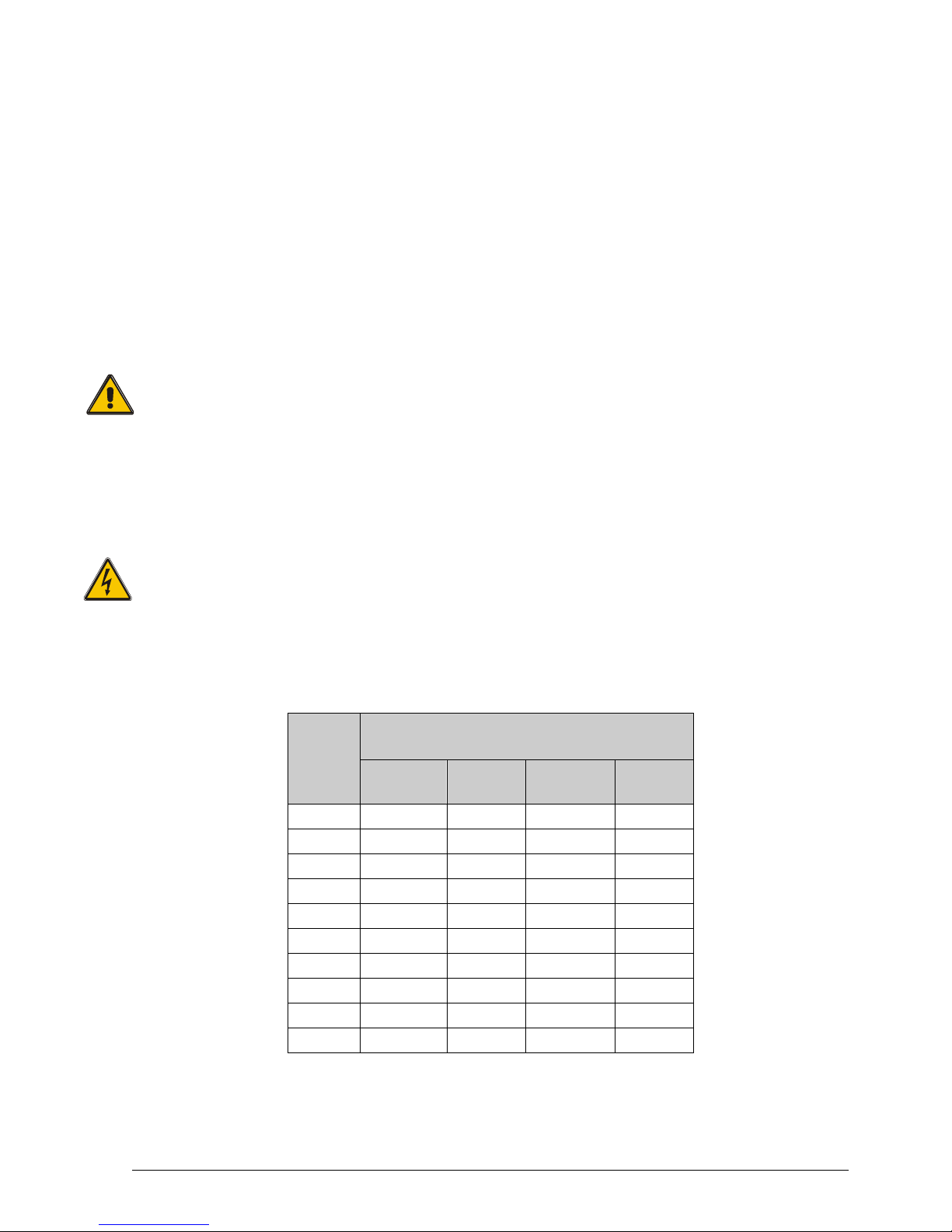
◆ The highest altitude that UPS may work normally with full load is 1500 meters. The load capacity should
be reduced when this UPS is installed in place whose altitude is higher than 1500 meters, shown as the
following table:
(Load coefficient equals max load in high altitude place divided by nominal power of the UPS)
Altitude
(Mt)
1500 2000 2500 3000 3500 4000 4500 5000
Load
coefficient
100% 95% 90% 85% 80% 75% 70% 65%
◆ The UPS cooling is depending on fan, so it should be kept in good air ventilation area. There are many
ventilation holes on the front and rear, so they should not be blocked by any obstacles.
POLARIS 10●15●20●30●40●60●80●100●120●160
TRIPHASE-TRIPHASE
Rev. 04 – 06 December 2016
7
3.5 External Protective Devices
For safety reasons, it is necessary to install, external circuit breaker at the input A.C. supply and the
battery. This chapter provides guidelines for qualified installers that must have the knowledge of local
wiring practices for the equipment to be installed.
◆ External Battery
The UPS and its associated batteries are protected against the effect of over-current through a DC
compatible thermo-magnetic circuit-breaker (or a set of fuses) located close to the battery.
◆ UPS Output
Any external distribution board used for load distribution shall be fitted with protective devices that may
avoid the risk of UPS overloaded.
◆ Over-current
Protection device shall be installed at the distribution panel of the incoming main supply. It may identify
the power cables current capacity as well as the overload capacity of the system.
CAUTION!
Select a thermo magnetic circuit-breaker with an IEC 60947-2 trip curve C (normal) for 125% of
the current as listed below.
3.6
Power Cables
◆ The cable design shall comply with the voltages and currents provided in this section, Kindly follow
local wiring practices and take into consideration the environmental conditions (temperature and
physical support media).
WARNING!
Upon starting. Please ensure that you are aware of the location and operation of the external
isolators which are connected to the UPS input/bypass supply of the mains distribution panel.
Check to see if these supplies are electrically isolated. And post and necessary warning signs to
prevent any inadvertent operation.
◆ For future expansion purpose, it is economical to install power cable according to the full rating capacity
initially. The diameter of cable is shown below:
UPS
CABLE DIMENSION (mm2)
AC
Input
AC
Output
DC
Input
Ground
10KVA
4 x 10 4 x 10
10
10
15KVA
4 x 10
4 x 10
16 10
20KVA
4 x 16
4 x 16
20 16
30KVA
4 x 16 4 x 16
3 x 35 16
40KVA
4 x 16 4 x 16
3 x 16 16
60KVA
4 x 35 4 x 35
3 x 50 35
80KVA
4 x 35 4 x 35
3 x 35 35
100KVA
4 x 50 4 x 50
3 x 70 50
120KVA
4 x 50 4 x 50
3 x 50 50
160KVA
4 x 70 4 x 70
3 x 70 50

POLARIS 10●15●20●30●40●60●80●100●120●160
TRIPHASE-TRIPHASE
Rev. 04 – 06 December 2016
8
CAUTION!
Protective earth cable: Connect each cabinet to the main ground system. For Grounding
connection, follow the shortest route possible.
WARNING!
Failure to follow adequate earthing procedures may result in electromagnetic interference or in
hazards involving electric shock and fire
UPS - TABLE BREAKERS
UPS MODEL 10KVA 15KVA 20KVA 30KVA 40KVA
60KVA
(2X30KVA)
INPUT breaker
3P 20A/400Vac 3P 32A/400Vac 3P 40A/400Vac 3P 63A/400Vac 3P 80A/400Vac 2x 3P 63A/400Vac
OUTPUT breaker
3P 20A/400Vac 3P 32A/400Vac 3P 40A/400Vac 3P 63A/400Vac 3P 100A/400Vac 2x 3P 63A/400Vac
BY-PASS breaker
4P 63A/400Vac 3P 63A/400Vac 3P 100A/400Vac 2x 3P 63A/400Vac
Internal Battery Fuse
63A/500Vdc 100A/500Vdc 120A/500Vdc 200A/500Vdc 2x 200A/500Vdc
UPS MODEL
80
KVA
(2X40KVA)
100
KVA
(3X30KVA)
120KVA
(3X40KVA)
160KVA
(4X40KVA)
INPUT breaker
2x
3P 80A/400Vac
3x
3P 63A/400Vac
3x
3P 80A/400Vac
4x
3P 80A/400Vac
OUTPUT breaker
2x
3P 100A/400Vac
3x
3P 63A/400Vac
3x
3P 100A/400Vac
4x
3P 100A/400Vac
BY-PASS breaker
2x
3P 100A/400Vac
3x
3P 63A/400Vac
3x
3P 100A/400Vac
4x
3P 100A/400Vac
Internal Battery Fuse
2x 200A/500Vdc 3X 200A/500Vdc 4X 200A/500Vdc
BATTERY CABINET - TABLE BREAKERS
UPS MODEL 10KVA 15KVA 20KVA 30KVA 40KVA
60KVA
(2X30KVA)
BATTERY breaker
4P 63A/440Vac (2P BAT+/ 2P BAT-)
4P 125A/400Vac
(2P BAT+/ 2P BAT-)
2x
4P 125A/400Vac
(2P BAT+/ 2P
BAT-)
Internal Battery Fuse
120A/500Vdc (BAT+/BAT-)
200A/500Vdc
(BAT+/BAT-)
2x
200A/500Vdc
(BAT+/BAT-)
UPS MODEL
80
KVA
(2X40KVA)
100
KVA
(3X30KVA)
120KVA
(3X40KVA)
160KVA
(4X40KVA)
BATTERY breaker
2x
4P 125A/400Vac
(2P BAT+/ 2P
BAT-)
3x
4P 125A/400Vac
(2P BAT+/ 2P BAT-)
4x
4P 125A/400Vac
-)
Internal Battery Fuse
2x
200A/500Vdc
(BAT+/BAT-)
3x
200A/500Vdc
(BAT+/BAT-)
4x
200A/500Vdc
(BAT+/BAT-)
POLARIS 10●15●20●30●40●60●80●100●120●160
TRIPHASE-TRIPHASE
Rev. 04 – 06 December 2016
9
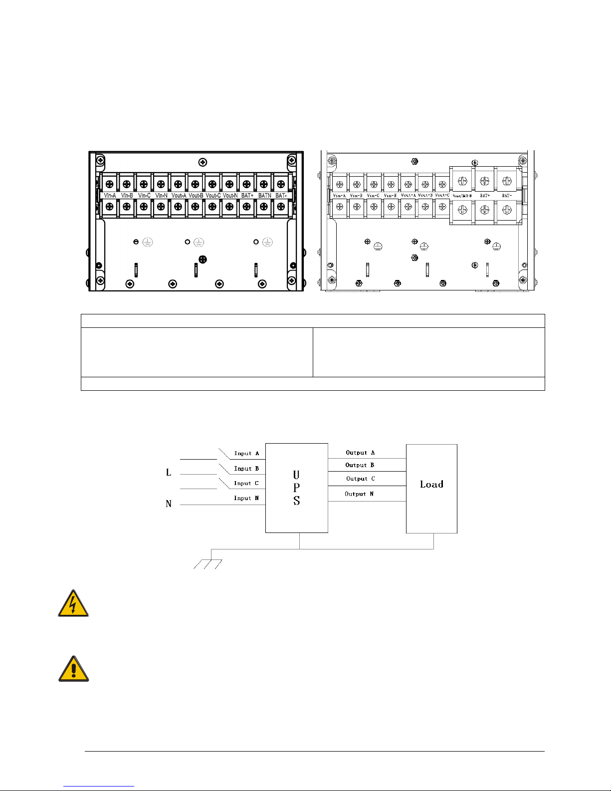
3.7 Power cable connect
Once the equipment has been finally positioned and secured, connect the power cables as described in
the following procedure.
Verify the UPS is totally isolated from its external power source and also all power isolators of the UPS
are open. Check to see if they are electrically isolated, and post any necessary warning signs to prevent
their inadvertent operation. Remove the cover of terminals for wiring easily.
10-20KVA 30-160KVA
Terminal sequence from left to right:
Input phase A(L1), input phase B(L2), input phase
C(L3), input Neutral line, output phase A(L1), output
phase B(L2), output phase C(L3), output Neutral line,
battery positive, battery Neutral, battery negative.
Input phase A(L1), input phase B(L2), input phase
C(L3), input Neutral line, output phase A(L1), output
phase B(L2), output phase C(L3), output and battery
Neutral line, battery positive, battery negative.
There are 3 connectors of GROUND under the terminal block.
Choose appropriate power cable. (Refer to the table above) and pay attention to the diameter of the
connection terminal of the cable that should be greater than or equal to that of the connection poles;
WARNING!
If the load equipment is not ready to accept power on the arrival of the commissioning engineer
then ensure that the system output cables are safely isolated at their ends.
Connect the safety earth and any necessary bonding earth cables to the copper earth screw
located on the floor of the equipment below the power connections. All cabinets in the UPS
must be grounded properly.
CAUTION!
The earthing and neutral bonding arrangement must be in accordance with local and national
codes of practice.

POLARIS 10●15●20●30●40●60●80●100●120●160
TRIPHASE-TRIPHASE
Rev. 04 – 06 December 2016
10
3.8 Battery connection
10-30KVA: The UPS adopts positive and negative double battery framework, totally 20pcs (optional
16/18) in series. A neutral cable is retrieved from the joint between the cathode of the 10th (8th/9th) and
the anode of the11th (9th/10th) of the batteries.
40KVA: The UPS adopts positive and negative double battery framework, totally 40pcs (optional
32/34/36) in series. A neutral cable is retrieved from the joint between the cathode of the 20th
(17th/18th/19th) and the anode of the 21th (18th/19th/20th) of the batteries.
Then the neutral cable, the battery Positive and the battery negative are connected with the UPS
respectively. The battery sets between the Battery anode and the neutral are called positive batteries
and that between neutral and cathode are called negative ones.
External battery connections for long-run units:
10-15-20-30-60-100KVA 40-80-120-160KVA
Note:
The BAT+ of the UPS connect poles is connected to the anode of the positive battery, the BAT-N is
connected to the cathode of the positive battery and the anode of the negative battery, the BAT- is
connected to the cathode of the negative battery.
CAUTION!
Ensure correct polarity battery string series connection. I.e. inter-tier and inter block
connections are from (+) to (-) terminals.
Don’t mix batteries with different capacity or different brands, or even mix up new and old
batteries.
WARNING!
Ensure correct polarity of string end connections to the Battery Circuit Breaker and from the
Battery Circuit Breaker to the UPS terminals i.e. (+) to (+) / (-) to (-) but disconnect one or more
battery cell links in each tier. Do not reconnect these links and do not close the battery circuit
breaker unless authorized by the commissioning engineer.

POLARIS 10●15●20●30●40●60●80●100●120●160
TRIPHASE-TRIPHASE
Rev. 04 – 06 December 2016
11
3.9 UPS parallel Installation
The following sections introduce the installation procedures specified to the parallel system.
3.9.1 Cabinet installation
Connect all the UPS needed to be put into parallel system as below picture.
Make sure each UPS input breaker is in “off” position and there is no any output from each UPS
connected. Battery groups can be connected separately or in parallel, which means the system itself
provides both separate battery and common battery.
WARNING!
Make sure the N, A (L1), B (L2), C (L3) lines are correct, and grounding is well connected.
3.9.2 Parallel cable installation
Shielded and double insulated control cables available must be interconnected in a ring configuration
between UPS units as shown below. The ring configuration ensures high reliability of the control.
3.9.3 Requirement for the parallel system
A group of paralleled UPS behaves as one large UPS system but with the advantage of presenting
higher reliability. In order to assure that all UPS are equally utilized and comply with relevant wiring rules,
please follow the requirements below:
1) All UPS must be of the same rating and be connected to the same bypass source.
2) The outputs of all the UPS must be connected to a common output bus.
3) The length and specification of power cables including the bypass input cables and the UPS output
cables should be the same. This facilitates load sharing when operating in bypass mode.
3.9.4 On screen display
Parallel ID number
(light blue)
System ID number
(green)
 Loading...