

Elsema iS500 series, Intelligent Slider iS500 series, Intelligent Slider iS500, Intelligent Slider iS500B, Intelligent Slider iS500Solar User Manual

iS500 Series, SLIDING GATE OPENER MANUAL
iS500 Series
SLIDING GATE OPENER
USER MANUAL
Includes
3 Keyring Remotes

iS500 Series, SLIDING GATE OPENER MANUAL
INDEX
1.1 GENERAL SAFETY PRECAUTION ...........................................................P.1
1.2 KIT CONTENTS …………………………………………………………………P.2
1.3 INSTALLATION
A. INSTALLATION CHECK……….............................................................P.3
B. INSTALLATION.……..............................................................................P.3
C. GEAR RACK INSTALLATION …….......................................................P.5
D. CHECK GEAR RACK INSTALLATION …………..................................P.5
E. LIMIT SWITCH ADJUSTMENT ……......................................................P.5
F. MANUAL RELEASE ..............................................................................P.6
G. ELECTRICAL CONNECTION ..............................................................P.6
1.4 TECHNICAL FEATURES
A. TECHNICAL FEATURES .....................................................................P.7
B. DIMENSION ..........................................................................................P.7
1.5 MAINTENANCE ..........................................................................................P.7

iS500 Series, SLIDING GATE OPENER MANUAL
1.1 GENERAL PRECAUTION
WARNING:
This user manual is only for qualified technicians who are specialized in
installations and automations.
1) All installations, electrical connections, adjustments and testing must be
performed only after reading and understanding of all instructions carefully.
2) Before carrying out any installation or maintenance operation, disconnect the
electrical power supply by turning off the mains switch connected upstream
and apply the hazard area notice required by applicable regulations.
3) Make sure the existing structure is up to standard in terms of strength and
stability.
4) When necessary, connect the motorized gate to reliable earth system during
electricity connection phase.
5) Installation requires qualified personnel with mechanical and electrical skills.
6) Keep the automatic controls (remote, push buttons, key selectors.etc) placed
properly and way from children.
7) For replace or repair of motorized system, only original parts must be used.
Any damage caused by incorrect parts and methods cannot be claimed on
motor manufacturer.
8) Never operate the drive if you suspect that it might be faulty or will cause
damage to the system.
9) The motors are exclusively designed for gate opening and closing application,
any other usage is deem inappropriate. The manufacturer will not be liable for
any damage resulting from the improper use. Improper usage should void all
warranty, and the user accepts sole responsibility for any risks thereby may
accrue.
10) The system may be operated in proper working order. Always follow the
standard procedures by following the instructions in this installation and
operating manual.
11) Only operate the remote when you have the full view of the gate.
ELSEMA PTY LTD shall not be liable for any injury, damage, or any claim to
any person or property which may result from improper use or installation
of this system.
Please keep this installation manual for future reference.
1

iS500 Series, SLIDING GATE OPENER MANUAL
1.2 Kit Contents
iS500
Kit
1 Sliding gate motor
2 3 x PentaFOB remotes
3 Fastener pack
4 Motor base plate
5 4 x Gear rack kit with mounting screws
6 Long range photo electric beam
7 Warning label
i
S500B
Kit (Battery Backup)
1 Sliding gate motor
2 3 x PentaFOB remotes
3 Fastener pack
4 Motor base plate
5 4 x Gear rack kit with mounting screws
6 Long range photo electric beam
7 Warning label
Lithium battery for backup
iS500
Solar
Kit
1 Sliding gate motor
2 3 x PentaFOB remotes
3 Fastener pack
4 Motor base plate
5 4 x Gear rack kit with mounting screws
6 Long range photo electric beam
7 Warning label
Deep cycle battery for backup
Solar24S3 Solar kit
Solar panels sold separately
1
Sliding gate
motor
2
3 x PentaFOB
Remotes
3
Fastener Pack
4pcs M8 x 30
3pcs M10 x 35
4
Motor base plate
5
Gear rack kit
GR-4
6
Long range
reflector type
photo electric
beam. PE-1500
7
Warning Label
2

iS500 Series, SLIDING GATE OPENER MANUAL
1.3 Installation
A. CHECKS BEFORE INSTALLATION
Before proceeding with the installation check the following:
1. The structure of the gate should be suitable for automation.
2. The gate should be supported by upper guides.
3. Mechanical end stoppers must be provided to prevent the gate from running off the track.
4. The foundation should be strong enough to support the operator.
5. There are no cables or pipes in the path of the operator and the gate.
6. Be sure that gate moves freely.
7. There are no obstacles in the moving gate area.
8. The operator is not in a position where it can be easily or accidently damaged by passing
vehicles.
B. INSTALLATION
The iS500 should be installed on a flat, horizontal, solid concrete surface.
1. Assemble the base plate bracket as shown in fig 1.
Fig 1
2. Locate the position of the operator by using the dimensions shown in fig 2.1 & 2.2.
Fig 2.1
Fig 2.2
Note 1: The motor should be mounted as high as possible. After fixing the gear rack, the motor will be
lowered. See fig 5.
3

iS500 Series, SLIDING GATE OPENER MANUAL
3. Make sure that the surface is horizontal.
4. Before mounting the base plate, run all power cables, accessories and sensor cables
through the slot in the base plate. Make sure you have enough length on the cable to
wire into the control card.
5. Mount the base plate securing it firmly using appropriate bolts as shown in fig 3. Use
anti-vibration spacers.
6. Mount the iS500 on the base plate using the provided screw as shown in fig 4.
Fig 4
4
iS500 Series, SLIDING GATE OPENER MANUAL
C. GEAR RACK INSTALLATION
1. Move the Gate leaf to fully closed position.
2. Place the first piece of the rack level on the pinion and mark the drilling point on the gate,
drill a pilot hole and screw the rack using the self-tapping screw with the reinforcing plate.
3. Move the gate manually, making sure that the rack is resting on the pinion and fix all other
screws.
4. Bring the next rack and join it to the previous one by slotting it into inter-connecting slots.
5. Repeat this process until the gate is fully covered from fully open to fully close positions.
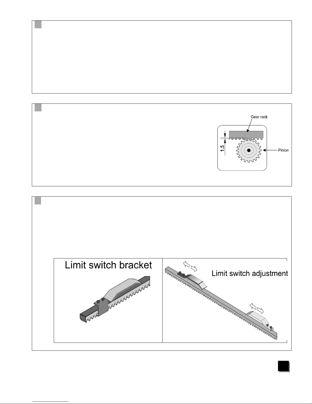
D. CHECK GEAR RACK INSTALLATION
•
Make sure that the rack is constantly in full contact with
the pinion for the full open and close travel cycle.
• After the rack has been installed it is recommended to
lower the motor position by about 1.5 mm (Fig. 5). This
is to ensure correct operation.
• Manually check if the gate reaches the mechanical
stop limits and make sure there is no friction during
gate travel.
• Do not use grease or other lubricants between rack
and pinion
Fig 5
E. LIMIT SWITCH ADJUSTMENT
• Install the limit switch brackets as shown in fig 6.
• The limit switch brackets should be initially installed at least 200mm before the end of travel
on both sides. Final adjustment should be done after successful travel learning with the
control card.
• Adjustments of the limit switch bracket should be done after all other components are
installed securely.
Fig 6
5
iS500 Series, SLIDING GATE OPENER MANUAL
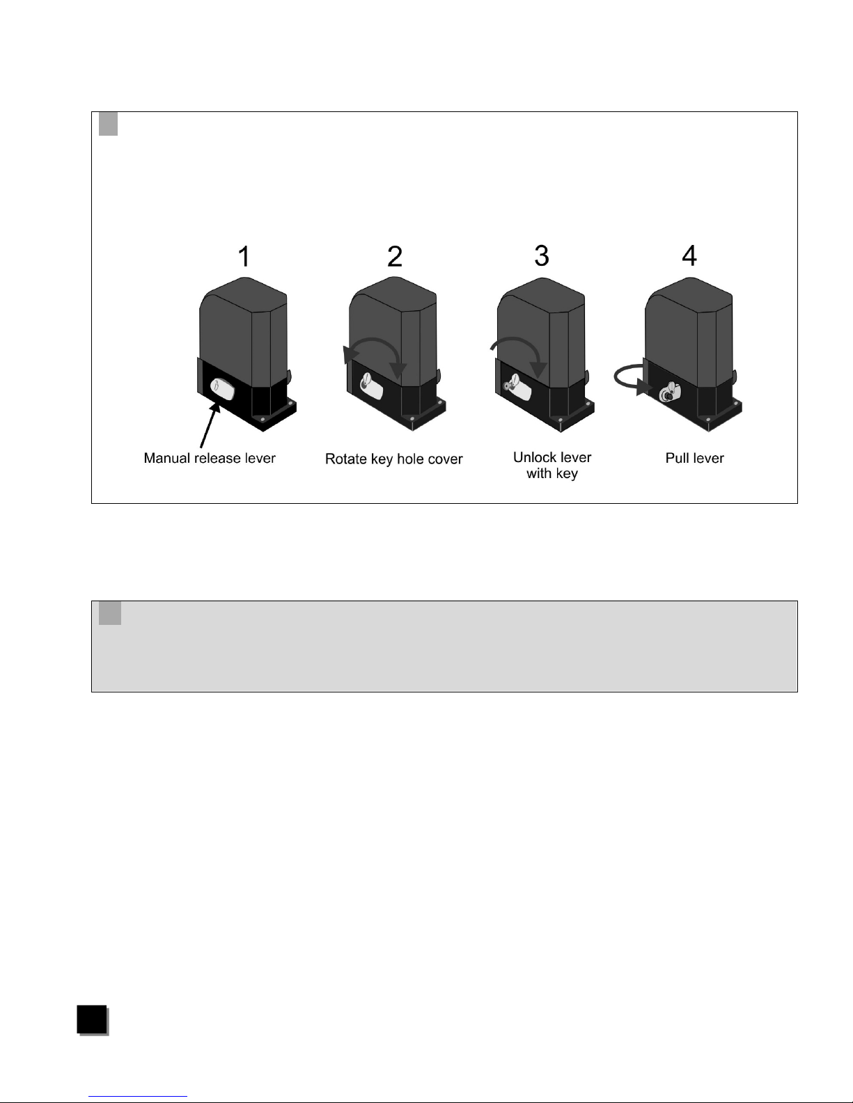
F. Manual Release
The iS500 has an unlocking mechanism. Once it’s unlocked, the gate can be operated manually in
both directions. The unlocking key is needed to unlock the motor. Please keep the key in a safe
place for later use. The manual release lever is located towards the bottom of the motor. (See
pictures below). Use the key to unlock the manual release lever. Once unlocked pull the lever so
that it’s perpendicular to the motor. The gate can now be used manually.
G. ELECTRICAL CONNECTION
After successful motor installation, refer to the user manual of the control card
for automatic operation setup.
6

iS500 Series, SLIDING GATE OPENER MANUAL
1.4 TECHNICAL FEATURES:
B Dimension:
1.5 MAINTENANCE:
Maintenance should be performed at least every six months. If it is used in high traffic area, a
more regular maintenance should be performed.
Disconnect the power supply:
(1) Clean and lubricate the screws, the wheels of the gate with grease.
(2) Check the fastening points are properly tightened.
(3) Check and make sure that the wire connections are in good condition.
Connect the power supply:
(1) Check the power adjustments.
(2) Check the function of the manual release
(3) Check the photocells or other safety device.
Motor Voltage
24Volts DC motor
Max Absorbed Power
80 Watts
Nominal Thrust
210N
Power Supply
240
Volts
AC
Nominal Input Power
2 Amps
Motor Speed
12 m/min
Maximum Gate Weight
500 kg Duty Cycle
20%
Operating Temperature
-
20°c
- +4
0°c
7

iS500 Series, SLIDING GATE OPENER MANUAL

iS500 Series, SLIDING GATE OPENER MANUAL
Service History
Date Maintenance Installer

iS500 Series, SLIDING GATE OPENER MANUAL
Swing Gate Kits
Solar Kits
Solar panels
Backup batteries
Vehicle Loop Detectors
Photo electric beams
Magnetic locks
Wireless keypads
Pre formed loop
Visit www.elsema.com to see our full range
of Gate and Door Automation products
 Loading...