


iS270/iS270D/iS270Solar SWING GATE OPENER MANUAL
iS270 / iS270D / iS270Solar
ARTICULATED ARM
GATE OPENER
USER MANUAL

iS270/iS270D/iS270Solar SWING GATE OPENER MANUAL
INDEX
1.1 GENERAL SAFETY PRECAUTION ...........................................................P.1
1.2 INSTALLATION
A. STANDARD INSTALLATION ................................................................P.2
B. INSTALLATION CHECK .......................................................................P.3
C. COMPONENTS FOR INSTALLATION..................................................P.4
D. INSTALLATION OF ARTICULATED ARM............................................P.5
E. EMERGENCY RELEASE ......................................................................P.6
F. ELECTRICAL CONNECTION ………………..........................................P.6
1.3 TECHNICAL FEATURES
A. TECHNICAL FEATURES .....................................................................P.6
B. DIMENSION ..........................................................................................P.7
1.4 MAINTENANCE ..........................................................................................P.7

iS270/iS270D/iS270Solar SWING GATE OPENER MANUAL
1.1 GENERAL PRECAUTION
WARNING:
This user manual is only for qualified technicians who are specialized in
installations and automations.
1) All installations, electrical connections, adjustments and testing must be
performed only after reading and understanding of all instructions carefully.
2) Before carrying out any installation or maintenance operation, disconnect the
electrical power supply by turning off the mains switch connected upstream
and apply the hazard area notice required by applicable regulations.
3) Make sure the existing structure is up to standard in terms of strength and
stability.
4) When necessary, connect the motorized gate to reliable earth system during
electricity connection phase.
5) Installation requires qualified personnel with mechanical and electrical skills.
6) Keep the automatic controls (remote, push buttons, key selectors. etc) placed
properly and way from children.
7) For replace or repair of motorized system, only original parts must be used.
Any damage caused by inadequate parts and methods will be not claimed to
motor manufacturer.
8) Never operate the drive if you suspect that it might be faulty or will cause
damage to the system.
9) The motors are exclusively designed for gate opening and closing application,
any other usage is deem inappropriate. The manufacturer will not be liable for
any damage resulting from the improper use. Improper usage should void all
warranty, and the user accepts sole responsibility for any risks thereby may
accrue.
10) The system may be operated in proper working order. Always follow the
standard procedures by following the instructions in this installation and
operating manual.
11) Only operate the remote when you have the full view of the gate.
ELSEMA PTY LTD shall not be liable for any injury, damage, or any claim to
any person or property which may result from improper use or installation
of this system.
Please keep this installation manual for future reference.
1

iS270/iS270D/iS270Solar SWING GATE OPENER MANUAL
1.2 STANDARD INSTALLATION
A. STANDARD INSTALLATION
2

iS270/iS270D/iS270Solar SWING GATE OPENER MANUAL
B. CHECKS BEFORE INSTALLATION
Before proceeding with the installation check the following:
1) Be sure that gate moves freely.
2) There are no obstacles in the moving gate area.
3) Hinges are properly positioned and greased.
4) There should be no friction between the two gate leafs.
5) There should be no friction with the ground while moving the gates.
6) Check that the gate structure is suitable to install automatic gate motors.
Follow
the measures shown in the chart for proper installation. If necessary, please adjust the
gate structure for optimum performance.
3

iS270/iS270D/iS270Solar SWING GATE OPENER MANUAL
C. COMPONENTS FOR INSTALLATION
D. INSTALLATION OF ARTICULATED ARM
• Refer to the Dimension Chart to choose the correct dimensions of the motors and position to be
installed.
• Check if the mounting surface where the brackets are to be installed is smooth, vertical and rigid.
• Run the cables for power supply and cable for the motors.
• Motor installation and setting for mechanical stopper in opened and closed position.
1. Remove the upper cover and mechanical
stoppers from the bottom of the motor.
2. Place the gate in the full closed position and fix
the U-shaped fixing plate on the wall.
4

iS270/iS270D/iS270Solar SWING GATE OPENER MANUAL
3. Install the motor on the U-shaped fixing plate
with corresponding screws and nuts.
4. After positioning the front of the curved arm on the
bottom of the motor, release the motor and position
the minor arm on the end of curved arm and the
mounting bracket with corresponding screws and nuts.
5. Fully closed position adjustment :
5.1 Fix the mechanical stopper at the fully closed position.
5.2 Move the gate manually to the fully closed position.
5.2 Align the pointer on the limit switch to the pointer on the curved arm.
(Red points shown on the figure below indicate the pointers)
6. Fully open position adjustment :
6.1 Fix the mechanical stopper at the fully open position.
6.2 Move the gate manually to the fully open position.
6.2 Align the pointer on the limit switch to the pointer on the curved arm.
(Red points shown on the figure below indicate the pointers)
5

iS270/iS270D/iS270Solar SWING GATE OPENER MANUAL
E. EMERGENCY RELEASE
In case of power failure, The operator can be switched to manual operation.
1) Insert the release key to the release slot
2) Turn the release key anti-clockwise
3) Pull out the release bar
4) Turn the release key clockwise to fix the release bar, the release bar has to be in pulled out
position when turning the release key clockwise.
J. ELECTRICAL CONNECTION
After successful motor installation, refer to the user manual of the control card
for automatic operation setup.
1.3 TECHNICAL FEATURES:
A. Technical Features:
Motor Voltage
24Volts DC motor
Gear Type
Worm gear
Nominal Thrust
12
00N Power Supply
240
Volts
AC
Nominal Input Power
2 Amps
Maximum Gate Weight
25
0 kg per leaf
Maximum Gate Length
2.5 metres
Duty Cycle
20%
Operating Temperature
-
20°c ~ +50°c
Dimension
256
mm x
267
mm x
187mm Weight
6 kg
6
iS270/iS270D/iS270Solar SWING GATE OPENER MANUAL
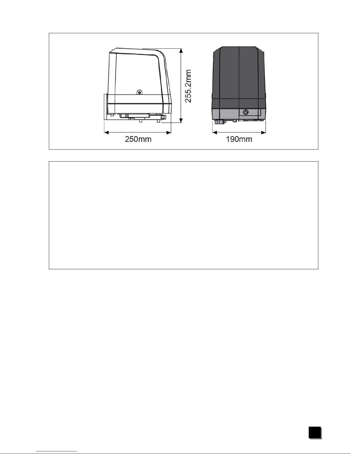
B Dimension:
1.4 MAINTENANCE:
Maintenance should be performed at least every six months. If it is used in high traffic area, a
more regular maintenance should be performed.
Disconnect the power supply:
(1) Clean and lubricate the screws, the pins and the hinge with grease.
(2) Check the fastening points are properly tightened.
(3) Check and make sure that the wire connections are in good condition.
Connect the power supply:
(1) Check the power adjustments.
(2) Check the function of the manual release
(3) Check the photocells or other safety device.
7

iS270/iS270D/iS270Solar SWING GATE OPENER MANUAL
Service History
Date Maintenance Installer
8

iS270/iS270D/iS270Solar SWING GATE OPENER MANUAL
Solar kits
Solar panels
Backup batteries
Photo electric beams
Magnetic locks
Wireless keypads
Pre formed loop
Visit www.elsema.com to see our full range
of Gate and Door Automation products
 Loading...