

Page 1

AirLancerTM MC-II
TM
AirLancer
AirLancer
USB-II
TM
PCI-II
Page 2

© 2001
While the information in this manual has been compiled with great care, it may not be deemed an assurance of product
characteristics.
The reprodu cti on and di stribut ion o f th e doc umentat ion an d soft war e suppl ied w ith this product and t he use of it s conten ts
is subject to written authorization from LANCOM Systems.
Trademarks
®
Windows
, Windows NT® and Microsoft® are registered tr ademarks of Microsof t, Corp.
Subject to c hange without notice. No liability f or tec hnical errors or omis sions.
March 2001
110046
Page 3

Preface
|
Thank you for placing your trust in this product.
Wireless networks are economical alternatives or additions to
local wired networks (LANs). Notebooks and PCs can use mobile network
cards to communicate with one another or access wired networks via access
points and can even be integrated into the ISDN network.
This documentation is intended for the user of theAirLancer MC-11,
AirLancer USB-11 and AirLancer PCI-11 mobile network cards.
First we describe the devices and their options, then provide instructions for
installing the devices and the drivers and as an initial application example we
descr ibe how to co nnect t wo c omputer s wit h each other and to an ac cess
point.
Documentation
This do cumentat ion was com piled by seve ral memb ers of our st aff from a
variety of departments in order to ensure you the best possible support when
using your product.
EN
Our online services are available to you around the clock
should you have any queries regarding the topics discussed in this manual or
require any further support.
AirLancer
|
|
Page 4

EN
|
AirLancer
|
|
Page 5

|
Contents
1 Introduction . . . . . . . . . . . . . . . . . . . . . . . . . . . . . . . . . . . . . . . . . . . . . . . . . . . . . . . . . . . . . . . 9
1.1 What is a wireless LAN? . . . . . . . . . . . . . . . . . . . . . . . . . . . . . . . . . . . . . . . . . . . . . . 9
1.2 What is required for a wireless LAN? . . . . . . . . . . . . . . . . . . . . . . . . . . . . . . . . . . . . 9
1.2.1 Radio interfaces with the network . . . . . . . . . . . . . . . . . . . . . . . . . . . . . . . . . . 9
1.2.2 The center—the access point . . . . . . . . . . . . . . . . . . . . . . . . . . . . . . . . . . . . 10
1.3 Operating modes . . . . . . . . . . . . . . . . . . . . . . . . . . . . . . . . . . . . . . . . . . . . . . . . . . . 10
1.3.1 The ad hoc network. . . . . . . . . . . . . . . . . . . . . . . . . . . . . . . . . . . . . . . . . . . . . 10
1.3.2 The infrastructure network . . . . . . . . . . . . . . . . . . . . . . . . . . . . . . . . . . . . . . . 10
1.4 IEEE 802.11b radio transmission . . . . . . . . . . . . . . . . . . . . . . . . . . . . . . . . . . . . . . . 11
1.5 The three AirLancers . . . . . . . . . . . . . . . . . . . . . . . . . . . . . . . . . . . . . . . . . . . . . . . . 12
1.5.1 Matching versions for international use. . . . . . . . . . . . . . . . . . . . . . . . . . . . . 12
1.5.2 Encryption in two levels of security . . . . . . . . . . . . . . . . . . . . . . . . . . . . . . . . 13
1.6 What now?. . . . . . . . . . . . . . . . . . . . . . . . . . . . . . . . . . . . . . . . . . . . . . . . . . . . . . . . 13
EN
2 AirLancer MC-11 . . . . . . . . . . . . . . . . . . . . . . . . . . . . . . . . . . . . . . . . . . . . . . . . . . . . 15
2.1 Package contents . . . . . . . . . . . . . . . . . . . . . . . . . . . . . . . . . . . . . . . . . . . . . . . . . . . 15
2.2 The card . . . . . . . . . . . . . . . . . . . . . . . . . . . . . . . . . . . . . . . . . . . . . . . . . . . . . . . . . . 15
2.3 Installation . . . . . . . . . . . . . . . . . . . . . . . . . . . . . . . . . . . . . . . . . . . . . . . . . . . . . . . . 16
2.3.1 Checking the system requirements. . . . . . . . . . . . . . . . . . . . . . . . . . . . . . . . . 16
2.3.2 Inserting the card in the computer . . . . . . . . . . . . . . . . . . . . . . . . . . . . . . . . . 17
2.3.3 Driver installation under Windows 98 and Windows 95 . . . . . . . . . . . . . . . . 18
2.3.4 Installation of the drivers under Windows Me. . . . . . . . . . . . . . . . . . . . . . . . 19
2.3.5 Installation of the drivers under Windows 2000 . . . . . . . . . . . . . . . . . . . . . . 19
2.3.6 Installation of the drivers under Windows NT 4.0 . . . . . . . . . . . . . . . . . . . . . 20
2.3.7 Installation of the drivers under Windows CE . . . . . . . . . . . . . . . . . . . . . . . . 20
2.3.8 Installation of the drivers under Linux . . . . . . . . . . . . . . . . . . . . . . . . . . . . . . 21
3 AirLancer USB-11 . . . . . . . . . . . . . . . . . . . . . . . . . . . . . . . . . . . . . . . . . . . . . . . . . . . 23
3.1 Package contents . . . . . . . . . . . . . . . . . . . . . . . . . . . . . . . . . . . . . . . . . . . . . . . . . . . 23
3.2 The adapter. . . . . . . . . . . . . . . . . . . . . . . . . . . . . . . . . . . . . . . . . . . . . . . . . . . . . . . . 23
3.3 Installation . . . . . . . . . . . . . . . . . . . . . . . . . . . . . . . . . . . . . . . . . . . . . . . . . . . . . . . . 24
3.3.1 Checking the system requirements. . . . . . . . . . . . . . . . . . . . . . . . . . . . . . . . . 24
3.3.2 Connecting the adapter to your PC. . . . . . . . . . . . . . . . . . . . . . . . . . . . . . . . . 24
3.3.3 Installation of the drivers under Windows 98 . . . . . . . . . . . . . . . . . . . . . . . . 25
3.3.4 Installation of the drivers under Windows Me. . . . . . . . . . . . . . . . . . . . . . . . 26
3.3.5 Installation of the drivers under Windows 2000 . . . . . . . . . . . . . . . . . . . . . . 26
AirLancer
|
|
Page 6

|
4 AirLancer PCI-11 . . . . . . . . . . . . . . . . . . . . . . . . . . . . . . . . . . . . . . . . . . . . . . . . . . . . 29
4.1 Package contents . . . . . . . . . . . . . . . . . . . . . . . . . . . . . . . . . . . . . . . . . . . . . . . . . . . 29
EN
5 The AirLancer Client Manager . . . . . . . . . . . . . . . . . . . . . . . . . . . . . . . . . . . . . . . . . . . . . 37
4.2 The adapter. . . . . . . . . . . . . . . . . . . . . . . . . . . . . . . . . . . . . . . . . . . . . . . . . . . . . . . . 29
4.3 Installation . . . . . . . . . . . . . . . . . . . . . . . . . . . . . . . . . . . . . . . . . . . . . . . . . . . . . . . . 30
4.3.1 Checking the system requirements. . . . . . . . . . . . . . . . . . . . . . . . . . . . . . . . . 30
4.3.2 Installing the AirLancer PCI-11 . . . . . . . . . . . . . . . . . . . . . . . . . . . . . . . 31
4.3.3 Inserting the AirLancer MC-11 . . . . . . . . . . . . . . . . . . . . . . . . . . . . . . . 32
4.3.4 Installation of the drivers under Windows 98 . . . . . . . . . . . . . . . . . . . . . . . . 32
4.3.5 Installation of the drivers under Windows Me. . . . . . . . . . . . . . . . . . . . . . . . 33
4.3.6 Installation of the drivers under Windows 2000 . . . . . . . . . . . . . . . . . . . . . . 33
4.3.7 Installation of the drivers under Windows NT 4.0 . . . . . . . . . . . . . . . . . . . . . 34
4.3.8 Installation of the drivers under Linux . . . . . . . . . . . . . . . . . . . . . . . . . . . . . . 35
5.1 Installation . . . . . . . . . . . . . . . . . . . . . . . . . . . . . . . . . . . . . . . . . . . . . . . . . . . . . . . . 37
5.2 Basic configuration. . . . . . . . . . . . . . . . . . . . . . . . . . . . . . . . . . . . . . . . . . . . . . . . . . 37
5.3 Overview of functions. . . . . . . . . . . . . . . . . . . . . . . . . . . . . . . . . . . . . . . . . . . . . . . . 38
5.3.1 Administration of profiles. . . . . . . . . . . . . . . . . . . . . . . . . . . . . . . . . . . . . . . . 38
5.3.2 Configuration. . . . . . . . . . . . . . . . . . . . . . . . . . . . . . . . . . . . . . . . . . . . . . . . . . 38
5.3.3 Analysis, diagnostics and information . . . . . . . . . . . . . . . . . . . . . . . . . . . . . . 39
5.3.4 Further information . . . . . . . . . . . . . . . . . . . . . . . . . . . . . . . . . . . . . . . . . . . . . 39
5.4 Encryption settings. . . . . . . . . . . . . . . . . . . . . . . . . . . . . . . . . . . . . . . . . . . . . . . . . . 39
5.4.1 General rules for WEP keys . . . . . . . . . . . . . . . . . . . . . . . . . . . . . . . . . . . . . . 39
5.4.2 Valid key characters . . . . . . . . . . . . . . . . . . . . . . . . . . . . . . . . . . . . . . . . . . . . 40
5.4.3 Continuous change of key. . . . . . . . . . . . . . . . . . . . . . . . . . . . . . . . . . . . . . . . 40
6 Example configurations . . . . . . . . . . . . . . . . . . . . . . . . . . . . . . . . . . . . . . . . . . . . . . . . . . . 41
6.1 Direct PC connection . . . . . . . . . . . . . . . . . . . . . . . . . . . . . . . . . . . . . . . . . . . . . . . . 41
6.2 Link to a company network. . . . . . . . . . . . . . . . . . . . . . . . . . . . . . . . . . . . . . . . . . . . 44
7 AirLancer Extender . . . . . . . . . . . . . . . . . . . . . . . . . . . . . . . . . . . . . . . . . . . . . . . . . . 47
8 Security in the wireless LAN . . . . . . . . . . . . . . . . . . . . . . . . . . . . . . . . . . . . . . . . . . . . . . . 49
8.1 Closed network. . . . . . . . . . . . . . . . . . . . . . . . . . . . . . . . . . . . . . . . . . . . . . . . . . . . . 49
8.2 Access control via MAC address . . . . . . . . . . . . . . . . . . . . . . . . . . . . . . . . . . . . . . . 49
8.3 Encryption of the data transfer (WEP) . . . . . . . . . . . . . . . . . . . . . . . . . . . . . . . . . . . 50
8.3.1 How WEP works . . . . . . . . . . . . . . . . . . . . . . . . . . . . . . . . . . . . . . . . . . . . . . . 50
8.3.2 Notes for the correct use of keys . . . . . . . . . . . . . . . . . . . . . . . . . . . . . . . . . . 50
8.3.3 Further security improvements . . . . . . . . . . . . . . . . . . . . . . . . . . . . . . . . . . . . 51
AirLancer
|
|
Page 7

|
9 Appendix . . . . . . . . . . . . . . . . . . . . . . . . . . . . . . . . . . . . . . . . . . . . . . . . . . . . . . . . . . . . . . . . 53
9.1 Technical data . . . . . . . . . . . . . . . . . . . . . . . . . . . . . . . . . . . . . . . . . . . . . . . . . . . . . 53
9.2 Radio channels . . . . . . . . . . . . . . . . . . . . . . . . . . . . . . . . . . . . . . . . . . . . . . . . . . . . . 54
9.3 Restrictions for use within EU countries . . . . . . . . . . . . . . . . . . . . . . . . . . . . . . . . . 54
9.4 Declarations of conformity. . . . . . . . . . . . . . . . . . . . . . . . . . . . . . . . . . . . . . . . . . . . 55
9.4.1 European Union (CE) . . . . . . . . . . . . . . . . . . . . . . . . . . . . . . . . . . . . . . . . . . . . 55
9.4.2 Federal Communications Commission (FCC). . . . . . . . . . . . . . . . . . . . . . . . . . 55
9.5 Warranty conditions. . . . . . . . . . . . . . . . . . . . . . . . . . . . . . . . . . . . . . . . . . . . . . . . . 58
EN
AirLancer
|
|
Page 8

EN
|
AirLancer
|
|
Page 9

1 Introduction
Introduction
|
9
The advantages of wireless networks (wireless LANs) are obvious:
Notebo oks and PCs can be set up where they are wanted. Prob lems with
miss ing po rt s or co ns tr uct io n a lte ra ti on s ar e a th in g of the pa st wi th wi re les s
networking.
Network links in conferences or presentations, access to resources in
adjac ent bu ilding s and exch an ging data wi th mob ile uni ts are on ly a few of
the options available with a wireless LAN.
1.1 What is a wireless LAN?
Wirel ess L ANs c onne ct sepa rate unit s (P Cs and note books ) to a l ocal networ k
(also LAN – Local Area Network). Unlike conventional LANs, the connection
is estab lished th rough r adio tra nsmis sion, not v ia a netw ork cable . For th is
reason, wireless LANs are also called Wireless Local Area Networks
(WLAN).
All of the standard functions of a wired network are also available in a
wireless LAN: Access to files, servers, printers etc. is possible as is the
integration of the single stations into an internal company e-mail system or
access to the Internet .
EN
1.2 What is required for a wireless LAN?
The question of the required hardware arises in conjunction with the
advantages of a wireless LAN.
1.2.1 Radio interfaces with the network
Every unit in the wireless LAN needs access to the wireless LAN in the form
of a radio interface. Devices that do not come with a standard radio interface,
can be upgraded using an advanced card or an adapter. You use an
AirLancer to upgrade your unit to access the wireless LAN.
A wi rel es s L AN c ons i sts o f at le as t tw o uni ts w ith ra di o in te rfa ces . B ot h un it s
then communicate directly via radio.
AirLancer
|
|
Page 10
Introduction
10
|
1.2.2 The center—the access point
EN
The c on ven ie nc e a nd pe r fo rm an ce of a w ir el ess LAN ca n en hanced w ith an
additional access poin t. Thi s access point permits the central administration
of the wireless LAN. In addition, the acces s point ca n be us ed to link the
wireless LAN to a cable-based LAN or to the Internet.
Depending on whether or not an access point is used, there are two possible
ways to op erat e the w irele ss LA N: Eit her a s an ad ho c netwo rk ( peer- to-p eer),
or an infrastructure network (access point).
1.3 Operating modes
Let's have a look at both operating modes.
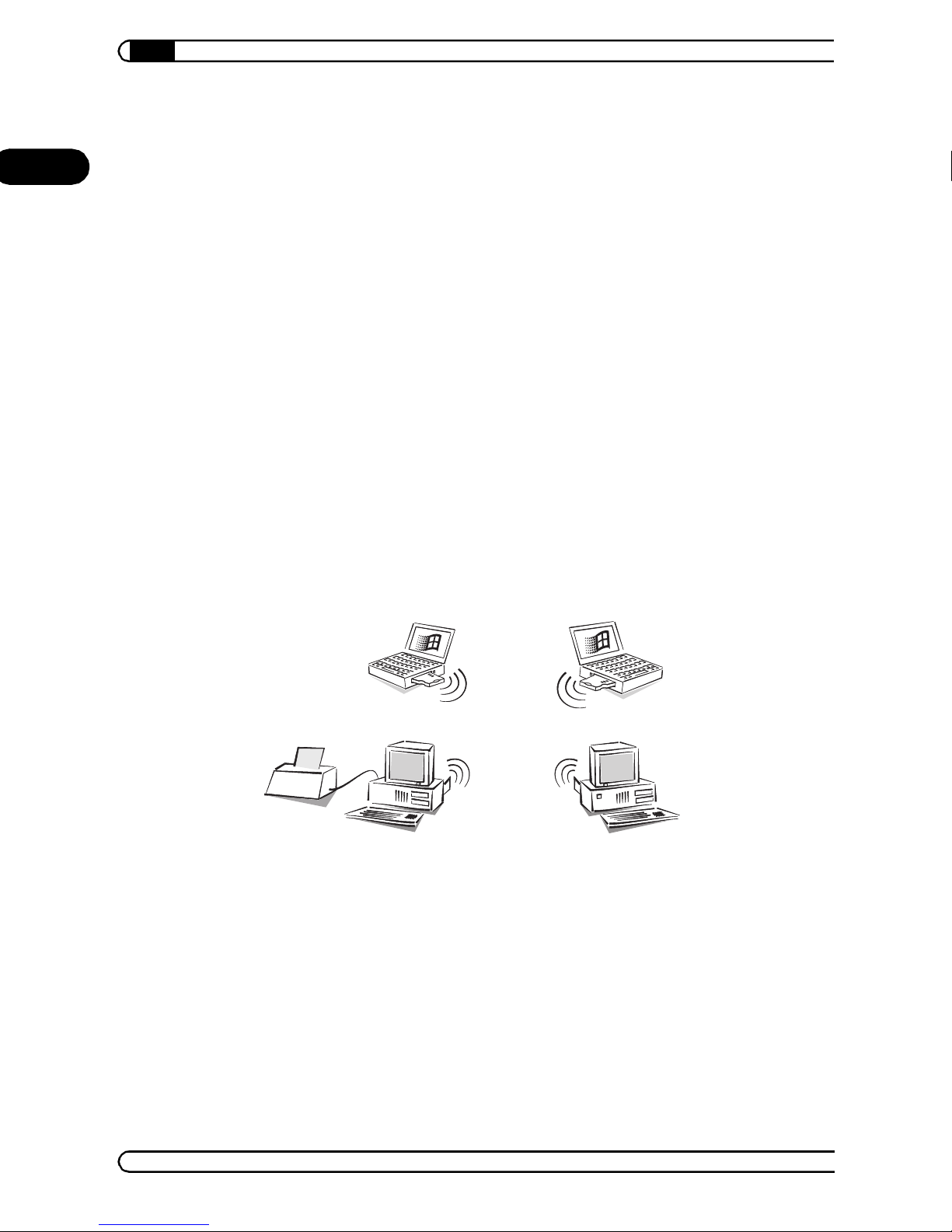
1.3.1 The ad hoc network
In th e case of th e ad h oc netw ork, two o r more comput ers that e ach ha ve t heir
own interfaces to the wireless LAN are connected to one another. All
computers in a WLAN can then communicate with one another with no
additional hardware.
Ad hoc network
This mode is also generally referred to as a peer-to-peer network
(spontaneous network). PCs can connect to each other immediately and
exchange data.
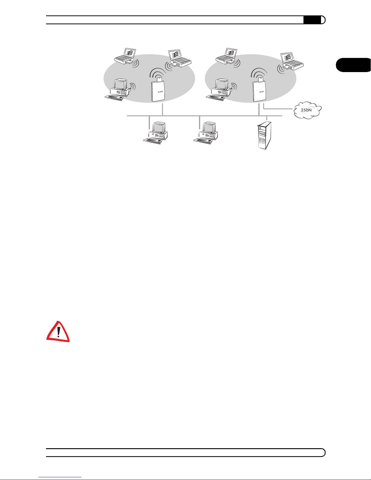
1.3.2 The infrastructure network
An access point is required to connect to an existing network. The access
poin t acts as the swi tchi ng cen ter fo r data ex change withi n the WL AN. It a lso
offers access to a cable-based LAN or to the ISDN and Internet.
AirLancer
|
Ad hoc net w or k
Page 11
Introduction
|
11
EN
Infrastructure
network
A wireless LAN with one o r more acce ss p oint s is gen erall y ref erre d to a s a
peer-to-LAN network; however, in the LAN terminology this type of
networking is referred to as an infrastructure network. access points
also have an integrated router for ISDN or DSL connections. This allows all
connected stations to access the Internet.
This network type is ideally suited as an addition to existing LANs. The
infrastructure network is the ideal solution for expansion of a LAN in areas
whe re wiring is not pos sible or not economical.
1.4 IEEE 802.11b radio transmission
IEEE 802.11b
All AirLancer operate under IEEE Standard 802.11b. This standard is a
supplement to the current IEEE standards for LANs, with IEEE 802.3 for
Ethern et being the mo st well-k nown. IEE E 802.11b cover s the oper ation of
local wireless LANs on private and public property in the ISM frequency
range (Industrial, Scientific, Medical: 2.4 and 2.483 GHz).
Please note that not all frequencies are permitted in every country! A table
wit h the freq uenci es an d the appr ova l reg ulati ons i s inc lud ed in the app endi x.
11 Mbps
The max imu m band widt h for data tra nsf er is 11 Mbps . Howe ver, th e actu al
throug hp ut dep ends on both the dis ta nce and the qu ali ty of th e conn ecti on.
Increasing distance and decreasing connection quality reduces the transfer
speed to 5.5 Mbps, th en to 2 and fi nally 1 Mb ps. The transfer range in th e
open is up to 400 meters, in buildings it is typically around 30 – 40 meters.
The actual range achieved strongly depends on the spatial environment.
Interference and obstacles in particular have a strong influence on the range.
Optimum posi tioni ng of the wireless stations is often decisive.
AirLancer
|
|
Page 12

12
Introduction
|
DSSS
EN
The wireless LAN cards from use the DSSS process (Direct Sequence
Spread Spectrum) to shield against interference from other transmitters that
may be using the same frequency range. A transmitter normally uses only a
very narrow range of the available frequency band for transfer. If precisely
this range is a lso in use by anot her tra nsmi tter, this w ill cause interf erence
in the tra ns f er . In t he DSS S pro c ess th e tr an smit te r us e s a br oa de r s ecti o n of
the possible frequency band and so is less sensitive to narrow-band
interference. This process is also used by the military to make eavesdropping
more difficult.
1.5 The three AirLancers
The AirLancer series offers you three models. This way, you can obtain
acc ess to the wirele ss LA N with con venti onal PCs and a v ari ety of note book s:
AirLancer MC-11
PC card (according to PCMCIA standard) for notebooks
AirLancer USB-11
Wireless LAN adapter for the li nk to a USB interface
AirLancer PCI-11
PCI adapter for the installation of an AirLancer MC-11 in a PC. An
AirLancer MC-11 card is delivered with the product.
1.5.1 Matching versions for international use
In the ISM range, up to 13 radio channels can be used. Some countries have
only released 11 out of 13 channels for public use. This is why there are two
versions of every wireless LAN adapter:
The E U ver si o n c an be us e d in t he en ti re E U an d i n m os t of th e as s oci at ed
European co untrie s. The c ar d supports 1 3 ra dio cha n n els an d m eets th e
European CE standard.
AirLancer
|
|
Page 13

The WORLD version is meant for use in Europe and other countries,
especially the USA. Apart from the European CE standard, it also meets
the American FCC standard. The maximum number of channels is 11.
Accessing an EU access point with an AirLancer WORLD version
In order to be able to access an EU access point (supports 13 radio channels)
with an AirLancer WORLD v er s ion (o nl y su pp ort s 11 ra di o c ha nn el s) , yo u mus t
choose a channel between 1 and 11 on the access point.
For guidance regarding the manual setting of channels please refer to the
documentation of your access point. A list of the radio channels that are supported by th e t w o ve rs ion s is ava ila ble in pa r ag ra ph 9.2 'R a dio ch an nels' on
page 54.
1.5.2 Encryption in two levels of security
Introduction
|
13
EN
Some countries regulate the use of encryption technology. This is why there
are two versions of every AirLancer wireless LAN adapter:
WEP64—for the encryption according to Wired Equivalent Privacy (WEP)
keys are used wit h an effective length of 40 bits.
WEP128—th is model versio n uses keys with a lengt h of 104 bits. Th e
encryption attained is considerably stronger, compared to the models
using WEP64.
Please inform yourself on the current legal regulations for the use of
encryption technology in the country where you want to use an A
AirLancer. Make sure not to use devic e s that support illegal encryption's
techniques.
Detailed informatio n on the use of WEP encryption can be found in chapter 8
'Security in the wireless LAN' on page 49.
1.6 What now?
The following three chapters will give you detailed descriptions and
installation instructions for each of the three AirLancer. Every chapter covers
one product. Just move s traight on t o the chapter for your product. Don't
worry about skipping the other chapters.
The section of the documentation from chapter 5 onwards once again applies
to all AirLancer network cards.
AirLancer
|
|
Page 14

EN
14
Introduction
|
AirLancer
|
|
Page 15
2 AirLancer MC-11
|
AirLancer MC-11
15
This chapter describes the AirLancer MC-11 and a step-by-step
instruction for the installation of the card. After successfully setting up
hardware, drivers and software, we are left with setting up access to a
wireless LAN. This configuration is described for all AirLancer in chapter 5.
2.1 Package contents
Please ensure first that the delivery is complete. The package should include
the following components:
AirLancer MC-11
AirLancer CD including drivers, AirLancer Client Manager and electronic
documentation
User Manual
If anything should be missing, plea se cont act your dealer.
2.2 The card
EN
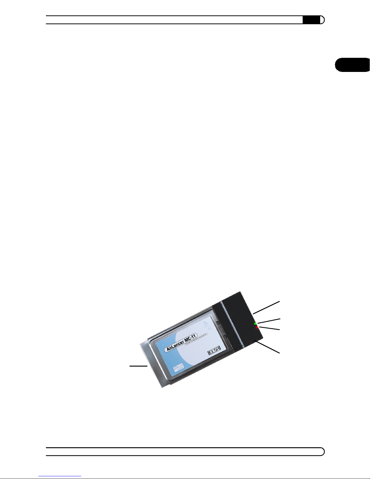
The wireless network card AirLancer MC-11 is a PC card for notebooks
and mobile computers with PC card interfaces according to the PCMCIA
standard. It is slightly longer than other PC cards. The internal radio antenna
of the AirLancer MC-11 is located in the protruding part of the card.
PCMCIA slot
Connector for optional external antenna
LED for the operating mode of the card:
AirLancer
|
|
Page 16

AirLancer MC-11
16
Lit green – standard mode
Bli nking green – the card is in energy-saving mode
EN
LED for the transmission and receiving mode:
Off – no wireless activity
Blinking – wireless data being sent or received
Integrated antenna
2.3 Installation
The installation of the AirLancer MC-11 takes place in four steps:
햲 Checking the system requirements
햳 Plugging in the AirLancer MC-11 into your PC
햴 Installation of the drivers
|
햵 Sett ings fo r the acc ess to th e wirele ss LAN—you wi ll fi nd the in stru ction
for this configuration in chapter 5 'The AirLancer Client Manager' on
page 37.
2.3.1 Checking the system requirements
Before starting the installation process, you should check if your computer
fulfills all syste m require m ents:
Your P C o r handh el d /poc ket PC m ust h av e at least one vacan t PC car d
slot (PCMCIA, type II or type III)
CD ROM driv e (or , in case of Wi nd ows C E: an Ac tiveS yn c con ne ct or to a
PC with CD ROM drive and Windows operating system).
One of the following operating s ystems:
Windows 98, Windows 95
Windows Millennium Edition (Me)
Windows 2000
Windows NT 4.0
Windows CE 2.11/2.12 or Windows CE 3.0
Linux
AirLancer
|
|
Page 17

|
Secure power supply
If during the installation, the firmware of your AirLancer MC-11
tur ns out not to be up to date, the setup pr ogram wil l suggest to you the
autom atic updati ng of the fi rmware . Thi s acti on ne eds yo ur con firma tio n.
Please ensure before beginning with the updating of the firmware that a
stabile power supply is guaranteed during the installation. Avoid carrying
out the installation on a notebook running on its battery. Please also
ensure that your computer does not shut down or go into standby during
the updati ng process. Close all applications before starting.
Additional system requirements for Windows NT 4.0
For the installation under Windows NT 4.0 please ensure that the
required system resources are available before placing the card into your
computer. The procedure is as follows:
The AirLancer MC-11 will be installed with IRQ 10 and the address
range '400–437' by default. The interrupts and addresses can be viewed
under Start Programs Administrative Tools (Common)
Windows NT Diagnostics.
AirLancer MC-11
17
EN
If the re quire d reso urc es ar e not availa ble, pl eas e make a not e of othe r
fre e r esou rc e s an d s pe cif y th em d ur i ng the i ns t al lat io n. I t i s al s o po ssi ble
to cha nge t he re sour c e all oc ati on s at a la te r t im e with Start Settings
Control Panel Network Adapters Properties.
Additional system requirements for Windows CE
The drivers for Windows CE require a firmware status of 6.06 or higher
for AirLancer MC-11. Older cards may require updating of the
firmw are. T his upd ating tak es place auto mati cal ly if you fi rst insta ll the
card in a computer under Windows 98, Windows 95, Windows Me or
Windows 2000.
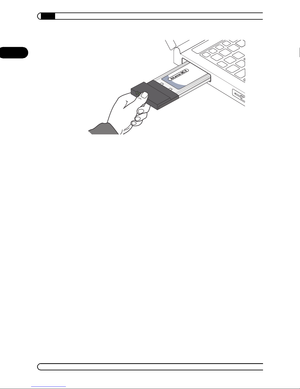
2.3.2 Inserting the card in the computer
Insert the card into a free PC c ard slot of your enabled computer. Please
ensure that the side with the produc t name faces up, wh ile th e side with t he
serial number faces downwa rds.
AirLancer
|
|
Page 18
EN
AirLancer MC-11
18
|
The operating systems Windows 98, Windows 95, Windows 2000 and
Wind ows Me will ge ne rate a mess age on th e scre en s hort ly aft er inse rtin g
the card, announcing the detection of the new hardware.
The ins tall ation of th e req uire d driv er dif fers for v ariou s ope ratin g s ystem s.
The foll owing se ctions describ e the inst allatio n proced ure for yo ur spec ific
operating system.
2.3.3 Driver installation under Windows 98 and Windows 95
햲 Please confirm the 'Add New Hardware Wizard' window with Next,
select the option Search for the best driver for your device from the
list and click Next.
햳 Enable th e option Specify a location in th e follo wing d ialog windo w
and dis able al l othe r optio ns . Insert the AirLancer CD into the CD-ROM
drive (e. g. 'D:\').
햴 Use Browse... to switch to the folder containing the driver for your
operating system (in which 'D:' is always the drive letter of your CD-ROM
drive):
Windows 95: 'D:\driver\Win95\.. '
Window s 98: 'D:\driver\Win98\..
햵 Confirm with Next, to start copying.
햶 Click Finish to ex it ins talla ti on.
AirLancer
|
Page 19

|
On the screen the window 'Add/Edit Configuration Profile' opens. This is
where you will later configure the access to your wireless LAN. Now please
move on to chapter 5 'Th e AirLancer Client Manager' on page37, in order to
change these settings .
AirLancer MC-11
2.3.4 Installation of the drivers under Windows Me
햲 Af ter star ting the 'Ad d New Hardw are Wi zard', selec t the o ption Specify
the location of the driver and click Next.
햳 In the following dialog window, select Search for the best driver for
your device (Recommended).
햴 Disable the option Removable Media (Floppy, CD-ROM...).
햵 Please select the Specify a location option .
햶 Insert the AirLancer CD in your CD- ROM dr ive (e .g. ' D:\' ), u se the Browse
option to switch to the folder 'D:\driver\Winme\ (in which 'D:' is
the drive letter of your CD-ROM drive) an d clic k Next.
19
EN
햷 Confirm the display of the search results by clicking Next. When the
wizard is ready, click Finish to end the instal lation.
On the screen, the window 'Add/Edit Configuration Profil e' opens. This is
where you will later configure the access to your wireless LAN. Now please
move on to chapter 5 'Th e AirLancer Client Manager' on page37, in order to
change these settings .
2.3.5 Installation of the drivers under Windows 2000
햲 Confirm the 'Found New Hardware Wizard' dialog window with Next.
햳 Select the Search for a s uitabl e dri ver for my dev ice option a nd c lic k
Next.
햴 In the 'L ocate Drive r Files' d ialog, se lect Specify a location and click
Next.
햵 Insert the AirLancer CD in your CD-ROM drive (e. g. 'D:') use the
Browse... option to switch to the folder 'D:\driver\Win2k\' (in
which ' D : ' is the drive letter of your CD-ROM drive) and confirm with OK.
햶 Confirm the display of the search results by clicking Next.
AirLancer
|
|
Page 20

AirLancer MC-11
20
햷 Window s 2 00 0 then in sta lls the dr ive r. W hen the w izar d is re ad y, press
Finish.
EN
On the screen the 'Add/Edit Configuration Profile' window opens. This is
where you will later configure the access to your wireless LAN. Now please
move on to chapter 5 'Th e AirLancer Client Manager' on page37, in order to
change these settings .
|
2.3.6 Installation of the drivers under Windows NT 4.0
햲 Start the installation with Start Settings Control Panel
Network. Select the 'Network Adapter' register tab and click the Add
button.
햳 In the 'Select Network Adapter' window please select the button Have
Disk..., and then enter the following path for the driver data on the
AirLancer CD: 'D:\driver\windows\win_nt' (in which 'D:' is the drive letter of
your CD-ROM drive). Accept the following prompts to log AirLancer
MC-11 as a net w or k ca rd .
햴 Fi nish the installation and restart your computer.
In the next step you w ill confi gure the access to your wire less LAN . Please
move on to chapter 5 'The AirL ancer Cl ient Manager' on page37, where you
will find the descript ion of the required setting s.
2.3.7 Installation of the drivers under Windows CE
Updated and additional information on the Windows CE driver and the
supported devices can be found in the 'README.TXT' in the folder in the
folder '\d ri v er\Wince' on the A ir Lan cer CD.
햲 Connect your Windows CE computer to a Windows PC that has a
CD-ROM drive at its disposal. Start up both computers and establish an
ActiveSync connection.
햳 Place the AirLancer CD in your CD-ROM drive. The setup program will
start automatically. If the CD does not start automatically, please start
'AUTORUN.EXE' from the root folder on the CD.
햴 Select Windows CE driver from the setup main menu.
햵 From the following menu, select the Windows CE version of your mobile
device.
AirLancer
|
|
Page 21

|
햶 The setup program will then start. Please follow the instructions. The
drivers are installed on the Windows CE computer via the synchronization
connection.
In the next step you will configure access to your wireless LAN. Now please
move on to chapter 5 'The AirL ancer Cl ient Manager' on page37, where you
will find the descript ion of the required setting s.
2.3.8 Installation of the drivers under Linux
It is not necessary to recompile the kernel in the current Linux distributions.
The PC MC IA comp onent s a re i nc lu de d as m od ules. This short de scr ip tion is
based on SuSE version 7.0.
AirLancer MC-11
21
EN
The adap tat ion s requ ired to th e par amet ers in the f ile
will b e made au to mat i cal ly du ri ng i nst al l atio n of th e PCM CIA p ack et wi th t he
aid of YaST.
To continue setting up the card the file
AirLancer.conf
/etc/pcmcia.
Then the card will log on to the fi rst acc ess point that it f inds.
In order to configure a fixed network name, the following line must be
commented out in the file
module "wavelan2_cs" opts "network_name=MyNetwork"
MyNetwork
See the file Readme.txt on the AirLancer CD for additional settings options.
must be replaced by the netw ork name s.
on the AirLancer CD m ust be co pied to the dir ectory
/etc/pcmcia/AirLancer.conf:
/etc/rc.config
/driver/mc/linux/
AirLancer
|
|
Page 22

EN
AirLancer MC-11
22
|
AirLancer
|
|
Page 23
3 AirLancer USB-11
|
AirLancer USB-11
23
This chapter describes the wireless network adapter AirLancer USB-11
and its setu p s tep by step. The chap ter ends w it h th e s uc c ess fu l ins t a llat io n
of hardware and drivers. The following configuration of the access to a
wireless LAN is described in chapter 5.
3.1 Package contents
Please ensure first that the delivery is complete. The package should include
the following components:
AirLancer USB-11
USB connector cable
AirLancer CD including drivers, AirLancer Client Manager and electronic
documentation
User manual
If anything should be missing, plea se cont act your dealer.
3.2 The adapter
EN
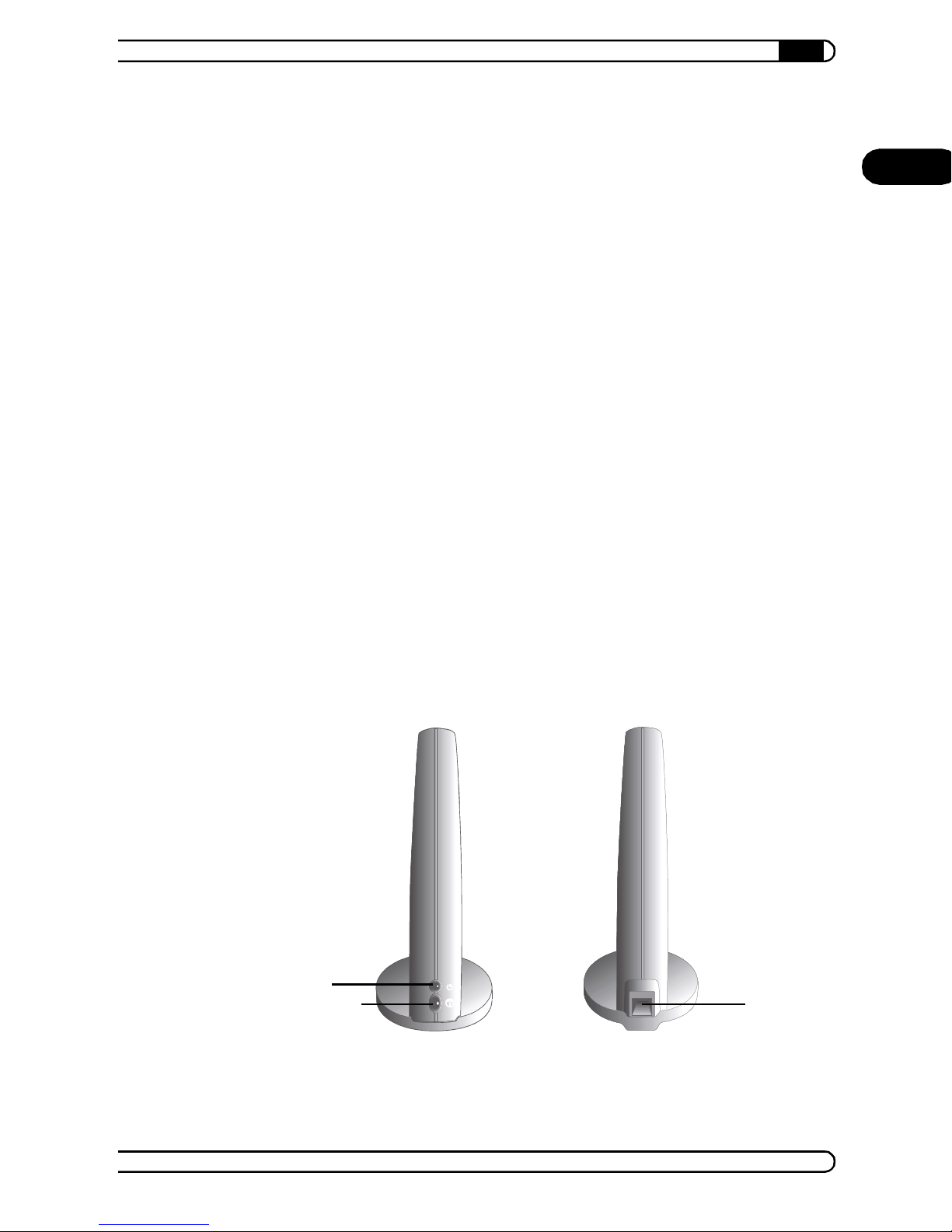
The wireless LAN adapter AirLancer USB-11 is connected externally to
the USB interface of a PC. Power is supplied via the USB interface.
Front side Back side
LED for th e operat ion mode of th e ad ap te r
AirLancer
|
|
Page 24

AirLancer USB-11
24
Off – Device is switched off
Orange – Device is switched on
EN
LED for th e tr an sm iss io n an d receptio n sta t us :
Off – no wireless activity
Blinking – wireless data being sent or received
Green – The device is ready
USB connection
3.3 Installation
The installation of the AirLancer USB-11 takes place in four steps:
햲 Checking the system requirements
햳 Connecting the AirLancer USB-11 to your PC
|
햴 Installation of the drivers
햵 Sett ings fo r the acc ess to th e wirele ss LAN—you wi ll fi nd the in stru ction
for this configuration in chapter 5 'The AirLancer Client Manager' on
page 37.
3.3.1 Checking the system requirements
Before starting the installation process, you should check if your PC fulfills all
system requirements:
At least one free USB port
CD-ROM drive
One of the following operating s ystems:
Windows 98
Windows Millennium Edition (Me)
Windows 2000
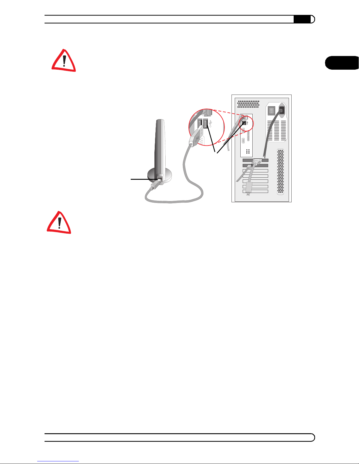
3.3.2 Connecting the adapter to your PC
USB su pports so- called ho t plug ging, i.e. co nnec ting d evi ces wh ile the y are
running. Insert the supplied USB cable into the connection of the
AirLancer USB-11 and to the USB port of your PC while it is running .
AirLancer
|
|
Page 25
|
Onl y use the USB connector cable supplied fo r connecting th e device to your
PC.
The AirLancer USB-11 will be identified automatically (plug&play) and
the installation of the operating software will be started.
AirLancer USB-11
25
EN
If you connect your AirLancer USB-11 with the PC turned off, continue
by boot ing the comp uter and sta rting the in stallation und er your oper ating
system.
Shortly after connecting the adapter, Windows displays a message reporting
the detection of the new hardware.
You will find the appropriate instructions for the installation of any supported
Windows version in the following sections.
3.3.3 Installation of the drivers under Windows 98
햲 Please confirm the 'Add New Hardware Wizard' dialog window with
Next, then select the option Search for the best driver for your
device from the list and click Next.
햳 Enable th e option Specify a location in th e follo wing d ialog windo w
and di sable all oth er op tions . Inser t the AirLancer CD into the CD drive
(e. g. 'D:\').
햴 Use Browse to switch to the folder 'D:\driver\Win98\.. (in whic h
'D:' is the drive letter of your CD-ROM drive).
햵 Confirm with Next to start copying.
AirLancer
|
Page 26

AirLancer USB-11
26
|
햶 Click Finish to ex it ins talla ti on.
EN
On the screen, the window 'Add/Edit Configuration Profil e' opens. This is
where you will configure access to your wireless LAN later. Now please
move on to chapter 5 'Th e AirLancer Client Manager' on page37, in order to
change these settings .
3.3.4 Installation of the drivers under Windows Me
햲 Afte r s tar ti ng th e ' Add New Hard war e Wiza rd ' sele ct th e o ptio n Specify
the location of the driver and click Next.
햳 In the following dialog window, select Search for the best driver for
your device (Recommended).
햴 Disable the option Removable Media (Floppy, CD-ROM...).
햵 Please select the Specify a location option .
햶 Insert the AirLancer CD in your CD drive (e. g. 'D:\'), use the Browse
option to switch to the folder 'D:\driver\Winme\..' (in which 'D:' i s
the drive letter of your CD-ROM drive) an d clic k Next.
햷 Confirm the display of the search results by clicking Next When the
wizard is ready, click Finish to end the installation.
On the screen, the window 'Add/Edit Configuration Profil e' opens. This is
where you will configure access to your wireless LAN later. Now please
move on to chapter 5 'Th e AirLancer Client Manager' on page37, in order to
change these settings .
3.3.5 Installation of the drivers under Windows 2000
햲 Confirm the 'Found New Hardware Wizard' dialog window with Next.
햳 Select the Search for a s uitabl e dri ver for my dev ice op tion a nd c lic k
Next.
햴 In the 'L ocate Drive r Files' d ialog, se lect Specify a location and click
Next.
햵 Insert the AirLancer CD in your CD dr ive (e. g . 'D:'), u se the Browse...
option to switch to the folder 'D:\driver\Win2k\..' (in which 'D:' is
the drive letter of your CD-ROM drive) and confirm with OK.
햶 Confirm the display of the search results by clicking Next.
AirLancer
|
|
Page 27

|
햷 Window s 2 00 0 then in sta lls the dr ive r. W hen the w izar d is re ad y, press
Finish.
On the screen, the window 'Add/Edit Configuration Profil e' opens. This is
where you will configure access to your wireless LAN later. Now please
move on to chapter 5 'Th e AirLancer Client Manager' on page37, in order to
change these settings .
AirLancer USB-11
27
EN
AirLancer
|
|
Page 28

EN
AirLancer USB-11
28
|
AirLancer
|
|
Page 29
4 AirLancer PCI-11
|
AirLancer PCI-11
29
This chapter describes the wireless network card AirLancer PCI-11 and
its set up step by s tep. The c hapter en ds wit h the succ essful in stallati on of
hardwa re and dr ivers. T he follow ing config uration of access t o a wirele ss
LAN is described in chapter 5.
4.1 Package contents
Please ensure first that the delivery is complete. The package should include
the following components:
PCI adapter AirLancer PCI-11
AirLancer MC-11 wireless network card
AirLancer CD including drivers, AirLancer Client Manager and electronic
documentation
User manual
If anything should be missing, plea se cont act your dealer.
4.2 The adapter
EN
The AirLancer PCI-11 allows the installation of an AirLancer
MC-11 into a PC. An AirLancer MC-11 is included in the package
contents.
AirLancer
|
|
Page 30

AirLancer PCI-11
30
|
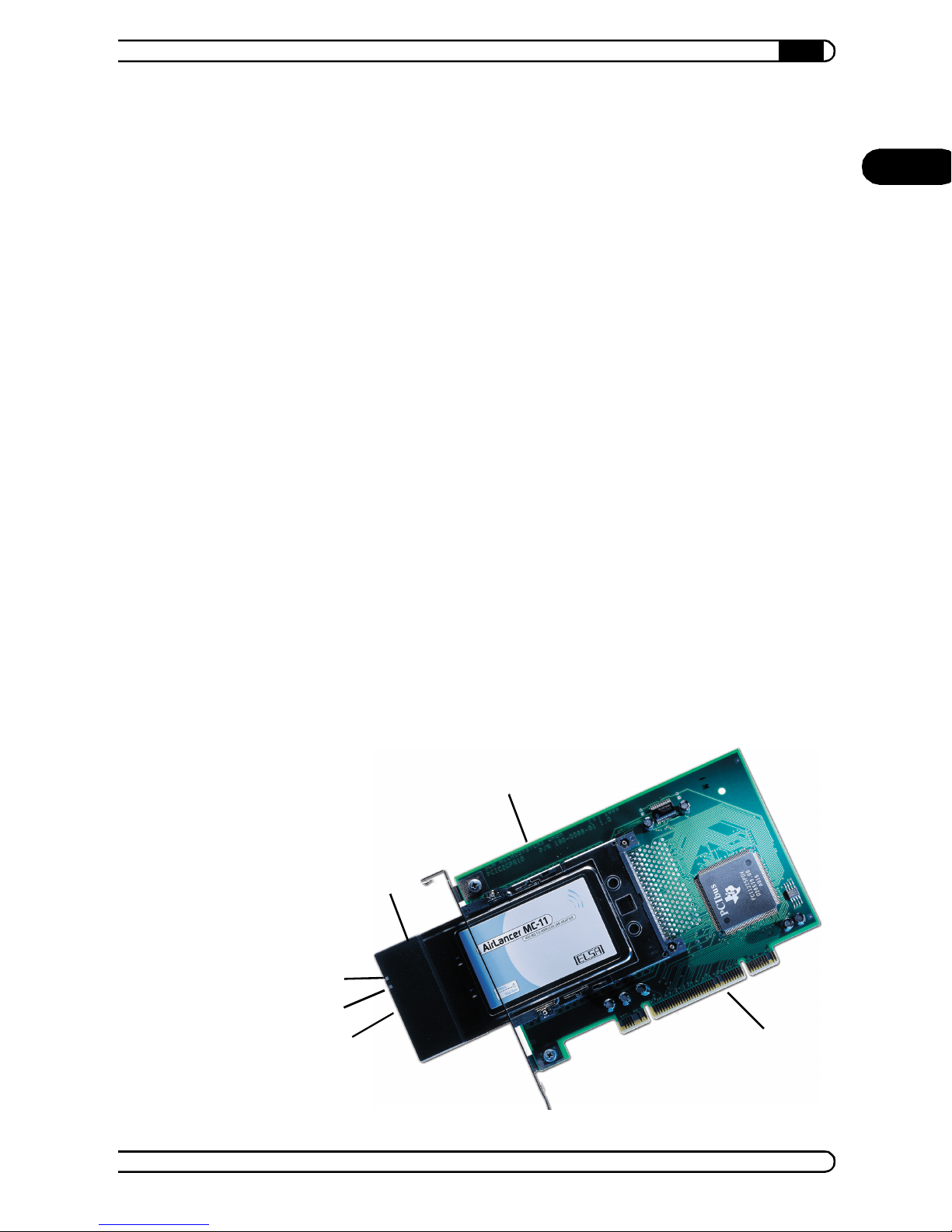
AirLancer PCI-11 – PCI adapter for AirLancer MC-11
EN
AirLancer MC-11 – Wireless LAN card (already inserted into
AirLancer PCI-11)
LED for th e tr an sm iss io n an d receptio n sta t us :
Off – no wireless activity
Blinking – wireless data being sent or received
LED for the operation mode of the card:
Lit green – standard mode
Bli nking green – the card is in energy-saving mode
Contact strip for PCI bus
4.3 Installation
The installation of the AirLancer PCI-11 consists of five steps:
햲 Checking the system requirements
햳 Inserting the AirLancer PCI-11 into your PC
햴 Inserting the AirLancer MC-11 into the adapter
햵 Installation of the drivers
햶 Settings for access to the wireless LAN—y ou will find the instructions
for this configuration in chapter 5 'The AirLancer Client Manager' on
page 37.
4.3.1 Checking the system requirements
Before starting the installation process, you should check if your computer
fulfills all syste m require m ents:
Your PC must have at least one vacant PCI slot (PCI specification 2.1 or
later)
CD-ROM drive
One of the following operating s ystems:
Windows 98
Windows Millennium Edition (Me)
Windows 2000
AirLancer
|
|
Page 31
Windows NT 4.0
Linux
4.3.2 Installing the AirLancer PCI-11
햲 Briefly touch the computer housing to discharge any static electric charge
built up in your body . Ne xt, di sconne ct th e AC power su pply ca ble fr om
the rear of the PC housing.
햳 Remove all retai ning scre ws or relea se the catc hes for th e PC housin g
and remove the cover.
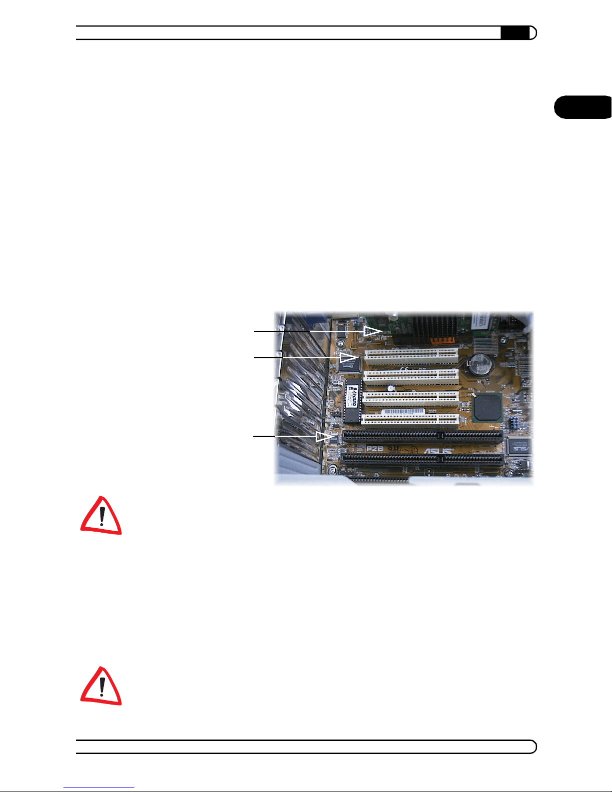
햴 A free PCI slot is required for the installation of the AirLancer
PCI-11. Before installing the card, remove the blind bracket for the slot
you intend to use.
|
AirLancer PCI-11
31
EN
AGP slot
PCI slot
ISA slot
If your computer is equipped with an AGP graphics board, avoid installing
the PCI card in the PCI slot immediately next to the graphics board if
possible. This may lead to an interrupt conflict between the PCI card and
the AGP graphics board.
햵 Carefully insert the AirLancer PCI-11 into the free slot. Ensure that
the card is correctly seated in its slot and tighten the screw of the
mounting plate.
햶 Replace the computer case and screw it tight.
Important step for installation under Windows NT 4.0
The AirLancer MC-11 will be installed with IRQ 10 and the address
range '400–437' by default. For the installation under Windows NT 4.0 please
AirLancer
|
|
Page 32

AirLancer PCI-11
32
ensure that the relevant system requirements are available, before inserting
the card into your computer. The procedure is as follows:
EN
Switch th e c om p ut er on . T he in te rr upts an d addresses ca n be vie w ed unde r
Start Programs Admini strati ve Tool s (Common) Windows NT
Diagnostics.
If the re quired res ou rces are not availab le, pleas e ma ke a no te of ot he r f re e
resources and specify them during the installation. It is also possible to
change the resource allocations at a later time with Start Settings
Control Panel Network Network Adapters Properties.
|
4.3.3 Inserting the AirLancer MC-11
햷 Please insert the AirLancer MC-11 into the PC card slot of the
AirLa ncer PCI -11. Ensure that the PC card is in the correct position. Please
refer to the picture on page29 for a guide.
햸 Switch the computer on.
Afte r swit c hing th e PC on , Win dows re ports th e de tec ti on of t he har dware in
a message th at app ea r s on t he scre en . W ind ow s w ill t he n in stall t he dr iver .
You will fi nd the ap pr opri at e i ns tr uct io ns fo r th e ins ta l l atio n of an y Win do ws
supported version in the foll owing paragraphs.
4.3.4 Installation of the drivers under Windows 98
햲 Please confirm the dialog window 'Add New Hardware Wizard' with
Next, then select the option Search for the best driver for your
device from the list and click Next.
햳 Enable th e option Specify a location in th e follo wing d ialog windo w
and dis able al l othe r optio ns . Insert the AirLancer CD into the CD-ROM
drive (e. g. 'D:\').
햴 Use Browse... to switch to the folder 'D:\driver\Win98\..' (in
which 'D:' is the drive letter of your CD-ROM drive)
햵 Confirm with Next, to start copy in g.
햶 Click Finish to ex it ins talla ti on.
On the screen, the window 'Add/Edit Configuration Profil e' opens. This is
where you will later configure the access to your wireless LAN. Now please
AirLancer
|
|
Page 33

|
move on to chapter 5 'Th e AirLancer Client Manager' on page37, in order to
change these settings .
AirLancer PCI-11
4.3.5 Installation of the drivers under Windows Me
햲 Afte r s tar ti ng th e ' Add New Hard war e Wiza rd ' sele ct th e o ptio n Specify
the location of the driver and click Next.
햳 In the following dialog window, select Search for the best driver for
your device (Recommended).
햴 Disable the option Removable Media (Floppy, CD-ROM...).
햵 Please select the Specify a location option .
햶 Insert the AirLancer CD in your CD drive (e. g. 'D:\'), use the Browse
option to switch to the folder 'D:\driver\Winme\..' (in which 'D:' i s
the drive letter of your CD-ROM drive) an d clic k Next.
33
EN
햷 Confirm the display of the search results by clicking Next. When the
wizard is ready, click Finish to end the instal lation.
On the screen, the window 'Add/Edit Configuration Profil e' opens. This is
where you will later configure the access to your wireless LAN. Now please
move on to chapter 5 'Th e AirLancer Client Manager' on page37, in order to
change these settings .
4.3.6 Installation of the drivers under Windows 2000
햲 Confirm the 'Found New Hardware Wizard' dialog window with Next.
햳 Select the Search for a s uitabl e dri ver for my dev ice option a nd c lic k
Next.
햴 In the 'L ocate Drive r Files' d ialog, se lect Specify a location and click
Next.
햵 Insert the AirLancer CD in your CD dr ive (e. g . 'D:'), u se the Browse...
option to switch to the folder 'D:\driver\Win2k\..' (in which 'D:' is
the drive letter of your CD-ROM drive) and confirm with OK.
햶 Confirm the display of the search results by clicking Next.
햷 Window s 2 00 0 then in sta lls the dr ive r. W hen the w izar d is re ad y, press
Finish.
AirLancer
|
|
Page 34

AirLancer PCI-11
EN
34
On the screen, the window 'Add/Edit Configuration Profil e' opens. This is
where you will con fi gure the acce ss to your wire less LAN later . No w plea se
move on to chapter 5 'Th e AirLancer Client Manager' on page37, in order to
change these settings .
|
4.3.7 Installation of the drivers under Windows NT 4.0
햲 Start the computer and log in with administrator rights.
햳 Insert the AirLancer CD into the CD drive and click Install
AirLancer PCI in Setup.
햴 Follow the on-screen instructions and restart y our computer. Please note
that the PCI Enabler must also be installed!
Perform the following steps to start the PCMCIA card services:
햵 Please open Start S ettings Control Panel, and double-click
Devices.
햶 Sele ct th e PCMCIA en try in th e l ist . Clic k on t he Startup button on the
right-hand side of the window and select 'Boo t'.
햷 Click OK and restart Window s NT.
햸 Start the installation with Start Settings Control Panel
Network. S elect the 'Network Adapter' register tab and click the
Add button.
햹 Press t he Ha ve Disk ... but ton in th e 'Sele ct Net work Adapte r' wind ow,
and enter the following path for the driver data on the AirLancer CD:
'D:\driver\Winnt\..' (in which 'D:' is the drive letter of your CD-ROM
drive). Accept the following prompts to log AirLancer MC-11 as a
network card.
햺 Fi nish the installation and restart your computer.
In the next step you will configure access to your wireless LAN. Now please
move on to chapter 5 'The AirL ancer Cl ient Manager' on page37, where you
will find the descript ion of the required setting s.
AirLancer
|
|
Page 35

|
4.3.8 Installation of the drivers under Linux
AirLancer PCI-11
35
It is not necessary to recompile the kernel in the current Linux distributions.
The PC MC IA comp onent s a re i nc lu de d as m od ules. This short de scr ip tion is
based on SuSE version 7.0.
The adap tat ion s requ ired to th e par amet ers in the f ile
will b e made au to mat i cal ly du ri ng i nst al l atio n of th e PCM CIA p ack et wi th t he
aid of YaST.
To continue setting up the card the file
AirLancer.conf
/etc/pcmcia.
Then the card will log on to the fi rst acc ess point that it f inds.
In order to configure a fixed network name, the following line must be
commented out in the file
module "wavelan2_cs" opts "network_name=MyNetwork"
MyNetwork
See the file README.TXT on the AirLancer CD for additional settings options.
must be replaced by the netw ork name s.
on the AirLancer CD must be copied to the direct ory
/etc/pcmcia/AirLancer.conf:
/etc/rc.config
/driver/mc/linux/
EN
AirLancer
|
|
Page 36

EN
AirLancer PCI-11
36
|
AirLancer
|
|
Page 37
The AirLancer Cli ent Manage r
|
5 Th e AirLancer Client Manager
37
When you insert the AirLancer C D into the C D-ROM drive in Windows 95,
Windows 98 and Windows 2000, setup starts automati cally. In
Windows NT—or if the Autostart function is disabled—start setup
with AUT O RU N.EXE in th e CD ro ot director y .
When installing the AirLancer driver and software, please observe the
licensing regulations.
5.1 Installation
햲 In setup select AirLancer Client Manager.
setup creates a new folder in the status menu for the AirLancer
Client Manag er. You will find the setup program for the AirLancer Client
Mana ger in th e
you select ed a different folder for the installation).
Depending o n the operating system , it may be necessar y to update the
system. In this case the computer must be restarted during the
installation. This will not interrupt the installation process.
EN
\Program Files\ClientManager folder (unless
5.2 Basic configuration
햳 After a su ccessf ul install ation a w indow op ens for the confi guration o f
the standard profile (default) or creating a new profile for the
AirLancer MC-11.
햴 First you can set in th e select ed profi le whe ther you wish t o ac cess an
access point or set up an ad hoc connection (peer-to-peer group).
햵 For advanced settings, please click the Edit Profile bu tto n. I n th e cas e of
an ad hoc network, the following window will ask you for the name of the
network. In the case of an infrastructure network, a further window
opens with four tabs:
AirLancer
|
|
Page 38
EN
The AirLancer Cli ent Manag er
38
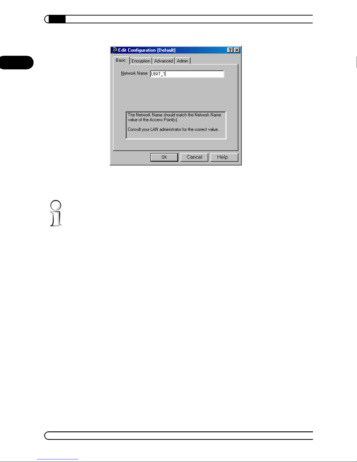
햶 Input the netw ork name. If you are not sure of it, you ca n get it from your
|
network administrator.
The n etwork name ha s to mat ch wit h the ot her dev ices in t he netw ork
(access points or radi o cards). In case you hav e an ac cess po int with a
disabled 'Closed Network' function within radio range, you can also enter
ANY as a net wor k na me . Th e wire le s s s ta ti on w il l t he n lo g on t o th e n ext
availa ble w irele ss LAN. Furth er infor mat ion can be fou nd in t he 'Cl osed
network' on page 49 and in the documentation of your access point.
5.3 Overview of functions
5.3.1 Administration of profiles
Setu p of profiles
Changing to another profile
5.3.2 Configuration
Created profiles can be configured with the Edit Profile butt on .
For ad ho c net works, the ne twork and th e key names are listed in on e
menu.
AirLancer
|
|
Page 39

The AirLancer Cli ent Manage r
|
For access points, the following settings are available:
Assignment of WEP encryption key (Encryption)
Settings regarding power management and radio transmission
(Advanced and Admin)
5.3.3 Analysis, diagnostics and information
In the Advanced menu of t he AirLan cer Client Manager yo u will f ind the
diagnostics functions for the wireless LAN and your own wireless LAN
interface:
Card test and diagnostics (Card Diagnostics)
Signal strength monitoring (Link Test)
Monitoring and analysis of the wireless network (Site Monitor)
Display of the available access points (Site Monitor Selection)
39
EN
5.3.4 Further information
For more detailed information see the AirLancer Client Manager online help .
5.4 Encryption settings
Under Encryption, you enter the key to secure the co nnectio n in the entire
wireless LAN.
5.4.1 General rules for WEP keys
Please note the following instructions:
Matching keys mus t be used between devices.
In ad hoc networks, all devices use a common key. In infrastructure
networks, all keys between the access point and the radio stations must
match.
WEP64 (40-bit ke y length) and WEP 128 (104- bit key len gth) cann ot be
used paralle l at an access poin t. To give users encrypted acce ss to an
access po int w ith W EP64 de vic es, th e encr yptio n s etti ngs a t the acce ss
point must be set to WEP64.
Wireless LAN interfaces with WEP128 are backwards compatible to
WEP64. A WEP128 device automatically logs onto the WEP64 encrypted
access point using the short key.
AirLancer
|
|
Page 40
The AirLancer Cli ent Manag er
40
|
5.4.2 Valid key characters
EN
Keys c on sis t of either al ph anumer ica l st rings of n um be rs '0'–' 9', low e r-ca se
letters 'a' –'z' an d upp er- case letter s 'A '–'Z' or of he xad ecim al valu es '0'–'9'
and 'a'–'f'.
Special characters are not valid.
On entering hexadecimal values, the number of characters for a key is
doubled. For WEP64, 10 hexadecimal numbers must be entered, for WEP128
26 are entered.
Many W EP- co m pa tib le wir el ess LAN devices from ot he r m an uf act ur er s on ly
accept a hexadecimal format for the key or even generate their own special
key values on the basis of user-defined passwords.
You may have trouble entering a key that accepts your AirLancer
with out a prob lem, when us ing a d evice from anot her manu fa ctur er. In this
case, we re co mme nd that yo u u se the k ey o f th e l ess fle xib le device f or th e
connection.
5.4.3 Continuous change of key
Using an infrast ru ctur e networ k, yo u ca n enter u p to four keys in the key li st
of the access point. This simplifies the changing of keys. In this case, all
entere d k e ys ar e v a lid in th e w ir ele ss LAN durin g t he tr ans it ion al p er iod . A s
soon as all stations have been set, the old key can be deleted from the list.
The continuous change of keys of an access point should not be mistaken for
the optional four entries in the key list of an AirLancer. For each
AirLan cer on ly o ne key is use d, i.e. the cur r en tly selected en tr y fr om t he key
list.
AirLancer
|
|
Page 41
Example configur ations
|
6 Example configurations
41
In this chapter we present two examples of the use of AirLancer.
6.1 Direct PC connectio n
Even small companies, branches and offices with small numbers of
employ e es a re increasi ng ly us ing th eir comp ut e r w or ks t at io ns n ot sim ply as
isolated solutions but they are a lso linking the individual computers, printers
etc. to form a common structure, a network.
The Windows operating systems, used in most cases, include everything
required for connecting several computers to a network. The wireless
network cards even make it unnecessary to wire the computers
together. A small Windows network in which every computer can have
“wireless” access to the released files, folders and printers on the other
computers can be set up very quickly.
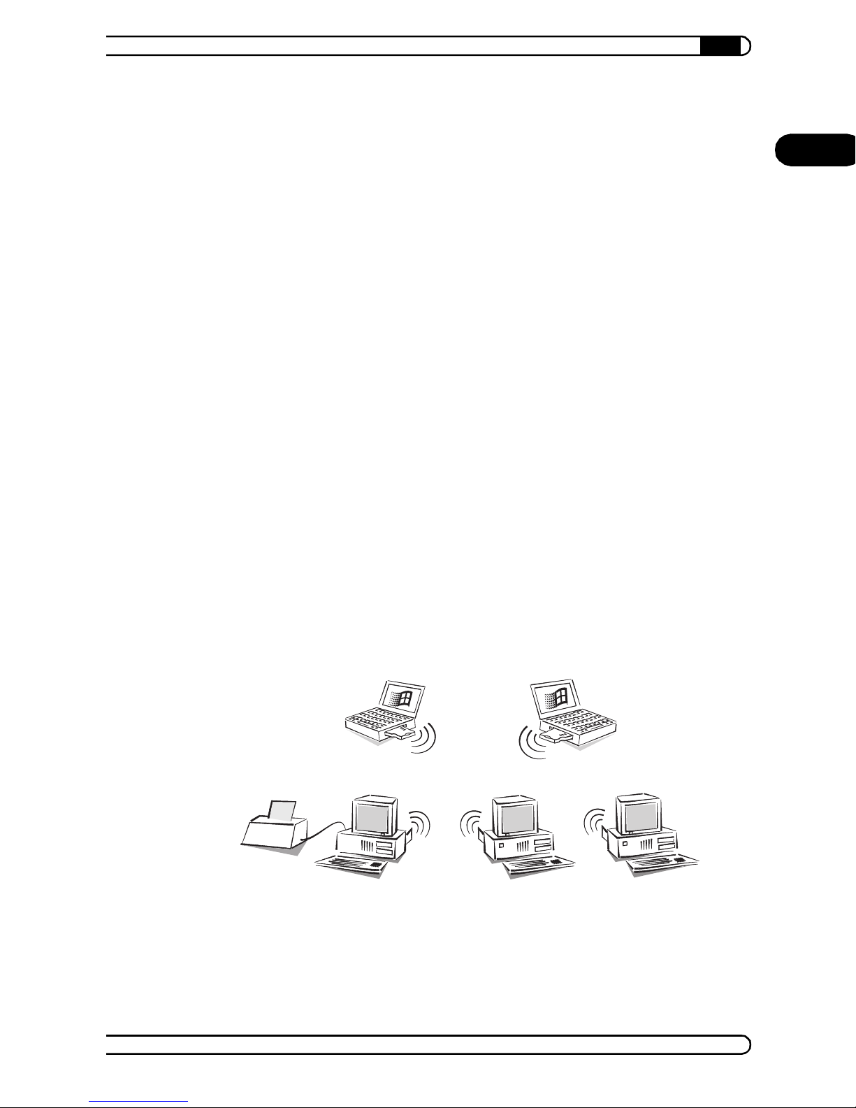
We sh all take a small arch itectur al offi ce as an exam ple of a peer-to -peer
networ k (or a d hoc net work). Tw o archi tects and one as sistan t work in the
office. Each of the three has a desktop PC, and a printer, used by all three, is
connected to the assistant's computer. The two architects also have
note bo ok c o mp ut er s to keep t hem u p to date du ri ng external a ppoint me nt s.
It should be possible to exchange data between the notebooks and the
desktop PCs a nd the note books shoul d also be able to access the printer
quickly at any time.
EN
In this case all computers are fitted with AirLancer MC-11 wireless
network cards, and the desktop PCs are also fitted with the AirLancer
PCI-11 PCMC IA adapters.
Ad hoc network
AirLancer
|
|
Page 42

Example configur ations
42
|
Se tt ing up t h e
wir eless network
cards
EN
Operating system
settings
To enable the wireless network cards to detect one another and exchange
data with one another, the various parameters must have the same values.
Open the configuration for AirLancer MC-11 with Start Programs
AirLancer PC Card Settings.
Diff er en t p rof i le s ca n b e set up i n t he di al og wi nd ow. F or the 'De fa ul t' pr of il e
change the entry 'Access Point' to 'Peer-to-Peer Group'. Then click Edit
Profile to set the network name.
Setting the network name
This setting is always required. Enter the name of the network in the 'Basic'
tab. This name must be the same for all PCs in the wireless network.
The question mark has the answer! If you have
questions about a specific setting, first try clicking on
this symbol and then on the area that you wish to
know more about.
After installing and setting up the drivers for AirLancer PCI-11 and
AirLancer MC-11 in all computers, some components in the operating
system—us i ng Wind ow s 98 as an exam pl e—still need to be set up.
Network protocol
The network protocols TCP/IP and NetBEUI are required to implement a
peer-to-peer network with the wireless network cards. Install the
prot ocols if they are not already installed and check the protocol links to
the AirLancer MC-11 wireless network card in the control panel.
Client
The Windows network client is required to permit all of the workstations
in the Windows network to log on with names and passwords.
Service
File and printer sharing permits drives and printers to be shared with
other users in the Windows network.
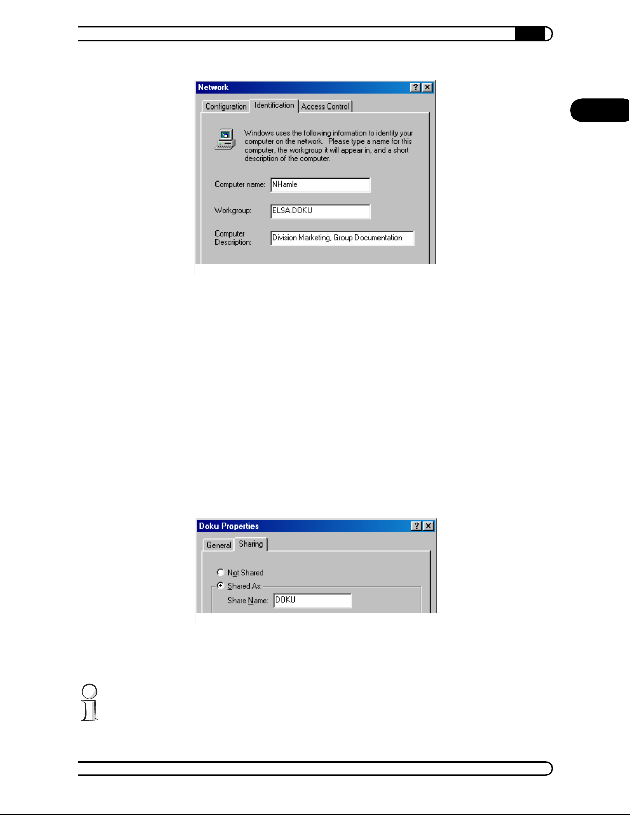
Name and group designation
Click Start Setti ngs Cont rol Panel Network and switc h to the
'Identification' ta b.
AirLancer
|
|
Page 43
Example configur ations
|
The name of the workstation must be unique. Names also may not recur
in different groups.
The workgroup must be set the same for all comp uters that are intended
to exchange data and resources.
43
EN
File and printer sharing
Ensure that file and printer sharing is enabled after the installation is
complete. Click Start Settings Control Pane l Network File
and Print Sharing. Specify whether other users in the Windows
network should be allowed access to the printer and/or files of this
workstation.
In the Wi ndows E xplorer, ri ght-click the drives, folders or printers t hat
you w ould l ike to sha re w ith ot her s on the n etw ork an d sele ct the it em
'Sharing' from the context menu.
Ente r a n ame for t he sh ared re sour ce an d a descr iptio n if re quire d. Th e
manner in whic h the res ource can be access ed can b e selected under
access typ e, and by en te rin g pa s sw or ds as requ ir ed .
It's easy to check whether the Windows network settings have been made
correctly: the local computer must appear with its name in the Network
Neighborhood.
AirLancer
|
|
Page 44

Example configur ations
44
|
Access to other
resources
EN
Short ly after a c ompu ter has be en start ed in a Wind ows ne twork, the user
can see the names of all other currently accessible computers in the network
in the Wi ndows Explo rer Netwo rk Neighbor hood (includ ing the use r's own
computer).
The re le as e d fo lde rs an d fi les ar e a s e asi ly acc e ssi bl e in Ex pl or er as th e ha rd
disks and drives in the user's computer.
6.2 Link to a company network
As well as settin g u p i nd ependen t ne tw or ks , th e se c on d g r eat a dva nt ag e o f
the wireless network is the ability to expand existing wired networks. It
make s no differ ence here w hether t he existing LAN is to b e extend ed but
wiring the new workstations is uneconomical or impossible or whether, for
example, external employees should have a mobile link to the LAN during an
internal assignment.
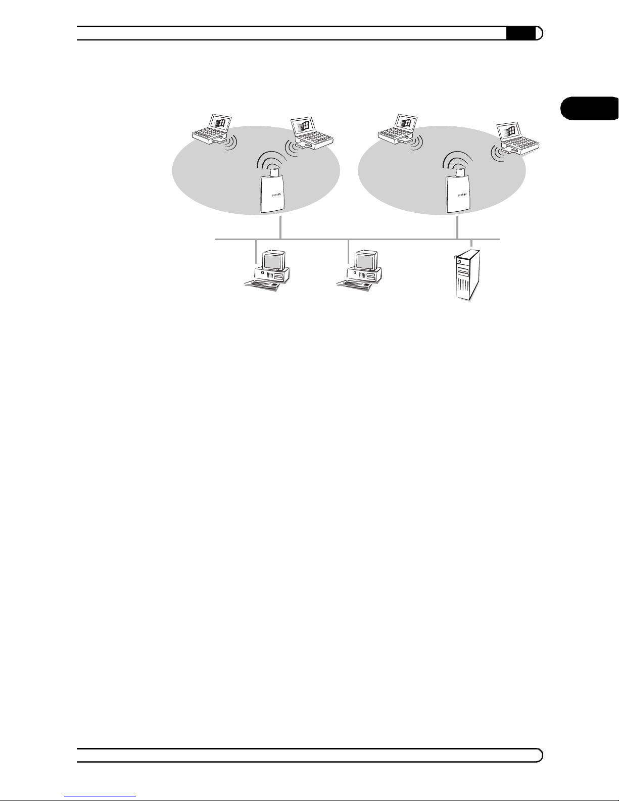
For example: I n the
sales department
We shall use the sales department of a medium-sized company as an
exam ple for an inf rast ruct ure net wor k. The s ales em ploye es are tr ans ferre d
to another floor. Because they are usually out in the field in any case, the new
workstations are not fully wired but an access point, such as the
LANCOM Wireless L-11, is used to access the company LAN. Additional
access points are installed because the sales employees need network
acc ess fo r t heir no te bo oks i n ot her d ep ar tme nt s of th e c o mpa ny. Th ey e na bl e
a sales employee to access the network anywhere inside the company
premises. When the employee moves into another wireless cell, the stations
automatically log off from the former access point and log on to the new
access poi nt. The procedure is known as roaming.
AirLancer
|
|
Page 45
Example configur ations
|
45
Level A
Company netw ork (wired)
Level B
Every sales employee receives an AirLancer MC-11 wireless network
card for the not eboo k comput er so the employ ee can lo g into th e com pany
network while in the office. To enable the sales employees to print, a network
printer connected to the wired LAN is installed in their office.
EN
Encryptio n based
on WEP
To enable the wireless network cards in the notebooks to log on to the access
poin t an d ex c hang e da ta wi th t he LA N, t he v ari ou s pa ra me te rs mu s t ha ve t he
same v alue s as the wi re le ss ne two rk card in th e acc ess poi n t. You on ly ne ed
to specify the domain setting to be able to set up the first net w ork contact.
Setting the network name
This setting is always required. Input the name of the network in the 'Basic
Settings' tab. This name must be the same for all PCs in the wireless network.
You can set your own profile for multiple wireless LANs in the AirLancer
Client Ma na ger.
If you use your notebook both in the office and at home, it is wise to create
two profiles: one 'Wor k' profile for the office and a 'Home' profile for private
use. In case you wish to work at home at night or during the weekend, just
switc h to the ' Home ' p rofile, an d swi tch b ack to t he 'W ork' p rof ile th e ne xt
morning.
Encryption of wireless data
On the 'Encryption' index card you can specify up to four different
alphanumerical (5 or 13 characters) or hexadecimal (10 or 26 characters)
AirLancer
|
|
Page 46

EN
Example configur ations
46
|
codes, thereby ensuring that the transmission of the wireless data cannot be
easily intercepted. This is also backed up by the standardized WEP process,
which encrypts the wireless data.
Checking the network protocols
Check the properties for AirLancer MC-11 in Start Settings
Control Panel Network. The TCP/IP protocol should always be marked
in the list window of the 'Bindings' tab. Novell networks will require
additional IPX/SPX protocols.
For information on configuring the access points, please refer to the
documentation on LANCOM Wireless L-11 and LANCOM
Wireless I L-11 and to the el ectronic documentation on the CD.
Access to the LAN
After setting up the wireless network cards, all functions and services
available on the desktop PCs in the wired network will be available for the
sales em plo y e es wi th their no te book com pu t er s. The s e inc lud e:
File server (Novell, NT or other)
Network printer in the sales department
Internal mail system
Internet through the LAN
AirLancer
|
|
Page 47

7 AirLancer Extender
|
AirLancer Extender
47
The AirLancer Extender is the optimal addition to a wireless LAN if you
wish to extend your range. The omnidirec t ional antenna offers about 2.5 dBi
more transmission and reception capacity (taking into consideration line
losses). The AirLancer Extender can be flexibly positioned for optimized
ran ge and transmission characteristic s.
It can be connected to both AirLancer wireless adapters (MC-11, USB-11,
PCI-11) and LANCOM Wireless access points (L-11 and IL-11).
EN
The installation is quite simple: Every wireless LAN device has a socket
where the AirLancer Extender is plugged in except AirLancer USB-11.
AirLancer
|
|
Page 48

EN
AirLancer Extender
48
|
AirLancer
|
|
Page 49

Security in the wireless LAN
|
8 Securit y in the wire less LAN
49
Signifi cant secu rity consid erations app ly to the us e of wireles s LANs . It is
often assumed that unauthorized access to transmitted data is relatively
easy.
However, wireless LAN devices permit the use of modern security
technology:
Close d ne tw or k
Access control via MAC address
Encryption of the data transfer (WEP)
8.1 Closed network
Ever y IEEE 802.11 wireless LAN has a network name (IBSS-ID). Thi s network
name is used for the identi fication and administration of wireless LANs.
A wireless LAN can be set up in such a way as to give access to the network
to any us e r. T hese n et wor k s ar e cal le d op en n et wor k s. A user c an l o g onto an
open n etw ork wit hou t th e ne two rk n ame. A cces s i s ga ined by ent erin g th e
network name 'ANY'.
EN
Acces s th ro ugh 'AN Y' is im po ssi b le in a c lo sed ne tw or k . Here the us er mu s t
enter the correct network name. Unknown networks remain out of reach.
Ad hoc networks are automatically set up a s closed networks and c annot be
opened. Infrastructure networks can be operated in an open or a closed
mode. The settings can be changed at the access point.
8.2 Access control via MAC addre ss
Every network device has an unambiguous serial number. This serial number
is called a MAC address (Media Access Control) and is unique to the world.
The MAC address is hardwired and cannot be altered. You will find the MAC
address on the case of your wireless LAN device.
Access to an infrastructure network can be set for specific wireless LAN
devices by specifying the MAC addresses. Filter lists are included in the
access stations containing the MAC addresses controlling access.
This access control method is not available in the ad hoc network.
AirLancer
|
|
Page 50

Secur ity in th e wir e less LA N
50
|
8.3 Encryption of the data transf er (WEP)
EN
The enc ryption of the transfe rred data pla ys a special p art in the wir eless
LANs. The supplementary encryption standard WEP is available for IEEE
802.11 radio transfer. WEP means Wired Equivalent Privacy. The aim of WEP
is t o gu ar an te e th e de gr ee o f s e c urit y of c a ble- ba s ed L ANs in wi r el es s L A Ns.
8.3.1 How WEP works
WEP encrypts frames on level 2 of the OSI model. WEP automatically protects
any data of higher protocols (especially IP packet s).
WEP uses the established RC4 encryption algorithm of the American
crypt ogra phy sp eci alist RSA D ata S ec urity , Inc. Two ver sions with di fferen t
key lengths are used:
WEP64
The nominal key length is 64 bits, of which 40 bits (5 characters of 8 bits
each) are user-defined.
WEP128
The nom inal key l en gth is 1 28 bit s, of wh ich 104 bi ts (1 3 c h ar act er s of 8
bits each) are user-defined.
The shorter effective key lengths are related to the encryption method of the
RC4 algorithm. RC4 uses the remaining 24 bits to generate a unique key for
every block that needs to be encrypted. These 24 bits form the so-called
“initialization vector”.
Encryption requires computing resources on the part of the wireless LAN
device and has an impact on the transmission rate. With AirLancer the
speed loss may reach up to 15% independent of the key length used.
8.3.2 Notes for the correct use of keys
By following some important rules regarding the use of keys, you can improve
the security of the encryption process considerably.
Keep your keys as secret as possible.
Never write a key down. Popular, but completely unsuitable storage
options include: note-books, wallets, and text files in your computer. Do
not pass on your key unnecessarily.
Choose a random key.
Use randomly chosen letter and number sequences. Keys that consist of
actual words are not secure .
AirLancer
|
|
Page 51

|
Change your keys at a regular basis.
Keys should be changed as often as possible. This requires some effort
but improves security considerably. In the infrastructure network, it is
possible to gradually change keys (see page 40).
If you have any suspicions, immediately change a key.
When an employee who has access to a key leaves the company, change
the keys of the wireless LAN immediately. Even if only the slightest
indication of a leak exists, the key should be changed.
8.3.3 Further security improvements
Using WEP, it becomes difficult or even impossible for outsiders to gain
access to the transmitted data. Like any technology, WEP has its limitations,
although it offers a sufficient level of security in most practical cases.
It may th er ef ore be usef ul to ap ply ad di tio na l se cu ri ty te c hn olo gi es at a mo re
advanced protocol level. Modern IPSec products (on level 3 of the OSI model)
allow separate protection of the users in the wireless LAN. They also simplify
the administration through automatic key management. The applies to
applications such as SSL, PGP and S/MIME.
Security in the wireless LAN
51
EN
Any of these technologies can be applied to a WEP secured wireless
connection, just as they use the ”naturally” protected cable in the
conven t ion al ne tw ork as a basi s of com m un i ca tio n.
AirLancer
|
|
Page 52

EN
Secur ity in th e wir e less LA N
52
|
AirLancer
|
|
Page 53

9 Appendix
9.1 Technical data
Frequency band 2.4GHz: 2400–2483.5 MHz (ISM)
Range 11 Mbps 5.5 Mbps 2 Mbps 1 Mbps
open envir onment 150 m 250 m 300 m 400 m
closed environment 30 m 35 m 40 m 50 m
Delay Spre ad 65 ns 225 ns 400 ns 500 ns
Appendix
|
53
EN
Modulation
technology
Antenna integrat ed 2 dBi dipole antenna
Bit error rate better than 10
Transmission
power
Standard IEEE 802.11b, DSSS (Direct Sequence Spread Spectrum)
Safety WEP64 models: RC4 with 40-bit effective key length
Connects PC card
Operating
systems
Power intake
(PC card)
CCK for high and medium transmission rates (High and Medium)
-5
15 dB m
WEP128 mod els: RC4 with 104- or 40-bit effective key le ngt h
AirLancer MC-11 AirLancer USB-11 AirLancer PCI-11
USB interf ace PCI bus (Spec. 2.1 or
(PCMCIA , ty p e II)
Windows 98,
Windows 95,
Windows Me,
Windows 2000,
Windows NT 4.0,
Windows CE, Linux
doze mode -9 mA, re ceive mode -185 mA, trans it mo de -28 5mA
Windows 98,
Windows Me,
Windows 2000
higher)
Windows 98,
Windows Me,
Windows 200 0,
Windows NT 4.0,
Linux
Package cont ent s elabor at ed doc um entation in Germa n, English, French and
Service warranty : 2 ye ars
Italian
support : via hotline and Internet
AirLancer
|
|
Page 54
Appendix
54
|
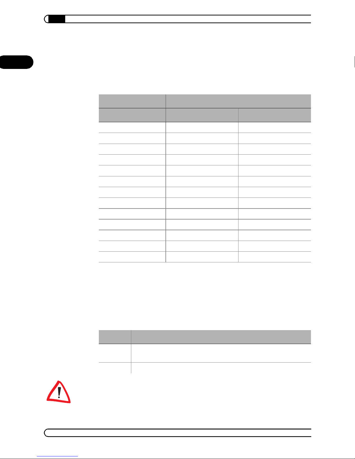
9.2 Radio channels
EN
Up to 13 DSSS channels are available in the usable frequency range of 2400
to 2483 MHz . The follo wi ng ove rview sh ows w hic h cha nnels are s upp orte d
by the diff erent device versions (EU/WORLD).
Frequenc y ra nge 2400–2500 MH z
Channel no. EU (CE) WORLD (CE + FCC)
1 2412 2412
2 2417 2417
3 2422 2422
4 2427 2427
5 2432 2432
6 2437 2437
7 2442 2442
8 2447 2447
9 2452 2452
10 2457 2457
11 2462 2462
12 2467 –
13 2472 –
The values in bold are the default settings with which the AirLancer wireless adapter in the
access point operates.
9.3 Restrictions for use withi n EU countries
At the time of printing, the following restrictions applied to the use of
wireless LAN devices in the following EU countries:
Country Restriction
France O nly t he channels 10 (2457 MHz) and 11 ( 2462 MHz) can be used. A license is
needed for both outdoor and indoor use.
Italy A license is nee ded f or i ndoor use. Outdoor use i s not al lowed.
Pleas e inf o rm you rs elf on th e cur r en t r adi o r eg ula ti ons of the cou nt r y wh er e
you are planning to use a wireless LAN device.
AirLancer
|
|
Page 55

9.4 Declarations of conformity
Appendix
|
55
9.4.1 European Union (CE)
The declarations of conformity for the CE standard of the European Union are
available for download on the LANCOM web site (www.lancom.de).
9.4.2 Federal Communications Commission (FCC)
AirLancer MC-11 and AirLancer USB-11
The radio adapters AirLancer MC-11 and AirLancer USB-11 have
been tes te d and meet the req uirem ent s fo r dig ital cl ass B devic es in acc ordance with section 15C of the guidelines as provided by the Federal Communications Commission (FCC). The FCC ID is: IMR WLPCE24H .
These limits are designed to provide reasonable protection against radio
frequency interference in a residential installation. This equipment
gener ates , use s, and can r adiat e rad io fr eque ncy en ergy . It may in terfe re with
radio communications if not installed and used in accordance with the
instructions.
However, there is no guarantee that interference will not occur in a particular
installation. If this equipment does cause interference to radio or television
reception (this can be determined by turning this equipment off and on), the
user is encouraged to try to correct the interference by one or more of the
following measures:
EN
Reorient or relocate the receiving antenna.
Increase the distance between this equipment and the receiver.
Connect the equipment to an outlet on a circuit other than that to which
the receiver is connected.
Consult your dealer or an experienced radio/TV technician.
The Fede r al Co mmu nicatio ns Com mi s sio n wa rns the user tha t cha nges or
modifications to the unit not expressly approved by the party responsible for
compliance could void the user's authority to operate the equipment.
AirLancer
|
|
Page 56

Page 57

Page 58

Page 59

Page 60

 Loading...