

ELRO M300 Series, T300 Series Installation, Operation And Maintenance Manual
ELRO
®
Peristaltic pumps
Series M300
Series T300
Installation, Operation and Maintenance
BACD-M300-GB/01.04/Be

2
Peristaltic pumps Series M300 / T300

3
Peristaltic pumps Series M300 / T300
Declaration of Conformity
in compliance with the machine directive 98/37/EC
We hereby declare, that the pump units manufactured in series production
Designation: ELRO – Peristaltic Pump
Series: M300, T300
Manufacturer: Crane Process Flow Technologies GmbH
Heerdter Lohweg 63-71
D-40549 Düsseldorf
Germany
Serial number: (see identification plate)
in the version delivered by us, is in compliance with the following applicable
regulations:
EC-machine directive: Machine directive 98/37/EC
Low voltage directive 73/23/EC
EMC-directive 89/336/EC
Harmonised standards: EN 292 T 1 and T 2; EN 294, EN 809
Data / signature of manufacturer: 28.5.2002
Information on signatory: H.-D. Ptak, Managing Director

4
Peristaltic pumps Series M300 / T300
Declaration of Manufacturer
in compliance with the machine directive 98/37/EC
We hereby declare, that the pump units manufactured in series production
Designation: ELRO – Peristaltic Pump
Series: M300 (without drive)
Manufacturer: Crane Process Flow Technologies GmbH
Heerdter Lohweg 63-71
D-40549 Düsseldorf
Germany
Serial number: (see identification plate)
in the version delivered by us is to be installed in a machine and that any operation is
prohibited, unless it has been confirmed that the machine to be fitted with this pump
is in compliance with the EC machine directive, edition 93/44/EEC.
EC-machine directive: edition machine directive 98/37/EC
Harmonised standards: EN 292 T 1 and T 2; EN 294, EN 809
Data / signature of manufacturer: 28.5.2002
Information on signatory: H.-D. Ptak, Managing Director

5
Peristaltic pumps Series M300 / T300
according to Directive 94/9/EC for equipment intended for use in
potentially explosive atmospheres
The manufacturer Crane Process Flow Technologies GmbH,
Heerdter Lohweg 63-71, D-40549 Düsseldorf,
declares, that the pumps produced in series production
Designation : ELRO Peristaltic Pumps
Series: GUP 3-1,5 and GP20/10 Ex
M300 incl. drive and accessories
Material:
Hose: Nitrile (NBR), Hypalon (CSM), Natural rubber (NR),
all hoses are electrically conductive
Connecting port: Stainless steel, bronze; PP electrically conductive
Base frame: Fire brigade frame stainless steel or steel galvanized
Pulsation dampener: Stainless steel with diaphragm out of CSM, electrically conductive
Suction and
discharge hose: EPDM electrically conductive
Drum and suction
accessories: Stainless steel
Drives: Drives have separate declaration of conformity issued by supplier
and in addition water turbine, hydraulic- and air motor
Assembled All electrical equipments have separate declaration of
electrical units: conformity issued by supplier
are according to the following applicable standards:
EC-directive: Directive 94/9/EC for equipment intended for use in
potentially explosive atmospheres
Conformity assessment Group II; Category 2G
procedure: Protection by constructional safety, type „c“
Temperature class T3
(max. surface temperature <200°C)
Harmonised standards : EN 13463-1 ( for accessories )
EN 13463-5 ( for accessories )
Date / signature of manufacturer: 3.07. 2003
Information on signatory: H.D. Ptak, Managing Director
ATEX 100a
Declaration of Conformity

6
Peristaltic pumps Series M300 / T300
Table of Contents
Page
1.0 General ...................................................................................................................8
1.1 Warranty .................................................................................................................. 8
1.2 Transport, storage ...................................................................................................9
1.3 Function ................................................................................................................... 9
2.0 Safety.................................................................................................................... 11
2.1 General .................................................................................................................. 11
2.2 Intended use .......................................................................................................... 12
2.2.1 Unintended use ..................................................................................................... 12
2.3 Operation of pump ................................................................................................. 12
2.4 Conversions and alterations to the pump .............................................................. 12
2.5 Symbols and notes on safety ................................................................................ 12
2.6 Maintenance work ................................................................................................. 13
2.6.1 Health and safety information on electric equipment ............................................ 14
2.6.2 Health and safety information for work on pressure lines ..................................... 14
2.6.3 Regulations and instructions on lubrication ........................................................... 14
2.7 Noise ..................................................................................................................... 16
3.0 Notes on Application...........................................................................................16
3.1 Points to be observed before use .......................................................................... 16
3.1.1 Pump suction power .............................................................................................. 16
3.2 Installation ............................................................................................................. 16
4.0 Operating Instructions ........................................................................................17
4.1 Points to be observed before commissioning........................................................ 17
4.2 Commissioning ...................................................................................................... 17
4.3 Taking out of service .............................................................................................. 17
5.0 Maintenance......................................................................................................... 18
Standard installation (spare parts for pump, spare parts for gearbox
spare parts kit) .................................................................................................. 19-21
5.1 Cleaning ................................................................................................................ 22
5.2 Replacing the pumping hose ................................................................................. 22
5.3 Replacement of separating part ............................................................................ 24

7
Peristaltic pumps Series M300 / T300
5.4 Replacement of abutment ..................................................................................... 25
5.5 Checking the V-belt tension................................................................................... 25
5.6 Oil change ............................................................................................................. 26
5.6.1 Pump housing ....................................................................................................... 26
5.6.2 Gearbox ................................................................................................................. 26
5.6.3. Oil types ................................................................................................................ 26
5.7 Shaft bearings ....................................................................................................... 26
6.0 Trouble Shooting................................................................................................. 27
7.0 Technical Data ..................................................................................................... 28
8.0 Appendix ..............................................................................................................29
Applicational recommendations ............................................................................ 30
8
Peristaltic pumps Series M300 / T300
1.0 General
The following instructions refer only to the
peristaltic pump M300 and T300.
Since the pumps will be used in combination
with other assemblies, such as combustion
engines and electric motors, you must strictly
observe and comply with the operating and
maintenance instructions for these
components as well as the corresponding
notes on safe and reliable operation.
These on-hand instructions contain
information for installation, operation and
maintenance of ELRO pumps.
You should thoroughly read these
instructions before use and always follow the
information contained therein.
All personnel involved in activities on pump
or equipment must have read this manual,
especially the chapter ”Safety” before
starting work. This applies especially for
persons who work on the pump only
occasionally, e.g. for maintenance and
cleaning work.
Each pump is subjected to stringent
inspections and function tests before
leaving the factory.
You should always bear in mind that the
correct function, long lifetime and optimal
operational reliability of the pump mainly
depend on
correct installation
correct commissioning
and proper maintenance.
Enquiries concerning service, spare parts
or repairs should be addressed to the
manufacturer or an authorized dealer.
Always provide the following information:
Pump type
Serial number of pump
This information is stamped on the
identification plate on the base of the pump.
When returning pumps or pump parts to the
manufacturer or an authorized dealer for
repair or overhaul, the delivery must be
accompanied by a certificate stating that
the pump is free of product or other aggressive or hazardous substances.
1.1 Warranty
Each ELRO peristaltic pump is checked in
the factory before shipment. The
manufacturer assumes warranty for his
product as specified in the effective terms
of sales and delivery. Faults resulting from
the non-compliance with the afore
mentioned regulations and notes can only
be rectified at the cost of the customer.
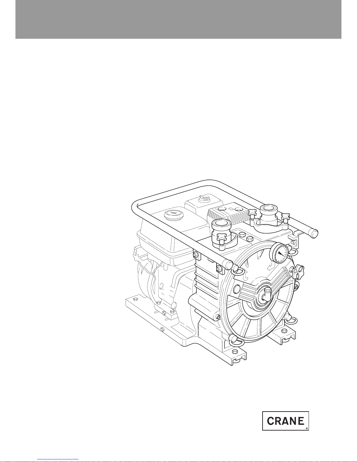
Fig. 1: Exemplary installation for peristaltic

9
Peristaltic pumps Series M300 / T300
1.3 Function
The priming properties of the peristaltic
pump are based on the vacuum backed
restoring force of its hose. Due to its
special design a vacuum is permanently
generated inside the hose on the suction
side of the pump. The vacuum always
restores the hose to its original size. As a
result of this the pump attains max.
pumping capacity.
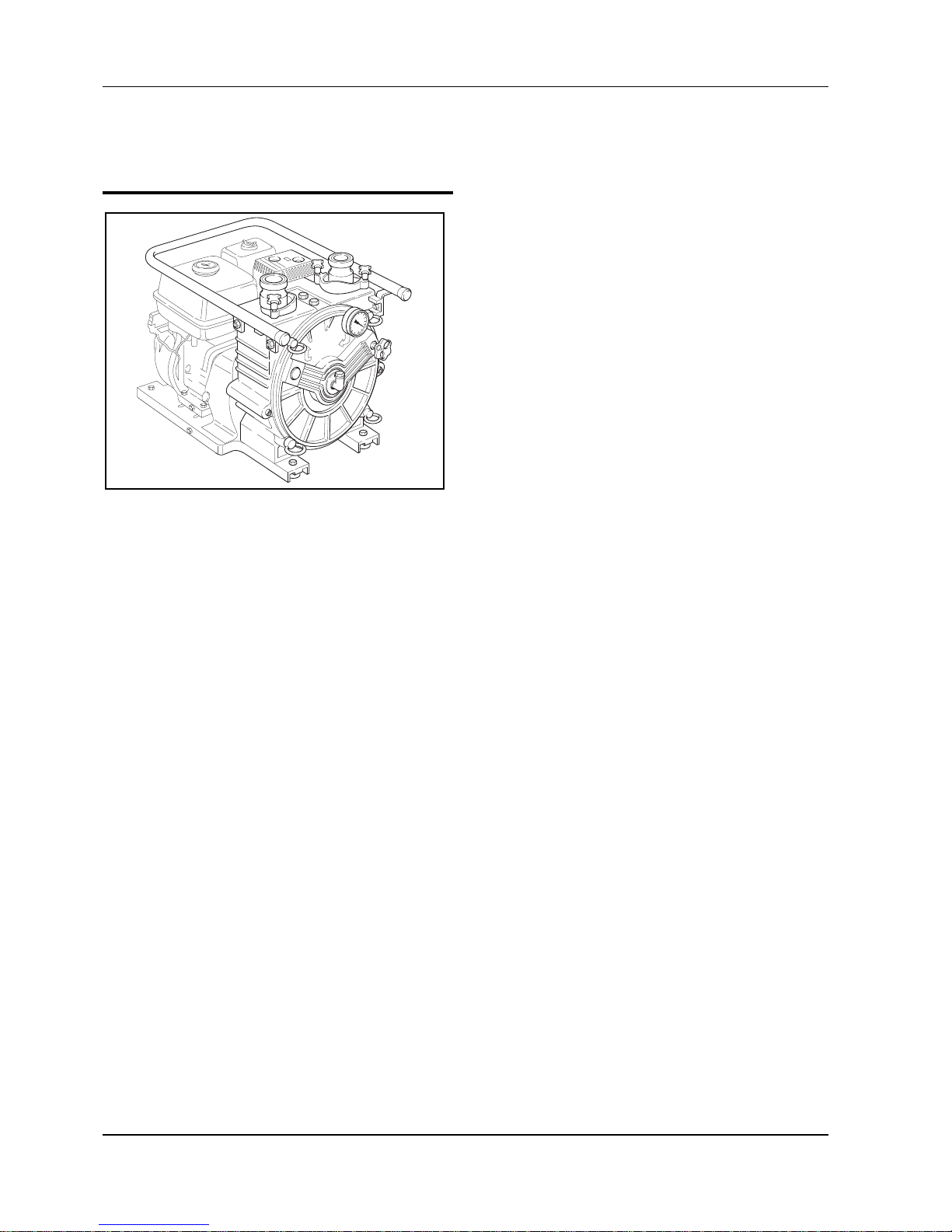
Fig. 2 - Attaching the lifting rope
1.2 Transport, storage
In order to avoid any problems you should
check the delivered goods against the
delivery note for completeness and
correctness,
make sure that for pumps with electric
motor, combustion engine, water
turbine, hydraulic motor or pneumatic
motor the respective operating
instructions for the drive are available.
Be careful when unpacking the pump and
proceed as follows:
Examine the packaging for transport
damage.
Take the pump carefully out of the
packaging.
Examine the pump for any visible
damage.
Remove all plugs from the pump ports.
Make sure that accessories, such as
seals and flushing lines, are free of
damage.
Consider the indicated weight
before attempting to lift the
pump. Use only lifting gear of
appropriate capacity.
Do not step or stand under
suspended loads.
Fasten the lifting gear so that the pump (or
pump with drive unit) can be safely lifted
(see example).
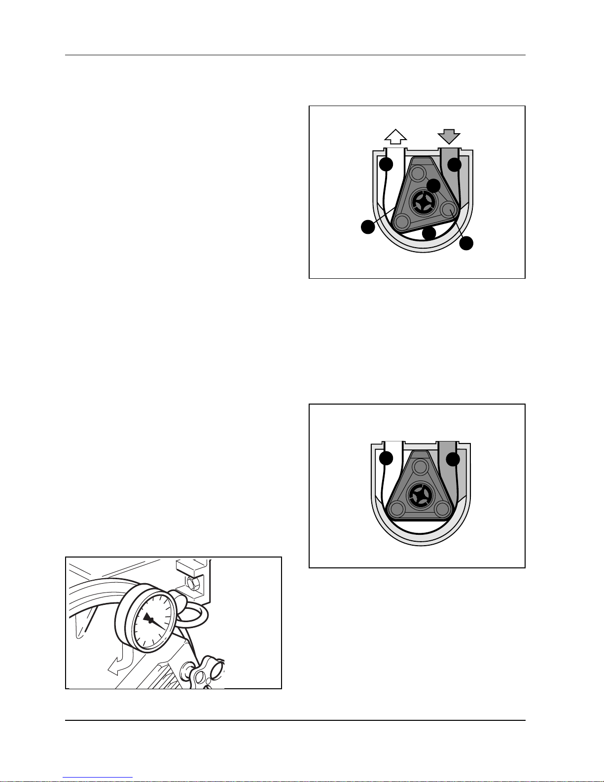
Fig. 3
1 Rotor
2 Support
3 Separating belt
Saugseite
1
2
3
Caution!
10
Peristaltic pumps Series M300 / T300
The sliding tube of the rotor enlarges the
volume of the suction area (4). At the same
time the pressure area (7) is decreased and
the air is forced out through a channel in
the pump cover.
Fig.4
Fig. 5
7
5
4
6
1
3
4
7
Rotor 1 rotates inside the separating belt 3,
which is tightly bolted to the housing. This
separates the suction area 4 from the inside
of the pump housing 5.
The support 2 (Fig. 3) is an elastomer part
and is installed in the pump section where
the hose is the most compressed.
At the same time this support protects the
pump housing against damage caused by
solid particles in case of a hose breakage.
In case of wear the support can be easily
replaced.
The separating belt 3 (Fig. 3) separates the
suction area from the inside of the pump
and protects the pumping hose. In case of
hose breakage it additionally protects the
rotor 1 (Fig. 3) against damage caused by
abrasive or coarse particle products. The
separating belt can be replaced by simply
unscrewing two screws.
The pump is filled with 1-2 litres of
lubricating fluid (glycerine or silicone),
which works as lubricant, barrier and
coolant.
The vacuum gauge connected with the
suction area (4, Fig. 4) not only shows the
present suction lift of the pump, but has the
additional function of a warning instrument
for possible defects. If the vacuum gauge
does not indicate a vacuum during
operation, the pump needs to be serviced
urgently.
Maintenance can be carried out without any
special tools.
1 Rotor
3 Separating belt
4 Suction area
5 Inside of housing
6 Hose chamber
7 Pressure area
4 Suction area
7 Pressure area
1 Vacuum gauge
11
Peristaltic pumps Series M300 / T300
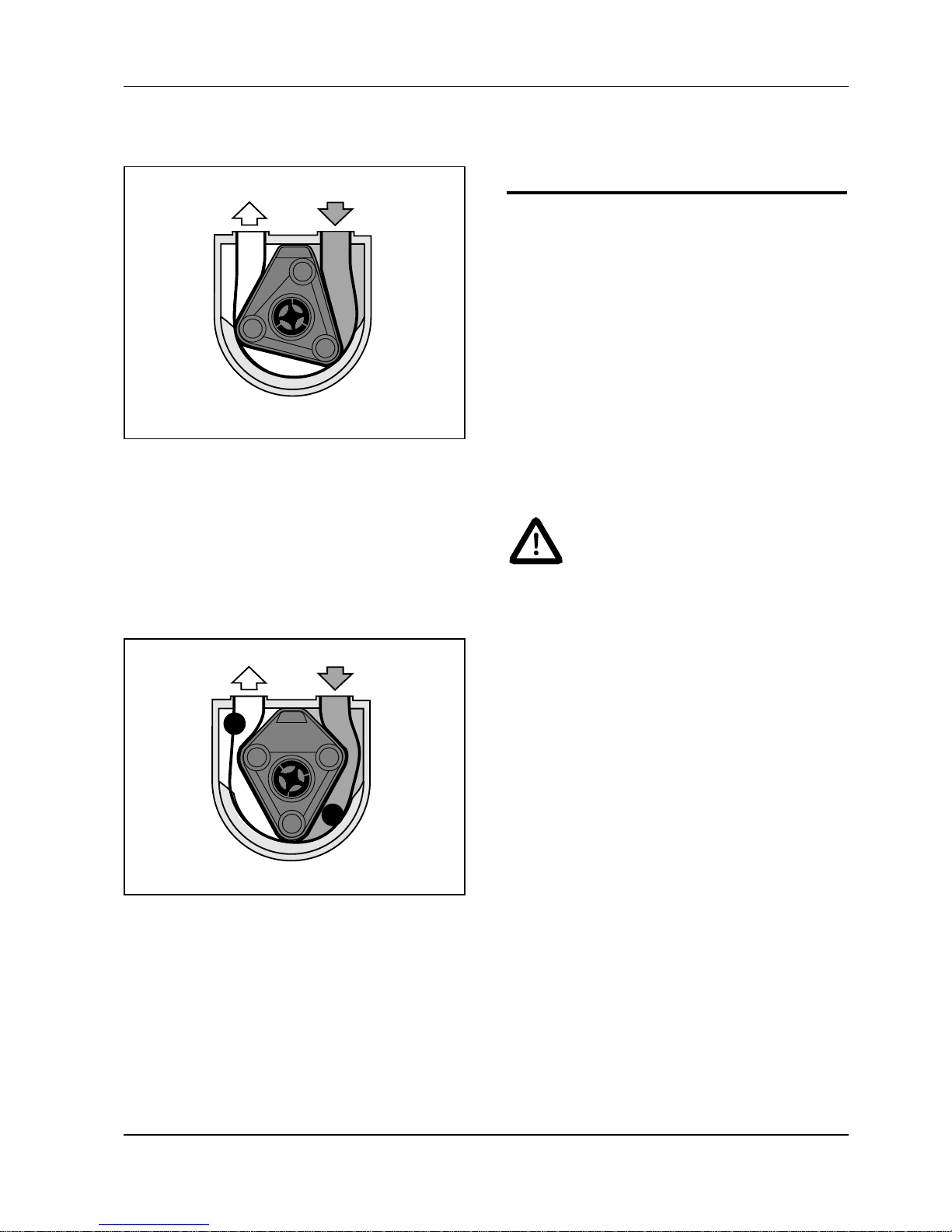
As the rotor rotates further the suction area
becomes bigger. The fast rotation of the
rotor generates a permanent vacuum of
down to -1 bar (Fig. 6). (33 fr. vacuum)
Fig. 6
Fig. 7
7
6
Since the hose chamber 6 remains
constant, the pressure area 7 is decreased
by the rotation of the rotor, which results in
a volumetric pumping process (Fig. 7).
2.0 Safety
2.1 General
Make sure that the pump is installed in
compliance with all applicable national
safety regulations.
Always observe all applicable accident
prevention instructions and implementing
regulations.
The following precautions must be applied
before performing maintenance work. If the
product to be pumped is a hazardous or
noxious substance, the system must be
neutralized and vented
Danger or burning
Depending on operating
conditions the pump may reach
temperatures too high to touch.
You should therefore switch off
the pump and let it cool down
before touching it.
■ Disconnect main drive unit and pump
from the electric power supply.
■ Depressurize the pump head.
■ It is not permitted to run the pump after
removing the pump cover. When
cleaning the pump manually make sure
that all necessary precautions have
been applied.
All incorrectly installed, unprofessionally
operated or insufficiently serviced
machines and pumps are potential safety
hazards.
Caution!
6 Hose chamber
7 Pressure area
 Loading...