

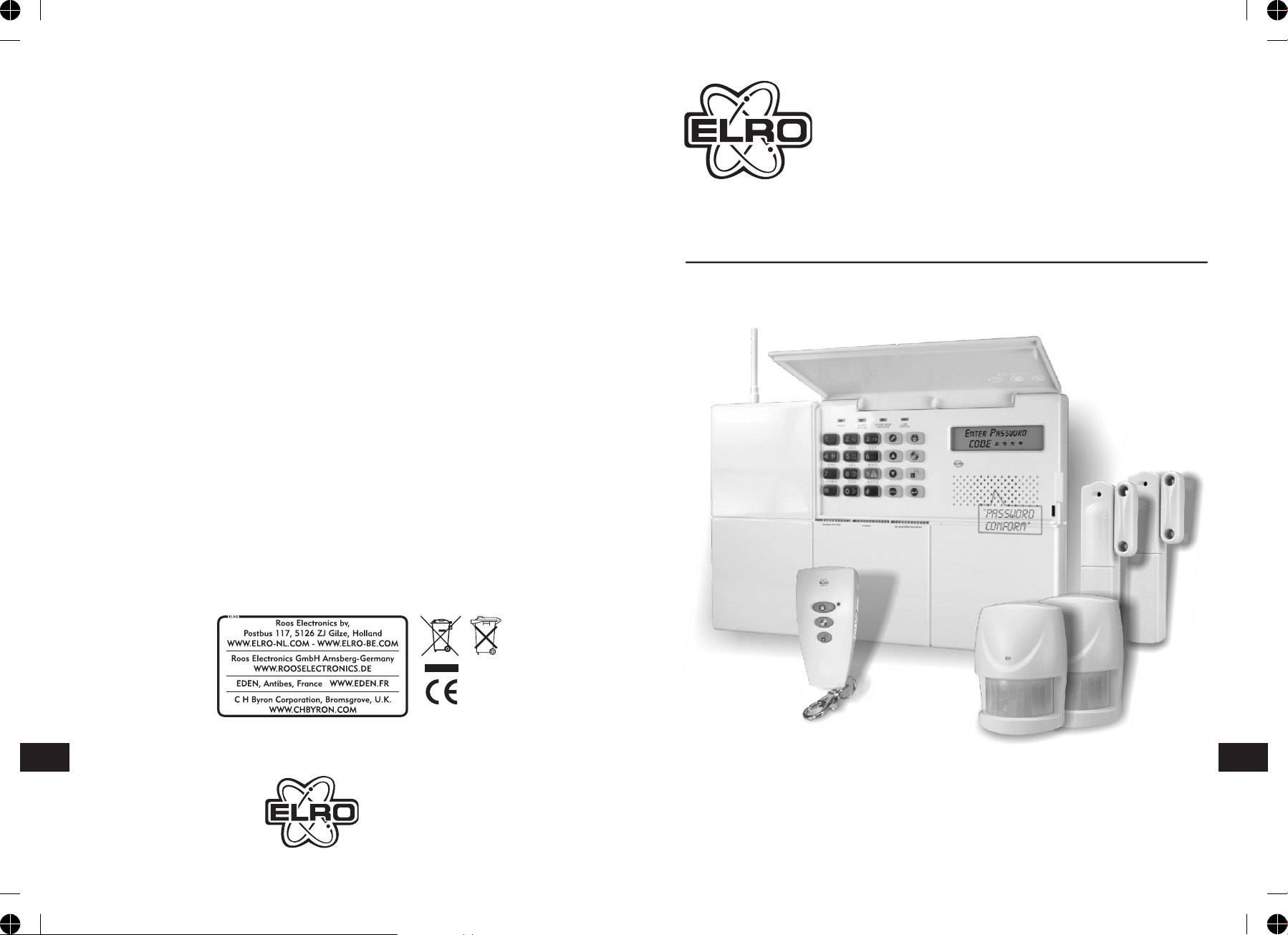
HA68
USER’S MANUAL
W W W . - N L . C O M
ENEN
MULTI-ZONE PROFESSIONAL ALARM SYSTEM
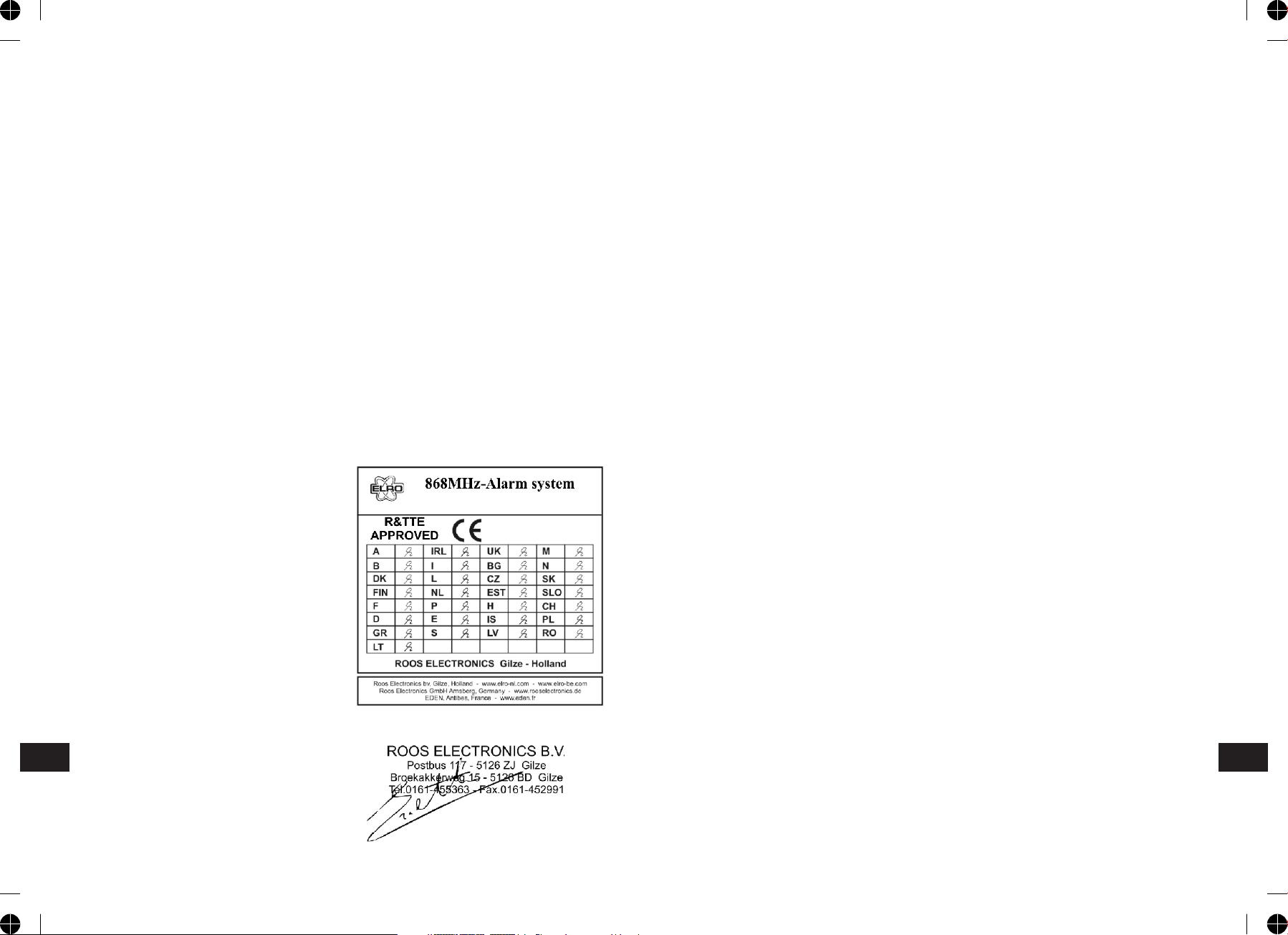
DECLARATION OF CONFORMITY
KONFORMITATSERKLARUNG
Company ROOS ELECTRONICS
Address, City Broekakkerweg 15, 5126 BD
PO Box 115, 5126 ZJGILZE
Country The Netherlands
Declares that the product:
Description Alarm system
Product number HA68, SA68P, SA68R, SA68M
Trade mark ELRO
Is herewith confirmed to comply with the requirements
set in the Council Directive on the Approximation of the
Member States relating to:
Electro Magnetic Compatibility Directive
(89/336/EEC) R&TTE Directive
(1999/5/EEC) LVD Directive (73/23/EEC)
Assessment of compliance of the product with the
requirements relating to EMC was based on the
following standards:
EN 301 489-1/-3:V1.4.1 (2002-08)
The requirements relating to Electrical Safety was based
on the following standards:
EN 600950-1:2001
The requirements relating RF was based on the
following standard:
EN 300 220-1 :V1.3.1 (2000-09)
EN 300 220-3:V1.1.1 (2000-09)
DECLARATION DE CONFORMITE
Société ROOS ELECTRONICS
Adresse/Ville Broekakkerweg 15, 5126 BD of
Boite postale 115, 5126 ZJ GILZE
Pays Pays-Bas
Déclarons que le produit :
Description Systeme d'alarme
Référence produit HA68, SA68P, SA68R, SA68M
Marque de commercialisation ELRO
Est certifié conforme aux exigences définies dans la
Directive du Conseil d'approximation des Etats Membres
suivante :
Compatibilité Electro magnétique
(89/336/EEC) Directive R&TTE
(1999/5/EEC) Directive Basse Tension (73/23/EEC)
L'évaluation de conformité du produit par rapport aux
exigences de Compatibilité Electro Magnétique a été
effectuée sur la base des normes suivantes :
EN 301 489-1/-3:V1.4.1
Les exigences Electriques surette ont été vérifiées par
rapport a la norme suivante
EN 60950-1 :2001
Les exigences radio ont été vérifiées par rapport à la
norme suivante :
EN 300 220-1 :V1.3.1 (2000-09)
EN 300 220-3: V1.1.1 (2000-09)
Firma ROOS ELECTRONICS
Adresse Broekakkerweg 15, 5126 BD of
Postbox 115, 5126 ZJ GILZE
Land Niederlande
Erklärung des Produktes:
Artikelbeschreibung Alarm system
Artikel-Nr.: HA68, SA68P, SA68R, SA68M
Markenname: ELRO
Hiermit bestätigen wir, um die Anforderungen aus den
Richtlinien des Rates über die Annäherung der
Mitgliedsstaaten zu befolgen, die Anerkennung
folgender Richtlinien:
Elektromagnetische Verträglichkeit (EMC)
(89/336/EEC) R&TTE-Anforderung
(1999/5/EEC) Niederspannungsrichtlinie (LVD)
(73/23.EEC
Die Bewertung des Produktes bezüglich der Anforderung
bezüglich EMC basiert auf den folgenden Standards:
EN 301 489-1/-3:V1.4.1
Die Anforderungen bezuglich Elektrisch Sicherheit
basiert auf den folgenden Standards:
EN 60950-1:2001
Die Anforderungen bezüglich RF basiert auf den
folgenden Standards:
EN 300 220-1 :V1.3.1 (2000-09)
EN 300 220-3:V1.1.1 (2000-09)
Authorized representative: Mr. Ad Netten
Date: 06.09.2005
ENEN

KIT CONTENTS
The Alarm System should contain the following components.
- 1 x LCD Control Panel
- 2 x Wirefee PIR Detector
- 2 x Wirefree Magnetic Contact Detector
- 1 x Remote Control
Also included:
- Power Supply Adaptor
- Telephone Connection Lead
- Installation & Operating Manual
- Fixing pack
- 2 x 6V/1.2Ahr Sealed lead acid battery
- 4 x 3.6V/950 mAhr 1/2 AA size
- 1 x 3V CR2032 Lithium
6V/1.2 Ahr
Sealed lead acid battery
(for Control Panel)
3.6v 1/2AA Size
Lithium battery (for
PIR Detector and
Magnetic Contact sets)
3V CR2032
Lithium cel (for
Remote Control)
IMPORTANT
Please check all items as mentioned above are included in the package.
SA68P
Wirefree PIR Detector
SA68M
Wirefree Magnetic
Contact Detector
HA68 Control panel
SA68R
Remote Control
ENEN
-1--64-

INTRODUCTION AND OVERVIEW
MULTIPLE USERS
The system allows for up to 5 Users and a Master User to be configured. This
allows the system Event Log to maintain a record of which users have armed
and disarmed the system. Each user will have a different Password. In addition a
4 second voice recorder facility enables the users name to be recorded for use
with the Latch-Key facility.
Only the Master User has access to the programming functions and is able to
configure the system.
Note: Each Remote Control Units on the system will be recorded.
SYSTEM ARMING
The system has a full ‘Arm’ and two ‘Partial Arm’ modes. ARM will ‘Arm’ all zones
while the ‘Partial Arm’ modes will only arm the zones that are enabled for the
particular partial arm mode.
For example:
The system could be configured such that during night time, ‘Partial Arm 1’
would arm only zones protecting the lower floor and outbuildings leaving the
upper floor free for movement without triggering the alarm.
During the day while the property is occupied ‘Partial Arm 2’ would arm only the
zones protecting the outbuildings. However, when the property is left unoccupied, the full ‘Arm’ mode will arm all zones to protect the entire property,
(i.e. upper and lower floors and outbuildings).
ZONES
The system incorporates 32 wireless Alarm Zones for the connection of the
system detectors that are used to independently monitor different areas of the
property. In addition to standard intruder protection, each zone may also be
configured to operate in one of four other modes:
- ‘Medical Help’ mode provides 24 hour monitoring of any panic switches
incorporated into the system.
- ‘24-hour Intruder’ mode provides 24 hour intruder protection for areas/zones
where continuous monitoring is required, (e.g. gun lockers).
- ‘Fire’ mode provides 24 hour monitoring of any Fire/Smoke detectors
incorporated into the system.
- ‘Intruder’ mode allows a zone to be monitored while the system is armed. If a
detector on a test zone is triggered an entry will be recorded in the Event Log
and an alarm will occur.
‘Panic’ mode provides 24 hour monitoring of any emergency being occurred.
Activation of any panic switch will immediately initiate a Full Alarm condition.
ENEN
-63--2-

BATTERIES
Before removing the battery cover on any device to replace the battery, ensure
that the system is put into Test mode to avoid initiating an Alarm.
In addition there is the facility to connect 4 hard wired zones to the Control
Panel, each of which is fully configurable with the same features as the wirefree
zones (1-32).
The specifications for replacement batteries are as follows:
Note: Rechargeable batteries should NOT be fitted.
At the end of their useful life the batteries should be disposed of via a suitable
Recycling Centre. Do not dispose of with your normal household waste. DO
NOT BURN.
The Rechargeable batteries contain Sulphuric Acid – DO NOT ATTEMPT TO OPEN
THE CASING.
ENTRY/EXIT DELAY
When the system is armed with the Exit-Delay enabled, no alarm signal from
any detector on an active zone will be able to initiate an alarm until the ExitDelay has expired. This enables the system to be armed from within the
property and allows time for the user to exit the property without triggering an
alarm. If the Exit-Delay is disabled then detectors on active zones will
immediately be able to initiate an alarm as soon as the system begins to arm.
The system Exit-Delay may be configured for between 10 to 250 seconds or
disabled completely.
If a detector on a zone with its Entry-Delay enabled is triggered, then an alarm
condition will not occur until the Entry-Delay period has expired. This allows time
for the user to re-enter the property and disarm the system before an alarm
condition occurs. Generally only the zones on the main entry route to the
property will be configured with an Entry-Delay. The remaining zones would be
configured with their Entry-Delay disabled allowing them to immediately initiate
an alarm a detector on the zone is triggered.
The Entry-Delay for each zone may be configured for between 10 to 250
seconds or disabled completely.
QUICK SET
The system may be fully armed in 5 seconds using the quick set facility,
overriding the programmed exit-delay.
This is useful for setting the system at night when the exit-delay warning beep
will be silenced after just a few seconds.
ZONE LOCKOUT
If a detector on an active zone is triggered while the system is armed an alarm
condition will occur. After the programmed alarm duration has expired the alarm
will stop. If a single zone initiates an alarm
condition more than three times then that zone will be ‘Locked Out’ and any
further alarm signals from that zone will be ignored until the system is
disarmed.
Note: The ‘Zone Lockout’ feature can be disabled if required.
EVENT LOG
The Control Panel incorporates a memory capable of storing the last 50 system
events. This enables the user to see which user has Armed/Disarmed the system
and if and when any alarms occurred. The time, date and details of the event
type will be recorded for each system event.
-3--62-
ENEN
CHIME
Chime is a low security facility for use when the system is Standby mode. If the
Chime feature is ON, and a detector on a zone that has its Chime function
enabled is triggered, the internal sounder will produce a low volume warning
tone. A typical use of the Chime function would be to warn that a door or
particular area has been accessed.
PIR DETECTORS
Under low battery conditions the LED behind the detector lens will flash when
movement is detected to indicate that the battery needs to be replaced.
Under normal battery conditions the LED does not illuminate unless the PIR
detector is in Walk Test mode.
VOICE DIALER
If the Voice Dialer is enabled and an alarm condition occurs, the system will call
for help using your recorded alarm messages and up to six telephone numbers.
When an alarm condition occurs, the telephone voice dialer (if enabled) will call
the first enabled number in the calling sequence and replay the recorded alarm
messages for the configured ‘Play Time’. The recipient must acknowledge the
message by pressing the button on their telephone keypad. If the call is
unanswered or an acknowledgment is not received then the next active number
in the dialing sequence will be called. The dialer will continue calling each
number in turn until either all numbers in the sequence have been dialed the set
number of times or the sequence is cancelled/acknowledged by the recipient.
DIGITAL DIALER
As an alternative to the Voice dialer the system may be configured to interface
with a central monitoring station.
LATCH KEY
When the system is disarmed the Latch-Key facility, if enabled, will call the first
latchkey phone number and replay the user message (recorded under user
setup) for the set ‘Play Time’. The recipient must acknowledge the message by
pressing the button on the telephone keypad. If the call is unanswered or
an acknowledgment is not received then the second latchkey phone number will
be called. The voice dialer will continue calling each number in turn until each
number has been dialed the set number of times or the sequence is
cancelled/acknowledged by the recipient.
For example, the latchkey facility is useful to inform parents that a child has
returned from school and disarmed the system.
MAGNETIC CONTACT DETECTORS
Under low battery conditions, when the Detector is activated the transmit LED
will be illuminated for approximately 1s as the door/window is opened.
Under normal battery conditions the LED will not illuminate as the Detector is
operated, (unless the Detector is in Test Mode with the battery cover removed).
MAINTENANCE
Your Alarm System requires very little maintenance. However, a few simple
tasks will ensure its continued reliability and operation.
CONTROL PANEL
The rechargeable batteries have a typical life of 3-4 years and need no
maintenance during this period, provided they are kept charged. The batteries
will be damaged if they are stored in a discharged state for long periods.
DETECTORS AND REMOTE CONTROL
The Detectors require very little maintenance. The batteries should be replaced
once a year or when a low battery status is indicated.
IMPORTANT: Should you, for any reason, have to completely power-down the
system (e.g. to move the system to a new premises) first put the system into
Test mode before removing the Control Panel cover and disconnecting the power
supply and backup batteries.
REMOTE SYSTEM CONTROL
It is possible to dial into the system via the connected telephone line to
interrogate the system status and to have basic control over the system, (e.g. to
Arm and Disarm the system). You may also activate the microphone on the
control panel to Listen-In to what is happening in the protected property.
TAMPER PROTECTION
All system devices (except the Remote Control Units) incorporate Tamper
protection features to protect against unauthorized attempts to interfere with
the device. Any attempt to remove the battery covers from any device (except
the Remote Control) or to remove the Solar Siren or Control Panel from the wall
will initiate an alarm condition (unless the system is in Test or Programming
modes), even if the system is Disarmed.
Remote Controls 1 x 3V CR2032 Lithium Cells
(or equivalent)
Magnetic Contact 1 x 3.6V 1/2 AA Size Lithium Cells
Detectors (or equivalent)
PIR Detectors 1 x 3.6V 1/2 AA Size Lithium Cells
(or equivalent)
-61--4-
ENEN

Press to Listen-In via the Control Panel Microphone.
Press to stop Listen-In
Note: Listen-in will be automatically cancelled after 5 minutes if not cancelled
manually.
Press to interrogate the system status. A message playing the latest
status can be heard.
7
#
8
JAMMING DETECTION
In order to detect any attempts to illegally jam the radio channel used by your
alarm system, a special jamming detection function is incorporated into the
Control Panel and Solar Siren. If this feature is enabled, and the radio channel is
jammed continuously for 30 seconds, when the system is armed, the Solar Siren
will emit a pre-alarm series of rapid bleeps for 3 seconds. If the jamming
continues for a further 10 seconds or more a full alarm condition will occur. In
addition if the system is jammed for more than three periods of 10 seconds in a
5 minute interval, this will also generate a Full Alarm condition.
Press to show the battery status.
Press to end the remote system control and hang up the Control Panel
line.
BATTERY MONITORING
All system devices continuously monitor their battery condition. The Control
Panel also monitors the battery condition of all PIR and Magnetic detectors. If
the battery level of any device drops below acceptable levels then its low battery
indication will be activated. In addition if any PIR or Magnetic Contact detector
has a low battery status it will be recorded by the Control Panel and a message
stored in the event log.
In the event of AC adaptor being disconnected from the Control Panel, the
Control Panel by consuming the DC rechargeable battery can sustain 2 days of
normal operation (under standby mode). However, the battery for that device
should be replaced as soon as possible.
Note: Before removing the battery cover on any device to replace the battery
ensure that the system is put into Test mode to avoid initiating a Full Alarm
condition.
The low battery indication for each system component is as follows:
CONTROL PANEL
During a period of mains supply interruption the Control Panel will be powered
by the rechargeable backup batteries. Under normal battery conditions the
Power LED on the panel will flash at 1s intervals. Under low battery conditions, if
setting to the voice dialer mode, a pre-recorded message will be played once
after one hour. If setting to the digital dialer mode, a radio signal will be emitted
to the central monitoring station right away and send the signal again after 4
hours.
9
#
The jamming detection features in the Control Panel and Solar Siren operate
independently.
The Jamming Detection circuit is designed to permanently scan for jamming
signals. However, it is possible that it may detect other local radio interference
operating legally or illegally on the same frequency. If it is planned to operate
the jamming detection feature we recommend that the system is monitored for
false jamming alarms for at least 2 weeks prior to leaving the Jamming
Detection function permanently enabled.
BATTERY MONITORING
In addition to the battery monitor and low-battery indicators in each device, the
Control Panel will also indicate a low battery status within any Passive Infra-Red
or Magnetic Contact Detector on the system using the Event log.
REMOTE CONTROL
When the Remote Control is operated under low battery conditions the transmit
LED will continue to flash after the button has been released.
Under normal battery conditions the LED will extinguish when the button is
released.
ENEN
-5--60-

PLANNING AND EXTENDING YOUR WIREFREE ALARM SYSTEM
The following example below shows a typical property incorporating the suggested positions for the Control Panel, PIR and Magnetic Detectors for optimum
security. Use this as a guide for your installation in conjunction with the recommendations contained in this manual for planning your intruder alarm system.
REMOTE SYSTEM CONTROL
If the Remote System Control facility is enabled, the Control Panel will answer
the call after the set number of rings and emit three beeps on the phone line to
prompt for a User Password to be entered using the telephone keypad.
A valid User Password will be acknowledged with one long beep. An incorrect
code will be acknowledged by two short beeps.
PIR-detector
Remote
Control
LOUNGE
PIR-detector
LCD
Control
Panel
Back Door
KITCHEN
HALL
Ground Floor GARAGE
DINNING
ROOM
Magnetic
Contact
Detector
PIRdetector
Magnetic
Contact Detector
SHED
PIRdetector
If the User Password is not entered within 30s or is entered incorrectly three
times then the Control Panel will automatically hang-up the line.
By pressing the button on the telephone keypad within 30 seconds, the
#
Control Panel will automatically hang-up the line.
Use with an External Answer-Phone:
If the Remote System Control is to be used in conjunction with an external
Answer-Phone then
The number of ‘one call ring’ for the Control Panel must be greater than that of
the External Answer-Phone, otherwise the Control Panel will always pickup the
call before the Answer-Phone.
To access the Remote System Control facility the Control Panel has a ‘double call
dial-in’ feature to enable the Control Panel to pick-up the phone call before the
external Answer-Phone cuts in. The ‘double call dial-in’ procedure is as follows:
1. Dial up the system and hang up after two rings.
2. Redial up the system within 28s as maximum (14s as minimum), the system
will pickup the phone after 1 ring.
3. Enter the User Password as normal.
The following functions may be access via the remote. The system will
acknowledge each signal with a single long beep.
Press to initiate ARM.
1
PIR-detector
Before attempting to install your Alarm System it is important to study your
security requirements and plan your installation.
The alarm system may be extended to provide even greater protection by fitting
additional PIR Detectors and Magnetic Contact Detectors as required.
Press to initiate Partial Arm 1.
Press to initiate Partial Arm 2.
Press to Disarm the system.
Press to turn the Siren OFF
2
3
4
5
.
Press to turn the Siren ON.
6
ENEN
-59--6-
CHIME
The Chime facility can only be operated with the system in Disarm mode.
Press to toggle the Chime facility between ON and OFF.
REMOTE CONTROL UNIT
Note: If the Chime is ON and the system is then armed the Chime will remain
ON after the system is disarmed.
MUTE
The Mute facility can only be operated with the system in Disarm mode.
Press to toggle the Mute facility between ON and OFF.
Note: If the Mute is ON, no voice guidance will be made during operation. If the
mute is OFF, voice guidance will be active. However, if ‘LINE STATUS’ LED
illuminates while the mute is OFF, there is no voice guidance will be available.
LATCH KEY
Press to access the latch key function for quick programming.
EVENT-LOG
The Event Log will store the last 50 system Arm, disarm, alarm and detector
Low Battery events. The Event Log will record the time, date and details for
each event. If when the system is disarmed the “ALARM MEM’ LED is flashing
and the panel beeps every 10s, this indicates that an alarm has occurred. To
cancel the LED and stop the beeping you must access the event log or press
to eliminate the flashing ‘ALARM MEM’ LED and the beeping as well.
To access the Event Log, (with the system in Disarm):
Press .
The Event-Log will automatically start scrolling through and displaying the event
data starting with the most recent event. The data for each event is shown on
two screens, each screen will be displayed for 5 seconds before moving on to
the next screen and then the next event.
Use the and buttons to manually scroll through the event log to the
required position as necessary.
Press to return to Disarm.
TELEPHONE LINE DETECTION
When setting to the voice dialer and If ‘LINE STATUS’ LED is flashing, it implies
bad telephone line connection or telephone network being out of order. Check
the telephone line and re-test it.
When setting to the digital dialer and if ‘LINE STATUS’ LED is flashing, it implies
two causes of failure. One is bad telephone line connection or telephone
network being out of order. The other cause of failure is derived from the
central monitoring station. Consult with the central monitoring station for help.
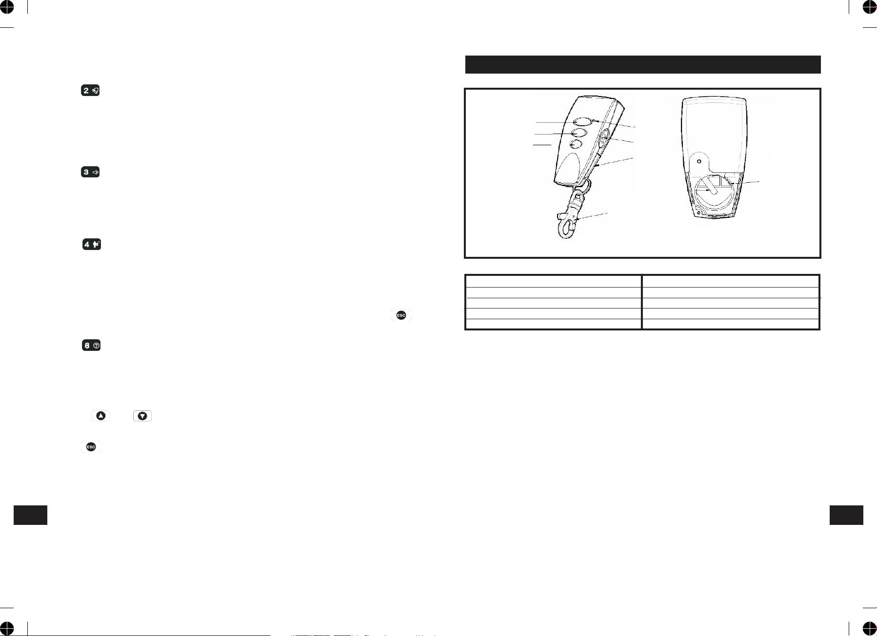
B
C
D
A
E
G
I
H
F
Front Back
A LED indicator F Key Chain Ring
B Arm G Battery Cover
C Partial Arm H Negative Polarity
D Disarm I Positive Polarity
E Panic Switch
The Remote Control Unit is used to Arm, Partial Arm and Disarm the system.
The Remote Control also incorporates a Panic switch. Activating the Panic switch
will immediately initiate a Full Alarm condition whether the system is Armed or
Disarmed, (unless the system is in Service, Test or Program mode).
The Remote Control adopts a CR2032 type Lithium cell which under normal
conditions will have typical life in excess of 1 year. Under normal battery
conditions the LED on the Remote control will only illuminate when a button is
pressed. However, under low battery conditions this LED will flash every time
the button is pressed. When this occurs the batteries should be replaced as
soon as possible.
SETTING THE REMOTE CONTROL
1.Remove the rear cover by undoing the small screw on the rear of the Remote
Control.
2.Insert the battery ensuring that the +v terminal faces upwards away from
the PCB.
ENEN
-7--58-

3. Replace the rear cover and fixing screw.
4. In order to communicate with the Control
Panel, the ID code of the Remote Control needs
to be learned by the Control Panel. By pressing
the button on the Remote Control will emit
Batterij
the ID code to the Control Panel instantly,
subject to the Control Panel being set at the
User Setup mode.
CONTROL PANEL
LOCATING THE CONTROL PANEL
When choosing a suitable location for the Control Panel, the following points
should be considered.
Remote Control:
Press the ‘DISARM’ button, .
Control Panel:
User Password
If the system is disarmed and the ‘ALARM MEM’ LED is flashing with the panel
beeping every few seconds, this indicates that an alarm condition has occurred.
Use the Event Log to find out and make a note of where the alarm occurred to
assist in tracing the cause of the alarm.
QUICK SET
To operate the quick set function and fully arm the system in 5s, overriding the
programmed exit delay. Press:
1. The Control Panel should be located in a position out of sight of potential
intruders and in a safe location, but easily accessible for system operation.
2. The Control Panel should be mounted on a sound flat surface to ensure that
the rear tamper switch on the Control Panel is closed when the Panel is
mounted. The Control Panel should be mounted at a convenient height of
between 1.5 and 2m and in a position where it will be seen each day.
Note: If small children are in the household, a further consideration should
be given to keeping the units out of their reach.
3. It is recommended that the Control Panel should be positioned such that the
Exit/Entry tone (emitted by the Control Panel) can be heard from outside the
property.
4. The Control Panel should be mounted within a protected area so that any
intruder cannot reach the Control Panel without opening a protected door or
passing through an area protected by a PIR detector when the system is
armed.
5. The Control Panel must be located within reach of a mains socket.
6. If the telephone based functionality is to be used then the Control Panel will
need connecting to a convenient telephone point.
Note: It is recommended that the telephone connection lead is not extended
beyond 5m before connecting to a telephone master or secondary outlet.
7. Do not locate the Control Unit closer than 1m to any large metallic object,
(e.g. mirrors, radiators, etc) as this may affect the radio range of the Control
Panel.
User Password
PANIC ALARM
A full Alarm condition can be immediately initiated
at any time (whether the system is Armed or Disarmed) in the event of threat
or danger by activating a Panic switch on either the Remote Control or the
Control Panel.
Remote Control:
Slide the Panic switch upwards.
Control Panel:
Press and hold the button for approximately 3 seconds.
The alarm will continue either for the alarm duration when the system will
automatically reset or until the system is disarmed.
TAMPER
If the battery cover of any device is removed or if the Siren or Control Panel are
removed from the wall then a Full Alarm condition will be initiated even if the
system is Disarmed. The alarm condition will continue either for the alarm
duration when the system will automatically reset or until the system is
Disarmed. The ‘ALARM MEM’ LED on the Control Panel will flash and the panel
will beep every few seconds to indicate an alarm has occurred.
Note: The Tamper protection facility on the Siren operates independently. If the
Tamper on the Siren is activated this will not be indicated at the Control Panel.
ENEN
-57--8-
ARM
The system can be set in ARM mode using either the Remote Control or the
Control Panel as follows:
Remote Control:
Press the ‘ARM’ button,
MOUNTING THE CONTROL PANEL
1. Undo the two captive fixing screws on top of the panel and open the cover.
The cover is hinged along the bottom edge.
2. Unclip and remove the two back-up batteries on either side of the panel.
Control Panel:
Press the Arm button followed by the User Password and then the Enter button:
User Password
By pressing , the programmed exit delay will be overrided to 5 seconds.
PART-ARM 1
The system can be set in PARTIAL Arm 1 mode using either the Remote Control
or the Control Panel as follows:
Remote Control:
Press the ‘PARTIAL ARM’ button, .
Control Panel:
User Password
By pressing , the programmed exit delay will be overrided to 5 seconds.
PARTIAL ARM 2
The system can be set in Partial Arm 2 mode using either the Remote Control or
the Control Panel as follows:
Remote Control:
Press the ‘PARTIAL ARM’ button twice, , .
Control Panel:
User Password
By pressing , the programmed exit delay will be overrided to 5 seconds.
3. Hold the Control Panel in position on the wall and mark the positions of the
four fixing holes. Remove the Panel and drill four 5mm holes and fit the
25mm Wall Plugs.
IMPORTANT: Do not drill the fixing holes with the Control Panel in position;
as the resulting dust and vibration may damage the Control Panel’s internal
components and invalidate the guarantee.
4. Fit two 18mm No.4 screws into the top holes until almost fully home and hang
the Control Panel over these screws using the two keyhole slots in the top
corners of the panel casing.
5. Route the cable from the Power Supply Unit up behind and on the right hand
side of the Control Panel and connect the plug to the DC power socket in the
panel. Ensuring that the cable is not trapped between the panel and the wall.
6. Fix the Panel to the wall using two 18mm No. 4 screws in the lower two fixing
holes in the panel and tighten the upper fixing screws until they just grip the
casing. Do not over tighten the fixing screws as this could damage or distort
the casing.
7. Ensure that the ‘Reset’ and the ‘Hard-Wired
Siren tamper detect’ jumper links are set in the OFF position.
8. Connect battery leads to both back-up batteries and refit batteries.
Battery 1 (left): Red lead to +ve battery terminal
Blue lead to –ve battery terminal
Battery 2 (right): Blue lead to +ve battery terminal
Black lead to –ve battery terminal
IMPORTANT: Take care when connecting battery leads to the batteries as
connecting incorrectly could damage the batteries or the Control Panel.
Note: The Power LED may flash to indicate that the unit is being operated
from the back-up batteries and that mains supply is not present.
DISARM
The system can be Disarmed using either the Remote Control or the Control
Panel as follows:
9. If fitted, remove the plastic film covering the LCD display and on the display
window on the cover.
10. Close the lid of the Control Panel and tighten the captive fixing screws.
11. Plug in and switch ON the Power Supply Unit, (the Power LED should
illuminate).
-9--56-
ENEN

12. If required, connect the Control Panel to the telephone line using the cable
supplied by inserting small RJ11 plug into socket marked LINE located on the
bottom edge of the Control Panel.
If the cable supplied is not long enough to reach a suitable phone point then
it will need extending using a coupler and extension lead (not supplied).
Notes:
Press to insert a 3.6s pause in the dialing sequence.
Press to move the cursor left.
Press to move the cursor right.
Note: If the Panel Tamper alarm sounds during the installation reset the
alarm by pressing:
, , on the Control Panel Keypad.
Upper Keyhole
Fixing Hole
Terminal Block
External Tamper
Switch Jumper
Link P51
Reset Jumper
Link P1
RS232 Interface
Earphone Socket
Power Supply
Jack Socket
+VE Terminal
(Red Lead)
Lower Fixing Hole
- VE Terminal
(Blue Lead)
Upper Keyhole
Fixing Hole
+VE Terminal
(Blue Lead)
- VE Terminal
(Black Lead)
Inside View of Control Panel
Press to delete the character under the cursor.
Press and hold to erase the entire phone number.
After programming all required phone numbers press to return to the top
level Latch.
OPERATING INSTRUCTIONS
When leaving the premises, the system must be Armed. However, before doing
so, check that all windows are closed and locked, all protected doors are closed
and PIR Detectors are not obstructed. Ensure that pets are restricted to areas
not protected by PIR Detectors.
The system has three arming modes, ARM, Part-Arm 1 and Part-Arm 2. The
Part-Arm modes allow for selected zones to be left in a Disarmed state while the
reminder of the system is Armed.
When the system is Armed (in any mode) the Control Panel will display the
arming mode and the status of the Latch Key for a few seconds. If enabled, the
system Exit-Delay will start and be counted down on the display. As the ExitDelay expires the Control Panel will beep, with the beep rate increasing in steps
as the delay expires. At the end of the Exit-Delay all active zones be Armed. By
this time the user must have left the property and closed the door.
If while the system is armed a detector on an active zone is triggered, if
enabled, the programmed Entry-delay for that zone will start and be counted
down on the display. As the Entry-Delay expires the Control Panel will beep, with
the beep rate increasing in steps as the delay expires. If the system has not
been disarmed when the Entry-Delay expires an alarm will occur. If however, the
Entry-Delay for the triggered zone has been disabled an alarm will occur
immediately.
At the end of the programmed alarm duration the Siren and Control Panel
alarms will stop and the system will automatically re-Arm.
-55--10-
ENEN

STATUS
This sets the users that the Latch Key facility will operate with. If set to ‘Partial’
the Latch Key will only operate with those users enabled in section ‘9-2 Set
Partial User’.
TESTING THE CONTROL PANEL & REMOTE CONTROL
1. Press , , to put the system into Test mode.
‘ TEST MODE – WALK TEST’ will be displayed.
Default setting: All OFF
Scroll through the menu until ‘9-1 Set Latch Key’ is displayed. The current
setting will also be displayed.
To change the setting press .
Scroll through the available options, (All on, All-off and Partial), until the
required setting is displayed.
Press to save and exit, or
Press to exit without saving.
PARTIAL USER SETUP
This allows controls over which users the Latch Key facility operates with when
set to ‘Partial’.
Default setting: OFF
Scroll through the menu until ‘9-2 Set Partial User’ is displayed and press .
Scroll through the menu until the required user number (1-5) to be configured is
displayed. The current status will also be displayed.
To change the setting press .
Press to enable the Latch-Key for the user, or
Press to disable the Latch-Key for the user.
After configuring all Users as required press to return to the top level Latch
Key Setup menu.
TELEPHONE NUMBERS
Scroll through the menu until ‘9-3 Set Latch Key TEL Number’ is displayed
and press .
2. Press to activate Walk Test. ‘Walk Test Waiting…’ will be displayed.
3. Press the ‘ARM’ button on the Remote Control. As the key is pressed the
Control Panel will beep and the type of the device and button will be shown
on the display.
Press the other buttons on the Remote Control in turn, as each button is
pressed the Control Panel will beep and show the button being pressed on the
display.
4. Test the range of the Remote Control by pressing the ‘DISARM’ button on the
Remote Control from in and around the property and from all locations where
you plan to install detectors. Check that the Control Panel acknowledges the
signal from the Remote Control each time the ‘DISARM’ button is pressed.
5. Press to return to the top level menu of TEST MODE.
PASSIVE INFRARED DETECTORS
PIR detectors are designed to detect movement in a protected area by detecting
changes in infra-red radiation levels caused when a person moves within or
across the devices field of vision. If movement is detected an alarm signal will
be emitted, (if the system is armed and the alarm zone active).
Note: PIR detectors will also detect animals, so ensure that pets are not
permitted access to areas fitted with Passive Infra-Red Detectors when the
system is armed.
The PIR Detector adopts a 1/2 AA size 3.6V Lithium battery which under normal
conditions will have typical life in excess of 4 years. When the battery level
drops, with the PIR in normal mode and the battery cover fitted, the LED behind
the detection window will flash upon detecting movement. When this occurs the
batteries should be replaced as soon as possible.
Scroll through the menu until the required telephone number (1-2) is displayed.
The current setting will also be displayed.
To change the number press .
Enter the new telephone number (32 digits max).
Press to save and exit, or
Press to exit without saving.
CHOOSING A MOUNTING LOCATION
The PIR Detector is suitable for mounting in dry interior locations only.
The recommended position for a PIR Detector is in the corner of a room
mounted at a height between 1.8 and 2m. At this height, the detector will have
a maximum range of up to 10m with a field of view of 110°, subject to the
position for the PCB being set in 5. The position of the PCB inside the PIR can be
set to 5 different positions to adjust the range of the detector. Setting the PCB in
position 3 will reduce the range to 7m approximately, with position 1 providing a
range of 5m approximately. The recommended position setting for the PCB is in
position 5.
-11--54-
ENEN

When considering and deciding upon the mounting position for the detector the
following points should be considered to ensure trouble free operation:
1. Do not locate the detector facing a window or where it is exposed to or facing
direct sunlight. PIR Detectors are not suitable for use in conservatories.
2. Do not locate the detector where it is exposed to ventilators.
3. Do not locate the detector directly above a heat source, (e.g. fire, radiator,
boiler, etc).
4. Where possible, mount the detector in the corner of the room so that the
logical path of an intruder would cut across the fan detection pattern. PIR
detectors respond more effectively to movement across the device than to
movement directly towards it.
Do not locate the detector in a position where it is subject to excessive
vibration.
5. Ensure that the position selected for the PIR detector is within effective range
of the system, (refer to System Installation and Operating Manual).
Note: When the system is armed, household pets should not be allowed into
an area protected by a PIR detector as their movement would trigger the PIR
and generate an alarm.
-53--12-

EXIT DELAY BEEP
This controls the warning beep which operates during the Exit Delay period
when Partial Arm 2 is initiated.
Default setting: ON
Scroll through the menu until ‘7-3 Exit Delay Beep’ is displayed. The current
setting will also be displayed.
To change the setting press .
INSTALLING THE PIR DETECTORS
Ensure that the system is in Test Mode.
1. Undo and remove the fixing screw from
the bottom edge of the PIR. Carefully
pull the bottom edge of the detector
away from the rear cover and then
slide down to release the top clips.
Rear Cover
Fixing screw
Press to enable the Exit-delay beep, or
Press to disable the Exit-delay beep.
Press to return to top level Partial Arm 2 Setup menu.
TIME & DATE SETUP
xx/xx/xx xxx
8-1 Date
dd/mm/yy
DD/MM/YY
PROGRAM MODE
Code:
8. Time & Date
8-2 Time
hh/mm/ss
HH/MM/SS
xx::xx:xx
Scroll through the menu until ‘8 TIME & DATE SETUP’ is displayed and
press .
Note: After configuring the Time and Date press to return to the top level
programming menu.
DATE
Scroll through the menu until ‘8-1 Date’ is displayed. The current setting will
also be displayed.
To change the setting press .
Enter the date in the format ‘dd/mm/yy’.
2. Carefully drill out the required mounting
holes in the rear cover using 3mm drill
2nd Mounting Hole
Positions
according to whether the unit is being
mounted in a corner or against a flat
wall.
Note: Using 1st mounting hole to fulfill
1st
Mounting
Hole Positions
corner mounting installation, while 2nd
mounting hole for flat wall installation.
3. Using the rear cover as a template,
mark the positions of the fixing holes
on the wall.
4. Fix the rear cover to the wall using the
two 18mm No.4 screws and 25mm wall
plugs, (a 5mm hole will be required for
the wall plugs). Do not over-tighten the
fixing screws as this may distort or
damage the cover.
Corner mounting
5. Configure the PIR detector as described below. Remember that on initial
installation that the device needs to be tested and should therefore be set in
Walk Test Mode.
6. Check that the detector PCB is located and set in the correct position to
provide the required detection range. To adjust the PCB position, simply slide
it up or down ensuring that the location legs are aligned with the required
position number marked on the board.
7. To refit the PIR detector to the rear cover and locate the clips in the top edge
into the rear cover. Push the lower edge of the detector into place and refit
the fixing screw in the bottom edge of the PIR to secure in position. Do not
over-tighten the fixing screws as this may damage the casing.
ENEN
Press to save and exit, or
Press to exit without saving.
-13--52-

SETTING THE PIR DETECTORS
Located on the PCB of the PIR Detector is a two-position DIP switch (SW2).
When conducting the Walk Test, ensure that the DIP switch SW2 is set as
follows:
SW2 DIP1 DIP2
ON
OFF
PROGRAM MODE
7. PARTIAL
ARM2
Code
DIP-switch
(SW2)
1. DIP1 of SW2 is used to configure the PIR Detector for walk test mode, which
allows the operation of the detector to be checked during installation without
triggering a Full Alarm.
ON Walk Test mode
OFF Normal mode
Note: On initial installation the detector should be set into Walk Test mode
ready for testing. Upon completion of Walk Test mode, set DIP1 of SW2 to
OFF for normal detection mode.
2. The PIR Detector incorporates an anti-false alarm feature designed to
compensate for situations where the detector may be affected by
environmental changes, (e.g. insects, air temperature, etc). This feature is
called “sensitivity detection” and may be selected for high or low detection.
The recommended setting is for high sensitivity detection. However, in cases
of extreme environmental problems or if unattributable false alarms are
experienced, it may be necessary to select low sensitivity detection.
Set the required sensitivity detection using DIP2 of SW2 as follows:
ON high sensitivity detection
OFF low sensitivity detection
Note: The higher the sensitivity detection the less movement will be
necessary before the PIR detector will trigger the alarm.
7-1 Exit Delay
xx xxx SEC
Select
ON->* OFF->#
7-2 Entry Delay
Beep: xxx
Select
ON-> OFF->#
7-3 Exit Delay
Beep: xxx
Select
ON->* OFF->#
Input (1-250) Secs
EXIT DELAY
Scroll through the menu until ‘7-1 Exit Delay’ is displayed. The current setting
will also be displayed.
Default setting: ON, 30s
To change the setting press .
Press to enable the Exit delay and enter the required exit delay period
(1-250s), or
Press to disable the Exit delay.
Press to save and exit, or
Press to exit without saving.
ENTRY DELAY BEEP
This controls the warning beep which operates during the Entry Delay period
when Partial Arm 2 is active.
Default setting: ON
Scroll through the menu until ‘:7-2 Entry Delay Beep’ is displayed. The current
setting will also be displayed.
To change the setting press .
Press to enable the Entry-delay beep, or
Press to disable the Entry-delay beep.
-51--14-
ENEN

EXIT DELAY
Scroll through the menu until ‘6-1 Exit Delay’ is displayed. The current setting
will also be displayed.
3. The setting of the DIP1 & DIP2 of SW2 can be distinguished from the LED
indication as follows:
Default setting: ON
To change the setting press .
Press to enable the Exit delay and enter the required exit delay period
(1-250s), or
Press to disable the Exit delay.
Press to return to top level Partial Arm 1 Setup menu.
ENTRY DELAY BEEP
This controls the warning beep which operates during the Entry Delay period
when Partial Arm 1 is active.
Default setting: ON
Scroll through the menu until ‘6-2 Entry Delay Beep’ is displayed. The current
setting will also be displayed.
To change the setting press .
Press to enable the Entry-delay beep, or
Press to disable the Entry-delay beep.
EXIT DELAY BEEP
This controls the warning beep which operates during the Exit Delay period when
Partial Arm 1 is initiated.
Default setting: ON
On/Off Selection DIP1 of SW2 DIP2 of SW2 Trigger reaction of LED
ON Walk Test mode High Sensitivity LED will be on once.
It implies high
sensitivity.
Low Sensitivity LED will flash twice.
It implies low
sensitivity.
OFF Normal mode High/Low LED does not light up.
Sensitivity
In summary, the setting of DIP1 & DIP2 of SW2 is concluded as below:
SW2 DIP1 DIP2
ON Walk Test Mode High sensitivity
OFF Normal Mode Low sensitivity
4. Connect the 1/2 3.6V Lithium battery to the battery spring.
Note: When the battery is connected, the LED behind the lens will flash for 23 minutes as warming-up duration until the PIR has stabilized when the LED
will then stop flashing and turn OFF.
5. In normal mode, remove the rear cover of the PIR detector. The Detector’s
LED will illuminate and the Control Panel should beep. It is because the
tamper switch fitted on the Detector has been activated.
Scroll through the menu until ‘6-3 Exit Delay Beep’ is displayed. The current
setting will also be displayed.
To change the setting press .
Press to enable the Exit-delay beep, or
Press to disable the Exit-delay beep.
PARTIAL ARM 2 SETUP
Scroll through the programming menu until ‘7. PARTIAL ARM 2’ is displayed
and press .
Note: After configuring Partial Arm 2 press to return to the top level
programming menu.
6. When the Detector is fully installed i.e. battery cover is refitted; the Detector
will not detect movement for approximately 2 minutes after each activation.
(This feature is present to conserve battery power and maximize the battery
life).
7. In order to communicate with the Control Panel, the ID code of the Detector
needs to be learned by the Control Panel. By pressing the tamper switch
located adjacent to the PCB on the Detector will emit the ID code to the
Control Panel instantly, subject to the Control Panel being set at the Zone
setup mode.
TESTING THE PIR DETECTORS
Ensure that the system is in Test Mode.
With the PIR detector set in Test mode and mounted in position on the wall,
allow 2-3 minutes for the detector to stabilize before commencing the Walk Test.
-15--50-
ENEN

1. Use the and buttons to scroll through the menu until ‘WALK TEST’
is displayed.
Press to activate Walk Test. ‘Walk Test Waiting…’ will be displayed.
2. Walk into and move slowly around the protected area, each time the detector
senses movement the LED behind the lens will flash. In addition, the Control
Panel will beep to indicate that the alarm signal has been received and the
identity of the zone that the detector is configured for will be displayed.
If necessary adjust the detection range by changing the mounting position of
the PCB within the PIR housing.
Note: In normal operation, the LED behind the PIR lens will not flash on
movement detection, (unless the battery is low).
If necessary re-adjust the detection pattern by changing the mounting
position of the PCB within the PIR housing.
3. Remove the back cover of the PIR detector. The Control Panel should beep
and display ‘PIR Detector Tamper’ to show that the detector’s tamper switch
has been activated.
4. Press to return to the top level menu of TEST MODE.
5. Reconfigure the PIR Detector for normal mode by setting DIP1 of SW2 to OFF
and refit in position.
Note: When the detector is fully installed i.e. battery cover is refitted; the
unit will not detect movement for approximately 2 minutes after each
activation. (This feature is present to conserve battery power and maximize
the battery life).
Default setting: ON
Scroll through the menu until ‘5-2 Entry Delay Beep’ is displayed.
The current setting will also be displayed.
To change the setting press .
Press to enable the Entry-delay beep, or
Press to disable the Entry-delay beep.
EXIT DELAY BEEP
This controls the warning beep which operates during the Exit Delay period
when Full Arm is initiated.
Default setting: ON
Scroll through the menu until ‘5-3 Exit Delay Beep’ is displayed. The current
setting will also be displayed.
To change the setting press .
Press to enable the Exit-delay beep, or
Press to disable the Exit-delay beep.
PARTIAL ARM 1 SETUP
PROGRAM MODE
Code:
6. PARTIAL ARM 1
MAGNETIC CONTACT DETECTOR(S)
The Magnetic contact consists of two parts; a Detector and a Magnet. They are
designed to be fitted to doors or windows with the Magnet mounted on the
opening part and the Detector mounted on the fixed frame. Opening the
protected door/window will remove the magnetic field, trigger the Detector and
generate an alarm condition, (if the system is armed and the alarm zone
active).
The Detector is powered by one 3.6V 1/2 AA size Lithium cells which under
normal conditions will have typical life in excess of 5 years. Under normal
battery conditions with battery cover fitted the LED on the Detector will not
illuminate when the Detector is triggered, (unless in test mode). However, under
low battery conditions this LED will be illuminated when the detector is
triggered. When this occurs the battery should be replaced as soon as possible.
6-1Exit Delay
xx xxx SEC
Select
ON->* OFF->#
6-2 Entry Delay
Beep: xxx
Select
ON-> OFF->#
6-3 Exit Delay
Beep: xxx
Select
ON->* OFF->#
Input
(1-250) Secs
Scroll through the programming menu until ‘6. PARTIAL ARM 1’ is displayed
and press .
Note: After configuring Partial Arm 1 press to return to the top level
programming menu.
-49--16-
ENEN

FULLY ARM SETUP
PROGRAM MODE
Code:
For double security, there are two tamper switches fitted on the Detector.
(FIGURE 2) Either removing the Detector from the protected door/window or
removing the battery cover will generate a full alarm condition.
The Magnetic Contact Detector is of self-contained wired Magnetic Contact. This
contact must be of a normally closed contact type with the contacts being
opened in order to generate an alarm condition.
5. FULLY ARM
5-1 Exit Delay
xx xxx SEC
Select
ON->* OFF->#
5-2 Entry Delay
Beep: xxx
Select
ON-> OFF->#
5-3 Exit Delay
Beep: xxx
Select
ON->* OFF->#
Input
(1-250) Secs.
Scroll through the programming menu until ‘5. FULLY ARM’ is displayed and
press .
Note: After configuring fully arm press to return to the top level
programming menu.
EXIT DELAY
Default setting: ON 30s
Scroll through the menu until ‘5-1 Exit Delay’ is displayed. The current setting
will also be displayed.
To change the setting press .
Press to enable the Exit delay and enter the required exit delay period
(1-250s), or
Press to disable the Exit delay.
Press to save and exit, or
Press to exit without saving.
Press to return to top level fully arm setup menu.
ENTRY DELAY BEEP
This controls the warning beep which operates during the Entry Delay period
when Full Arm is active.
CHOOSING A MOUNTING LOCATION
The Magnetic Contact Detector is suitable for mounting in dry interior locations
only.
Decide which doors/windows are to be protected by Magnetic Contact Detectors,
(usually the front and back doors as a minimum will have Magnetic Contact
Detectors fitted). Additional detectors may also be fitted where required to other
vulnerable doors or windows, (e.g. garage, patio/conservatory doors etc).
Note: Take care when fixing the Detector to a metal frame, or mounting within
1m of metalwork (i.e. radiators, water pipes, etc) as this could affect the radio
range of the device. If required, it may be necessary to space the magnet and
detector away from the metal surface using a plastic or wooden spacer to
achieve the necessary radio range.
INSTALLING THE MAGNETIC CONTACT DETECTORS
Ensure that the system is in Test Mode.
1. Undo and remove the fixing screw from
the bottom edge of the Detector.
Remove the battery cover by sliding
and lifting it off. (DO NOT use a screw
driver to lever the cover off).
2. Fit the 3.6V Lithium battery supplied,
Battery Cover
with the negative (-) towards the
battery spring.
3. Mount the Detector to the fixed part of the frame along the opening edge
opposite the hinges using either the double sided adhesive tape or screws
provided.
If fixing the Detector with screws; fit the Keyhole slot in the top of the
Detector over the head of the smaller pan-head screw. Secure the bottom of
the Detector using the 12mm countersunk head screw fitted within the
battery compartment. You will need to drill out the centre of the fixing screw
hole using a 3mm drill. Do not over tighten the fixing screws as this may
distort or damage the casing.
4. Fit the Magnet to the moving part of the door/window opposite the Detector
using the adhesive tape or 15mm fixing screws.
Ensure that the parallel gap between the Magnet and Detector is less than
10mm and that the arrow on the Magnet is pointing towards and aligned with
the mark on the Detector.
ENEN
-17--48-

5. If several windows need to be protected, remove the self-contained wired
supplied and adopt the wire according to the specifications as mentioned
below. This should be wired to the terminal block provided in the battery
compartment in series connection.
The wired contact should be connected using two core (24AWG) wire of
maximum length 1.5m.
A cable entry cut-out is available and adjacent to the terminal block.
6. Refit the battery cover.
Default setting: 6
Scroll through the menu until ‘:3 One Call Ring’ is displayed and press .
To change the setting press .
Enter the required number of ring (2-9).
Press to save and exit, or
Press to exit without saving.
SETTING THE MAGNETIC CONTACT DETECTORS
1. Located on the PCB of the Detector is a
two-position DIP switch (SW2).
Tamper Switch
DIP-switch (SW2)
Tamper Switch
2. DIP switches 1-2 are used to enable/disable the internal or external wired
magnetic contact. (FIGURE 3)
On/Off Selection DIP1 of SW2 DIP 2 of SW2
ON Internal on External on
OFF Internal off External off
INTERVAL OF RING FOR DOUBLE CALL
The interval of ring in each country vary greatly. Always add extra 2s to your
countries’ interval of ring.
Default setting: 13s
Scroll through the menu until ‘:4 Double Call Time’ is displayed and press
The current setting will also be displayed.
To change the setting press
Enter the required interval of ring (5s-15s).
Note: The duration of dialing the second call will vary depending on the interval
of ring you enter.
Enter 5s, it becomes 6-20s.
Enter 13s, it becomes 14-28s.
Enter 15s, it becomes 16-30s.
DIAL METHOD
This feature enables the telephone dialer to be configured for type of exchange
it is connected to.
Default setting: Tone/DTMF
Scroll through the menu until ‘4-4 Dial Method Setup’ is displayed. The
current setting will also be displayed.
To change the setting press .
Internal connection External wired connection
Scroll through available options, (Tone/DTMF and Pulse), until the required
setting is displayed and then
Press to save and exit, or
Press to exit without saving.
-47--18-
ENEN

REMOTE TELEPHONE CONTROL
Scroll through the manual until ‘:1 Remote TEL Control’ is displayed and
press .
If setting the DIP1 & DIP2 to ‘Off’, only the internal contact will be active.
When two contacts are in use for internal and external connection simultaneously, one activation will be counted if one of the contacts is opened; while
both contacts must be all close, the Detector will then be treated as close.
Default setting: OFF
To change the setting press .
Press to enable the Remote Telephone control, or
Press to disable the Remote Telephone control.
NUMBER OF DIALING CALL
This facility controls the number of dialing call via the connected telephone line.
Default setting: one call
Scroll through the manual until ‘:2 Remote Type’ is displayed and press .
To change the setting press .
Scroll through available options (e.g. one call & double call) until the required
setting is displayed.
ONE CALL
The number of ring for the Control Panel must be greater than that of the set
number of rings. By doing so, the Control Panel will answer the call and emit
three beeps on the phone line to prompt for a User Password to be entered
using the telephone keypad.
DOUBLE CALL
This feature is suitable for use when the fax or answer phone is connected to
Control Panel externally. The procedure is as follows:
1. Dial up the system and hang up after two rings.
2. Redial up the system within 28s as maximum (14s as minimum), subject to
the interval of ring being entered at 13s, the system will pickup the phone
after 1 ring.
Note: The maximum and minimum period for redialing up the system will
vary depending on the interval of ring you entered. Refer to ‘INTERVAL OF
RING FOR DOUBLE CALL’ for better comprehension.
3. Enter the User Password as normal.
NUMBER OF RINGS FOR ONE CALL
The number of rings for one call must be set within 2-9
3. If external contacts are wired to the Detector, set the DIP1 to ‘Off’ and DIP2
to ‘On’.
IMPORTANT: If external contacts are not connected, set the DIP1 to ‘On’ and
DIP2 to ‘Off’ for the detector to operate correctly.
4. In order to communicate with the Control Panel, the ID code of the Detector
needs to be learned by the Control Panel. By pressing the tamper switch
either located adjacent to the PCB or rear cover of the Detector will emit the
ID code to the Control Panel instantly, subject to the Control Panel being set
at the Zone setup mode.
TESTING THE MAGNETIC CONTACT DETECTORS
Ensure that the system is in Test Mode
1. Use the and buttons to scroll through the menu until ‘WALK TEST’
is displayed.
Press to activate Walk Test. ‘Walk Test Waiting…’ will be displayed.
2. Remove the battery cover by sliding off.
As the battery cover is removed the LED on the Detector will illuminate for
approx. 1 second to indicate that the tamper switch has been activated.
In addition, the Control Panel will beep to indicate that an alarm signal has
been received and ‘Magnetic Contact Tamper’ will be displayed.
3. Open the door/window to detach the magnet from the Detector. As the
magnet is parted from the detector the LED will illuminate for approx. 1
second to indicate that the Detector has been triggered. In addition, the
Control panel will beep to indicate that an alarm signal has been received and
the identity of the zone that the detector is set for will be displayed.
Note: In normal mode with the battery cover fitted, the LED on the detector
will not illuminate when the detector is triggered, (unless the battery is low).
4. If connected, operate the wired Magnetic Contact. As the contact is opened
the LED on the Detector should illuminate for 1 second to indicate that it has
been triggered and the Control Panel will acknowledge the alarm signal.
5. Refit the battery cover on the Detector.
ENEN
6. Press to return to the top level menu of TEST MODE.
-19--46-

EXTERNAL CONNECTIONS
The Control Unit incorporates a terminal block for connection of hard-wired
Zones (33-36), Siren or Telephone Dialer unit. The connection terminal block is
located inside the Control Panel behind the front cover.
CALL ATTEMPTS
This sets the maximum number of times that the dialer will attempt to contact
the central monitoring station.
If the dialer contacts to the central monitoring station once successfully, it will
stop dialing.
To access the terminal block Press
this puts the system into Test Mode and prevents an alarm occurring. Undo the
two fixing screws on the top edge of the Control Panel and open the front cover.
Before making any connections, ensure that the memory jumper link P1 is in
the ‘OFF’ position and then remove the DC power jack and disconnect one of the
back-up batteries.
Hardwire siren termina,there
is output voltagein OUT
position when alarm mode
(siren setting in ON mode)
DC power output terminal
V+ has power voltage output
Hardwired zone and tamper switches
should be Volt free and Normally
Closed, with the contacts opening in
order to initiate an alarm.
Note: Jumper link P51 should be
Relay output terminal,
accept other N.C. or N.O.
devices
fitted into the ON position only if the
external hardwired tamper circuit is
used, otherwise it must be in the OFF
Hard-wired zones for trigger
onput terminal, use standard
hard wire magnetic, there
are 4 sets of hard-wired
zones: T1(zone7), T2(zone8)
T3(zone9), T4 (zone10)
position.
After making your external
connections reconnect the power
supply and Back-up Battery. Then
close the Control Panel cover and
tighten the fixing screws on the top
edge of the Control Panel.
Battery power pack input,
option 12V DC battery input
to increase system stand by
life time
Negative tamper return,
normal close, system can be
detected once circuit close
Terminal Block
Default setting: 3
Scroll through the menu until ‘:3 Call Attempts’ is displayed. The current
setting will also be displayed.
To change the setting press .
Enter the required number (1-5).
Press to save and exit, or
Press to exit without saving.
ARM/DISARM BY USER
This determines when user makes a selection for disarming (Open) or arming
(Close) the system, an event code 401 is needed to be sent to the central
monitoring station. When setting to ‘On’, an event code 401 will be emitted,
setting to ‘Off’, an event code 401 won’t be emitted.
Default setting: Off
Scroll through the menu until ‘:4 ARM/DISARM By User’ is displayed. The
current setting will also be displayed.
To change the setting press .
Press to commence sending the event code.
Press to commence not sending the event code.
REMOTE SYSTEM CONTROL SETUP
Scroll through the manual until ‘4-3 Remote TEL Control Setup’ is displayed
and press .
Note: After completing the Remote Tel Control Setup, press to return to
the top level programming menu.
ENEN
-45--20-

DIGITAL DIALER SETUP
TESTING THE SYSTEM
Scroll through the menu until ‘4-2 Digital Dial Setup’ is displayed and press
Note: After completing the Digital Dialer Setup press to return to the top
level programming menu.
PHONE NUMBER
Scroll through the menu until ‘:1 Phone No:’ is displayed. The current setting
will also be display.
To change the setting press .
Enter the phone number (32 digits max. ranging from 0~9, *, #, ).
Press to save and exit, or
Press to exit without saving.
Notes:
Press to insert a 3.6s pause in the dialing sequence.
Press to move the cursor left.
Press to move the cursor right.
Press to delete the character under the cursor.
Press and hold to erase the entire phone number.
UNIT ID NUMBER
This helps central monitoring station set an ID number for the user whose
system is connected to their center.
Scroll through the menu until ‘:2 Unit ID No:’ is displayed. The current setting
will also be displayed.
To change the setting press .
Enter the ID number (4 digits max. ranging from 0-9, B, C, D, E, F)
Press to save and exit, or
Press to exit without saving.
INITIAL TESTING
As the system is initially installed it is recommended that each device is tested in
turn as it is installed, (refer to testing instructions for particular device).
TESTING AN INSTALLED SYSTEM
The Control Panel has a programmed test routine. You may test the system at
any time, however it is recommended that the system is tested at regular
intervals not exceeding 3 months.
With the system in Disarm Mode
Press This puts the system into Test Mode.
User Password
Use the and buttons to scroll through the menu and press to select
the displayed test function or sub-menu.
Note: After completing all required test functions, press to leave Test mode
and return to Disarm mode.
WALK TEST
Before commencing testing, please ensure that there is no movement in any PIR
protected area, all doors/windows protected by Magnetic Contact Detectors are
closed and that all battery covers and housings are correctly fitted.
Scroll through the top level Test Mode menu until ‘WALK TEST’ is displayed and
press . ‘Walk Test Waiting…’ will be displayed.
1. Trigger each detector on the system by either walking into a PIR protected
area or by opening a door/window protected by a Magnetic Contact detector.
As each detector is triggered the Control Panel will chime to indicate that an
alarm signal has been received and the identity of the zone that the detector
is configured for will be displayed.
2. Operate detector anti-tamper switches by opening the case of the device. As
the switches are operated the Control Panel will chime and zone name will be
displayed.
3. Activate each button on the Remote Control in turn. As each button is pressed
the Control Panel will chime and the button name will be displayed. (e.g.
‘REMOTE CONTROL DISARM’).
Press to exit Walk Test and return to the top level Test Mode menu
-21--44-
ENEN

ALARM TEST
Scroll through the top level Test Mode menu until ‘ALARM TEST’ is displayed and
press .
Scroll though the menu until the required alarm displayed and press to
operate the selected alarm for 5s.
Select ‘Wirefree Siren Test’ to operate the External Solar Siren.
Select ‘Hardwired Siren Test’ to operate the Control Panel Siren and external
hardwired Siren (if connected).
Select ‘Relay Test’ to operate the External hardwired
(N.O./N.C.) relay contacts.
Press to exit Alarm Test and return to the top level Test Mode menu.
WIREFREE SIREN SERVICE ON/OFF
Scroll through the top level Test Mode menu until ‘Wirefree Siren Service
ON/OFF’ is displayed and press .
TELEPHONE SETUP
:1 Set Tel No.
:1-1 TEL1
TEL2
TEL3
TEL4
TEL5
TEL6
Input Text:
Input No.
Delete.
:3 Play Voice
:3-1 MAIN+INTRUDER
Playing Playing
:3-3 MAIN+PANIC
:3-2 MAIN+FIRE
:3-4 MAIN
+MEDICAL
PlayingPlaying
PROGRAM MODE
Code:
4-1 Voice Dial
Setup
:4 Alarm Dial
xxxx
:5 TEL Confirm
xx
Input (1-6)
:6 Dial Round
xx
Input (1-9)
:7 Play Time
xxx SEC
50 SEC
70 SEC
90 SEC
110 SEC
This offers the flexibility of removing or changing siren’s battery. Wait for 10
seconds until ON/OFF duration has elapsed, then go ahead with fixing the siren
as desired.
VOICE DIALER TEST
Scroll through the top level Test Mode menu until ‘VOICE DIALER TEST’ is
displayed and press .
In order to test the voice dialer properly, the prerequisite is to set the telephone
number, record the message and enable the alarm dial in the programming
mode.
When testing is in progress, simply press to stop testing.
DIGITAL DIALER TEST
Scroll through the top level Test Mode menu until ‘DIGITAL DIALER TEST’ is
displayed and press .
In order to test the digital dialer properly, the prerequisite is to set the
telephone number and unit ID number in the programming mode.
When testing is in progress, simply press to stop testing.
RF ENVIRONMENT TEST
Scroll through the top level Test Mode menu until ‘RF Environment’ is
displayed.
If the ambient environment is full of radio frequency, an indication of ‘ENVIRON
POOR ’ will be shown on the LCD screen.
:2-1
Main Message
Select
Start->* Stop->#
:1 Phone No.
Enter Phone No.
:2. Unit ID No.
Enter Unit ID
:2 Stem
opnemen
Start->* Stop->#
4-2 Digital
Dial Setup
:3 Call Attempts:
:2-2
Intruder
Select
xx
Enter 1-5:
:4 ARM/DISARM
ON->* OFF->#
By User: xx
Select
ON->* OFF->#
:2-3
Fire
Select
Start->* Stop->#
:1 Remote TEL
Control
xx
Select
ON->* OFF->#
:4-1 TEL1
xx
Select
:4-2 TEL2
Select
ON->* OFF->#
Start->* Stop->#
4-3 Remote TEL
Control Setup
:2 Remote Type
Xx xxxx
One Call
Double Call
ON->* OFF->#
xx
:2-4
Panic
Select
:3 One Call
Ring: xx
Input (2-9) Ring
:4-3 TEL3
xx
Select
:4-4 TEL4
xx
Select
ON->* OFF->#
:2-5
Medical Help
Select
Start->* Stop->#
:4 Double Call
Time xx Sec.
Input (5-15) Sec.
:4-5 TEL5
xx
Select
ON->* OFF->#
:4-6 TEL6
Select
ON->* OFF->#
4-4 Dial
Method Setup
DTMF Pulse
xx
ENEN
-43--22-

Default setting: 1
Scroll through the menu until ‘:5 TEL Confirm’ is displayed. The current
settings will also be displayed.
To change the setting press .
Enter the required number (1-6).
Press to save and exit, or
Press to exit without saving.
DIAL ROUND
This sets the maximum number of times that the dialer will attempt to contact
each enabled telephone number in the call routing sequence.
Default setting: 3
Scroll through the menu until ‘:6 Dial Round’ is displayed. The current setting
will also be displayed.
To change the setting press .
Enter the required number (1-9).
Press to save and exit, or
Press to exit without saving.
ALARM MESSAGE PLAY TIME
This is the total time for which the alarm messages will be played & repeated
when a call made by the voice dialer is answered.
Default setting: 70s
Scroll through the menu until ‘:7 Play Time’ is displayed. The current setting
will also be displayed.
To change the setting press .
Scroll through the available options, (50, 70, 90 and 110s) until the required
setting is displayed.
DEFAULT SETTINGS
User Setup
Password Admin: 1234
User 1~5: Not
Programmed
Name Admin. User 1~5
Tel Remote Admin: ON
User 1~5: OFF
Record User
Message Not Programmed
Replay User
Message Not Programmed
Remoter Not Programmed
System Setup
Alarm Time 180s
Internal Siren ON
External Siren ON
Auto Report ON 12h
RF Jamming Detection OFF
Back Light 10s
Error Beep OFF, 30s
Alarm Relay ON until Disarm
Call Abort OFF
Key Tone ON
GSM Dialer OFF
Dialer Mode Voice
Wirefree Siren ON
Wirefree Keypad OFF
Zone Lock ON
Zone Setup (1-36)
Name No Name
Type Intruder
Chime Mode OFF
Entry Delay
Zone 1-36 OFF, 30s
Partial Arm 1 OFF
Partial Arm 2 OFF
Magnetic O/C Detector ON
Auto Report ON
Zone Status OFF
Zone Reset Not Programmed
Zone Siren ON
Telephone setup/ digital dialer.
Phone Not Programmed
Unit ID No. Not Programmed
Call Attempts 3
Open/Close by
User OFF
Telephone setup/remote telephone
control
Remote Telephone
Control OFF
Remote Type One Call
One Call Ring Ring 6
Double Call Time 13s
Dial Method DTMF
Fully arm setup
Exit Delay ON, 30s
Entry Delay Beep ON
Exit Delay Beep ON
Partial arm 1 setup
Exit Delay ON, 30s
Entry Delay Beep ON
Exit Delay Beep ON
Partial arm 2 setup
Exit Delay ON, 30s
Entry Delay Beep ON
Exit Delay Beep ON
Time & date setup
Date 01/01/05 Sat.
Time 12:00:00
Latchkey setup
Set Latch Key All OFF
Set Partial User OFF
Set Latch Key
Tel Number Not Programmed
Press to save and exit, or
Press to exit without saving.
Telephone Setup / Voice Dialer
Phone Numbers Not programmed
Record Voice Not Programmed
Play Voice Not Programmed
Alarm Dial All numbers
disabled
Tel Confirm Times 1
Dial Round 3
Play Time 70s
ENEN
-23--42-

RESET FACTORY DEFAULT
1. Press
, to place the system in Test Mode.
User Password
Note: After recording the message, press to stop the recorder and cancel
any remaining message time.
REPLAY ALARM MESSAGES
Scroll through the menu until ‘:3 Play Voice’ is displayed and press .
2. Undo the Control Panel cover fixing screws and open the cover.
3. Switch OFF the mains supply to the plug-in PSU Adaptor and remove the plug
from the DC power socket in the Control Panel.
4. Remove either back-up battery and disconnect the battery leads.
5. Set jumper link P1 to the ON position.
6. Reconnect the battery leads and replace the back-up battery in position.
Reconnect the PSU Adaptor plug to the DC power socket in the Control Panel
and switch On the supply to the PSU Adaptor.
7. As the Control Panel powers-up, ‘EEPROM RESET’ will be displayed while the
factory default conditions are restored to memory. Once the memory reset
has been completed ‘DISARM READY’ will be displayed. The Control Panel
will now be reconfigured with all factory default settings.
8. Reset jumper link P1 into the OFF position.
9. Close the Control Panel cover and refit the fixing screws.
PROGRAMMING INSTRUCTIONS
With the system in Disarm Mode.
Press , ,
Admin Password
The system is now in the Programming Mode
Use the and buttons to scroll through the programming menu.
Scroll through the available menu options until the required message type is
displayed.
a) Main + Intruder Messages
b)Main + Fire Messages
c) Main + Panic Messages
d)Main + Medical Help Messages
To replay the message press .
Press to return to the top level Voice Dialer setup menu.
CALL ROUTING
This feature controls which telephone numbers are enabled in the dialing
sequence and are dialed when the voice dialer is activated.
The current routing sequence is displayed on screen in the order of phone
numbers 1-6. An ‘X’ indicates the number is disabled and a ‘O’ indicates the
number is enabled in the routing sequence. e.g. A display = “00000x” indicates
a call sequence of phone nos.1,2, 3, 4 and 5, phone number 6 is disabled and
not called.
Default setting: all numbers disabled.
Scroll through the menu until ‘:4 Alarm Dial’ is displayed. The current settings
will also be displayed.
Scroll through the available menu options until the required telephone number
(1-6) to be configured is displayed. The current status will also be displayed.
To change the setting press .
Press to enable the number in the routing sequence, or
Press to disable the number in the routing sequence.
Press to select the displayed programming function or sub-menu.
Note:
After programming all required functions press to leave Programming mode
and return to Disarm mode.
TEL CONFIRM TIMES
This sets the number of acknowledged phone numbers required to stop the
voice dialer. For example if set to “2” then the dialing sequence will continue
until an acknowledgment is received from two different numbers, (e.g. Phone
No. 1 and Phone No. 3). The recipient must acknowledge the message by
pressing the button on their telephone keypad.
-41--24-
ENEN

TELEPHONE NUMBERS
Scroll through the menu until ‘:1 SET TEL NO.’ is displayed and press .
Scroll through the menu until the required Telephone number (1-6) is displayed.
The current setting of each telephone number will also be displayed.
USER SETUP
PROGRAM MODE
Code:
To change the number press .
Enter the required telephone number (32 digits. max.) by inputting 0~9, *, # .
Three available options - ‘Input Text’, ‘Input No.’ and ‘Delete’ can be chosen.
Scroll through available options, (Input Text, Input No. and ‘Delete), until the
required setting is displayed. To change the text, press .
When entering the text, press to toggle the number and character and
enter the required text.
Enter the required telephone number (32 digits. max.) by inputting 0~9, *, # .
When entering the number, press to insert a 3.6s pause in the dialing
sequence.
Press o save and exit, or
Press to exit without saving.
Notes:
Press to move the cursor left.
Press to move the cursor right.
Press to delete the character under the cursor.
Press and hold to erase the entire phone number or text.
RECORD ALARM MESSAGES
Scroll through the menu until ‘:2 Record Voice’ is displayed and press .
1. USER SETUP
:1 Password
xxxx
Enter Password:
CODE:
:2 Name
xxx
Enter Name:
1-1 Admin
SETUP
:3 TEL Remote
ON->* OFF->#
1-2 USER1 1-3 USER2
:4 Record
User Message
Select
ON->* OFF->#
Recording
Stop->ESC
Playing
xxxxxx
Select
1-4 USER3 1-5 USER4
:5 Replay
User Message
Playing….
Stop->ESC
:6-1 Learning ID
Learning..
Learning ok
Time Out
ID Duplicate
1-6 USER5
:6 Remoter
User Message
:6-2 Siren
xxx
Select
ON->* OFF->#
:6-3 Del Data
ON->* OFF->#
Scroll through the top level programming menu until ‘1. USER SETUP’ is
displayed and press .
Select
Scroll through the available menu options until the required message type to be
recorded is displayed.
a) Main Alarm message, (12 seconds max).
b) Intruder Alarm message, (4 seconds max).
c) Fire Alarm message, (4 seconds max).
d) Panic Alarm message, (4 seconds max).
e) Medical Help Alarm message, (4 seconds max).
To record a new message press .
Press to start the Voice Recorder. Once completed the recording will
automatically be replayed.
or
Press to exit without changing.
Use the and buttons to scroll through the menu until the required
user to be configured is displayed and press .
Note:
After configuring all required users press to return to the top level
programming menu.
ADMIN. & USERS 1-5
Default setting: not programmed
Scroll through the menu until the required User to be configured is displayed
and press .
ADMIN. & USER PASSWORD
Scroll through the menu until ‘:1 Password’ is displayed. For security
-25--40-
ENEN

purpose, the Admin. password won’t be displayed, only User password will be
shown on the display.
To change the setting press .
To change the setting press .
Press to enable Auto Report function, or
Press to disable Auto Report function.
Enter the new 4 digit Password and then
Press to save and exit, or
Press to exit without saving.
USER NAME
This enables each user’s name to be shown in the LCD screen once the system
is armed/disarmed by the particular user. The maximum memorized capacity for
each user name is 15 digits.
Scroll through the menu until ‘:2 Name’ is displayed.
To change the setting press .
Enter the user name by using the control panel’s keypad.
Press to save and exit, or
Press to exit without saving.
REMOTE SYSTEM CONTROL
This feature, if enabled, allows the system to be remotely controlled via the
telephone.
Scroll through the menu until ‘:3 TEL Remote’ is displayed.
To change the setting press
Press to enable the remote system control, or
Press to disable the remote system control.
RECORD USER MESSAGE
This enables each user to record a short 4s message for use with the latchkey
facility. e.g. “system disarmed by user-1”.
Scroll through the menu until ‘:4 Record User Message’ is displayed.
ZONE STATUS
This controls whether the detector is implemented on the zone.
Default setting: ON
Scroll through the menu until ‘:10 Zone status’ is displayed. The current
setting will also be displayed.
To change the setting press .
Press to enable the implementation of Detector on the zone, or
Press to disable the implementation of Detector on the zone.
ZONE RESET
This feature, if enabled, allows the deletion of the detector on the zone.
Scroll through the menu until ‘:11 Zone Reset’ is displayed.
Press to delete the setting of Detector on the zone, or
Press to keep the latest setting without changing.
ZONE SIREN
This decides whether all of the sirens connected to the Control Panel will sound
or be silent when the system is triggered.
Default setting: ON
Scroll through the menu until ‘:12 Zone Siren’ is displayed. The current setting
will also be displayed.
To change the setting press .
Press to enable the Sirens on the zone, or
Press to disable the Sirens on the zone.
To record a new message press .
Press to start the voice recorder, (max. duration: 4s) Once completed the
recording will automatically be played back, or
Press to exit without changing.
Note: After recording the message, press to stop the recorder and cancel
any remaining message time.
TELEPHONE SETUP
Scroll through the programming menu until ‘4-1. Voice Dial Setup’ is displayed
and press .
ENEN
Note: After completing the Telephone Setup press to return to the top
level programming menu.
-39--26-

Press to save and exit, or Press to exit without saving.
PARTIAL ARM 1
This controls whether the zone is active when Partial Arm 1 is armed.
REPLAY USER MESSAGE
Scroll through the menu until ‘:5 Replay User Message’ is displayed.
Press to replay the user message. Press to exit.
Default setting: OFF
Scroll through the menu until ‘6: Partial Arm 1’ is displayed. The current
setting will also be displayed.
To change the setting press .
Press to enable the Zone in Partial Arm 1, or
Press to disable the Zone in Partial Arm 1.
PARTIAL ARM 2
This controls whether the zone is active when Partial Arm 2 is armed.
Default setting: OFF
Scroll through the menu until ‘:7 Partial Arm 2’ is displayed. The current
setting will also be displayed.
To change the setting press .
Press to enable the Zone in Partial Arm 2, or
Press to disable the Zone in Partial Arm 2.
MAGNETIC CONTACT DETECTOR
This allows the control panel to be notified as to whether the magnetic contact
detector is active or inactive when the system is disarmed.
Default setting: ON
CODE LEARNING FROM REMOTE CONTROL
Each user has his own remote control. This enables the control panel to learn
the specific code from each remote control.
Scroll through menu until ‘:6 Remoter’ is displayed and press .
CODE LEARNING
Pressing button on the remote control will enable the control panel to learn
the ID code.
Scroll through the menu until ‘6-1 Learning ID’ is displayed.
Three possibilities would happen as follows:
Learning OK – the ID code was learned by the Control Panel successfully.
Time Out – the time involved for learning the ID code is 60s. During this
duration, fail to press the button on the remote control would result in
overdue programming.
ID Duplicate – the same ID code was learned by the Control Panel beforehand.
Use another remote control for code learning.
ALARM ALERT
This allows the user to decide whether the built-in siren in the control panel will
be activated when pressing the panic switch on the remote control.
Default setting: ON
Scroll through the menu until ‘6-2 Siren’ is displayed.
To change the setting press .
Scroll through the menu until ‘:8 Magnetic O/C Detector’ is displayed. The
current setting will also be displayed.
To change the setting press .
Press to enable the Magnetic Contact Detector, or
Press to disable the Magnetic Contact Detector.
AUTO REPORT
This feature, if enabled, allows the detector to be feed back the latest status to
the Control Panel periodically.
Default setting: ON
Scroll through the menu until ‘:9 Auto Report’ is displayed. The current setting
will also be displayed.
Press to enable the Siren, or Press to disable the Siren.
Note: If enabled, the operation of siren will depend on the respective setting on
‘System Setup’. If disabled, all of the sirens won’t be activated despite the
‘System Setup’ being enabled.
DELETE REMOTE CONTROL
In case of unexpected factors, this facility allows you to delete the remote
control setting from the Control Panel.
Scroll through the menu until ‘6-3 Del data’ is displayed.
To change the setting press .
Press to delete the remote control setting, or
Press to keep the same setting.
Press to return to the top level User-Setup menu.
-27--38-
ENEN

SYSTEM SETUP
Code:
PROGRAM MODE
Medical help
-used to provide 24 hour monitoring of elderly family members. A medical help
message will be dialed though either voice dialer or digital dialer depending on
what type of dial mode you selected.
2-1 Alarm Time
xxx Sec.
Enter 1-
60 (x10)s
2-13 Wirefree
Siren xxxx
1: Code Setup
DIP Sw:
12345678
H. Code: xxxxxxxx
2-3 EXT. Siren
ON->* OFF->#
2-2 INT. Siren
Select
ON->* OFF->#
2: Siren Working
xxx
Select
ON->* OFF->#
Select
2-4 Auto Report
Func. xxx xxH
Select
ON->* OFF->#
Input (03-72)
Hours
:1 Learning ID1
Learning..
2. SYSTEM SETUP
2-5 RF Jamming
Detection: xxx
Select
ON->* OFF->#
2-7 Error Beep
Xxx xxx Sec.
ON->* OFF->#
Input (01-25)
2-6 Back Light
xx Sec.
10s
20s
30s
60s
:2 Keypad 1Work
Select
ON->* OFF->#
Select
*10 Secs
2-8 Alarm Relay
Pulse 2s
Pulse 30s
Pulse 1m
Pulse 3m
Pulse 5m
ON until Disarm
2-14 Wirefree
Keypad xxxx
:3 Learning ID2
2-9 Call Abort
ON->* OFF->#
xx Sec.
Learning..
Select
2-10 Key Tone
ON->* OFF->#
:4 Keypad 2Work
2-11 GSM Dialer Link
ON->* OFF->#
xxx
Select
Select
ON->* OFF->#
xx
Select
2-12 Dialer Mode
xxxxx xxxxxx
Voice Dialer
Digital Dialer
2-15 Zone Lock
ON->* OFF->#
xx
Select
Panic
-used to provide 24 hour monitoring of any emergency being occurred.
Activation of any Panic switch will immediately initiate a Full Alarm condition.
Note: Panic, 24-hour Intruder, Medical help and Fire modes all operate on a 24
hour basis, (i.e. they are able to initiate Full Alarm condition at any time
irrespective of whether the system is Armed or Disarmed).
Default setting: ‘Intruder’
Scroll through the menu until ‘:3 Zone Type’ is displayed. The current setting
will also be displayed.
To change the setting press .
Scroll through available options until the required setting is displayed.
Press to save and exit, or
Press to exit without saving.
CHIME
This controls whether the Chime facility is available on the zone.
Default setting: OFF
Scroll through the menu until ‘:4 Chime Mode’ is displayed. The current setting
will also be displayed. To change the setting press .
Learning OK
Time Out
ID Duplicate
Learning OK
Time Out
ID Duplicate
Scroll through the top level programming menu until ‘2 SYSTEM SETUP’ is
displayed and press .
Note: After completing the system setup press to return to the top level
programming menu.
ALARM DURATION
Default setting: 180s
Press to enable the zone’s Chime facility, or
Press to disable the zone’s Chine facility.
ENTRY DELAY
Default setting: OFF 30 Sec.
Scroll through the menu until ‘:5 Entry Delay’ is displayed. The current setting
will also be displayed.
To change the setting press .
ENEN
Press to enable the zone’s Entry-delay and enter the required delay period
(10 to 250s) , or
Press to disable the zone’s Entry-delay.
-37--28-

CODE LEARNING
This enables the Control Panel to be learned the ID from each detector.
Scroll through the menu until ‘Learning ID’ is displayed and press .
Scroll through the menu until ‘2-1 Alarm Time’ is displayed. The current
setting will also be displayed. To change the setting press .
Enter the required alarm duration in units of 10s.e.g. enter 6 for a 60s alarm
duration (max setting 60, i.e. 600s/10mins).
Pressing tamper switch on the detector will emit ID code to the Control Panel
instantly.
Three possibilities would happen as follows:
Learning OK – the ID code was learned by the Control Panel successfully.
Time Out – the time involved for learning the ID code is 60s. During this
duration, fail to press the tamper switch on the detector would result in overdue
programming.
ID Duplicate – the same ID code was learned by the Control Panel beforehand.
Try again for code learning.
NAME
Default setting: ‘No name’
Scroll through the menu until ‘:2 Zone Name’ is displayed. The current setting
will also be displayed.
To change the setting press .
Scroll through available options until the required setting is displayed.
Press to save and exit, or
Press to exit without saving.
TYPE
Each alarm zone may be programmed to operate in one of 5 different modes
depending on the type of alarm function it is required to perform. The following
alarm types are available:
Intruder
- provides standard intruder monitoring with normal ARM and PARTIAL ARM
functions.
24 Hour Intruder
- used to provide 24 hour monitoring of areas requiring continuous security
protection even while the system is Disarmed, (e.g. gun lockers). Activation of
any detector on a security zone will immediately initiate a Full Alarm condition.
Press to save and exit, or
Press to exit without saving.
Note: Following initiation of a Full Alarm condition the External Siren will
continue to sound until either the system is disarmed; or the Control Panel
Alarm Duration Time expires.
Press to return to top level System Setup menu.
INTERNAL SIREN
Default setting: ON
Scroll through the menu until ‘2-2 INT. Siren’ is displayed. The current setting
will also be displayed.
To change the setting press .
Press to enable the Siren, or
Press to disable the Siren.
EXTERNAL HARDWIRED SIREN
Default setting: ON
Scroll through the menu until ‘2-3 EXT. Siren’ is displayed. The current setting
will also be displayed.
To change the setting press .
Press to enable the Hardwired Siren, or
Press to disable the Hardwired Siren.
AUTO REPORT
The associated detectors will emit a radio signal to the Control Panel every one
hour as an aknowledgement of proper operation. If within a certain period of
time, the control panel does not receive a radio signal from the detectors. This
feature, if enabled, allows the Control Panel to show an abnormal indication as a
reminder.
Fire
- used to provide 24 hour monitoring of any Fire/Smoke detectors fitted to the
system. Activation of any detector will immediately initiate a Full Alarm
condition.
-36-
Default setting: ON 12H
Scroll through the menu until ‘2-4 Auto Report Func.’ is displayed. The current
setting will also be displayed.
-29-
ENEN

To change the setting press .
ZONE SETUP
Press to enable the Auto Report function, or
Press to disable the Auto Report function.
JAMMING DETECTION
This feature controls the Control Panels RF jamming detection circuitry, which if
enabled, will continuously scan for radio jamming signals on the system
operating frequency.
Default setting: OFF
Scroll through the menu until ‘2-5 RF Jamming’ is displayed. The current
setting will also be displayed.
To change the setting press .
Press to enable Jamming Detection, or
Press to disable Jamming Detection.
CONTROL PANEL BACK LIGHT
This controls the time period that the backlight for the Control Panel display will
stay illuminated for after the last key is pressed.
Default setting: 10s
Scroll through the menu until ‘2-6 Back Light’ is displayed. The current setting
will also be displayed.
To change the setting pres s .
Scroll through available options, (10, 20, 30 and 60s) until the required setting
is displayed.
Press to save and exit, or
Press to exit without saving.
WARNING BEEP
When any abnormal conditions have occurred such as the system being
triggered or detectors’ low battery, the ‘ALARM MEM’ LED on the Control Panel
will be on accompanying warning beep as a reminder. This feature, if enabled,
allows the Control Panel to be emitted a warning beep periodically once
abnormal conditions is occurred.
:1 Learning ID
Learning
Learning OK
Time Out
ID Duplicate
:2 Zone Name
xxxxxxxxxxxxxx
No name
Front door
Back door
Patio door
Dining room
Living room
Lounge
Kitchen
Shed
Garage
Hall
Landing
Upstairs
Downstairs
Bedroom 1
Bedroom 2
Bedroom 3
Bedroom 4
Windows 1
Windows 2
Windows 3
PIR Detector
Magnetic Contact
FIRE/SMOKE
Panic/PA
Medical
PROGRAM MODE
Code:
:3 Zone Type
xxxxxxxxxxxxxx
Intruder
24 hour Intruder
Fire
Medical help
Panic
3. ZONE SETUP:
3-1 Set 1-36
Zone
Input (01-36)
Zone Number
:4 Zxx Chime
Mode xxxx
Select
ON->* OFF->#
:8 Magnetic
O/C Detector xxx
Select
ON->* OFF->#
:5 Zxx ENTRY
DELAY: XXX XXX
Select
ON->* OFF->#
Input
(01-25)*10Sec.
:9 Auto Report
Select
ON->* OFF->#
:6 Zxx
PARTIAL ARM 1:
Select
ON->* OFF->#
:10 Zone Status
Select
ON->* OFF->#
:7 Zxx
PARTIAL ARM 2:
Select
ON->* OFF->#
:11 Zone Reset
Select
ON->* OFF->#
:12 Zone Siren
Select
ON->* OFF->#
Scroll through the programming menu until ‘3. ZONE SETUP’ is displayed and
press .
Enter the zone number to be configured and press .
If when the system is disarmed the ‘ALARM MEM’ LED is flashing and the Control
Panel beeps periodically, this indicates that an alarm has occurred. To cancel
the LED and stop the beeping you must access the event log or press to
eliminate the flashing ‘ALARM MEM’ LED and the beeping as well.
The following configuration options are based upon configuring zone 1. Options
for all other zones (2-36) are identical except the zone number reference will
change according to the zone being configured.
-35--30-
ENEN

Scroll through the menu until ':3 Learning ID2' is displayed.
Default setting: OFF 30s
Three possibilities would happen as follows:
Learning OK - the ID code was learned by the Control Panel successfully.
Time Out - the time involved for learning the ID code is 60s. During this
duration, fail to press the button on the remote control
would result in overdue programming.
ID Duplicate - the same ID code was learned by the Control Panel beforehand.
Scroll through the menu until ':4 Keypad2 Work'
is displayed and press .
Press to enable the Wireless Keypad, or
Press to disable the Wireless Keypad.
ZONE LOCKOUT
This feature, if enabled, prevents a single zone from triggering an alarm
condition more than three times before the system is disarmed. However, if
disabled, there is no limit on the number of times a zone can trigger an alarm
condition.
Default setting: ON
Scroll through the menu until ‘2-15 Zone Lock’ is displayed. The current setting
will also be displayed.
To change the setting press .
Scroll through the menu until ‘2-7 Error Beep’ is displayed. The current setting
will also be displayed.
To change the setting press .
Press to enable Warning Beep and enter the required beeping interval in
units of 10s. e.g. enter 6 for a 60s beeping interval (max. setting 25, i.e. 250s)
Press to disable Warning Beep.
ALARM RELAY
This setting controls the operation period for the NO/NC hardwired output relay
contacts following an alarm condition being initiated.
If this is set to ‘ON until Disarm’ then the relay will latch and remain On until
the system is next disarmed.
Default setting: ON until Disarm
Scroll through the menu until ‘2-8 Alarm Relay’ is displayed. The current
setting will also be displayed.
To change the setting press
Scroll through available options, (2s, 30s, 60s, 180s, 300s and ON until Disarm )
until the required setting is displayed and then
Press to save and exit, or
Press to exit without saving.
Press to enable Zone Lockout, or
Press to disable Zone Lockout.
-34-
CALL ABORT
This feature, if enabled, will delay the activation of the telephone dialer following
an alarm for a period of approx. 30s to allow the system to be disarmed.
Default setting: OFF
Scroll through the menu until ‘2-9 Call Abort’ is displayed. The current setting
will also be displayed.
To change the setting press .
Press to enable Call Abort, or
Press to disable Call Abort.
ENEN
-31-

KEY TONE
This feature, if enabled, allows the Control Panel to be emitted a tone each time
the keypad is pressed.
Default setting: ON
learned by the Control Panel.
Scroll through the menu until ‘1:Code setup’ is displayed and press . Press
the Control Panel’s keypad 1-8 by selecting 0 or 1 respectively in turn. (1 means
the dip switch is set in ON position, 0 is set in OFF position).
Scroll through the menu until ‘2-10 Key Tone’ is displayed. The current setting
will also be displayed.
To change the setting press .
Press to enable Key Tone, or
Press to disable Key Tone.
GSM DIALER
This feature, if enabled, allows the Control Panel to be connected the GSM dialer.
Default setting: OFF
Scroll through the menu until ‘2-11 GSM Dialer’ is displayed. The current
setting will also be displayed
To change the setting press .
Press to enable GSM dialer, or
Press to disable GSM dialer.
DIAL MODE
This facility controls whether the internal telephone dialer operates with the
voice dialer facility or an external Remote Security Monitoring service.
Default setting: Voice Dialer
Scroll through the menu until ‘2-12 Dialer mode’ is displayed. The current
setting will also be displayed.
To change the setting press .
Scroll through available options, (Voice Dialer and Digital dialer) until the
required setting is displayed.
Press to save and exit, or
Press to exit without saving.
ENFORCEMENT FOR WIRELESS SIREN
Default setting: ON
Scroll through the menu until ‘2: Siren working’ is displayed. The current
setting will also be displayed.
To change the setting press .
Press to enable the Wireless Siren, or
Press to disable the Wireless Siren.
WIRELESS KEYPAD
This feature, if enabled, allows the Control Panel to be controlled wireless
keypad with ease.
Default setting: OFF
Scroll through the menu until ‘2-14 Wirefree Keypad’ is displayed. The current
setting will also be displayed and press .
Code Learning
Scroll through the menu until ‘:1 Learning ID’ is displayed.
Three possibilities would happen as follows:
Learning OK – the ID code was learned by the Control Panel successfully.
Time Out – the time involved for learning the ID code is 60s. During this
duration, fail to press the button on the remote control would result in
overdue programming.
ID Duplicate – the same ID code was learned by the Control Panel beforehand.
Press to save and exit, or
Press to exit without saving.
WIRELESS SIREN HOUSE CODE
Scroll through the menu until ‘2-13 Wirefree Siren’ is displayed and press .
Code Learning
The wireless siren has a row of 8 DIP switches. In order to communicate with
the Control Panel properly, the house code for the wireless siren needs to be
Scroll through the menu until is displayed and press .
Press to enable the Wireless Keypad, or
Press to disable the Wireless Keypad.
‘:2 Keypad1 Work’
-33--32-
ENEN
 Loading...