

Page 1
- 0 -
- 1 -
Directory
1. DVR FEATURE .................................................................................................................................... 3
2. OUTLOOK ............................................................................................................................................ 3
2.1 T
OP PANEL
........................................................................................................................................ 3
2.2 F
RONT PANEL
................................................................................................................................... 4
2.3
REAR PANEL
..................................................................................................................................... 6
2.4 L
ATERAL PANEL
................................................................................................................................ 7
2.5 R
EMOTE CONTROLLER
...................................................................................................................... 7
3. DVR INSTALLATION ........................................................................................................................... 7
3.1
INSTALL HARD DISK
........................................................................................................................... 7
3.2
CONNECT CAMERA AND MONITOR
..................................................................................................... 8
3.3 S
ENSOR CONNECTION
...................................................................................................................... 8
3.4
ALARM CONNECTION
......................................................................................................................... 8
3.5 M
OUSE CONNECTION
........................................................................................................................ 9
3.6 C
ONNECT POWER CORD
................................................................................................................... 9
4. DVR SYSTEM BOOT ........................................................................................................................... 9
5. DVR SETUP ....................................................................................................................................... 10
5.1 M
ENU DIRECTORY
.......................................................................................................................... 10
5.2 M
AIN MENU
..................................................................................................................................... 11
5.3 C
AMERA
.......................................................................................................................................... 11
5.4
RECORD
......................................................................................................................................... 12
5.4.1 Record Framerate .................................................................................................................. 12
5.4.2 Record Quality ....................................................................................................................... 13
5.4.3 Record Schedule.................................................................................................................... 13
5.5
ALARM
............................................................................................................................................ 14
5.5.1 Alarm Duration ....................................................................................................................... 14
5.5.2 Buzzer Duration ..................................................................................................................... 14
5.5.3 Event Rec Duration ................................................................................................................ 15
5.5.4 Sensor .................................................................................................................................... 15
5.5.5 Motion..................................................................................................................................... 15
5.6
AUDIO
............................................................................................................................................. 16
5.7 S
YSTEM
.......................................................................................................................................... 16
5.7.1 Password Setup ..................................................................................................................... 17
5.7.2 Hard Disk Setup ..................................................................................................................... 17
5.7.3 Time Setup ............................................................................................................................. 18
5.7.4 Event List ............................................................................................................................... 18
Page 2
- 2 -
5.7.5 Network Settings .................................................................................................................... 19
5.7.6 PTZ Setup .............................................................................................................................. 20
5.7.7 Screen Adjustment ................................................................................................................. 22
5.7.8 Key lock .................................................................................................................................. 22
5.7.9 Border..................................................................................................................................... 22
5.7.10 Auto sequence ..................................................................................................................... 22
5.7.11 Upgrade Firmware................................................................................................................ 22
5.8
SEARCH
.......................................................................................................................................... 23
5.9 L
ANGUAGE
...................................................................................................................................... 23
5.10
KEYPAD TONE
............................................................................................................................... 23
5. 11 E
XIT
............................................................................................................................................. 23
5.12 NTSC/PAL O
UTPUT SELECT
......................................................................................................... 24
6. RECORD ............................................................................................................................................ 24
6.1
START RECORDING
......................................................................................................................... 24
6.2
STOP RECORDING
........................................................................................................................... 24
6.3 R
ECORDING LENGTH
....................................................................................................................... 25
7. PLAYBACK ........................................................................................................................................ 26
8. BACKUP ............................................................................................................................................ 26
9. NETWORK ......................................................................................................................................... 27
9.1 H
ARDWARE INSTALL
........................................................................................................................ 27
9.2 S
ETUP IP ADDRESS OF
DVR............................................................................................................ 27
9.3 C
ONFIGURE IP ADDRESS OF
PC ...................................................................................................... 27
9.4 C
ONNECT PC TO
DVR—N
ET VIEWER
............................................................................................. 28
9.4.1 Install ...................................................................................................................................... 28
9.4.2 Program Interface .................................................................................................................. 29
9.4.3 Button Function ...................................................................................................................... 30
9.4.4 Local Recording ..................................................................................................................... 31
9.4.5 Play Local Recording ............................................................................................................. 32
9.5.
CONNECT PC TO
DVR — IE B
ROWSER
.......................................................................................... 35
10. SPECIFICATION .............................................................................................................................. 37
11. APPENDIX........................................................................................................................................ 38
11.1
SYSTEM CONNECT SKETCH MAP
................................................................................................... 38
11.2 F
ITTINGS COME ALONG WITH
DVR ................................................................................................ 38
- 3 -
1. DVR Feature
8 Channel BNC Camera Input.
1 Channel BNC Monitor Output.
Support Network: Static, DHCP.
USB port for Backup and Software Upgrade.
NTSC / PAL.
Video Loss Alarm.
Motion Detection with Area Setting.
PTZ Control with RS485 Port.
4 Sets NO/NC Sensor Input.
1 Alarm Output (2A 28VDC / 2A 125 VAC).
One SATA Hard Disk Interface, Support over 1.0TBytes.
Time Schedule Record / Sensor Triggered Record / Motion Triggered Record / Motion &
Sensor Triggered Record.
IR Remote Control unit.
True triplex functionality: Simultaneous Playback/Record/Network.
2. Outlook
2.1 Top panel
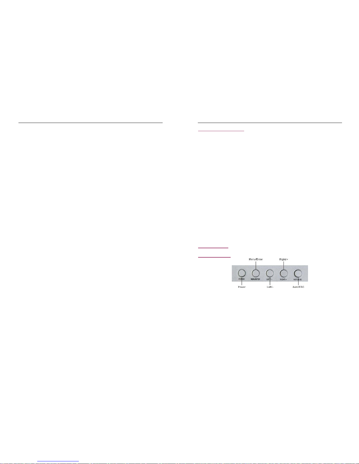
A. Function of the top panel
1. P
OWER ———Turn on / off the LCD monitor.
2. MENU/ENTER — Press the key to enter configuration of the LCD monitor
3. LEFT/- ———Move the prompt of the parameters on the screen or to reduce value.
4. RIGHT/+ ———Move the prompt of the parameters on the screen or to increase value.
5. AUTO/ESC ——— Press the key to exit the configuration of the LCD.
B. Menu Interface
Page 3
Page 4
Page 5
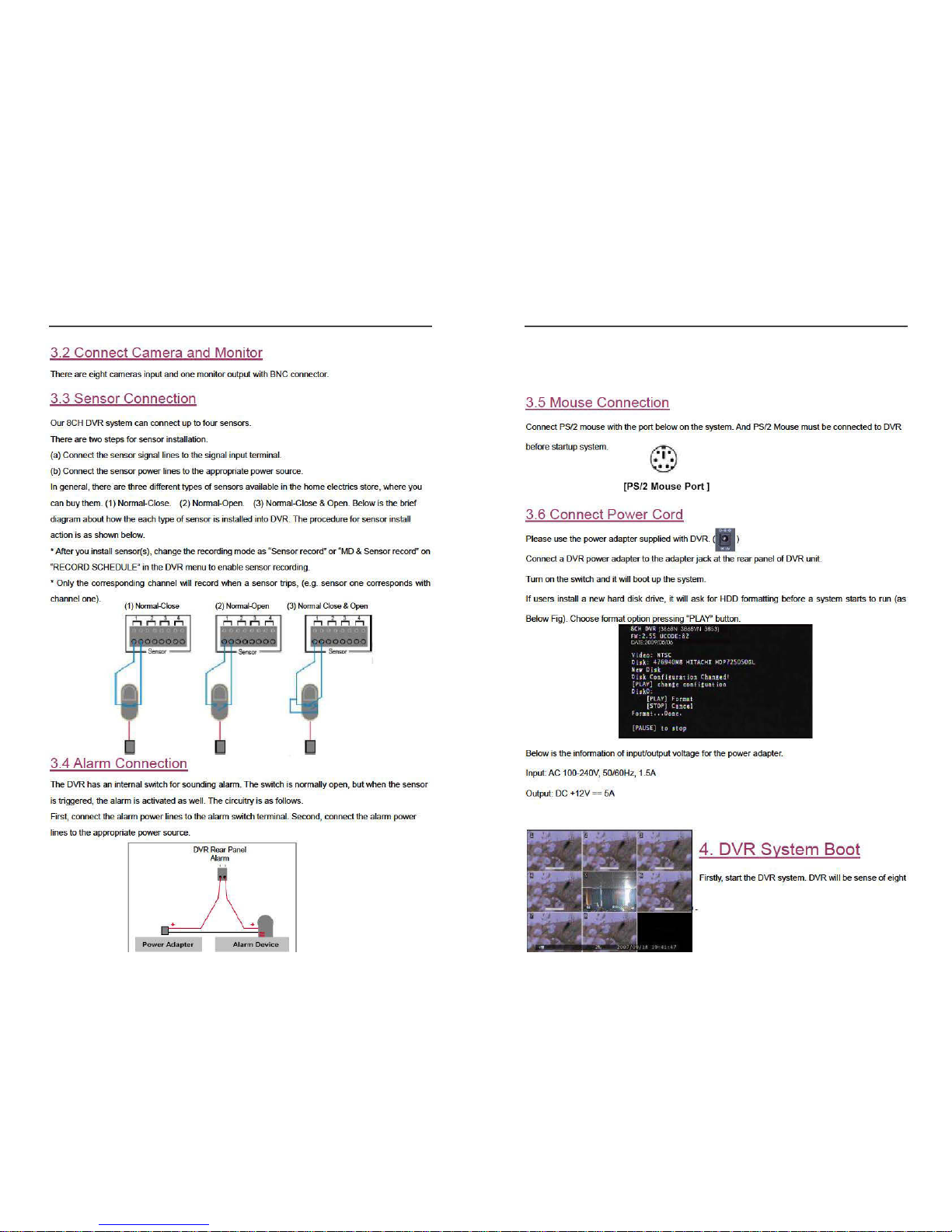
Page 6

Page 7
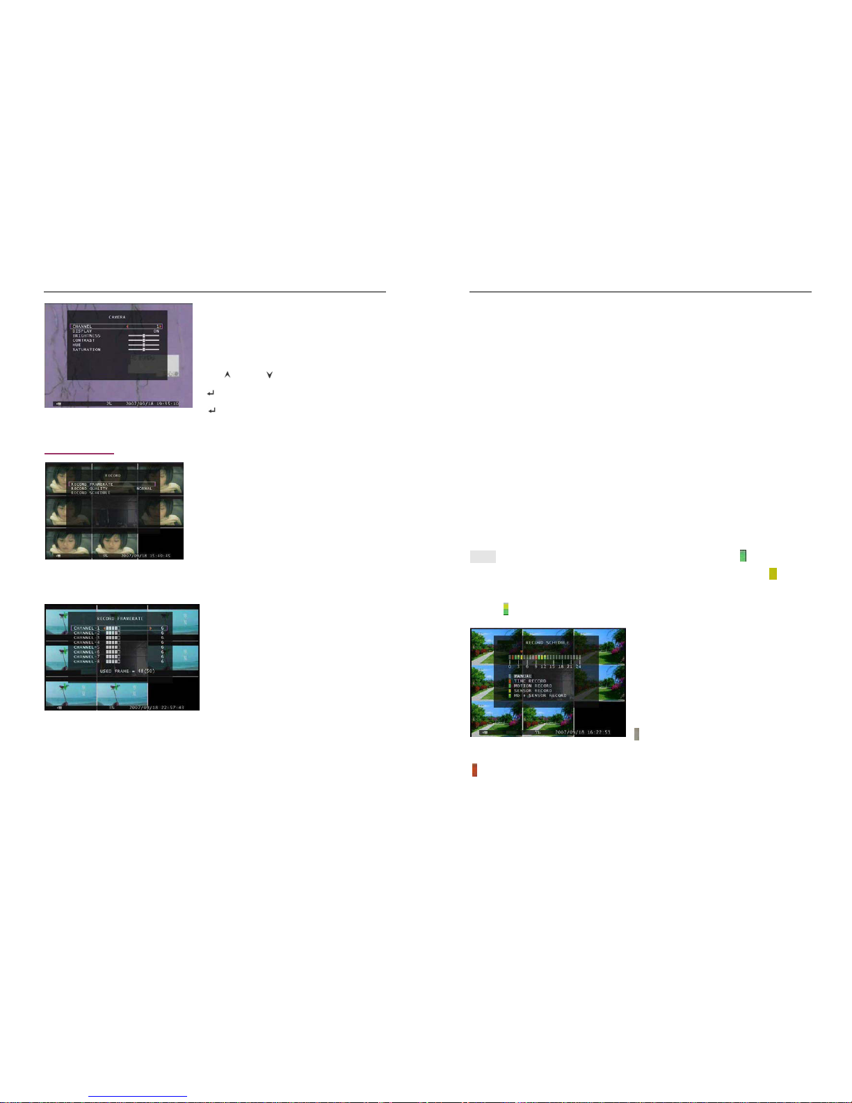
- 12 -
DVR system can display eight cameras and videos in
one picture. User can configure which camera to display.
If the order of “Display” for one channel is OFF, system
will display black on monitor.
Press「
Up」 or 「 Down」to move the prompt. Press
「 Select」 or 「REC」 to modify setting. The button
「 Select 」 can increase value and the button
「REC」can reduce value.
5.4 Record
Use this option to choose the channel (1,2,3,4,5,6,7,8) for
recording. Only selected channel will be recorded no
matter how many camera channels are displayed on the
screen.
5.4.1 Record Framerate
Record frame rate will affect the movement of object
i
n recorded video. More frames means more smooth
movement and cost more hard disk space.
Independent each channel frame rate adjustment is
possible.
For PAL video output format, system default value is 6
frames per second with each channel, which means
the system will record 48 frames per second with all channels. User can set frame rate as 1~25 frames
per second with each channel. The max value of total frames per second with all channels is 50 frames.
For NTSC video output format, system default value is 7 frames per second with each channel, which
means the system will record 56 frames per second with all channels. User can set frame rate as 1~30
frames per second with each channel. The max value of total frames per second with all channels is 60
- 13 -
frames.
If you make the record frame rate off, the channel won’t record.
Press button [SEL/EDIT] or hold a left mouse click button to click icon “►” to increase the record frame
rate for each channel. Press button “●” or hold a left mouse click button to click icon “◄” to decrease
the record frame rate for each channel.
5.4.2 Record Quality
There are three level of record quality, H
igh, Normal and Low. The higher the record quality is, the
higher the video image quality is when you playback. Higher quality cost more hard disk space. In
Chinese captions the best record quality is three, and the worst record quality is one.
Record frame rate, record quality and hard disk space will affect total record time of DVR system.
5.4.3 Record Schedule
User can setup video record method by time, sensor triggered, motion triggered or motion
&sensor triggered.
Notice: To start motion record, make sure the period that you intend to record is “ ” in the “record
schedule” menu. To start sensor record, make sure the period that you intend to record is “
”in the
“record schedule” menu. And to start motion & sensor record, make sure the period that you intend to
record is “
”in the “record schedule” menu.
Press 「Up」 or 「Down」or move the mouse to move
the prompt, and press「SEL/EDIT」or single left-click
to select video record method. User can press the
button 「ALL」or hold a left mouse button to click the
time period(24:00:00) to set up the same record
method during the whole time.
“
”: Manual Record(System Default). No record will
be made for this time period if user can’t activate manual recording.
“ ”: Time Record. The time period with a red bar will activate continuous recording mode (Time record)
unless there is any manual stopping during recording during that time.
Page 8
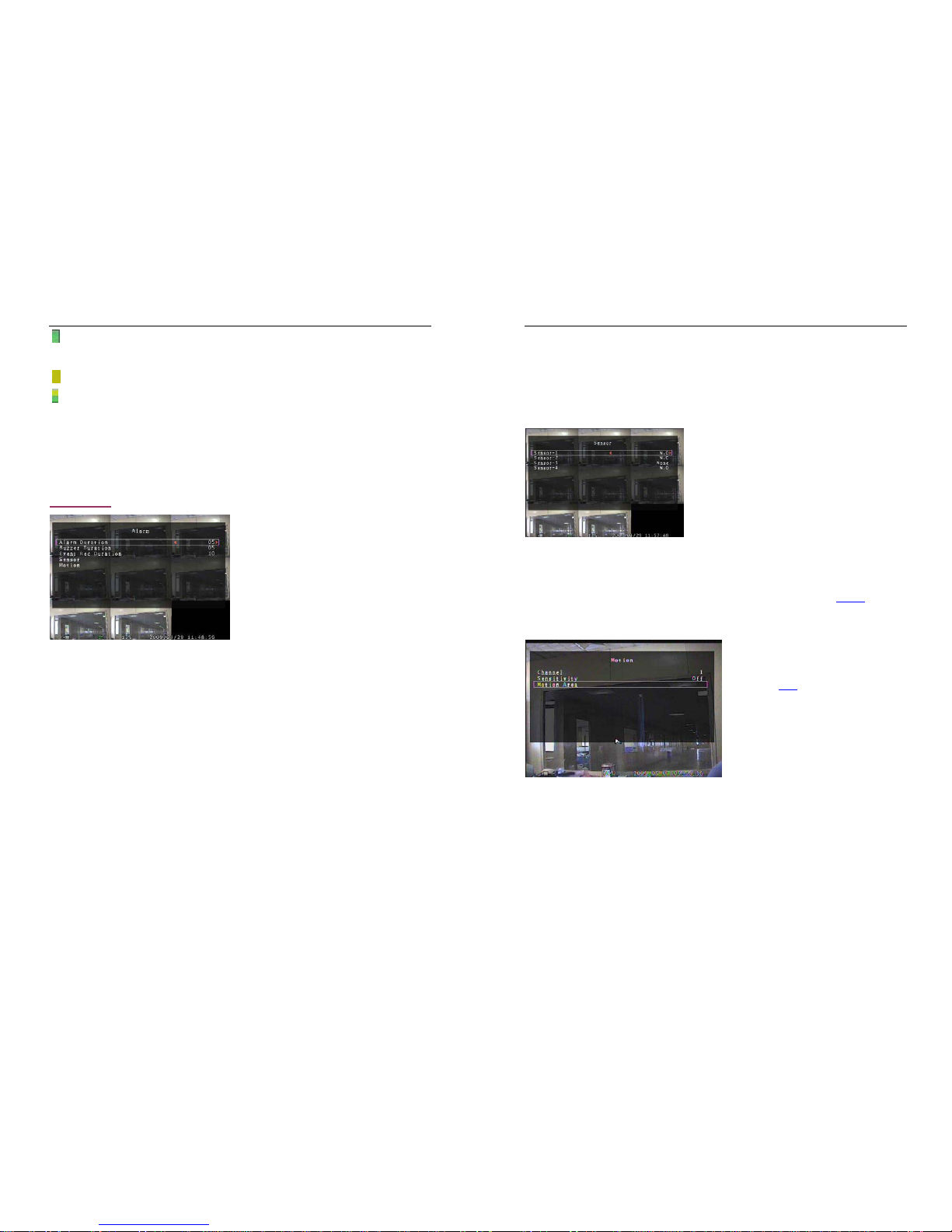
- 14 -
“ ”: Motion Triggered. The time period with a green bar for built-in motion recording(MD). (See also the
following chapter “MOTION DETECTION”)
“ ”: The time period with yellow bar will activate external sensor recording.
“ ”: The time period with half-yellow and half-green bar will activate the combination of built-in motion
(MD) recording and external sensor (Sensor) recording. (See also the following chapter “SENSOR”)
Cooperate with many kinds of external sensor equipment like PIR, Gas sensor. DVR will not record
video until external sensor was triggered and output signal to notify DVR during this specified period of
time.
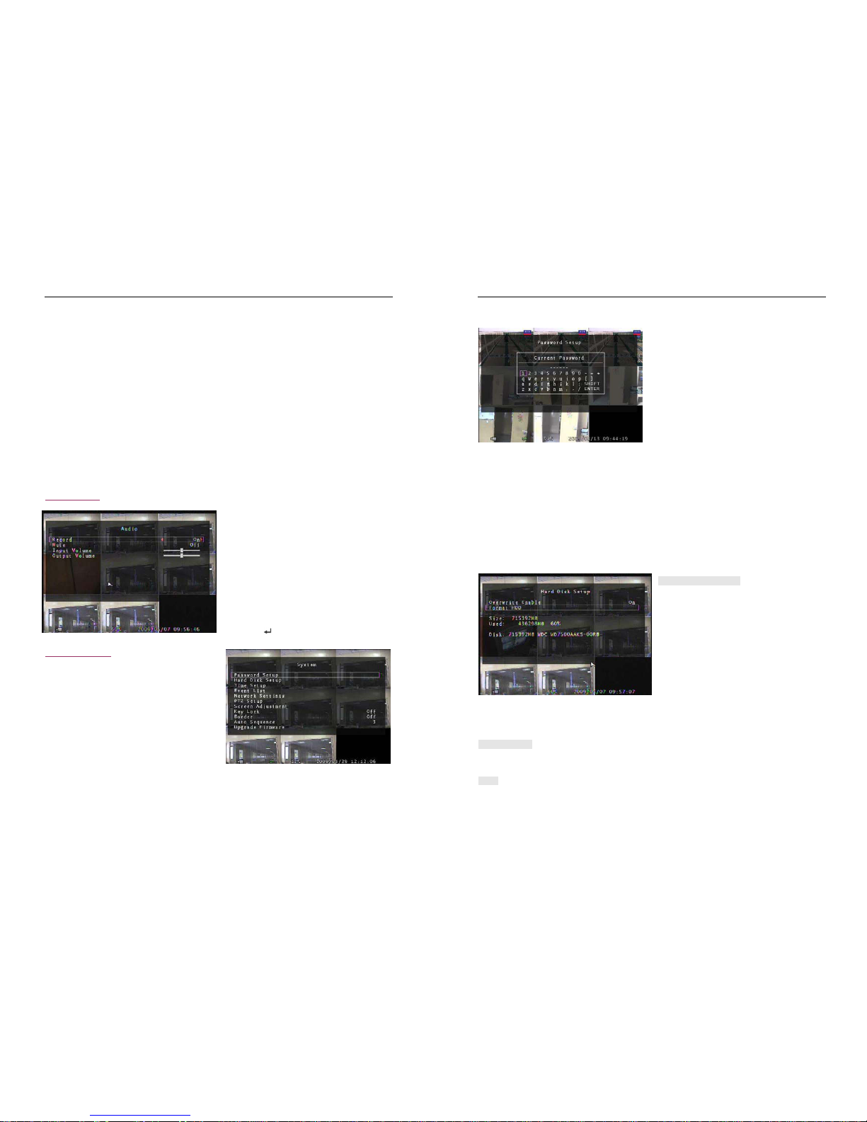
5.5 Alarm
Using [SEL/EDIT] button or hold a left mouse button
to click icon “◄” / “►”, adjust parameters of each
option.
5.5.1 Alarm Duration
It sets the alarm duration time (in seconds) after alarm is activated.
Va
lue at “05、10、15、20、25、30、CONT、OFF”(in seconds). Default at “OFF”.
By changing the value in the ALARM DURATION, you can adjust how long the alarm will last in
seconds. The alarm device should be installed.
5.5.2 Buzzer Duration
It sets the buzzer duration time (in seconds) after motion detection alarm is activated.
V
alue at “05、10、15、20、25、30、Cont、Off”(in seconds). Default at “Off”. When “buzzer duration” is
“Cont”, the buzzer will work continuously. When “Buzzer Duration” is “Off”, all the buzzers will be shut
off.
- 15 -
5.5.3 Event Rec Duration
It sets the record time of duration (in seconds) after motion recording is activated.
Value at “05、10、15、20、25、30”(in second).
5.5.4 Sensor
Activate / deactivate or choose the type of sensor. There
a
re three different modes for sensor setting:
N.C
(NORMAL-CLOSE)
&
N.O
(NORMAL-OPEN) &
None.
Select “None” to deactivate sensor recording or if there
was no sensor installed in DVR system.
It depends on what type of external sensor you use. If
sensor’s output is N.O, then select N.O mode in DVR.
If sensor triggered by an intruder, then the cable line connects to DVR input terminal will notify system
to start recording. There are four pairs of input terminal supported by DVR.(Refer to 3.3&3.4)
5.5.5 Motion
The first step, User need setup video record
m
ethod by Motion Triggered. Please make
Reference to 5.4.3.
[CHANNEL]
Select the channel (1,2,3,4,5,6,7,8) for
re
cording mode by internal motion.
[SENSITIVITY]
It adjusts the sensitivity of the built-in motion
sensor on the DVR system while recording. The lower the number, the higher the sensitivity is. Value at
“1、2、3、4、Off”. The maximum sensitivity level is 1. When it is set to “Off”, the channel can’t be trigger
by movement.
[MOTION AREA]
U
se this option to select the range of motion detecti
on area.
Use DVR front panel or remote control button or mouse click to assign the area.
Page 9
- 16 -
The keypad and mouse control instructions are below.
[Using DVR Front panel or remote control button]
Press [SEL/EDIT] once to pitch on the area, press [SEL/EDIT] twice to cancel the area.
[FULL] – Up; [UP CH] – Down; [DOWN CH] – Left; [QUAD] – Right.
[Using Mouse button]
While holding a left mouse click button, move the mou
se to select, deselect, or reselect the motion
detection area for recording.
By the way, the area only can be selected from up to down and from left to right. When the block is
covered by blue shadow, it’s active to record. When the block is transparent, it can’t be recorded.
After completing the motion area setting, press “MENU” button or single right-click to exit.
To start Motion Record, user must complete the “Motion area” setup.
5.6 Audio
When the order of “Record” is “ON”, audio
channel can be record. When the order of
“Record” is “OFF”, audio channel can’t be record.
When the order of “MUTE” is “ON”, the audio
output will be shut off. When the order of “MUTE”
is “OFF”, the audio output will be turn on. Input
volume and output volume can all be adjusted by
pressing 「
SEL」or「REC」.
5.7 System
In this menu, you can see the information of the
ha
rd disk drive installed on the system, change the
system password, adjust auto sequence duration,
adjust network settings, browser event list and
adjust current time on the system.
When the order of “Key Lock” is enable, stop record
or enter menu will need password. And if the order of “Key Lock” is “Off”, all operation won’t need
password except formatting HDD.
- 17 -
5.7.1 Password Setup
Press 「SEL/EDIT」to enter “Password Setup”.
Press 「SEL」to input value, and then move the
prompt to the option of “ENTER”, press
「SEL/EDIT」to input Current Password. And the
same operation measure to input new password and
confirm password.
— “FULL” for up, “UP CH” for down, “DOWN CH”
for left, “QUAD” for right, Press “SHIFT” for change characters. All numbers, letters and sign in the pane
can be used as password. The default password of System is “111111”.
When password is changed successfully, user will see a piece of message “password ok” on screen.
When password is changed unsuccessfully, user will see a piece of message “incorrect password” on
screen.
5.7.2 Hard Disk Setup
OVERWRITE ENABLE:
If you choose ON,
the recording continues and
overwrites previous recording when hard disk
drive space is full.
If you choose OFF, the recording session stops
when all hard disk drive is full for recording.
When hard disk drive is full for recording, press
the button「REC」there will be a piece of suggestive message “NO Disk Space” displaying on the
screen. Now the order of “Overwrite Enable” must be set “On”, user can start record once again.
FORMAT HDD:
If you format the hard disk, it will erase all the da
ta recorded on the HDD.
SIZE:
It shows the size of the current hard disk drive inst
alled in the DVR.
Page 10
Page 11
- 20 -
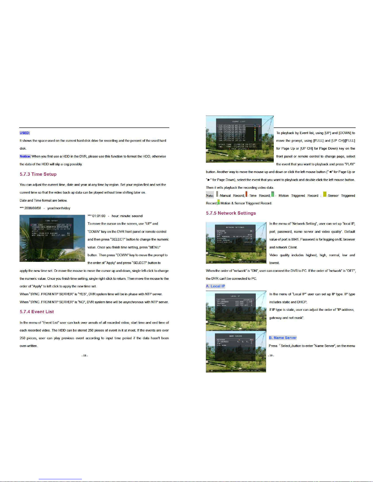
bar the order of “Network、IP Address、Port and DVR Name” can be modified. Press「 Up」and
「 Down」to move prompt. Press 「 Select」to enter into each submenu. Press「 Select」or
「REC」to modify value.
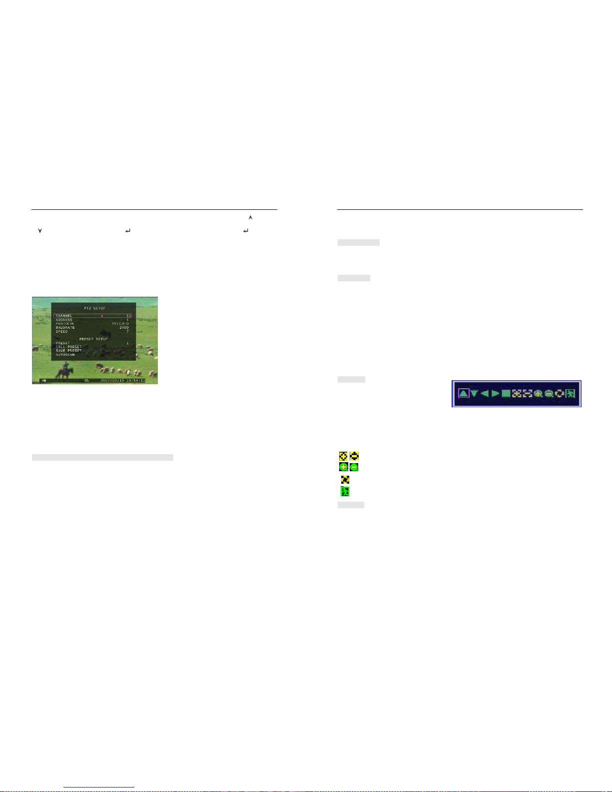
5.7.6 PTZ Setup
Press 「S
elect」 button accessing to “PTZ Setup”. Now user can select channels that he wants to set.
Then we can see the diagram that is on the left.
For example, we select the channel 1 to set up.
Dome’s address is 4. Protocol makes use of
PELCO-D. Baud rate is 2400 and Dome’s
speed is 7.
ADDRESS: Dome’s address “0-255” (PELCO-D)
and”0-31” (PELCO-P).
PROTOCOL: Including “PELCO-D”, “PELCO-P”. Setting the protocol according to the dome’s protocol.
BAUD RATE: Press “EDIT” button to select the value 1200, 2400, 4800, 9600, 19200bps.
SPEED: Having “1-10” to select.
PRESET: If protocol is PELCO-D, preset includes “1-32”. If protocol is PELCO-P, preset includes
“1-255”. When it displays 0, it suggests that the place’s preset is not using.
Button function on The Front Panel or Remote Control:
「Select」:Make sure the setting.
「Up」「Down」:Move the cursor.
「SEL」:Increase Value.
「REC」:Reduce Value.
「FULL」:Move the dome upwards.
「UP CH 」:Move the dome downwards.
「DOWN CH」: Move the dome leftwards.
「QUAD」:Move the dome rightwards.
「STOP」:Stop the dome running.
- 21 -
「REW」「Fwd」:Zoom.
「Pause」「Play」: Focus.
Mouse function:
Left Mouse: Click the icon “►” or “◄” to adjust value.
Right Mouse: Previous.
Preset setup
User must set preset at first. The address, protocol and baud rate of DVR is consistent with Dome’s.
You can make use of buttons to control dome and save the preset.
If user wants to call preset, user can modify the value of preset to come true. Press「Select」button to
finish the order of “call preset”.
User can perform auto scan when he saves the presets within cruise locus. Then he needs to press
「Select」button to finish the order of “auto scan”, the dome will run all along unless user presses
「STOP」button to stop it.
PTZ Mode:
Enter into PTZ mode and hold a left mouse
cl
ick button, there will be a piece of message
on the screen (Right FIG).
Icon function:
“▲▼►◄”: Move the dome upwards、downwards、leftwards and rightwards.
“■”: S
top the dome running.
“ 、 ”: Focus.
“ 、 ”: Zoom.
“ ”: Auto scan.
“ ”: Previous.
Attention
User can start-up automatic scout in “PTZ SETUP” menu
or PTZ mode. It doesn’t stop when user exits.
If user wants to stop scouting, press 「STOP」button in PTZ SETUP menu or PTZ mode.
During live view, user can press 「PTZ」button to enter PTZ SETUP, and then user can operate to
control the dome according to the method of above paragraphs.
Page 12
- 22 -
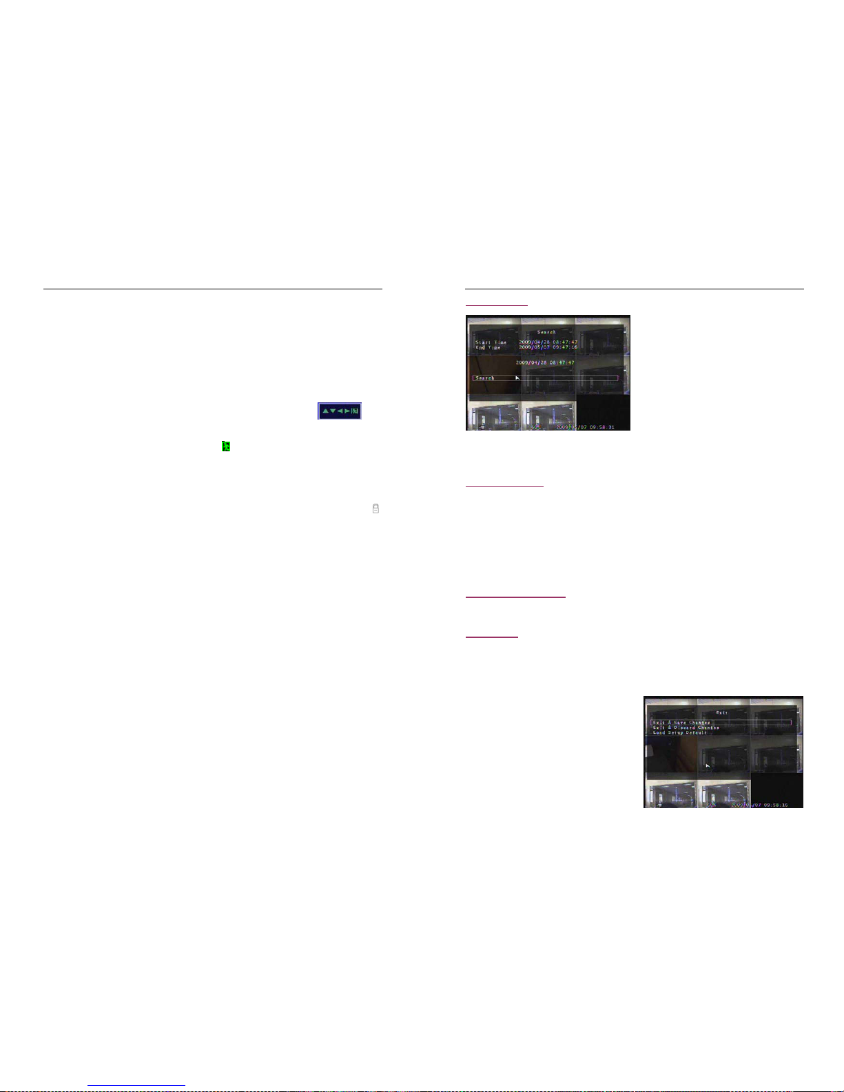
5.7.7 Screen Adjustment
Press「Select」button accessing to “ Screen Adjustment”. You can move the entire video screen up,
down, left, and right using this option.
Keypad assignment in the front panel or remote control is below:
-FULL for up, UP CH for down, DOWN CH for left, QUAD for right.
M
ouse function:
Hold a right mouse click button, there will be some icons on the screen as follows “ ”.
Hold a left mouse click button to click each icon to select.
-“▲”for up, “▼” for down, “◄” for left, “►” for right, “ ” for ESC.
5.7.8 Key lock
“Key Lock” can be set as “1~10(in minutes)、、、、Off”. It decides how much time the system will be locked
automatically if user can’t operate the system beyond the period. If “Key Lock” is working, the icon “ ”
will appear on screen, and you must input the password to continue working.
5.7.9 Border
User can make the white borderline around each channel to appear or disappear by using this option to
be “on” or “off”.
5.7.10 Auto sequence
This is for auto screen switch rotation. Value at “Off、1
~10(in seconds)”. Default at “Off”.
5.7.11 Upgrade Firmware
This menu is for firmware upgrade of DVR system through USB host (USB memory stick) connection,
y
ou can simply upgrade the system once you connect the USB memory stick that contains a firmware
file.
[CAUTION]: 1. Do not turn off the system while the system is up
grading. Otherwise, it will cause the
breakdown of the system that needs a special recovery process.
2. If you don’t install a HDD in the DVR, the system can’t be upgrade.
3. Before the system is upgrade, you must stop recording.
- 23 -
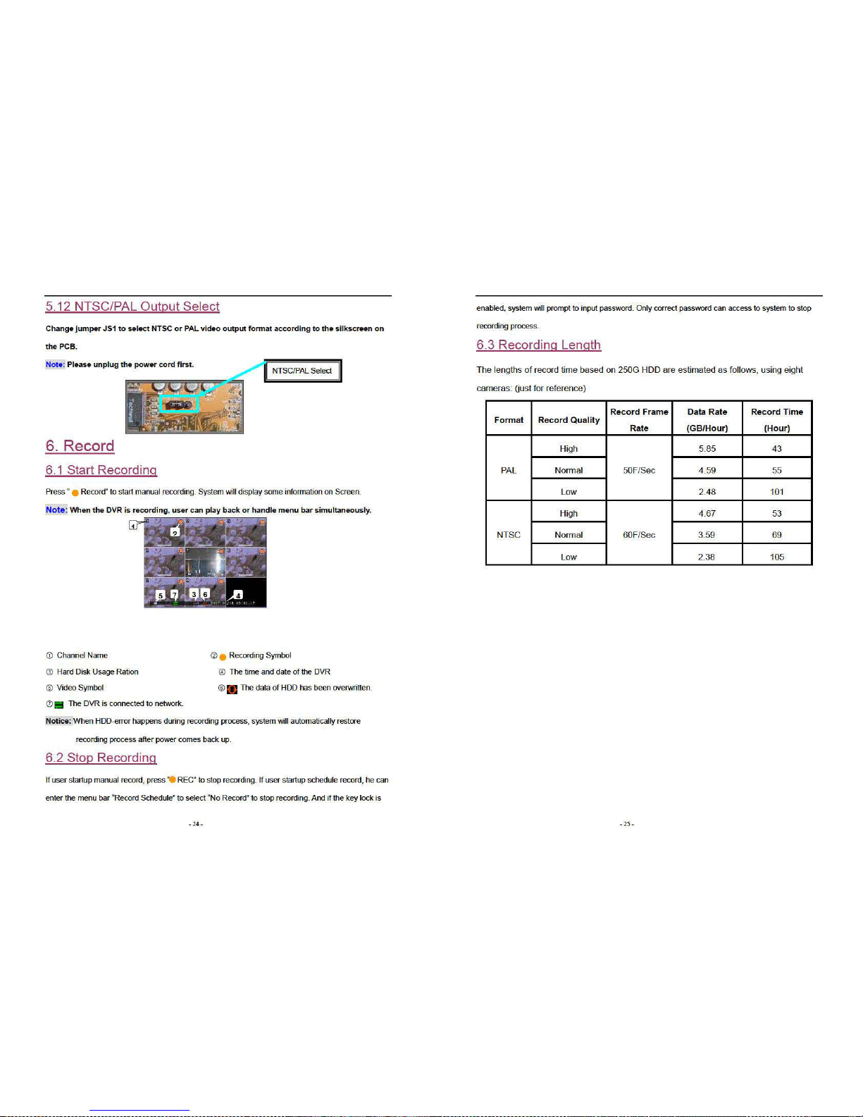
5.8 Search
Press the button「SEL」 to enter “ Time Search”, on
the menu user can look over start time and end
time of all recording. Press 「SEL」to enter option
of time to adjust the time you want to search.
Finish adjusting time, press「MENU」to confirm.
Then press 「Play」directly . Or move the prompt to
the order of “Search” , and then press 「SEL」.
If the time is within recording range, wait for a moment it will play from the time you searched. If the time
goes beyond recording range, it will display black on the screen.
5.9 Language
Press the button 「Select」to change language. As a whole it includes two types of language system
(western and east). The language is provided with user’s requirement. In western language user can
choose either Chinese、English、Italian、Polish、Spanish 、France、German、Russian、Portuguese
or Turkish for display on the screen. In east language user can choose either Chinese or Japanese for
display on the screen.
5.10 Keypad tone
Make the keypad tone “ON” or “OFF” to enable or disab
le keypad tone during operating.
5. 11 Exit
After you change setting on DVR menu, you need to con
firm the changes under EXIT menu.
When choose the order of “Exit & Save Changes”, it will come back to live view and the setting will be
saved.
When choose the order of “Exit & Discard Changes”,
it will come back to live view and the setting won’t be
saved.
When choose the order of “Load Setup Default”, all
settings will be restored factory default except time.
Page 13
Page 14
Page 15
- 28 -
icon.
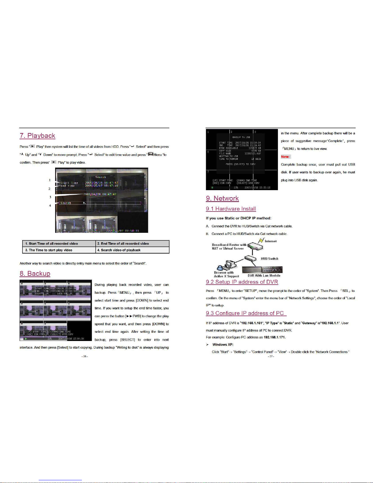
Find “Local Area Connection” and Right Click and select “Properties”.
Find “Internet Protocol [TCP/IP]” and click “Properties”. Select “Use the following IP address” and “Use
the following DNS server address”, and then input IP value.
Finally, Click “OK” to Save Change.
Note: Before connecting network make sure the order of “Network” is “ON” on the menu “Network
settings”.
9.4 Connect PC to DVR—Net Viewer
9.4.1 Install
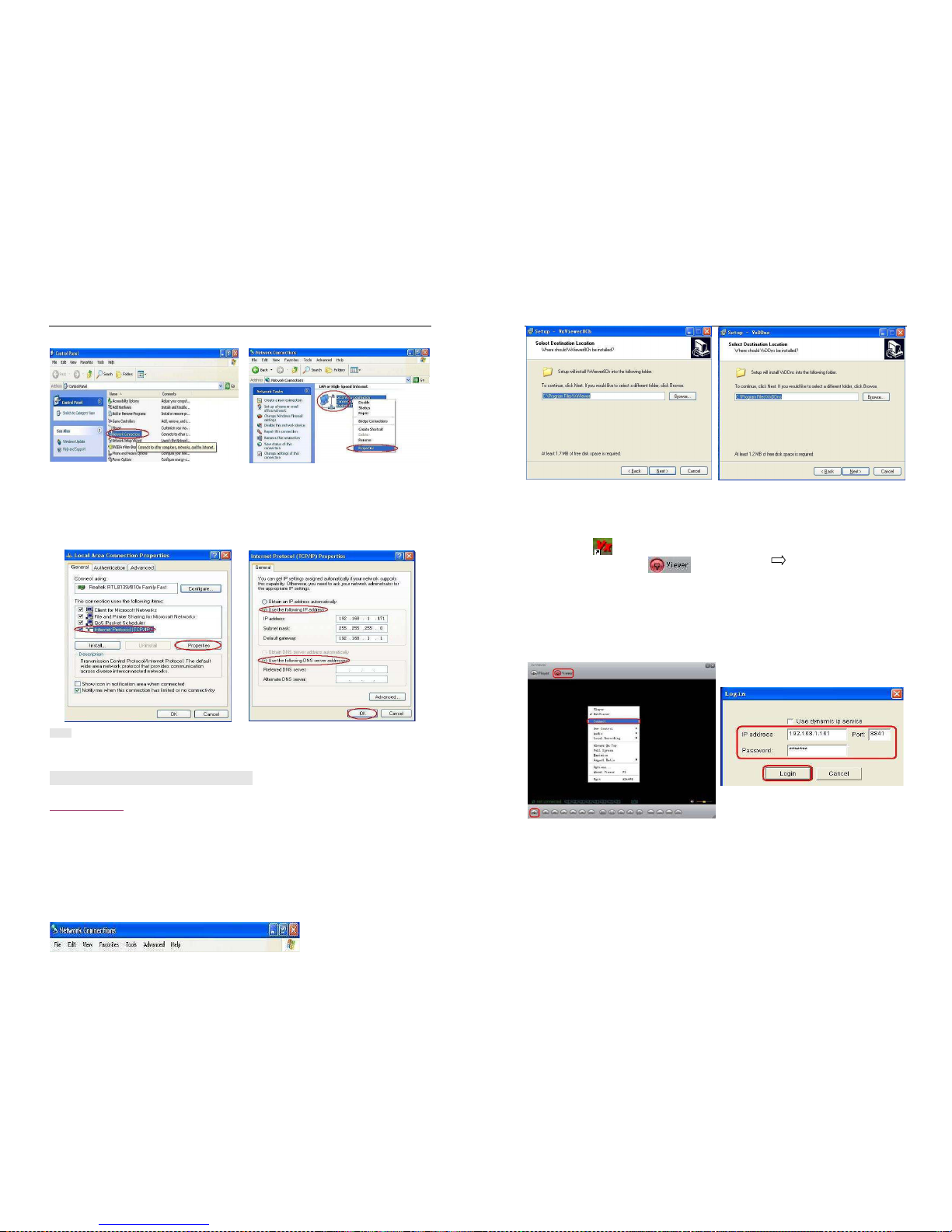
1. Put the Driver Program CD in your CD-ROM.
2. Go for installing by setup.
3. Set up the install directory.
4. Execute: 1.Start >Program> VxViewer8Ch.
2.Start>Program> VxDDns.
- 29 -
9.4.2 Program Interface
A: Run Vxviewer8Ch.
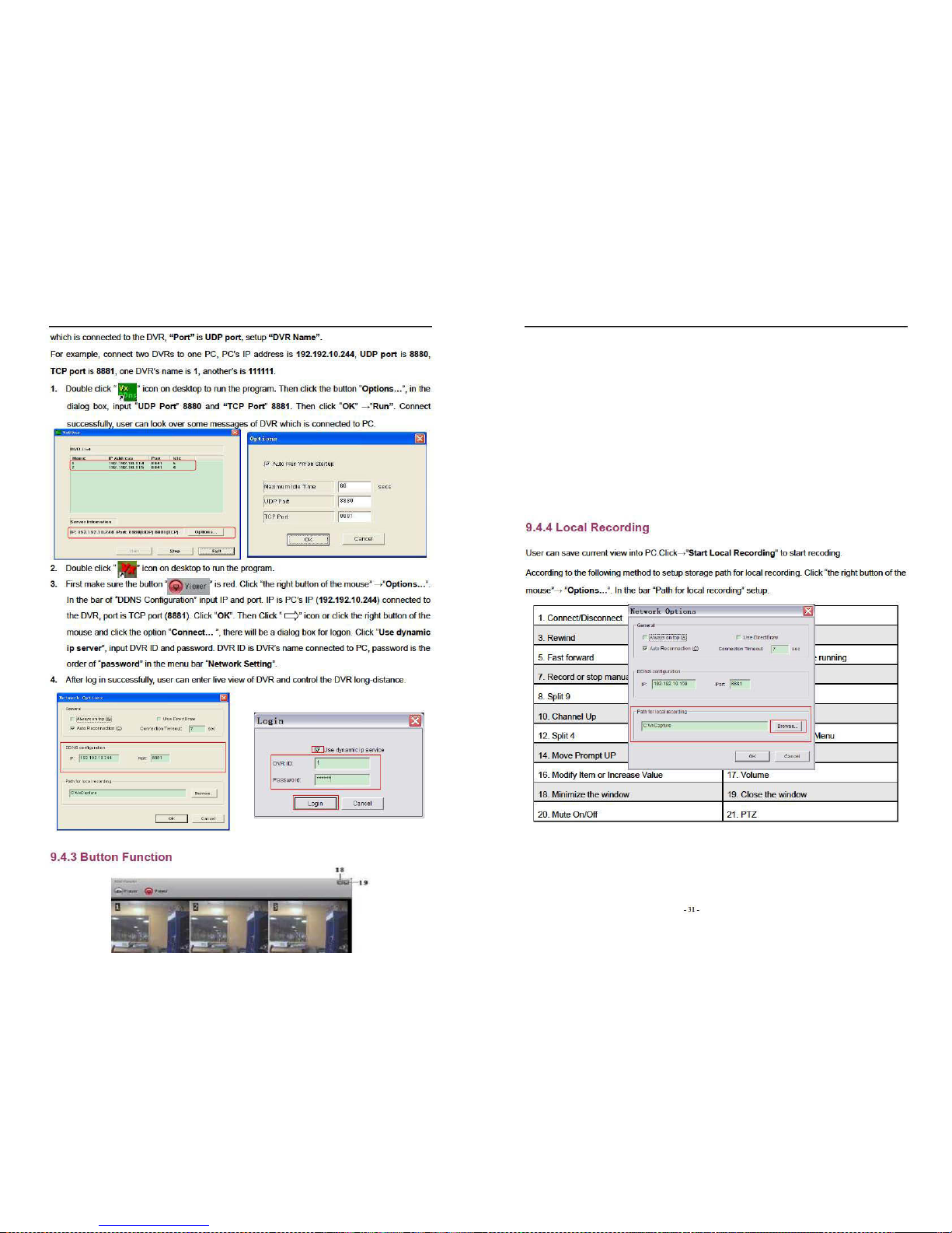
1. Double click “ ” icon on desktop to run the program.
2. First make sure the button “ ” is red. Then Click “ ” icon or click the right button of
the mouse and click the option “Connect… ”, there will be a dialog box for logon. To input IP
address, port and password according to the order of “Local IP” of DVR in the dialog box. For
example, “IP Type” is “Static”, “IP Address” is “192.168.1.161”, “Gateway” is “192.168.1.1”. Then
click the button “Logon” to enter into live view.
When browser net viewer, user can click the buttons on the interface to control DVR.
B:
Run VxDDns.
Make use of VxDDns, user can connect synchronously many DVRs to one PC.
Fir
st set up DVR, enter menu bar “Network Settings”, adjust “Network” is “ON”, select order of “Name
Server”. On the interface of “Name Server”, make sure “Network” is “ON”, “IP Address” is the PC
Page 16
Page 17
Page 18
- 34 -
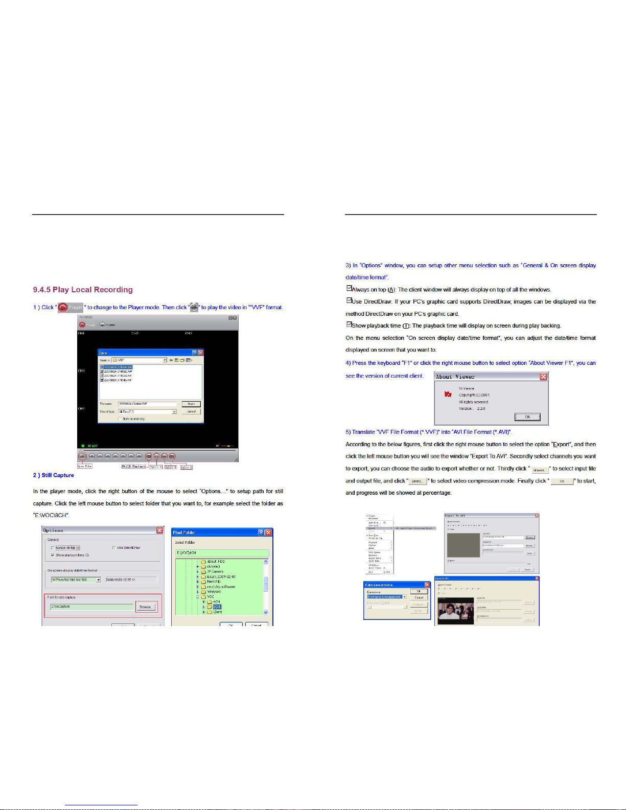
Note:1、When selecting video compression mode, user had better to test the compression that he
selects is matching with his computer whether or not. Or else the transposition AVI file will be failed
possibly.
2、1) Audio: The audio will be backup if the video data include audio.
2) □Audio: The audio won’t be backup.
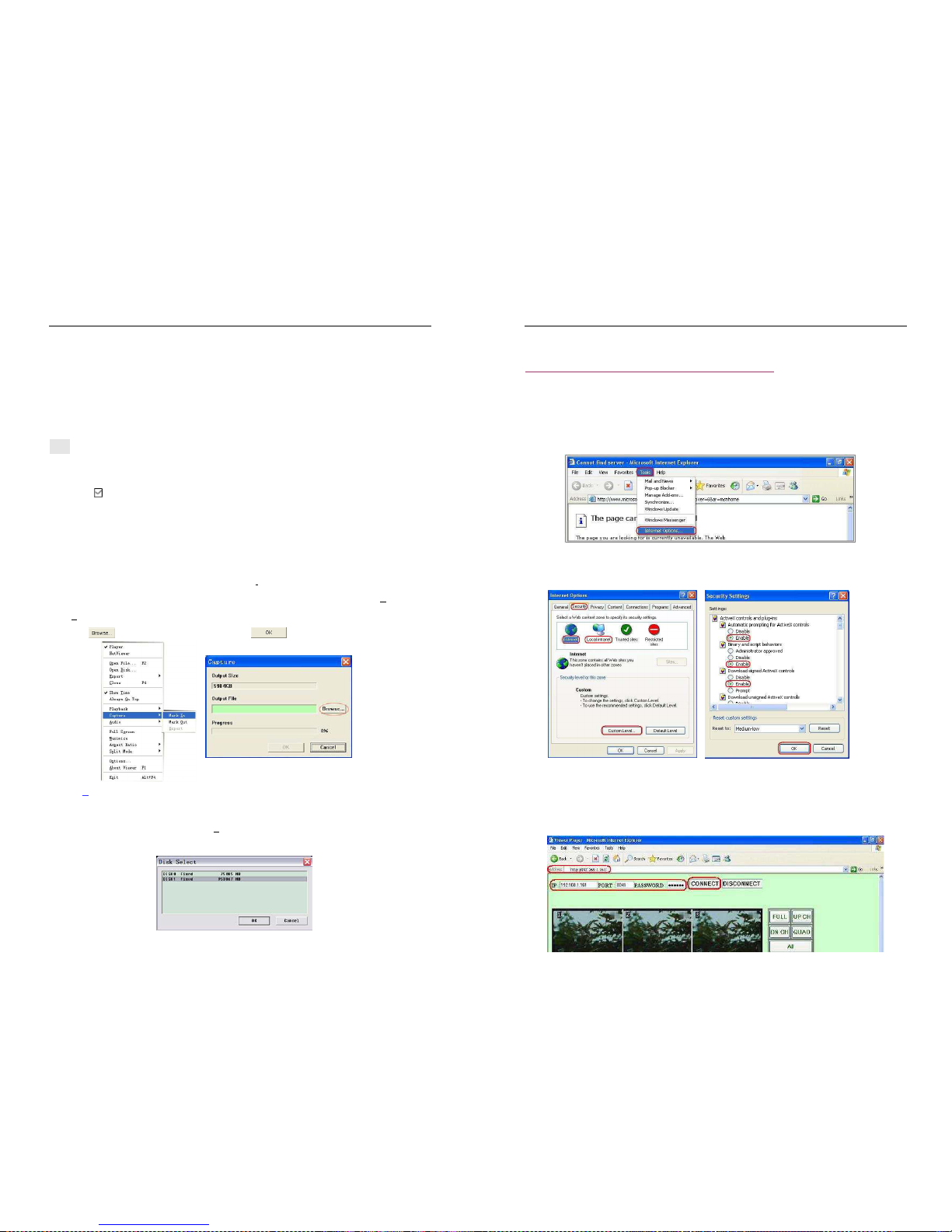
6) Capture
If you want to save moiety of VVF file format (*.VVF) on your computer rapidly, you must make sure the
playback view be in pause state. Drag playing scroll bar to select start time, click the right mouse button
to select the option “Capture”, and then left click “Mark I
n”. Drag playing scroll bar ahead to select end
time, click the right mouse button to select the option “Capture”, and then left click “Mark Out”. Last left
click “E
xport” and there will be a window “Capture” on screen. The “Output Size” is the size of output file.
Left click “ ” to setup save path. Then left click “ ”.
7) Open D
isk…
User can playback the record data in the HDD directly
through the client software. User can install the
HDD to PC directly. Click the option “Open D
isk…”, and there will be a dialog of “Disk Select”. Select
the HDD including video data to play.
- 35 -
9.5. Connect PC to DVR — IE Browser
At first please turn all the Active X option ON at IE Internet safety setup. Select menu setup to enable
the Active X option.
Network module use Active X applet to display remote image. Any web browser with Active X support
can connect to DVR.
Click “Start”→ ”Program” →”Internet Explorer” →”Tools” →”Internet Options…”.
Click “Security” → “I
nternet” → “Custom Level…”.
Click “Security” → “Local intranet” → “Custom Level…”.
Make sure all the ActiveX controls and plug-ins are in “enable” mode. Click “OK”.
Open IE browser and input IP address of DVR in address
bar. Press “Enter” to connect PC to DVR.
In the interface of “Viewer Player”, input “IP”、”PORT”、”PASSWORD” of DVR, then click ”CONNECT”
to enter live view of DVR. Click buttons on the right to control DVR directly though network.
NOTE: All the button functions on the right are the same as DVR’s.
Page 19

- 36 -
- 37 -
10. Specification
ITEM DESCRIPTION
Video Format NTSC / PAL
Camera Input Channel 8 channel Composite BNC
Video Output Channel 1 channel Composite BNC
Recording Speed
NTSC:Max 60 fps (Total);
1fps~Max. 30 frames/s (Each Channel);
PAL:Max.50 fps (Total);
1fps~Max. 25 frames/s (Each Channel)
Recording Mode
Time schedule, Motion detection, Sensor activated, Motion detection &
Sensor activated
Resolution
Display
NTSC:704×480;
PAL:704×576;
Recording
NTSC:640×240(Half D1)
PAL:640×288(Half D1)
Compression Method
Enhanced MJPEG Recording(12-20K Bytes/frame);
MPEG 4-like Network Streaming;
Hard Disk Capacity
Over 1.0TBytes SATA Interface HDD×1
Estimated Record Length
120G Hard disk @ 50 fame per second @ Normal Quality
(120*1024*1024 K byte) ÷ (50*15*60*60) = 46 Hours
Recording Time 10days with 500GB HDD@ 25 fps for continuous recording mode.
LCD Display
15’’ color LCD, 1024*768, 450:1; View angle: 120。(H)100。(V)
Sensor, Alarm
4 Input (Normal Open / Normal Close)
1 Output (Alarm) (12 Pin DIP Switch)
PTZ(RS485 interface)
YES, 2 Pin for RS485 control Pan/Tilt/Zoom
Protocol:PELCO-D、PELCO-P
Page 20
- 38 -
Audio YES 1CH RCA input, 1CH RCA output to monitor
Network IE View YES, RJ45
USB USB for media Backup and software upgrade
Power Input
100-240VAC/DC 12V,5A(Adapter supplying)
Dimension Length 312mm * Width 360mm * Height 52mm(Not including bracket)
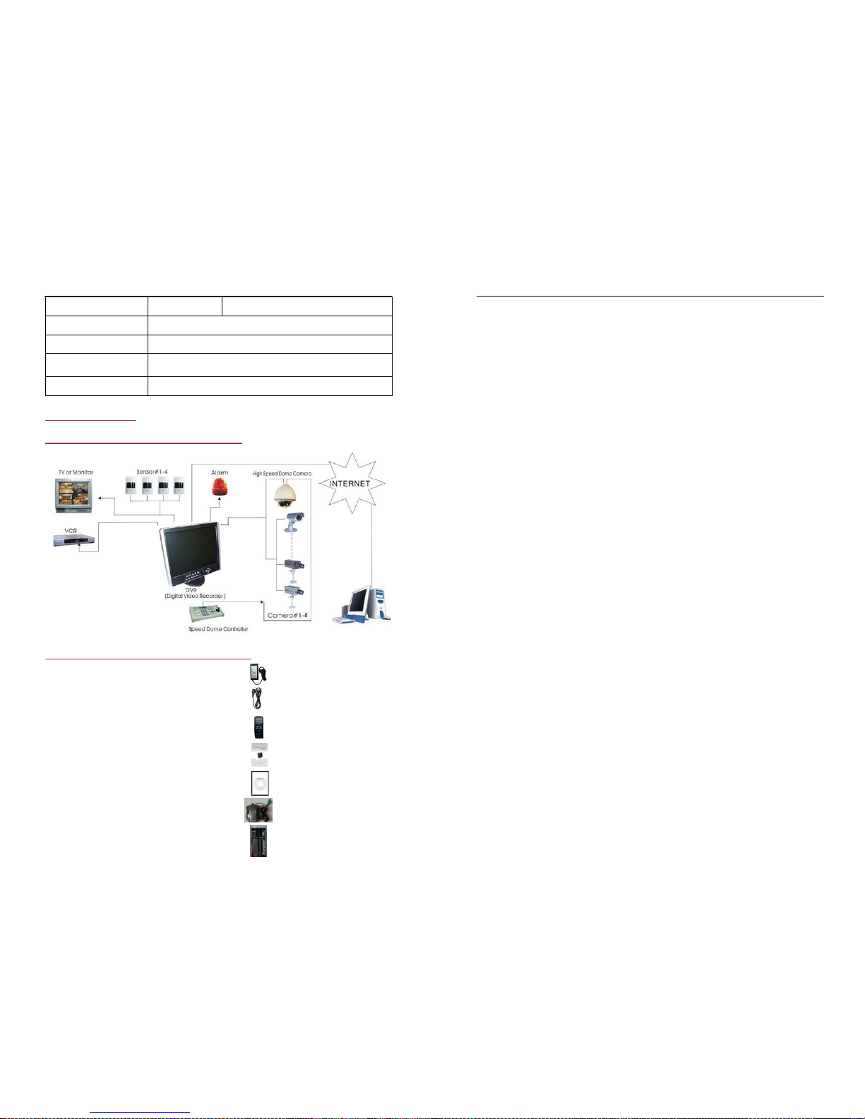
11. Appendix
11.1 System Connect Sketch Map
11.2 Fittings Come Along With DVR
1. Power Adapter 1pcs
2. P
ower Cord 1pcs
3. Remote Control (Optional) 1pcs
4. User Manual 1pcs
5. USB Drive CD 1pcs
- 39 -
6. PS/2 Mouse (Optional) 1pcs
7. Batteries of Remote Control 1pcs
 Loading...