

Page 1
ELEKTRONISCHE REGELUNGEN GMBH
Technical Manual
Dual-Setpoint and PI-Controller for
Temperature-, Pressure or Humidity
6)4N $
Software Version from 040603
Nr. 5311032-03/07 E
l Usable as: Temperature-, Humidity-,
Pressure- or Cold Storage Controller
with relay outputs
l Operation Modes: Double Single
Setpoint, Dual Setpoint, Proportional-/
PI-Controller, Step Controller,
Setpoint shift by 2nd sensor,
Cold Storage Control with Cyclic
Defrost
l Output 0-10VDC delivers control
deviation or an actual value image
Please note Safety
Instructions !
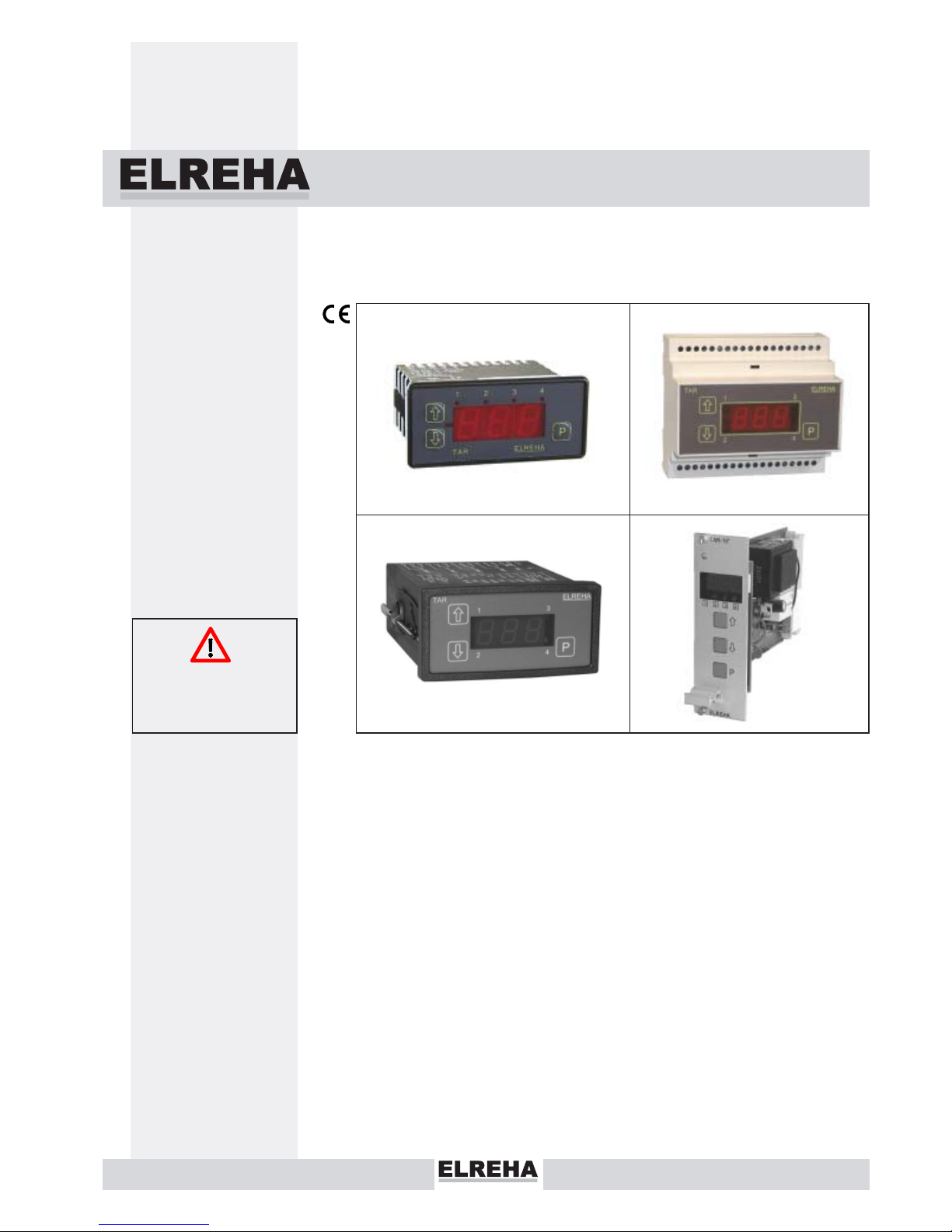
TAR 1260
TAR 3260
TAR 5260
TAR 19260
l Limit value alarm, Alarm relay
l Inputs for PTC/Pt1000 and 4...20 mA
for any 2-wire-transmitters
l 2. setpoint by Digital Input
l Minimum Stop-time
l RS-485-Interface
l 4 different housings
Page 2
Page 2
Technical Manual Temperature-, Humidity-, Pressure-Controller TAR x260
Technical Data
Operating Voltage .............. see type overview
Power Consumption ........... approx. 3,5 VA
Output relays....................... 3 x potential free
Relay rating ........................ 8A cos phi=1, 3A ind. / 250V AC
Operating Temp. ................ -10...+55°C / 14...131°F
Storage Temp..................... -30...+70°C / -22...158°F
Air humidity ......................... max. 85% r.H., not condensing
Signal inputs....................... 2x TF 201 (PTC) or TF 501 (Pt1000),
1x 4...20 mA, 100 ohms shunt
Transmitter supply .............. appr. 12VDC unreg., max. 35 mA
Display ................................ LED, character height 13mm
19"-module : char. height 10mm
Resolution........................... 0,1 / °C, 0,2 / °F
Control-/Display range ....... -100...+300 (°C, bar, °F up to +572)
Data storage parameters ... typ. 10 years
Relay indicator.................... LED 2 mm, red
Digital Input (Optocpl.) ....... 230V, 3mA (1260: external switch)
Analogue output .................. 0-10 V DC, max. 3 mA
Resolution Analogue Outp. . 8 bit within the set limit values
Data interface ..................... RS-485 (
E-Link
)
Electrical connection .......... Screw terminals 2,5mm
19"-module : connector "F"
Housing, Protection
TAR 1260 ................ 77 x 35 mm, IP 54 from front
TAR (2)3260 ............ for 35mm DIN-rail, IP 30
TAR (2)5260 ............ 96 x 48 mm, IP 54 from front
TAR (2)19260 .......... 19"module, 8 TE
Further information you will find in the parameter listing
Type Overview
TAR 1260 ........... Panel mounting, 12-24V AC/DC
TAR 3260 ........... for 35mm DIN-rail, 230V~, 50-60 Hz
TAR 5260 ........... Panel mounting, 230V~, 50-60 Hz
TAR 19260 ......... 19"-Module, 8TE, 230V~, 50-60 Hz
TAR 23260 ......... for 35mm DIN-rail, 115V~, 60 Hz
TAR 25260 ......... Panel mounting, 115V~, 60 Hz
TAR 29260 ......... 19"-Module, 8TE, 115V~, 60 Hz
Accessories (please order separately)
- Temperature sensor TF 201 (max. 80°C)
or
PT1000 (max. 300°C)
- Two-wire pressure transmitter, Type DG... or similar with
4-20 mA signal output
- Humidity transmitter FF 2520 with 4...20mA output
- For type TAR 1260: Matching transformer, please contact us.
- For type TAR 19260: Subrack or Panel housing
Contents
page
Safety Instructions ..........................................................2
Operating / Operating Elements / Failure Displays..........3
Access protection .............................................................. 3
Parameter listing ............................................................... 4-5
Functional Description
Value sources, Operating modes
Alarm, Switching modes, Digital Input, Analogue output
Networking.........................................................................9
Dimensions/ Wiring ........................................................... 11
Run-Up Examples ............................................................. 15
Please read before Start-up
• Limit of Application: This product is not designed nor
manufactured for use in equipment or systems that are
intended to be used under such circumstances that may
affect human life.
For applications requiring extremely high reliability, please
contact the manufacturer first
• Electrical installation and putting into service must be
done from authorized personnel.
• Please note the local safety instructions !
• Before installation: Check the limits of the controller and
your application. Before starting up we recommend you to
read the following instructions for use, since only by doing
so you can avoid damage or malfunction and you will
benefit all the advantages offered by this product.
• During installation and wiring never work when the
electricity is not cut-off !
• If the units should be networked, never connect the
secondary coil of 12/24V transformers to PE !
• To control servo drives/actuators, a TAR 1260 must be
supplied by a separate transformer
• Mounting the controller close to power relays is
unfavourable in case of the electro-magnetic interference.
• Before applying voltage to the controller:
Make sure that all wiring has been made in accordance
with the wiring diagram in this manual.
Check, if the supply voltage corresponds to the value
printed on the type label.
• Connect the ‘PE’ terminal carefully to ground because
otherwise the operation of the internal noise filter will be
disabled.
• Respect the environmental limits for temperature and
humidity. Outside these limits malfunctions may occur.
• Never operate unit without housing.
• Observe the maximum admitted current rate for the
relays (see technical data). Compare with the peak startup current of the controlled devices (valve, fan,
compressor, heater..)
• Sensor cables may be up to some hundred meters in
length. Use shielded sensor cable only. Don’t install them
in parallel with high-current cables to prevent inductive
interference. A cross section of min. 0,5mm² is sufficient.
• Shielding has to be connected to PE at the end near the
controller
• All used temperature sensors must be identical. Never
use PTC (TF 201) and PT1000 (TF 501) mixed. This will
not work.
• TF-type sensors are moisture-proof but they are not
designed for being immersed in water for a long period of
time (not pressure-proof). In such a case, always use dipfittings.
• Be care that the wiring of interface lines meets the
requirements
CONNECTION & SAFETY INFORMATIONS
Page 3
Technical Manual Temperature-, Humidity-, Pressure-Controller TAR x260 Page 3
Operating
Operating Elements
Parameters (setpoints, times, etc.)
All selectable parameters hold a parameter number (e.g. P03), you
will find a listing on the next page.
Calling up and editing
Press key 'P'............. parameter number appears
Use 'ñ/ò' .................select desired parameter
Press "P" again ........ parameter value appears
Use keys 'ñ/ò' .........adjust parameter value
Press 'P' again .........value is stored, back to parameter no.
Auto scrolling
Hold 'ñ/ò'-keys to scroll values automatically.
Manual Defrost
In cold storage controller mode (P14=4) and while the actual control
value is displayed, a defrost event can be initiated by holding the 'ñ'-
key for more than 2,5 seconds.
The defrost event can be terminated holding the 'ò'-key for more
than 2,5 seconds.
Detecting controller type without a type label
1. Switch off supply voltage
2. Push and hold key 'P'
3. Switch on power again.
Now the display shows one after another :
"SOF" (Software), "260" (for x260), year, month and day of
manufacturing.
flashing:
Data transmission
flashin
g
:
2nd setpoint active
Programmin
g
key
minusindicator
Stage 2 ON/OFF
decrease
values
TAR
2
Stage 1 ON/OFF
increase
values
1
Alarm
ELREHA
4
P
If ON in op-mode 3:
Setpoint just shifted
If ON in op-mode 4:
Defrost runs
3
All TAR-versions are marked in the same way
Unlock Keys
To prevent un-authorized persons from editing parameter values, there
is a locking function which allows only the most important parameters
to be changed at any time. All other parameters must be unlocked
beforehand. This means that at parameter P43 a certain value is to be
set (see parameter listing) :
Press key "P"............. parameter number appears
Use "ñ/ò" ................. select code parameter (P43)
Press "P" again ......... parameter value appears
Use "ñ" ..................... set value to --88--
Press "P" again ......... value is stored, back to parameter no.
If no key is hit for about 4 minutes, the access code is cancelled and the
editing function is locked automatically.
Error Display / Error Behaviour
Display shows "oFF":
The controller unit is disabled via
digital input OK1 or via network
interface (DDC).
If the controller has been de-activated via interface before, it can be
waked up manually by holding the 'ò'-key for more than 3 seconds.
Display flashes, without minus sign:
Using temperature sensors=
O
ne of the two sensors is
broken or wrong type
Current input = > 25mA
Display flashes, with minus sign:
Using temperature sensors =
O
ne of the two sensors has short-circuit or wrong type
Current input = < 2mA
All control relays (K1 + K2) switch off immediately. Additionally to
the flashing display, an alarm delay runs (P31), after this timer is
run run down, the alarm relay (K4) will be activated.
If sensor errors occur, P31 is always < 1min.
Page 4
Page 4
Technical Manual Temperature-, Humidity-, Pressure-Controller TAR x260
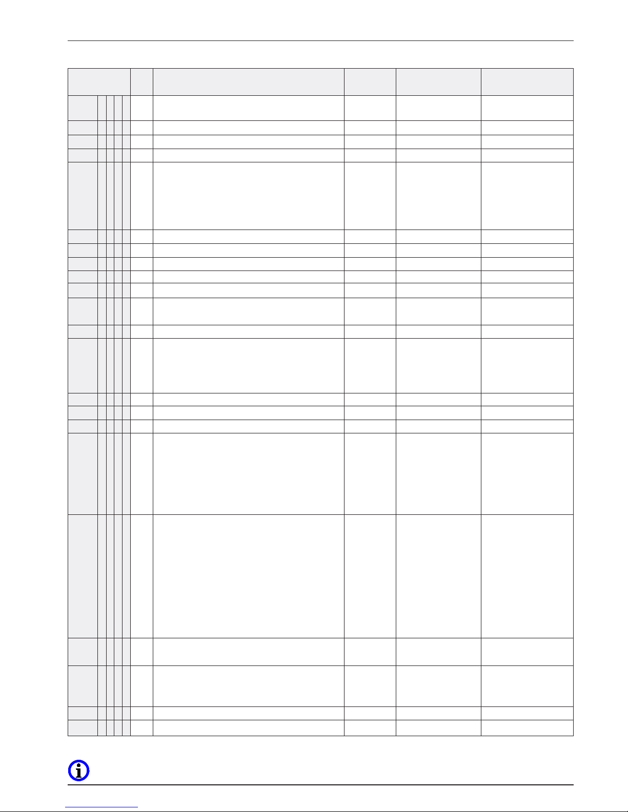
Param.-No
Code
Description Default val. Limits Your value
P01 x x x x - Actual value of sensor/transmitter 1 - - -
P02 xxx- Actual value of sensor 2 - - -
P03 x x x x - Control setpoint 1 (
Absolute value
) 0 Within the limits
set by P10/P11
P04 x x x x - Control setpoint 2 0 Within the limits
(
Absolute/Relative, depending on P05.
set by P10/P11
Relative value can be also set to negative
)
P05 x x 88 Mode of setpoint 2 1 1= Absolute value
2= Relative to P03
(
Switching distance
)
P06 x x x x 88 Setpoint-Offset (for day/night-switch) 0 -100...+100°C
Value the setpoints will be shifted after control
input is activated (P34=1).
P07 x x x x 88 Switching mode of relay 1 1 1 = Refr.
(=de-humid.)
2 = DF, 3 = HT
= moisten
, 4 = cycling
P08 x x x x 88 Switching mode of relay 2 1 1 = Refr.
(=de-humid.)
2 = DF (not TAR 1x),
3 = HT, 4 = cycling
P09 x x x x 88 Switching mode alarm relay 1 1 = de-activated if P01
is too high/low, sensor error
2 = activated if P01
is too high/low, sensor error
3 = activated if P02
is too high/low, sensor error
4 = activated P02
is too high/low, sensor error
P10 x x x x 88 Highest with P03 resp. P04adjustable setpoint +50°C -100...+300°C
P11 x x x x 88 Lowest with P03 resp. P04 adjustable setpoint -50°C -100...P10°C
P12 x x x x 88 Hysteresis of Setpoint 1 (relay 1) 2 0,2...20
P13 x x x x 88 Hysteresis of Setpoint 2 (relay 2) 2 0,2...20
P14 xxxx 70 Operation Mode 2 1 = 2x temperature sensor
2 = 1x temperature sensor
3 = 1x temperature sens. +
1x sensor for setpoint shift
4 =like 1, with cyclic defrost
5 = 1x 4/20mA signal +
1x temperature sensor
P15 x x x x 88 Minimum idle time (relays 1 & 2) 0 0...59 min
P16 x x x x 88 Proportional range rel. 1 (
Heating resp. moisten
) 2.0 0...12
P17 x x x x 88 Proportional range rel. 2 (
refrig. resp. de-humid.
) 2.0 0...12
P18 x -- Sum of all current setpoint shifts - Display only ! -
(Setpoint -Offset + Shift)
P19 x 88 Limit value of setpoint shift 0 -100...+300
P20 x 88 Range of shift 0K -100...+100K
P21 x 88 Size of shift 0K -100...+100K
P20 x 88 Defrost cycle (h) 1 1...100 h
P21 x 88 Defrost duration (min) 1 1...100 min
P22 x x x x -- Remaining time alarm delay - Display only ! -
Parameter Listing
P14=1
P14=2
P14=3
P14=4
If P14=4 only
If P14=3 only
Page 5
Technical Manual Temperature-, Humidity-, Pressure-Controller TAR x260 Page 5
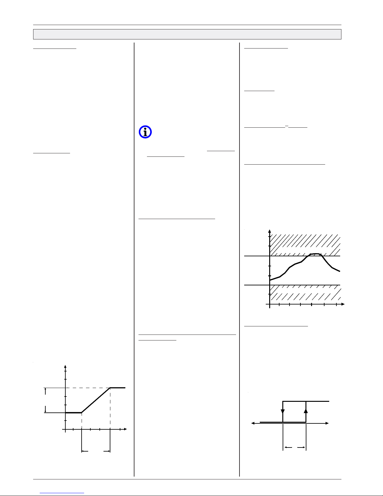
Parameter Listing (contin.)
x = Functions available in this mode, without "X" = Parameter invisible.
Parameter-
Code
Description Default val. Limits Your value
number
P23 xxxx -- Remaining idle time relay 1 - Display only ! -
P24 xxxx -- Remaining idle time relay 2 - Display only !
P25 xxxx -- Remaining time Digital Input delay (OK 1) - Display only !
P26 xxxx 70 Sensor type 1 1 = TF 201 (°C)
(sensor types 1-4 only valid for OP-modes 1,3,4, 5,
2 = TF 201 (°F)
with op-mode P14=2 all types usable,
3 = Pt1000 (°C).
with op-mode P14=5 this selection affects to sensor
4 = Pt1000 (°F)
input 2 only, sensor input 1 then is 4...20 mA)
5 = 4...20 mA
P27 xxxx 88 Sensor / Transmitter 1 (P01) correction 0 -10,0...+10,0
P28 x x x 88 Sensor 2 (P02) correction or cut-off 0 oFF, -10,0...+10,0
P29 x 88 Displayed value at 20 mA input current 100 -1.0...+100.0
P30 x 88 Displayed value at 4 mA input current 0 -1.0...+100.0
P31 xxxx88 Alarm delay 5 1...99 min
P32 xxxx88 Upper alarm limit
(Relative, related to the active,
- 0...300
potentially shifted setpoint 1)
P33 xxxx88 Lower alarm limit
(Absolute value)
-100 -100...+300
P34 xxxx88 Digital Input 1 (OK 1) 0 0 = input disabled
1 = Night setpoint
2 = External Alarm
3 = Unit OFF
P35 xxxx88 Delay time for Digital Input OK 1 2 0...99 min
P36 xxxx88 Analog output: 10V DC at this value of P01 0 -100...+300
P37 xxxx88 Analog output: 0V DC at this value of P01 0 -100...P36
P38 xxxx88 Analog output: Slow-down time (I-part) 0 0 = disabled
1 = approx. 0,25 min
2 = approx. 0,5 min
3 = approx. 1 min
4 = approx. 2 min
5 = approx. 4 min
P39 xxxx88 Analog output: Mode 0 0 = output disabled
1 = Proportional
2 = Antiproportional
3 = Proportional,
relative to the active
control setpoint
4 = Antiproportional,
relative to the active
control setpoint
P40 xxxx88 Factor of period duration 1 1...10
(Period duration = 16 sec. * factor)
P41 xxxx88 Data transmission speed (Baudrate) 4 1 = 1200, 2 = 2400,
3 = 4800, 4 = 9600
5 = 19200
P42 xxxx88 Adress of unit in a network 78 0...78 -
P43 xxxx- Access code 0 0...99
P14=1
P14=2
P14=3
P14=4
Page 6
Page 6
Technical Manual Temperature-, Humidity-, Pressure-Controller TAR x260
Functional Description
Sensor connection
The controller operates either with temperature
sensors of the types TF201 (PTCs) and TF 501
(PT1000) or with a 4...20 mA signal. The input
will be selected by parameter P26.
The selection of inputs and sensors depends
on your requests:
Temperature Controller
:
For temperatures < 80°C use sensors
TF 201 or TF501.
For temperatures > 80 up to 300°C you
must select an appropriate Pt1000 sensor.
Pressure controller
:
4...20mA from pressure transmitter
Humidity controller
:
4...20mA from humidity transmitter
Operation modes
The controller can be configured for different
operating modes (with parameter P14):
P14 = 1
: 2 control sensors
Sensor 1 effects to setpoint 1, sensor 2
effects to setpoint 2. So you realize 2
independent single stage temperature
controllers in one unit. In this mode the
4...20mA input is de-activated.
P14 = 2
: 1 control sensor or transmitter
(dual stage control)
Sensor Input 1 or the 4...20 mA Signal
Input effects to both setpoints (P03 / P04),
Sensor Input 2 is de-activated. P03 is an
absolute value, P04 can be also relative
(adjustable by P05).
P05 = 1: Setpoint 2 (P04) is an absolute
value (used for dual stage control
with individual setpoints)
P05 = 2: Setpoint 2 (P04) is a relative value
(used for dual stage control with
neutral zone, that means that P04
will be shifted the same amount if
P03 is shifted)
P14=3
: 1 control sensor + 1 sensor for
setpoint shift
Sensor 1 effects to setpoint 1 (P03), sensor
2 may shift setpoint 1. The 4...20 mA input is
de-activated. With this, you realize e.g. an
outdoor temperature guided control.
P19 is the limit from which a rise or lowering
(shift) becomes possible, P20 is the range
of the shift, P21 the amount of the shift.
Example:
- Control Setpoint 1 P03 = 10°C
- Limit value P19 = 20°C,
that means increasing starts with 20° at
sensor input 2, below that value there's no
shift.
- range of shift
P20 = 5K
,
that means shift range is 25K in total, above
25°C at sensor 2 maximum setpoint shift.
- Size of shift
P21 = 8K
,
from 25°C the control setpoint is P03 + 8K, in
this example = 18°C.
P18 shows the current shift amount. This
value is a sum of the day/hight shift and
the setpoint shift.
P14 = 4
: 2 control sensors, cyclic defrost
function is active.
Sensor 1 effects to setpoint 1, sensor 2
effects to setpoint 2. With this configuration
you realize two independent singlestage
controllers in one unit like above, but
parameters 20/21 get a different function.
Cooling via setpoint 1 (i.e. the output
effected by setpoint 1) is disabled in specific
time intervals to enable air flow defrost.
The 4...20 mA input is deactivated.
Actual value display / status display
With temperature sensors:
Temperatures can be displayed in °C or °F
selected by parameter P26 (= sensor type
switch). The resolution is 0.1°C (or 0,2°F).
While operating with temperature sensors,
P01 shows the actual value of sensor 1.
You also come back to this display at P01,
if another parameter is selected and no key
is pressed for about 4 minutes.
In operation modes 1, 3, 4 and 5 P02 shows
the actual temperature value of sensor 2.
With 4...20 mA transmitters
:
In op-modes (P14) 2 and 5 the “4...20 mA”input is activated and can be read at P01.
The standard current signal can be delivered
by an 4...20 mA source or appropriate
transmitter.
Adapting of humidity and pressure transmitters,
display correction
A transmitter delivers the measured value as a
4...20 mA signal. With parameter P30/P29 the
measuring scale will be preset.
Example 1: Humidity transmitter,
Range 0...100% r.H.
P29 = 100, P30 =0
Example 2: Pressure transmitter,
Range –0,5 ... +9.0 bar
P29 = 9,0 and P30 = -0,5
With P27 the display of actual value P01 can be
corrected, with P28 a correction of the value
displayed by P02 is possible.
setpoint
amount of shift
P21 (8°)
shifted
setpoint
(18°)
setpoint
P03 (10°)
setpoint course
limit
P19 (20°)
range of shift
P20 (5K)
range
limit
(25°C)
P02
Switching hysteresis
For the setpoints P03 / P04 you can fix a
switching hysteresis with parameters P12 and
P13. The position of the hysteresis (above/
below the setpoint) depends on the selected
relay switching mode (P07 resp. P08).
Setpoint limits
To prevent the setpoints being set to an invalid
value (e.g. not below 0°C), the range of P03 /
P04 can be restricted by parameters P10 and
P11.
Day / night shift - 2nd Setpoint
E. g. to save energy it is possible to work with
other setpoints at any time. By parameter P06
an offset value can be set on which all setpoints
will be shifted if Digital Input OK 1 is activated.
Temperature- resp. Limit Value Alarm
If the value measured with sensor 1 or the
delivered 4...20 mA signal leaves the range
preset by parameters P32 and P33, then an
alarm relay and a buzzer will be activated after
a delay timer (P31) is run down. P22 shows the
remaining time of the alarm delay timer.
P33 (lower limit) is an absolute value and P32
is always a relative value coupled to the current
setpoint (P03 + eventually shift).
Relay switching characteristic
The switching characteristic of relays K1 and
K2 are defined by parameters P07 and P08.
The following options can be selected:
1= Refrigeration (Standard)
Used for standard applications (e.g.
temperatures above 0°C).
The load would be switched by the NOcontact.
alarm after P31 is run down
alarm after P31 is run down
Lower limit
P33
(absolute)
Upper limit
P32
(relative)
temperatur flow
cold
sta
g
e ON
sta
g
e OFF
warm
setpoint
hysteresis
Page 7
Technical Manual Temperature-, Humidity-, Pressure-Controller TAR x260 Page 7
cold
warm
setpoint
hysteresis
stage OFF
sta
g
e ON
cold warm
hysteresis
stage OFF
setpoint
stage ON
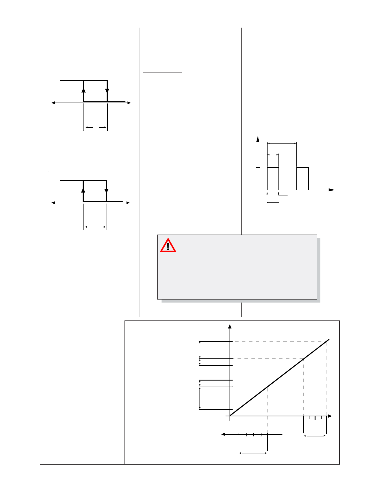
2 = Freezing (DF)
Used for temperature applications below
0°C. The load would be switched by the
NC-contact, this enables that the load will
be switched on permenantly in case of
mains loss or controller defect.
Note: not usable for relay 2 at type 1260.
3 = HT (Heating)
Usable for heating applications. Load
would be switched off in case of mains
fail or controller defect.
Use NO-Contact.
4 = Cycling
Quasi-Proportional Control with cycling
relay. Usable for heaters or certain valves.
Here a range will be defined within the relay
will cycle. The relay's ON/OFF ratio
(cycle ratio) depends on control deviation.
The period duration will be set by P40.
With P40=1 the period duration is
16 seconds, with P49=2 the duration is
32 seconds, and so on.
P16 defines the Xp-range where relay 1
cycles within.
The upper limit of this range is:
P03 (setp.1) - P12 (hyst.1).
The lower limit is built of:
P03 (setp.1) - P12 (hyst.1) - P16
If the signal reaches the hysteresis
range P12, relay 1 remains OFF
permanently, below the lower limit
relay 1 remains permanently ON
(e.g. for heating, humidifying).
P17 defines the Xp-range where
relay 2 cycles within.
The lower limit of this range is:
P04 (setp.2) + P13 (hyst.2).
The upper limit is built of:
P04 (setp.2) + P13 (hyst.2) + P17
Above the upper limit, relay 2
remains permanently ON (e.g. for
refrigeration, de-hu midifying),
below the lower limit relay 2
remains OFF.
Alarm relay characteristic
Parameter P09 defines if the alarm relay is
affected from the actual value P01 or P02 and
whether the alarm relay is activated (active) or
de-activated (passive) if an alarm occurs.
Minimium idle time
If a relay has been switched OFF, it can be
activated first after timer P15 is run down. If the
switching characteristic is set to 'cycling' this
function is de-activated.
Parameters P23 and P24 show the remaining
time until the relays will switch ON again.
Example for a cycling heater:
Switching char. ..... P07 = 4
Setpoint 1 ............. P03 = 8°C
Hyst. setpoint 1 .... P12 = 1K
P-range relay 1..... P16 = 4K
8°C = relay OFF permanently
7°C = relay OFF permanently
6°C = relay cycles, 25% ON,
75% OFF
5°C = relay cycles, 50% ON,
50% OFF
4°C = relay cycles, 75% ON,
25% OFF
3°C = relay ON permanently
Defrost Function
In operation mode 4 (P14=4) a simple defrost
function can be used. This function suppresses (in adjustable intervals) the switch-on of
relay 1 to enable an air circulation defrost.
The parameters P20 and P21 have another
significance in this mode. P20 defines the
defrost cycle, P21 the defrost duration.
After power-on of the unit the defrost cycle time
(P20) runs down first, before a defrost can
start.
To prevent a temperature alarm while a defrost
event, P31 must be lengthened eventually.
A defrost can be started and stopped manually
while the actual value is being displayed, a
running defrost event is indicated by an LED
(see 'operating').
relay 1
durably ON
7
5
%
O
N
5
0
%
O
N
2
5
%
O
N
relay cycles
relay 1
durably OFF
P-range rel.2
P17
hysteresis P13
setpoint P04 (10°)
setpoint P03 (8°)
hysteresis P12
P-ran
g
e rel.1
P16
relay cycles
relay 2
Durably OFF
2
5
%
O
N
5
0
%
O
N
7
5
%
O
N
relay 2
durably ON
Defrost Cycle
Defrost starts
Defrost ends
OFF
ON
DefrostDuration
Important !! -->
Please note the decreased lifetime of the relay contacts in
cycling operation. Please care for a suitable relief.
Cycle 16 sec.: load current 0,8A res. --> 2 years
load current 1,2A res. --> 1 year
load current 1,9A res. --> 0,5 years
(Theoretical values according to the relays data sheet)
Page 8
Page 8
Technical Manual Temperature-, Humidity-, Pressure-Controller TAR x260
Digital Input
With the Digital (optocoupler) Input OK 1, normally connected to
mains voltage, a function (preset by P34) can be activated if mains
will be disconnected from this input.
The type TAR 1260 has no optocoupler input, the
function will be activated by opening an external,
isolated contact connected to terminals 18/19.
Never connect mains voltage to this terminals !
P34 = 0 Digital Input is de-activated
P34 = 1 No voltage (1260: ext. contact open) at Digital Input 1
switches to the 2
nd
/night-setpoint. Setpoints will be
increased / decreased by the value of P06.
P34 = 2 No voltage (1260: contact open) at Digital Input 1 starts
an external alarm. After P31 is run down, the internal
buzzer and the alarm relay will be activated.
P34 = 3 If ther is no voltage (1260: contact open) at Digital Input
OK 1 all control functions will be disabled, the display
shows 'oFF'. The unit can only be reactivated by
connecting the input to mains again (1260: external
contact closed).
An adjustable delay (P35) is effectual before one of the functions
above will be started.
Networking of TAR-controllers
All TAR controllers can be networked via their builtin RS-485-interface. This network can be controlled
by a host unit.
Normally this host is a PC with a qualified software
which allows remote control of units and recording
of all parameters.
Because all units are connected parallel on the
data cable, every unit has its own network address
(P42) to ensure a specific communication.
The communication speed is fixed by P41, the
default value is 9600 Baud.
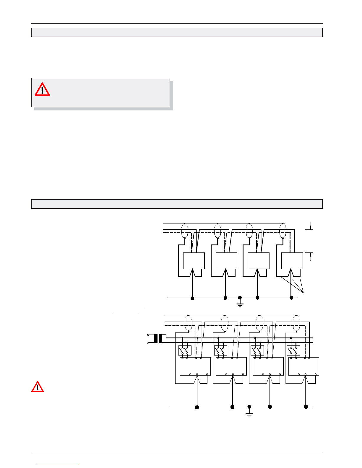
If networked controllers (1xxx types only) are
supplied by one transformer only and the single
positions must be switched off, use double-pole
switches only.
If not, the unit will be supplied partially over the
shielding of the data connection and continues
operation, depending on the secondary voltage of
the transformer.
Please note: If a unit is not supplied, the PCsoftware notifies a unit breakdown !
A better way is not to switch-off the supply voltage
but to disable the unit by Digital Input.
Important: Never connect the
secondary coil of the transformer to PE!
Attention !
Note polarit
y
while
connectin
g
cables !
= sensor
common
terminal
PE
T
N PE
DO NDO
N PE
T
DO NDO
shieldin
g
N PE
T
T
DO NDO
N PE
T
Connections
as short as
possible !
5 cm max.
(2.0 inch)
DO NDO
24V AC
Attention if
supplied by
one transformer
only :
Switch-OFF
positions
with DPSTcontacts !
PE
N PE
DO NDO
T
N PE
DO NDO
shielding
T
T
N PE
DO NDO
T
N PE
DO NDO
Page 9
Technical Manual Temperature-, Humidity-, Pressure-Controller TAR x260 Page 9
Voltage Output / Analogue Output
The TAR-x260 owns an analog output with a 0-10 V DC-signal.
Because of its scalability it can be used both for deliver an actual
value 1 image or as a proportional control resp. PI-control output.
P36.... fixes the actual value the analog output delivers 10V DC.
P37.... fixes the actual value the analog output delivers 0V DC.
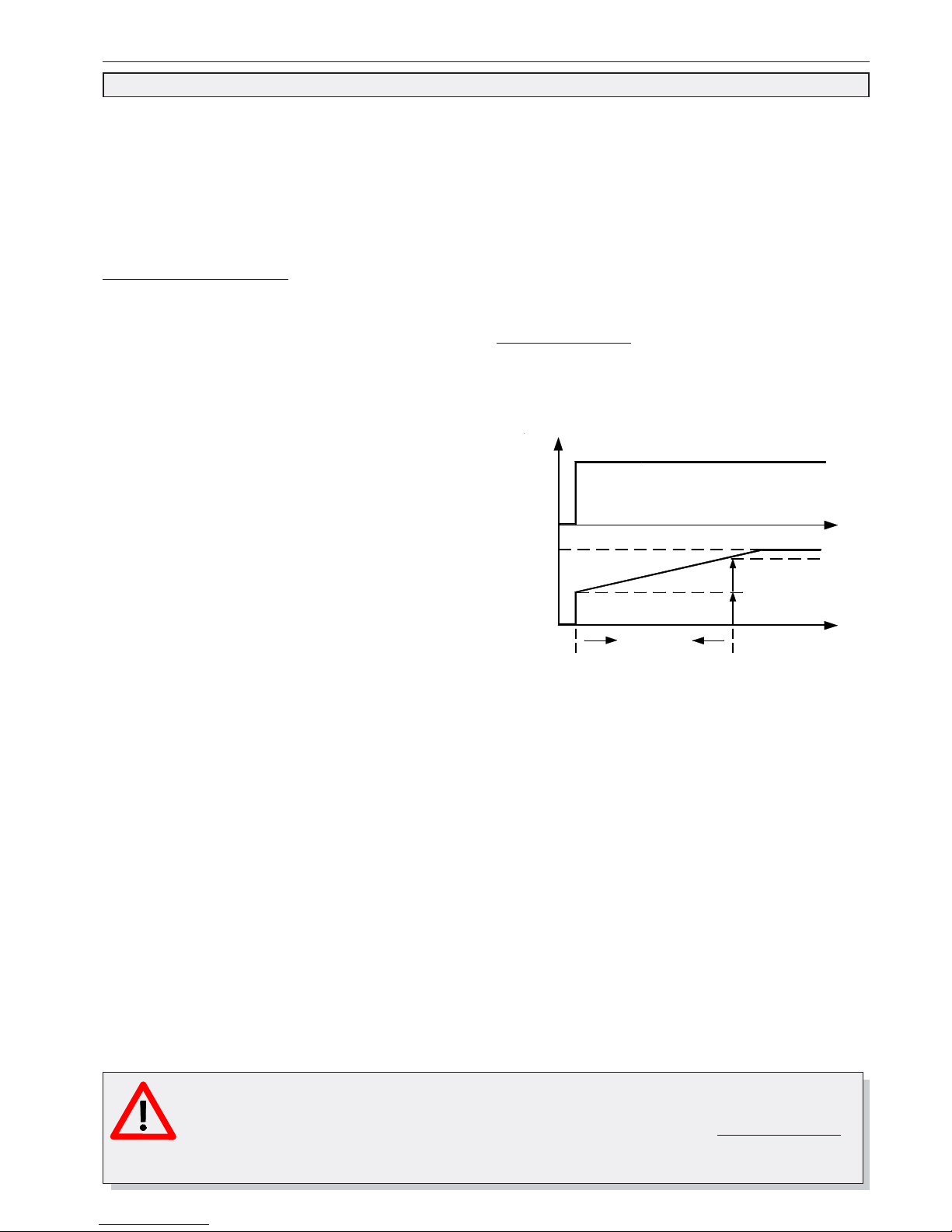
P38.... Fixes the I-part of the output signal in 5 steps from appr.
0,25...4 minutes or switches it off.
Analog Output Operation Mode
P39 fixes the operation mode of the output.
P39 = 0 Output is de-activated.
P39 = 1 Output effects proportional, that's to say increasing
actual value -> increasing output voltage
P36/P37 are absolute values.
P39 = 2 Output effects anti-proportional, that's to say
increasing actual value -> decreasing output
voltage
P36/P37 are absolute values.
P39 = 3 Output effects proportional, that's to say increasing
actual value -> increasing output voltage.
The values set by P36/P37 effect relative to the
current setpoint (P03 + shift).
Example:
P36 = 10°C, P37 = -10°C
P39 = 3, P03 = 15°C, no current shift
Output-:
10V at P03 + P36 = 25°C
voltages
0V at P03 - P37 = 5°C
P39 = 4 Output effects anti-proportional, that's to say
increasing actual value -> decreasing output
voltage.
The values set by P36/P37 effect relative to the
current setpoint (P03 + shift).
Example:
P36 = 10°C, P37 = -10°C
P39 = 3, P03 = 15°C, no current shift
Output-:
0V at P03 + P36 = 25°C
voltages
10V at P03 - P37 = 5°C
Example Actual Value Image:
You have a remote display or similar which shows -50°C at 0V
input voltage and +50°C at 10V DC.
P37 = "-50", P36 = "+10", P39 must be "1" .
Example Proportional Controller:
You want to control any device with 0-10V-input depending on
pressure. You want it to be half open at 5.0 bar. If pressure
descends the device should go more open, fully open from 4 bar.
If pressure increases the device should closed, from 6 bar it must
remain closed.
P37 ="4.0", P36 ="6.0", P39 ="2"
Slow-down time / I-part
P38 (slow-down time) fixes the influence of the I-part to the control
process. The amount of the I-part of the controlling variable is
identical with the P-part and will be added. The full size of the I-part
will effect after P38 is run down.
Example: - 10V U
out
at +10°C, 0V U
out
at -10°C
- aimed setpoint 0°C = 5V U
out
- current actual value 0°C
Actual value increases by 2K ->
-U
out
rises to 6V immediately
-U
aus
rises farther, after P38 is run down 7V will be
reached.
controlling
variable
slow-down time
P38
max.
setpoint-
deviation
t
P-part
I-part
t
TAR 1260 and Servo Drives / Actuators
Actuators work with 24V AC mostly and so you get the thought to supply actuator and controller from the same
source. Unfortunately, supply voltage and control input are not isolated in actuators, this may destroy the TAR 1260.
Because of this:
If a TAR 1260 must control a servo drive, the TAR must be supplied by an own, separate transformer !
Page 10
Page 10
Technical Manual Temperature-, Humidity-, Pressure-Controller TAR x260
28 (1.1)
16
7
75 (2.95)
rear view with mounting frame
4123 56
19202122 17188915 14
1110
1213
37 (1.46)
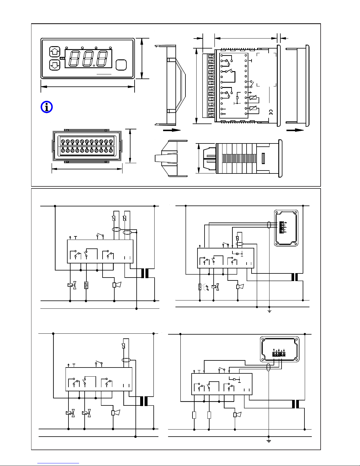
Dimensions TAR 1260
Connection Examples (simplified)
ELREHATAR
76 (3.0
)
123
35 (1.38)
P
4
PE
N
L
17823456 11910
12
230/24V,
5 VA
1624
0..10V
DO
NDO
171823 21 20
1922
K4
K1
K2
OK 1
14
AC/DC
12-24V
15 13
TAR 1260
outdoor sensor F2
control sensor F1
PE
N
L
17823456 11910 12
230/24V,
5 VA
1624
0..10V
DO
NDO
171823 21 20 1922
K4
K1
K2
OK 1
Regelfühler F1
14
AC/DC
12-24V
15 13
TAR 1260
refrigeration/heating, outdoor temperature guided
Basic settings:
P14=3, P07=1, P08=3,
P26=1...4
refrigeration 1/ refrigeration 2
Basic settings:
P14=2, P07=1, P08=1, P26=1...4
2-stage pressure controller
Basic settings:
P14=2, P07=1, P08=1,
P26=5, P29/P30=depends on transmitter
Moisturize / de-humidifying
basic settings:
P14=2, P07=1, P08=3, P26=5,
P29=100, P30=0
Temp.Feuchte.Druckregler
Temp.Hum.Press.Control
70 (2.76)
5
9
Alarm K4
F2
11
12-24V
AC/DC
F1
12
13
10
14
15
4..20mA
7
8
6
16
17
18
19
OK1
12
(.47)
56 (2.2)
4
1
2
3
20
21
DO
NDO
22
23
24 0-10V
K1
K2
+12V
ELREHA
3 (.12)
At controllers which are produced before 3/2002,
terminal 22 delivers no voltage for transmitter
supply !
12-24V
11
AC/DC
10 12
1415 13
51234
+ 0-10V
+ 15-32VDC
+ 4-20mA
230/24V,
5 VA
4..20mA
PE
N
7456213 98
entfeuchten
befeuchten
L
18
DO
NDO
21 20
19
K2
OK 1
0..10V
24 23
22
K1
1617
K4
TAR 1260
12-24V
11
AC/DC
10 12
1415 13
230/24V,
5 VA
Fühler F2
+ 4-20mA
+ 15-32VDC
+ 0-10V
4321 5
4..20mA
PE
N
7
18
456213
DO
NDO
21 20
19
K2
OK 1
0..10V
24 23
22
K1
98
1617
K4
L
TAR 1260
Page 11
Technical Manual Temperature-, Humidity-, Pressure-Controller TAR x260 Page 11
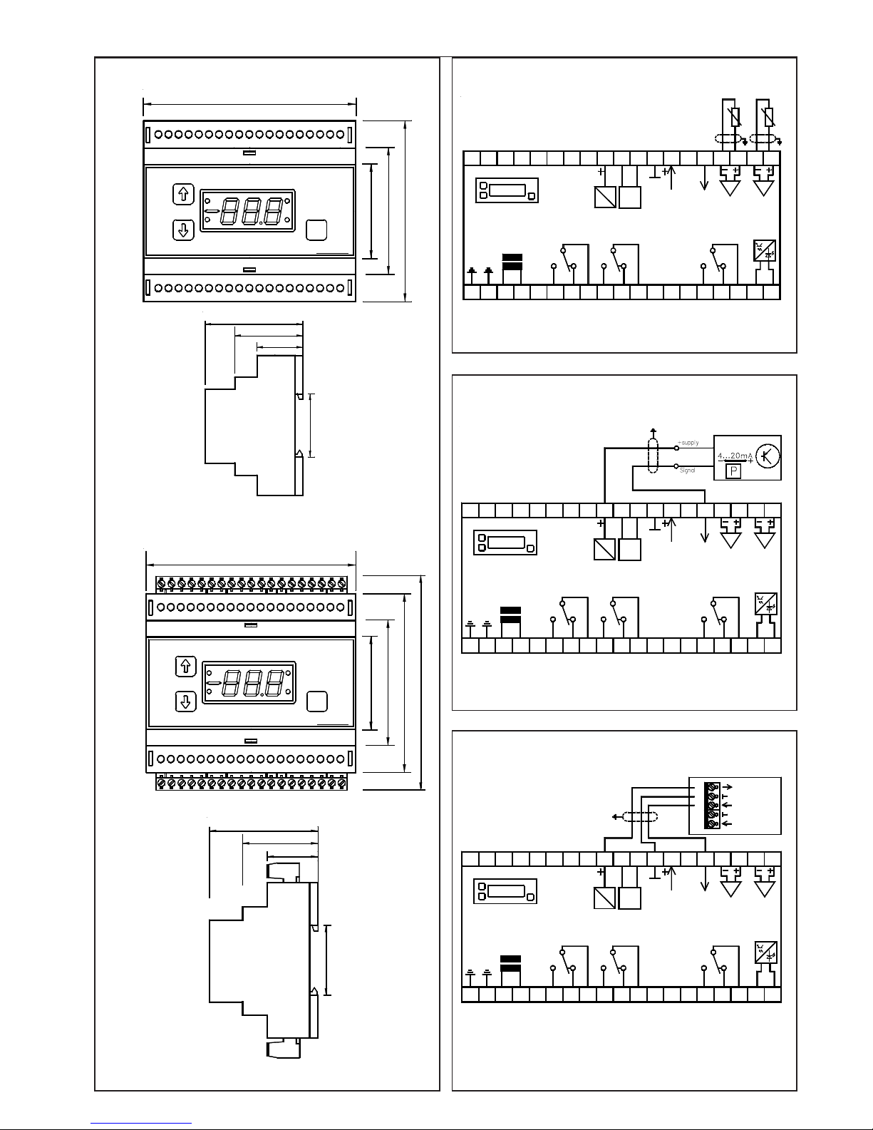
Dimensions TAR 3260 Temperature Sensor Connection TAR 3260
35(1.38)
39 (1.54)
26 (1.02)
59 (2.32)
Humidity Transmitter Connection TAR 3260
46 (1.81)
63 (2.48)
91 (3.58)
ELREHA
12345 76 1089 1211 13 14 15 16 17 18
2 4
P
19
13
27232220 21 25 2624 2928 3130 32 3433
105 (4.13
)
35 36 37 38
TAR
Pressure Transmitter Connection TAR 3260
AC
mains
2
1 3 54 768
rela
y
K1
21
TAR 3260
20 2422 23 2625 27
rela
y
K4
(
alarm
)
151210 119
rela
y
K2
1413
N
OK 1
L
1816 17 19
3431
RS
485
DC
29 3028
NDO
DO
0-10V DC
4-20 mA IN
3332
sensor 1
sensor 2
3735 36 38
DG x/xx
29
10
relay K2
AC
321 54
mains
TAR 3260
76 8 9
relay K1
2422
2120 23 2625
DO
DC
27 28
0-10V DC
RS
485
sensor 1
sensor 2
4-20 mA IN
1511 12 1413 1716
NL
1918
relay K4
(alarm)
OK 1
34
NDO
30 31 3332 3635 3837
29
10
relay K2
DC
521 3 4
TAR 3260
mains
76 8 9
relay K1
AC
242120 22 23 2625 27 28
DO
0-10V DC
sensor 1
sensor 2
4-20 mA IN
1511 12 1413
RS
485
16 17
NL
1918
relay K4
(alarm)
OK 1
3430 31
NDO
3332
5
3
4
1
2
35 36 3837
+ 15-32VDC
+ 4-20mA
+ 0-10V
39 (1.54
)
59 (2.32
)
35(1.38)
26 (1.02
)
1234 95768 1211 1310
2
TAR
232220 21 28
1
24 2725 26 3229 3130
105 (4.13
)
46 (1.81)
63 (2.48)
91 (3.58)
115 (4.53)
181514 16 17 19
ELREHA
P
4
37
3
3433 35 36 38
Hardware version with pluggable connectors
Page 12
Page 12
Technical Manual Temperature-, Humidity-, Pressure-Controller TAR x260
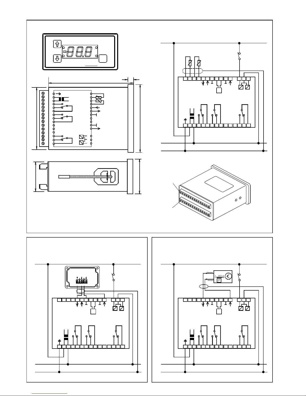
Dimensions TAR 5260
119 (4.69)
N
7
92 (3.62)
15
13
14
10
12
11
9
8
OK 1
relay K4
(alarm)
OK 2
relay K2
6
5
2
4
3
1
relay K1
mains
PE
22
97 (3.81)
GND
+20V DC f.
transmitter
485 NDO
30
28
29
25
26
23
24
GND
485 DO
0-10V= OUT
4-20 mA IN
sensor 2
sensor 1
21
20
17
18
19
16
8
1
3
ELREHA
2
P
4
TAR
N
PE
8
23
NDO
DG x/xx
1 25643 7
+4-20 mA
+0-10V
PE
mains
relay K
1
relay K
2
L
16 2217 18 212019
139 10 1211 1514
RS
485
DO
N
OK 1
OK 2
+20V DC f.
transmitter
relay K
4
(alarm
)
24 2625 28 29 30
+20V DC f.
Geber
N
PE
L
1 25643 87910 11
PE
+4-20 mA
+0-10V
RS
485
NDO
DO
mains
relay K
1
relay K
2
16 2217 18 212019 23 24 2625
51234
+ 0-10V
+ 15-32VDC
+ 4-20mA
1312 1514
N
OK 1
OK 2
relay K
4
(alarm
)
28 29 30
N
PE
14
29
L
1 1325643 87910 1211
PE
+4-20 mA
+0-10V
RS
485
NDO
DO
N
OK 1
+20V DC f.
transmitter
relay K
1
relay K
2
relay K
4
(alarm
)
mains
16 2217 18 212019 23 24 2625 28
sensor 1
sensor 2
15
OK 2
30
Temperature Sensor Connection TAR 5260
Humidity Transmitter Connection TAR 5260 Pressure Transmitter Connection TAR 5260
45 (1.77)
49 (1.93)
Panel housing acc. to DIN 43700 / IEC 61554
cut-out: 92 x 45 mm (w x h)
tolerances max: +0,8 (w), +0,6 (h)
1
2
1
3
1
4
1
5
2
3
2
4
2
5
4
5
6
7
8
9
1
0
1
1
2
6
2
7
2
8
2
9
3
0
1
1
6
1
7
1
8
1
9
2
0
2
1
2
2
2
3
1
16
Page 13
Technical Manual Temperature-, Humidity-, Pressure-Controller TAR x260 Page 13
2,5 162,5
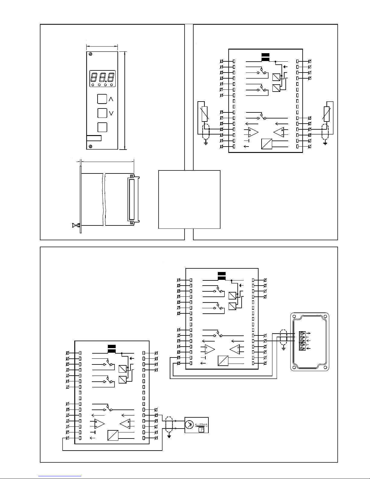
Dimensions TAR 19260
- Wiring diagram shows
a connector equal to
DIN 41612, type 'F',
rear view.
- The 'terminal' numbers are
used in ELREHA's prewired subracks.
ELREHA
P
129
1 243
40,3 (8TE
)
TAR
Temperature Sensor Connection TAR 19260
Humidity Transmitter Connection TAR 19260
Pressure Transmitter Connection TAR 19260
0-10V DC
F1
16
+20VDC
18
32
26
28
30
24
22
20
11
12
16
17
23
21
22
d
14
7
10
5
12
6
8
4
6
2
4
N
2
3
L
terminal
relay 1
relay 2
sensor 1
16
sensor 2
18
32
RS485
30
26
28
24
22
20
DO
NDO
F2
13
19
18
4/20mA
20
24
25
relay 4
(alarm)
z
14
OK2
10
12
8
15
6
2
4
OK1
N
1
PE
14
terminal
0-10V DC
F1
4
2
22
23
+20VDC
17
26
28
32
30
21
22
24
16
8
4
5
10
14
16
20
18
12
11
12
7
6
6
3
relay 1
relay 2
2
d
N
L
terminal
4
PE
22
20
19
26
28
32
RS485
30
DO
NDO
24
25
24
F2
18
4/20mA
+Vers.
Signal
8
15
10
14
16
20
18
13
OK2
12
6
OK1
14
relay 4
(alarm)
DG x/xx
2
z
N
1
terminal
0-10V DC
F1
18
+20VDC
24
23
28
17
32
30
21
22
26
16
22
20
11
12
terminal
4
2
6
3
5
10
14
16
12
7
6
8
4
2
d
N
L
relay 1
relay 2
18
24
20
28
19
32
RS485
30
DO
NDO
24
25
26
F2
18
4/20mA
22
20
13
relay 4
(alarm)
2
+ 0-10V
5
4
+ 4-20mA
3
+ 15-32VDC
1
terminal
4
PE
6
OK1
14
10
14
16
OK2
12
8
15
2
z
N
1
Page 14
Page 14
Technical Manual Temperature-, Humidity-, Pressure-Controller TAR x260
Start-up example: Dual Channel Temperature Controller
Requirements:
Cooling ON at +10°C/ OFF at +9°C, Heating ON at +1°C/OFF at +2°C, the
offset Heating/Cooling remains always equal, Overtemperture Alarm at
+15°C, Undertemperature Alarm at 0°C, both after 30 minutes.
The alarm relay works active-low. At a certain time the setpoint must be
increased by 2K (night operation).
The controller works with the temperature sensor TF 201. The customer
must be prevented from adjusting the setpoint lower than 0°C.
• Please always note safety instructions on page 2!
If the TAR is switched ON, the display shows the value of sensor input 1.
Enter code number "70" at parameter P43
• P26= 1, Sensor Type TF 201 and display in °C
• P14= 2, Operating mode with 1 control sensor (F1) only
Enter code number "88" at parameter P43
• P03= 9.0 (cooling setpoint, relay K1)
• P04= -7.0 (heating setpoint 7 K below P03, relay K2)
• P05= 2 (heating setpoint is relative value, coupled to the cooling
setpoint)
• P06= 2.0 (cooling setpoint will be increased by 2K while night
operation)
• P07= 1 (relay K1 will be activated with rising temperature)
• P08= 3 (relay K2 will be activated with falling temperature = Heating)
• P09= 1 (alarm relay K4 will be de-activated with an alarm)
• P10= 15 (the setpoint cannot adjusted higher than +15°)
• P11= 0 (the setpoint cannot adjusted lower than 0°)
• P12= 1 (hysteresis of cooling relay, 1K)
• P13= 1 (hysteresis of heating relay, 1K)
• P31= 30 (alarm delay 30 minutes)
• P32= 5 (overtemperature alarm 5 K higher than cooling setpoint)
• P33= 0 (underemperature alarm at 0°)
• P34= 1 (digital input open = night shift)
• P35= 0 (night shift works immediately)
Display Correction
The Actual Value Display P01 can be adjusted by P27, the Actual Value
Display P02 can be adjusted by P28.
Start-up example: TAR as Humidity Controller
Requirements:
De-humidifying ON at 80% r.H., Moisten ON at 60% r.H., hysteresis 2%,
both setpoints are absolute values, no alarm, no night shift.
The controller must work with the humidity transmitter FF 2520.
No setpoint limitation for the customer.
The customer want to read the humidity value on a remote display with 010V-input.
• Please always note safety instructions on page 2!
If the TAR is switched ON, the display shows the value of sensor input 1.
Enter code number "70" at parameter P43
• P26=5, Transmitters with 4-20 mA signal
• P14=2, Operating mode with 1 control sensor only
Enter code number "88" at parameter P43
• P03=78.0 (de-humidify setpoint, relay K1)
• P04=62.0 (moisten setpoint , relay K2)
• P05=1 (setpoints are absolute values)
• P06=0 (no setpoint shift)
• P07= 1 (relay K1 will be activated by rising humidity = de-hum.)
• P08= 3 (relay K2 will be activated by falling humidity = hum.)
• P10= 100
• P11= 0
• P12= 2 (hysteresis for de-humidifying relay, 2%)
• P13= 2 (hysteresis for moistening relay, 2%)
• P29= 100 (display value with 20 mA current input)
• P30= 0 (display value with 4 mA current input)
• P34= 0 (Digital input disabled)
• P36= 100 (Analog output delivers 10V DC at 100% r.H.)
• P37= 0 (Analog output delivers 0V at 0% r.H.)
• P39= 1 (operating mode of analogue output)
Display Correction
The actual value display P01 can be adjusted by P27.
Installation hint:
If the measured values 'jump' check the following: Is the shielding of the sensor wire connected to PE near the controller unit? Is the PE
terminal of the controller unit connected to PE? If the sensor wire is shielded correctly but the value on the display continues 'jumping', please
try to solve the problem by removing the shield from PE and connecting it to a ground terminal of the TAR.
EG-Statement of Conformity
*The conformity with IEC 1000-4-3 is derived from the IEC 1000-4-2 and IEC 1000-4-4 test results. The correlation with IEC 1000-4-3 is based on test results which
are located on site at the manufacturer.
We state the following: When operated in accordance with the technical manual, the criteria have been met that are outlined in the guidelines
of the council for alignment of statutory orders of the member states on electro-magnetic consistency ( 89/336/EWG ). This declaration is valid
for those products covered by the technical manual which itself is part of the declaration. Following standards were consulted for the confirmity
testing with regard to electromagnetic consistency :
IEC 1000-4-1, IEC 1000-4-2, IEC 1000-4-3*, IEC 1000-4-4, IEC 1000-4-5, EN 55011 B, EN 50081, part 1 and 2;
EN 50082, part 1 and 2, EN 61010 part 1, EN 61010-1/A2 part 1/A1
This statement is made from the manufacturer / importer by:
ELREHA Elektronische Regelungen GmbH Klaus Birkner, Developement and
68766 Hockenheim, Germany and leader of the EMC-Laboratory
(Name / Anschrift /
name / adress
)
Hockenheim 12.3.98 .............................................
Ort/
city
Datum/
date
Unterschrift/
sign
This manual, which is part of the product, has been set up with care and our best knowledge, but mistakes are still possible.
Technical details can be changed without notice, especially the software. Please note that the described functions are only valid for units containing
the software with the version-number shown on page 1of this manual. Units with an other software number can work a little bit different. You will
find this number on the type label.
set up 23.2.05, tkd/jr checked: 23.2.05, ek/al approved: 23.2.05, mv/sha
 Loading...