

Page 1
Cold Storage Controller
with cyclic defrost
T AR 1370
T AR 1370 H
ELEKTRONISCHE REGELUNGEN GMBH
Manual No. 5311009-05/04 E
Software Version 011118
Product Description
Cold Storage Controller with 4 relays for Solenoid Valve, Defrost
heater, Fan and Alarm Forwarding. Usable for any kind of cold
storages such as walk-in coolers/freezers, refrigerated shelfs,
refrigerated counters, etc..
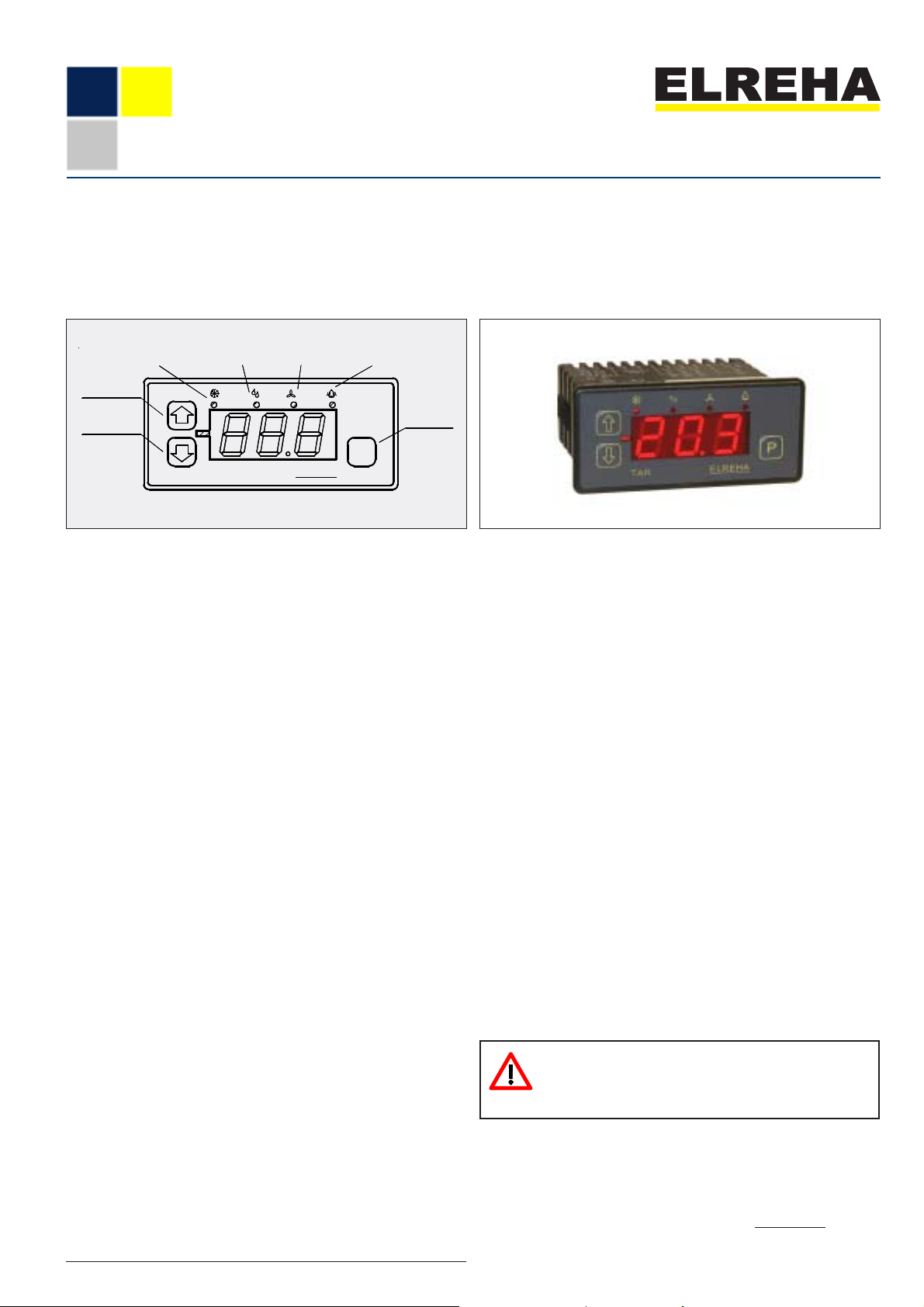
Operating Elements
increase
values
decrease
values
refrig. ON
defrost ON
alarmfan ON
Programming /
enter
P
TAR
Parameters
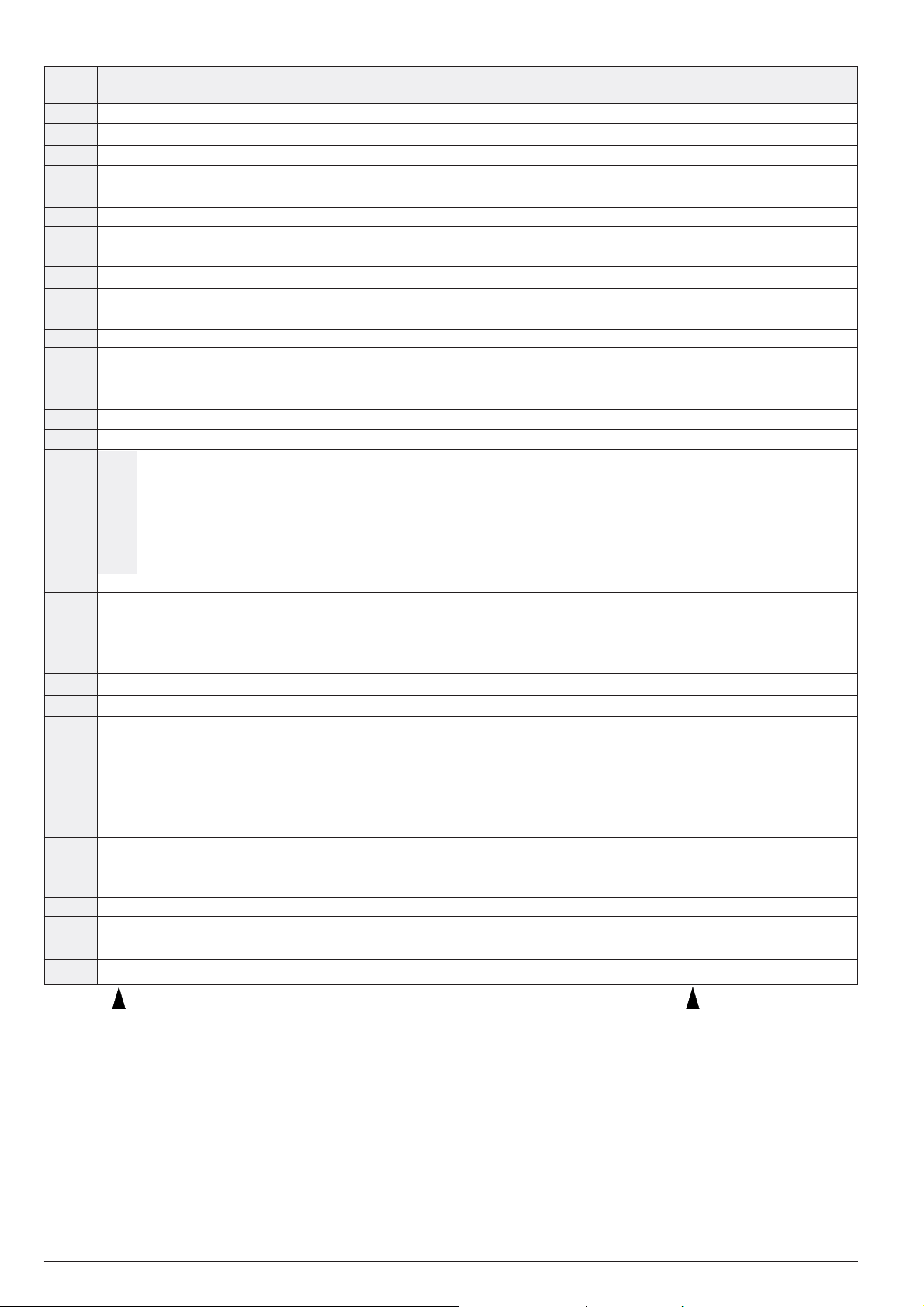
All selectable parameters hold a parameter number (e.g. P03), you
will find a listing on the next page.
Calling up and editing
Press key 'P' ............ parameter number appears
Use '!/"'................. select desired parameter
Press "P" again ........ parameter value appears
Use keys '!/"'......... adjust parameter value
Press 'P' again ......... value is stored, back to parameter no.
Unlock Keys
To prevent un-authorized persons from editing parameter values, there is
a locking function which allows only the most important parameters to be
changed at any time. All other parameters must be unlocked beforehand.
Press key "P" ............. parameter number appears
Use "!/"" ................. select code parameter (P38)
Press "P" again.......... parameter value appears
Use "!" ..................... set value to --88--
Press "P" again.......... value is stored, back to parameter no.
If no key is hit for abo
ut four minutes, the access code is cancelled and
the editing function is locked automatically.
Auto scrolling
Hold '!/"'-keys to scroll values automatically.
Manual Defrost
Manual defrost can be initiated out of programming mode by depressing
'!' for more than 2 seconds - to terminate: press '"' for more than 2
seconds.
Reading the controller type
Hold key 'P' for more than 2 seconds, the display shows the type of
the controller unit (137).
Set parameters to factory default
- Switch off supply voltage, press and hold the 'P'-key
- switch on supply voltage
- hold the key for about 5 more seconds
While holding the key, the display shows one by one: softwareversion, date and 'def.'. 'def' signifies that all parameters are set to
default values now.
Reset internal Beeper (TAR 1370 H only)
The internal beeper can be reset by any keypress.
ELREHA
Start-up / Troubleshooting information you will find
on pages 4 + 5.
Technical Data
Supply V o l t a g e ..................................... 12V AC/DC (11-18V DC)
Power Consumption ....................................................appr. 3 VA
Contact Rating Cooling Relay .......... 10 A (peak 80 A / 10 msec)
other relays.......... 8A cos phi = 1, 3A ind. / 250V
The current over terminal 7 may not increase 12 A !
Operating temperature ............................ -10...+55°C (14...131°F)
Storage temperature .............................. -30...+70°C (-22...158°F)
Relative Humidity ......................... max. 80% r.H., not condensing
Display........... LED, 7-segment, red, character height 13mm (.51)
Resolution................................................................ 0,1°C / 0,2°F
Accuracy...................................................................... typ. +/- 1K
Temperature sensors............ TF 201, TF 202 or TF 501 (Pt1000)
Control-/Display Range
with TF 201/202........................ -55...+105°C / -67...221°F
with TF 501 .......................... -110...+120°C / -166...248°F
Data storage parameters .........................................typ. unlimited
Relay i n d i c a t o r s ........................................................... 3 mm, red
Beeper (TAR 1370 H only)..................................... 2x per second
Electrical connection ...............................screw terminals 2,5mm²
Protection ............................................................ IP 54 from front
Accessories (please order separately)
Temperature sensors ................................. 2x TF 201 or TF 501
Transformer ..........................107-1300-0052 (230V/ 12V / 5VA)
Please Note Safety Instructions !
Please note supply voltage when
replacing older types !
Please read this manual carefully before using the product. The guarantee will lapse in case
of damage caused by failure to comply with these operating instructions! We shall not be liable
for any consequent loss! We do not accept liability for personal injury or damage to property
caused by inadequate handling or non-observance of the safety instructions! The guarantee
will lapse in such cases. This manual, which is part of the product, has been set up with care
and our best knowledge, but mistakes may occur. Technical details can be changed without
notice, especially the software. Please note that the described functions are only valid for units
containing the software version-number shown on page 1.
D-68766 Hockenheim, Germany,
phone 0 62 05 / 2009-0 - fax 0 62 05 / 2009-39 - [email protected]
ELREHA Gmbh
Schwetzinger Str. 103
Page 2
page 2 Technical Manual TAR Cold Storage Controller TAR 1370
Param. Code Description Range Default Your value
No. onl.
P01 Actual temperature control sensor (°C or °F) display only
P02 Actual temperature evaporator sensor (°C or °F) display only
P03 no Setpoint Low limit P08...high limit P07 0 °C
P07 88 Highest adjustable setpoint ± 100 °C (-148...212 °F) +50 °C
P08 88 Lowest adjustable setpoint -100°C / -148°F up to (P07) -50°C
P09 88 Setpoint hysteresis 0,3...20,0 K 2 K
P10 88 Switching mode cool. (compressor) relay 1= refrigeration, 2= heating 1 (refrig.)
P11 88 Cooling relay idle time 0...59 minutes 2 minutes
P12 88 Fan operation threshold -100°C... +100°C (hyst. 3K fixed) 50°C
P13 88 Fan operating mode 1=, 2=, 3=, see text 1
P14 88 Fan delay after defrost 0...30 minutes 3 minutes
P15 Remaining minutes till defrost ends display only
P16 Remaining minutes to activate cooling display only
P17 Remaining minutes to start fan relay display only
P18 Remaining minutes up to an alarm display only
P19 88 Calibration control sensor +/-10,0 K/F 0 K
P20 88 Calibration evap. sensor, resp. sensor OFF +/-10,0 K/F, oFF 0 K
P21 70 Sensor type / °C or °F / measuring range 1= TF 501 / °C / -110...+120°C 2
2= TF 201 / °C / -55...+105°C
3= TF 501 / °F / -166...248°F
4= TF 201 / °F / -67...221°F
5= TF 202 / °C / -55...+105°C
6= TF 202 / °F / -67...221°F
P22 88 Defrost termination temperature in °C or °F 0,0...30,0°C / 118,0°F 10°C
P23 88 Defrost type 1= heater defrost by cyclic timer 1
2= hot gas defrost by cyclic timer
3 = heater defr. by cooling runtime.
4 = hot gas defrost by cooling runtm.
P24 88 Defrost cycle 1...99 hours 4 hours
P28 88 Defrost duration 0...120 minutes 30 min.
P29 88 Drain time (refrigeration delay after defrost) 0...99 minutes 0 min.
P30 88 Alarm mode 0= Alarm relay active ON (N / O)
1= Alarm relay active OFF (N / C)
2= no function
3= no function
4= Alarm relay resettable (see text) 1
P31 88 Alarm delay
1...99 minutes (if sensor fails always
< 1 minute + flashing display)
5 minutes
P32 88 Alarm high limit temperature (relative to P03) 0...100 K 100K
P33 88 Alarm low limit (absolute value) ± 100 °C -100°C
P37 no Manual defrost "!"= Start defrost event
"""= Terminate defrost event
P38 no Access Code 0...99 0
Please note that you need a different code for
changing sensor type.
Default values are factory set values.
Page 3
Technical Manual TAR Cold Storage Controller TAR 1370 page 3
m
Functional Description
Display & Sensors
All temperature values can be displayed in °C or
°F with a resolution of 0,1K (0,2°F). Parameter
P21 allows toggling between these two display
modes and to change the type of sensor.
TF201, TF 202 (PTC) as well as TF501 (Pt1000)
sensors can be used, but note that this results in
different temperature ranges. If not required, sensor 2 (Evap. Limit Sensor) can be disabled.
Temperature Control
The controller compares the actual room temperature (P01) with the control setpoint (P03) and
activates the cooling relay which is able to switch
solenoid valves or compressors.
The switching hysteresis (differential, P09) is adjustable to prevent the system from short cycling.
An idle time (P11) prevents a compressor from
switching ON again immediately.
Setpoint range
With P07/P08 you can limit the setpoint range to
prevent the end-user from entering a critical value.
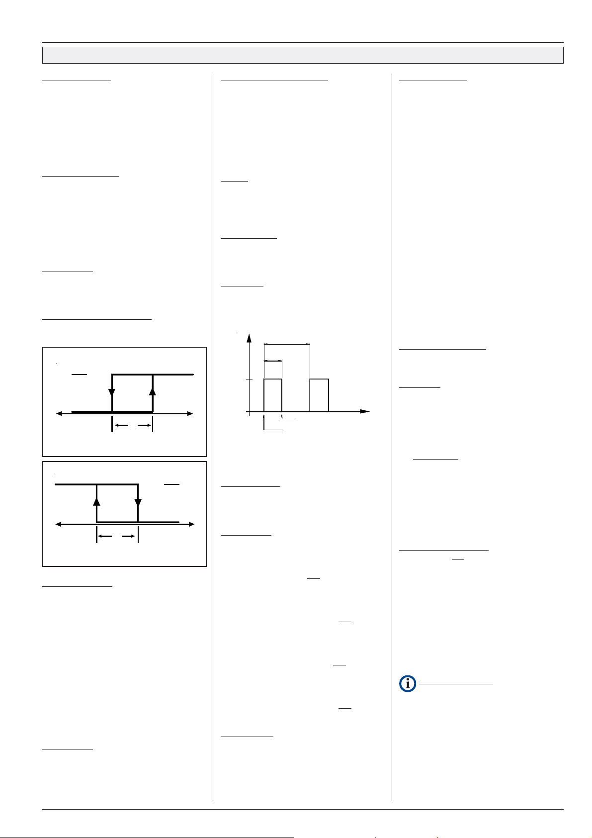
Switching mode of cooling relay
The switching behavior of the cooling relay
(= cooling mode) is defined by parameter P10.
1= refrigeration
activated
de-activated
s
t
cold
2= heating
i
s
n
i
e
o
r
p
e
t
t
e
s
s
y
h
war
activated
de-activ.
s
cold
Temperature alarm
An alarm relay is available for warning purposes.
If the temperature measured by the control sensor exceeds the range set with parameters P32/
P33 a delay timer (P31) starts. After this timer is
run down, the alarm relay will be activated. P32 is
located relative to setpoint P03, so P32 will be
shifted the same size the setpoint will be shifted.
If the alarm mode P30 is set to '4', the alarm relay
can be reset while the temperature is located
within the alarm range.
If the temperature has left the range, P18 shows
the remaining time until an alarm occurs.
If the temperature comes back to the working
range, the relay will be reset automatically.
Alarm Beeper (TAR 1370 H only)
This type owns an internal beeper, which will be
activated together with the alarm output. It can be
reset at any time by any kexpress.
i
s
e
r
e
t
s
y
h
t
warm
n
i
o
p
t
e
s
Alarm relay operation modes
With parameter P30 you select the alarm relay
mode:
0 = Alarm relay active ON
1 = Alarm relay active OFF
2/3= no function
4 = Alarm relay can be reset while tempera-
ture is located within the alarm range.
Can be used to drive an external klaxon.
Defrost
One relay output is able to control a defrost
device. There is no need for external interlocking
the defrost output with the cooling output since the
temperature controller is disabled while defrost.
Defrost Initiation
#
by a cyclic timer (P23 = 1 or 2)
#
by cooling runtime (P23 = 3 or 4)
#
manually (P37).
Cyclic Timer
Parameter P24 defines the time till next defrost
event, P23 defines the defrost duration.
P15 shows the remaining time of the running
defrost cycle until termination by time.
Defrost cycle
Defrost
duration
On
Off
The cyclic timer starts with power-up of the unit,
the first defrost event can start after the first cycle
time has been run down.
Cooling Runtime
If the added runtimes of the cooling relay exceed
the value set by P24, a defrost event will be
started.
Defrost Modes
With P23 a defrost mode can be selected.
1 = Heater or Airflow Defrost by cyclic timer
Starting of defrost event switches ON defrost
relay (i.e heater ON) and switches OFF
the cooling.
2 = Hot Gas Defrost by cyclic timer
Starting of defrost event switches ON defrost
relay (i.e. bypass-valve open) and switches
ON cooling relay (i.e. solenoid valve open).
3 = Heater or Airflow Defrost by cooling runtime
Starting a defrost event switches ON
defrost relay (i.e heater ON) and switches
OFF the cooling.
4 = Hot Gas Defrost by cooling runtime
Starting of defrost event switches ON defrost
relay (i.e. bypass-valve open) and switches
ON cooling relay (i.e. solenoid valve open).
Manual Defrost
#
Parameter P37 allows starting a defrost
cycle with the "!" key, unless the sensor is
already above termination temp. or
#
While the actual temperature can be read on
display, a defrost event can be initiated by
holding the "!" key for more than 2 sec.
Defrost Off
Defrost On
Defrost Termination
#
Thermal termination.
Whenever the evaporator sensor temperature (P02) is warmer than the temperature
limit set with parameter P22, defrosting will
be terminated.
#
Termination by time.
The time set with parameter P28 is the
maximum time a defrost cycle can last before
it is terminated automatically.
#
Manual termination.
With parameter P37 you can terminate a
defrost cycle by pressing """ key.
or
While the actual temperature (P01) can be
read on the display, a defrost event can be
terminated by holding """ key for more than
2 seconds.
# If the defrost limit sensor is interrupted, the
defrost event will be stopped immediately.
After the defrost event is terminated, the begin of
the cooling function is delayed by (P29). This
prevents freezing water drops on the evaporators
surface. P16 shows the remaining time until cooling starts again.
Evaporator Fan Control
Three different modes of fan operation can be
selected with parameter P13.
Fan Modes
1 = Fan runs if compressor output is on.
After defrosting the fan output is OFF until the
programmed Fan Delay Time (P14) is complete. .
2 = Fan runs continously, except during defrost
and Fan Delay Time (P14) after defrost.
Thermostatic fan delay: The fan stops if the
temperature measured with the evaporator
sensor exceeds (P12). If this function is
not desired, P12 can be set to its upper
border to make it inefficient.
3 = Fan runs if the compressor output is on, and
during defrost.
The temporal fan delay must be set to "0".
The end of a defrost cycle
A temporal fan-ON delay is active after a defrost
event (P14).
A thermostatic delay is always active, that means
the fan starts only if the temperature measured
with the evaporator (limit-) sensor is 3K below the
fan operation threshold (P12).
If this function is not desired, P12 can be set to its
upper border to make it inefficient.
While drain time (P29) the fan remains stopped.
(P17) informs about the remaining time until the
fan starts again.
Practical conditions
The fan is always run from the N/O contact of the
fan relay.
If you want to realize a thermostatic delay, select
fan mode 2 and adjust setpoint P12.
If you want to realize a thermostatic delay and free
air defrost, please realize a parallel connection of
fan relay and defrost relay.
Page 4
page 4 Technical Manual TAR Cold Storage Controller TAR 1370
CONNECTION INFORMATION & SAFETY INSTRUCTIONS
Please read before Start-up
The guarantee will lapse in case of damage caused by failure to
comply with these operating instructions! We shall not be liable for
any consequent loss! We do not accept liability for personal injury or
damage to property caused by inadequate handling or nonobservance of the safety instructions! The guarantee will lapse in
such cases.
If you notice any damage, the product may not be connected to
mains voltage! Danger of Life! A riskless operation is impossible if:
• The device has visible damages
• The device doesn't work
• After a long-time storage under unfavorable conditions
• After inadequate shipping conditions
The product may only be used for the described
application.
• Electrical installation and putting into service must be
done from authorized personnel.
• Please note the local safety instructions !
• Before installation: Check the limits of the controller and
your application. Before starting up we recommend you to
read the manual for use, since only by doing so you can
avoid damage or malfunction and you will benefit all the
advantages offered by this product.
• During installation and wiring never work when the
electricity is not cut-off !
• Never operate unit without housing.
• Mounting the controller close to power relays is
unfavourable in case of the electro-magnetic interference.
• Before applying voltage to the controller:
Make sure that all wiring has been made in accordance
with the wiring diagram in this manual.
• Respect the environmental limits for temperature and
humidity. Outside these limits malfunctions may occur.
• Observe the maximum admitted current rate for the
relays (see technical data). Compare with the peak startup current of the controlled devices (fan, compressor,etc.)
• Use shielded cable for sensor elongation only. Don’t install
them in parallel with high-current cables to prevent inductive
interference. A wire gauge of min. 0,5mm² is sufficient.
• Connect shielding to PE at the end near the controller
• All used temperature sensors must be identical. Never
use TF 201 and TF 501 mixed. This will not work.
• TF-type sensors are not designed for being immersed in
water for a long period of time (not pressure-proof). In such
a case, always use dip-fittings.
Installation / Run-Up
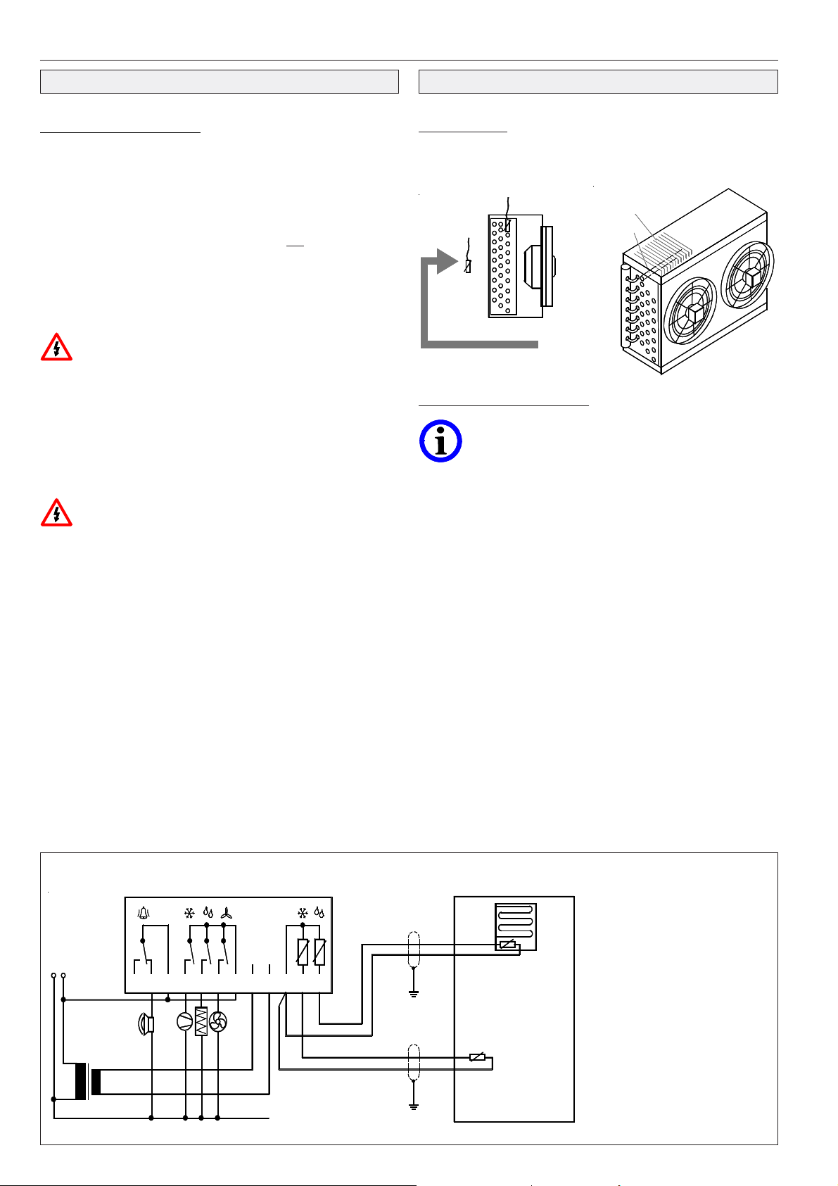
Sensor locations
Control Sensor: In the airflow, at the suction side of the evaporator.
Limit Sensor: In the lamella core or the contact pipe of the evaporator,
at the place ice remains the longest time.
Evaporator(Limit-)
sensor
Control
Sensor
Airflow
lamellacore
contact pipe
Applications with Airflow-Defrost
If this defrost method is used, there is no need for a defrost
sensor in the evaporator, so the sensor can be disabled. If
the correction parameter P20 is set to -10,1, the display
shows "oFF" and the sensor is disabled. Correcting the
parameter upward enables the sensor again.
After power-up, teh display shows the temperature of the control
sensor. After entering the access code (see chapter "unlock keys") you
have to set the basic configuration of the controller to suit your
application:
# kind of temperature sensor and display value (°C/°F)
(P21, Please note: special access code is '70').
# switching mode of cooling relay (parameter P10)
# defrost method (P23)
# evaporator fan mode (P13)
# alarm mode (P30)
# sensor correction if necessary by P19/P20.
The basic setup is now complete and you can edit the missing
setpoints, delay times etc.
See troubleshooting help on next page
Application Example
123
F2
12 V
AC/DC
5467 1089 11
F1
12
evaporator (limit-)
sensor
cold storage
control sensor
Typical parameter values for
a cold storage with heater
defrost
P03 -20
P07 -15
P08 -25
P09 2
P10 1
P11 2
P12 -2
P13 1
P14 3
P22 14
P23 1
P24 4
P28 30
P29 2
P30 1
P31 20
P32 7
P33 -35
Page 5
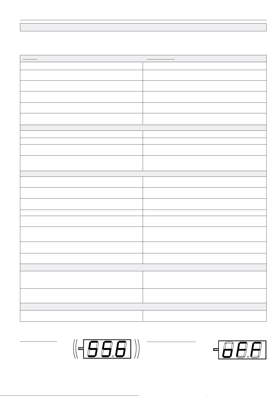
Technical Manual TAR Cold Storage Controller TAR 1370 page 5
Troubleshooting
1. Which controller do you have ?
Hold key 'P' for more than 2 seconds, display shows the type of the
controller unit (137).
2. Do you hold the correct manual ?
problem
Temperature display:
Actual display flashes with "-110" appr. "-166"
Actual display flashes with "-55" appr. "-67"
Actual display flashes with "120" appr. "248"
Actual display flashes with "105" appr. "221"
Temp. display does not match with actual temperature.
Programming:
Setpoint cannot be adjusted
Other values cannot be programmed
Display is running. All 3 positions change from 111 thru 999
You want to set all parameters to default
Temperature Control:
Room temperature is shown too cold. Cooling is OFF although the room is
too hot or: Cooling switches OFF too early.
Cooling is always running, although the room is cold enough and the
indicator LED 1/Cooling is not ON.
Temperature too high, indicator LED '1/Cooling' is ON, but cooling does not
switch ON.
Temperature too high, but cooling does not switch ON.
Cooling works, but fan is OFF.
You have selected fan mode 3, but the fan does not work during a defrost
event.
You have selected fan mode 2, but fan switches ON and OFF during the
cooling phases.
You want to use a thermostatic fan delay, but the fan switches always OFF
if cooling switches OFF.
Defrost:
3. With parameters P01 and P02 such as P15 till P18 (actual
temperatures and running delays) you get a first survey about the
unit's states.
possible reason
Sensor type TF 501 with "°C" appr. "°F" selected,
Short circuit in wiring or sensor itself
Sensor type TF 201 with "°C" appr. "°F" selected,
Short circuit in wiring or sensor itself
Sensor type TF 501 with "°C" appr. "°F" selected,
Wiring or sensor itself broken
Sensor type TF 501 with "°C" appr. "°F" selected,
Wiring or sensor itself broken
Check if reference thermometer is placed at the same position as the
sensor head. Then correct sensors.
High and low limit of the setpoint range are identical
Enter Access Code.
Unit works in selftest mode. Switch power OFF, switch power On again after 15
seconds. Please check sensor corrections now.
Switch power OFF and wait 15 seconds. Hold P-key, switch power ON,
unhand P-key. (The display shows first the software-version and then 'deF'.
Now all parameter values are lost and are set to default.
Sensor 1 and sensor 2 are interchanged, see also above 'Temp.display'
Wrong switching mode or output contact interchanged (cool. relay). Note:
If you change the switching mode, check the correct defrost mode !
Wrong switching mode or output contact interchanged (cool. relay). Note:
If you change the switching mode, check the correct defrost mode !
Check, if a defrost event or the drain time is running.
Check, if 'fan operation threshold' should work and the evaporator tempe-
rature is below the setpoint. Check if the fan delay is running
In this mode the fan delay must be set to '0'. If the evaporator sensor
reaches the "fan operation threshold", the fan will be switched OFF during
the defrost event. (appr. short defrost and fan relay with external wiring).
Adjust "fan operation threshold" to the highest border
.
Set fan mode to '2', adjust "fan operation threshold".
Does not work.
During a defrost event cooling starts.
Alarm:
Constant alarm without a real failure.
Failure Handling
If the display flashes
with 'minus'-LED:
= sensor short circuit.
without 'minus'-LED:
= sensor interrupted
Another possibility is that the sensor is the wrong type or out of its
specified range. The alarm relay will be activated after 1 minute, like
preset with P30.
Check evaporator sensor position. Check defrost method, -times, -safety time
and -termination temperature. Check if fan delay time is too long. Check if fan
runs correctly in cooling phases
Defrost mode is set to 'hot gas'. Please set correctly.
Note: If you change the switching mode, check or select the correct defrost
mode !
Check wiring and alarm mode. Can be set to active or passive.
(active: relay ON; passive: relay OFF).
Control sensor disturbance
If the control sensor fails, all control
functions will be disabled by
de-activating the relay outputs.
Display shows "oFF" if you select parameters P02 or P20 and the
Limit Sensor is disabled.
Page 6
page 6 Technical Manual TAR Cold Storage Controller TAR 1370
)
)
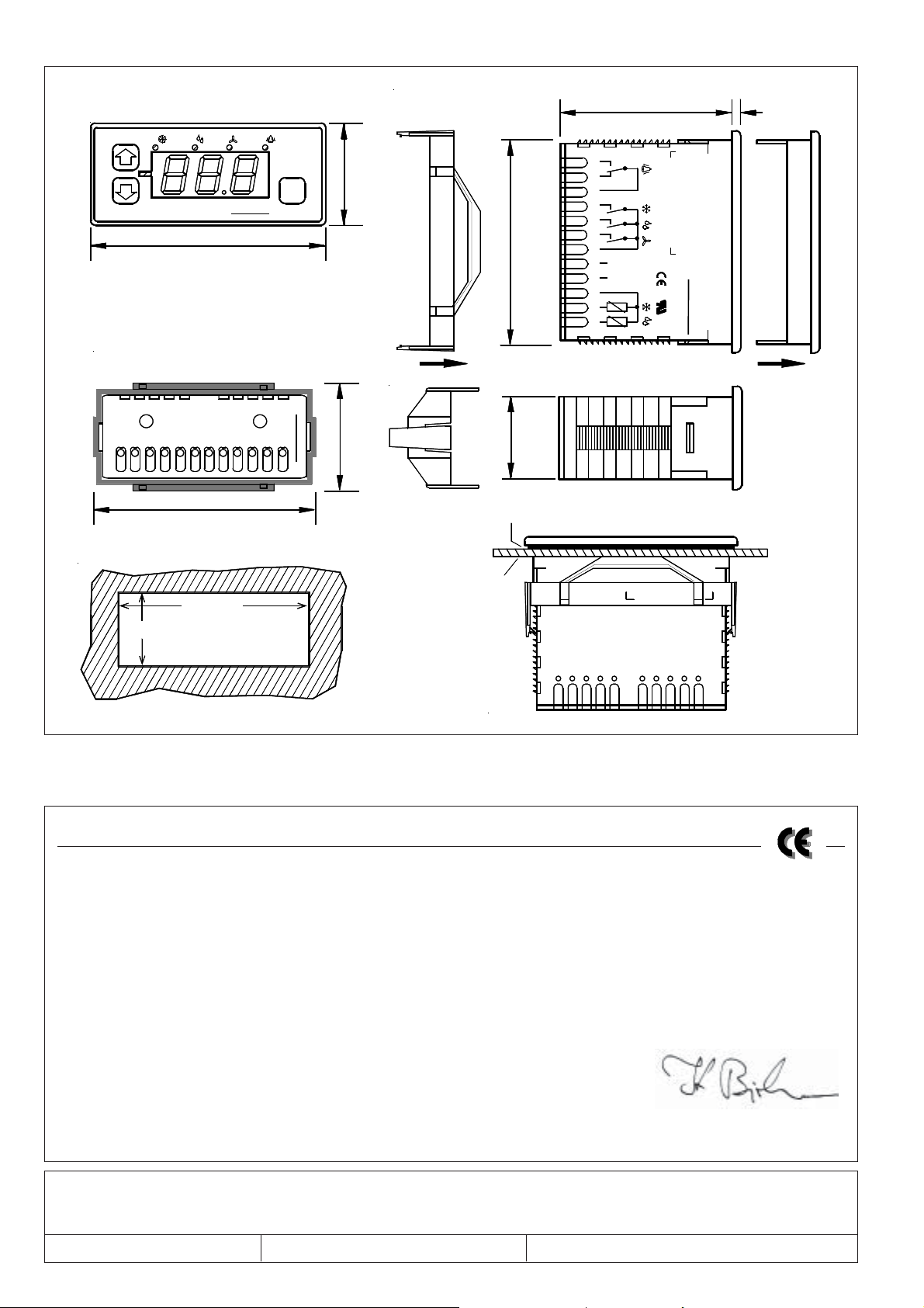
Dimensions / Wiring
56 (2.2)
3 (.12)
1/ 2/ 3/ 4/
TAR
ELREHA
76 (3.0
Rückansicht mit Befestigungsrahmen
rear view with mounting frame
75 (2.95
70 (2.76)
28 (1.1)
cut-out
)
8
3
.
1
(
P
5
3
Snap in fixing frame
from rear side.
)
6
4
.
1
(
7
3
p
mounting
1
2
3
)
6
7
.
2
(
0
7
)
1
.
1
(
8
2
u
i
p
s
l
p
e
g
s
k
a
n
a
e
l
4
5
6
7
A
1
8
C
2
/
D
V
9
C
1
0
1
1
1
2
C
o
l
d
K
S
ü
t
E
h
o
l
r
s
a
L
t
g
e
e
F
1
F
2
R
l
l
C
e
E
o
n
n
r
e
t
H
r
o
g
l
l
A
l
e
e
r
r
Front frame
can be removed
e
d
t
10
9
354
1
2
867
EG-Statement of Conformity
We state the following: When operated in accordance with the technical manual, the criteria have been met that are outlined in the guidelines of
the council for alignment of statutory orders of the member states on electro-magnetic consistency ( 89/336/EWG ). This declaration is valid for
those products covered by the technical manual which itself is part of the declaration. Following standards were consulted for the confirmity testing
with regard to electromagnetic consistency :
IEC 1000-4-1, IEC 1000-4-2, IEC 1000-4-3*, IEC 1000-4-4, IEC 1000-4-5,
EN 55011 B, EN 50081, part 1 and 2; EN 50082, part 1 and 2
This statement is made from the manufacturer / importer by:
ELREHA Elektronische Regelungen GmbH Klaus Birkner, Developement and
68766 Hockenheim and leader of the EMC-Laboratory
(Name / Anschrift / name / adress)
Hockenheim 23.3.2000 .............................................
Ort/city Datum/date Unterschrift/sign
*The conformity with IEC 1000-4-3 is derived from the IEC 1000-4-2 and IEC 1000-4-4 test results. The correlation with IEC 1000-4-3 is based on test results which
are located on site at the manufacturer.
This manual, which is part of the product, has been set up with care and our best knowledge, but mistakes are still possible. If you have any problems,
difficulties or questions please don't hesitate asking our technical support.
Technical details can be changed without notice, especially the software. Please note that the described functions are only valid for units containing
the software with the version-number shown on page 1 of this manual. Units with an other version number may work a little bit different.
set up 19.7.2006/tkd/jr checked: 19.7.2006/ek/al approved: 19.7.2006/mv/sha
 Loading...