

Page 1
Kurzbeschreibung
ELRE HA
P
• Universelle
Fernanzeige für Regler
mit Normsignal-Aus-
gängen (z.B.TKP/TKC-
Kühlstellenregler)
oder anderen Quellen
• Eingänge 1x 0-10V DC
und 1x 4-20mA
• Robustes Gehäuse für
Wandmontage
• Besonders große LED Digitalanzeige (20mm),
dadurch auch aus
größeren Entfernungen
leicht ablesbar
• Automatischer
Anzeigenwechsel
• Über-/Unter-
temperaturalarm für
jeden Eingang
• Alarmverzögerung
• Alarmwiederholung
• interner Alarmsummer
Vorzeichen
Brief Description
• Universal Display or
Remote Display for
controllers with
standardized analogue
outputs (e.g. TKP/TKC
series controllers) or
other sources
• Inputs 1x 0-10V DC
and 1x 4-20mA
• Extra sturdy housing
for wall mounting
• Better reading by
oversized red LED
Display (20mm/.79 in.)
• Automatic interchange
of actual value displays
• Over-/Under-
temperature alarm for
each input
• Alarm delay
• Alarm repetition
• Internal Alarm Beeper
Description
• Afficheur déporté
universel pour
régulateur avec sortie
normalisée (ex. TKP/
TKC-Serie) ou autre
source
• Entrée 1x 0-10V DC et
1x 4-20mA
• Boîtier robuste pour
montage mural
• LED d'affichage grand
format (20mm), pour
une meilleure visibilité
• Inversion automatique
d'affichage entre les 2
entrées
• Seuils haut et bas
d'alarme pour chaque
entrée
• Retard d'alarme
• Répétition alarme
• Buzzer interne
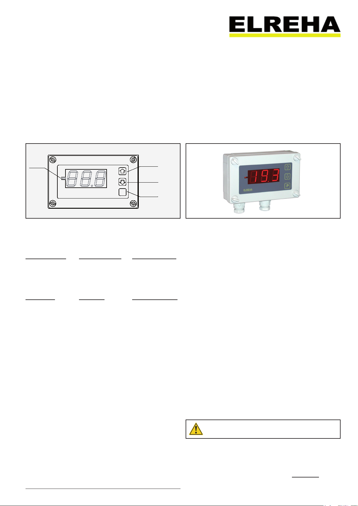
Erhöhen von
Werten
Increase values
Touche pour
augmenter
Programmiertaste
Programming mode
Touche de
programmation
Type:
ELEKTRONISCHE REGELUNGEN GMBH
Betriebsanleitung 5311225-00/042
Operating Instructions
Software Vers. 041021
Notice Technique
Universalanzeige
Universal Display
Afficheur universel
TAA 2140
TAA 22140
Bedienung
Nach dem Einschalten erscheint kurz die Betriebsart
und nach ca. 3 Sek. der
aktuelle Istwert.
Parameter verändern
• „P“, ParamNr. erscheint
• „/“, Param.auswahl
• „P“, Para.wert erscheint
• „/“, Parameterwert
ändern
• „P“, Wert gespeichert,
zurück zur ParamNr.
Zugangsschutz
Alle wichtigen Parameter
sind durch einen Code geschützt. Die Codenummer
wird wie folgt eingegeben:
• "P"-Taste drücken
• Mit „/“
P18 anwählen,
• „P“-Taste erneut,
• "" CodeNr. einstellen
(88)
• "P"-Taste erneut,
ParameterNr. wird
wieder angezeigt
Wird ca. 2 Minuten keine
Taste gedrückt, muß d.
Code erneuert werden,
die Anzeige springt dann
zum Istwert zurück.
Operating
After power-up, the operation mode appears and
after appr. 3 sec. the actual temperature.
Calling up Parameters
• „P“, ParamNo. appears
• „/“, Param. select.
• „P“, Para.value visible
• „/“, Change value
• „P“ again, new value is
stored, back to ParaNo.
Access Code
All important parameters
are protected by an access code. The code can
be entered as follows:
• Push "P"
• Select P18 by „/“
• Push "P" once more
• "" Select CodeNo.
(88)
• Push "P" again
Parameter-No. appears
again
If you don´t press any key
for about two minutes, the
access code is canceled.
Verringern
von Werten
Decrease values
Touche pour diminuer
Utilisation
A la mise en route, le mode
fonctionnement apparaît
puis la température au
bout de 3 sec.
Changer un paramètre
• „P“, n° param. apparaît
• „/“, choisir param.
• „P“, val. param. visible
• „/“, changer valeur
• „P“, nouvelle valeur
validée, retour n° param.
Code de déverrouillage
Pour changer les paramètres, il faut entrer
un code :
• Appuyer sur „P“
• Choisir P18 avec
„/“
• Réappuyer sur „P“,
• „“ Entrer le code
(88)
• Réappuyer sur „P“
Le n° du paramètre
réapparaît.
Si aucune touche n’est
appuyée pendant 2 min.,
l’appareil se reverrouille.
Technische Daten
Betriebsspannung....................................230V AC (47-60 Hz), max. 4 VA
Schutzklasse .....................................................................................IP 54
Summer ............................................................................................75 dB
Betriebs-/Lagertemperatur................................. -10 .. 45 °C / -30 .. 70 °C
Umgebungsfeuchte ...........................max. 85% r.F., nicht kondensierend
Signaleingang 1 ............................0...10V DC, Ri >= 10 kOhm, skalierbar
Signaleingang 2 ...............................4...20mA, Ri <= 110 Ohm, skalierbar
Anzeige.............. 7-Segment LED rot mit Vorzeichen, Ziffernhöhe 20 mm
Gehäuse: ......................................................... Kunststoff, Schraubdeckel
Technical Data
Supply Voltage TAA 2140 ........................230V AC (47-60 Hz), max. 4 VA
TAA 22140 ......................115V AC (50-60 Hz), max. 4 VA
Protection ..........................................................................................IP 54
Internal Beeper .................................................................................75 dB
Operating-/Storage Temperature ....................... -10 .. 45 °C / -30 .. 70 °C
Ambient Humidity .....................................max. 85% r.H., not condensing
Signal Input 1..................................0...10V DC, Ri >= 10 kOhm, scalable
Signal Input 2..................................... 4...20mA, Ri <= 110 Ohm, scalable
Display ..... LED-7-SEg., red, with alg. sign, char. height 20 mm (0.79 in.)
Housing .......................................................plastic, removable upper part
Données techniques
Alimentation .............................................230V AC (47-60 Hz), max. 4 VA
Protection ..........................................................................................IP 54
Buzzer .............................................................................................75 dB
T°c fonct. / stockage .......................................... -10 .. 45 °C / -30 .. 70 °C
Humidité ambiante.................................... max. 85% h.r., non-condensée
Entrée 1 .....................................0...10V DC, Ri >= 10 kOhm, étalonnable
Entrée 2 ........................................ 4...20mA, Ri <= 110 Ohm, étalonnable
Afficheur ...........................7 segments, rouge, Hauteur des digits 20 mm
Boîtier ................................................ Plastique avec convercle vissable
Mechanischer Aufbau
Das robuste Kunststoffgehäuse besteht aus 2
Teilen, das GehäuseOberteil enthält die vollständige Elektronik mit
den Anschlußklemmen.
Das Gehäuse-Unterteil
wird mit der Montageplatte fest verschraubt.
Das Oberteil wird auf
des Unterteil aufgesetzt
und mit vier Knebelschrauben fixiert. Eine
Gummidichtung verhindert das Eindringen von
Feuchtigkeit.
Mechanical Design
Th e stur dy pl ast ic
housing consists of 2
parts, the upper part
contains the electronic
with the connection terminals. The base part is
made for screwing with
the mounting position
like walls or mounting
plates.
The upper part is fixed
on the base part by four
toggle screws.
A rubber gasket prevents
humidity intrusion.
Construction
mécanique
L'ensemble se compose
de 2 parties, le couvercle
avec l'afficheur et la
partie inférieure à fixer au
mûr avec les connexions
électriques.
Le couvercle se visse
ensuite par 4 vis en
plastique.
Un joint permet
d'étanchéifier
l'ensemble.
Bitte Sicherheitshinweise beachten!
Please note Safety Instructions!
Vor Inbetriebnahme diese Bedienungsanleitung sorgfältig lesen! Entstehen durch Nichtbeachtung
Schäden, erlöschen die Garantieansprüche. Diese Dokumentation würde mit größter Sorgfalt
erstellt. Dennoch können wir für die vollständige Richtigkeit keine Garantie übernehmen.
Please read these instructions carefully before applying power. Your attention is drawn to the
fact that the warranty is subject to the application of power sources that are within the limits
specified in this manual. Repairs or modifications made by anyone other than ELREHA will also
void the product warranty. This documentation was compiled with utmost care, however, we
cannot guarantee for its correctnesss in every respect.
D-68766 Hockenheim,
Telefon 0 62 05 / 2009-0 - Fax 0 62 05 / 2009-39 - [email protected]
ELREHA GmbH
Schwetzinger Str. 103
Page 2
Page 2 TAA 2140, TAA 22140
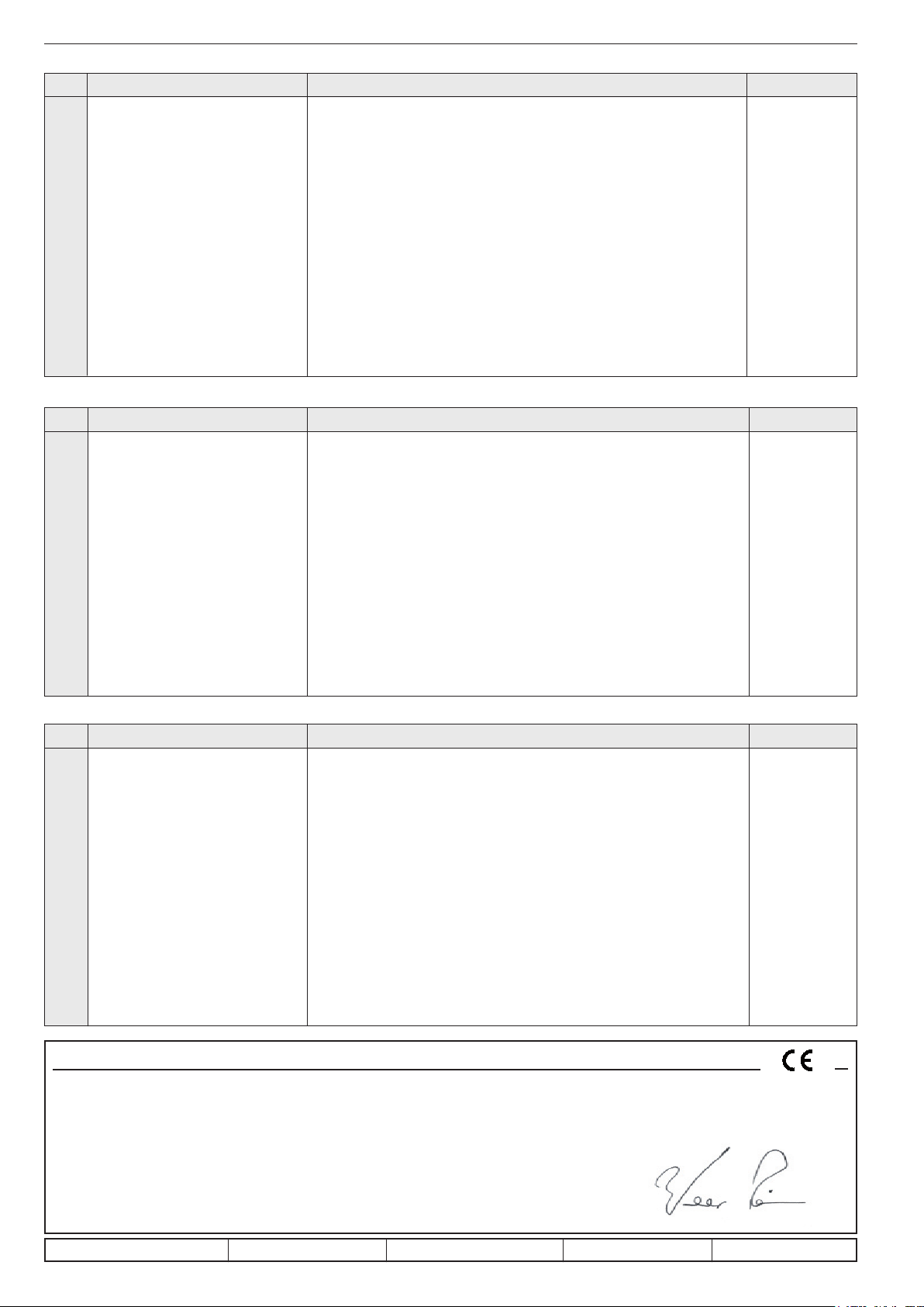
Parameterliste
Nr. Parameter Bereich Werkseinst.
P01 .... Istwert 0-10V-Eingang (F1) .................... -50...300 .................................................................................................................nur Anzeige
P02 .... Istwert 4-20mA-Eingang (F2) ................. -50...300 .................................................................................................................nur Anzeige
P03 .... Anzeigemodus ....................................... 0= ohne Nachkommastelle mit Störungsfilter ........................................................2
1= mit Nachkommastelle und Störungsfilter
2= mit Nachkommastelle ohne Störungsfilter
P04 .... Display Modus .......................................0= normale Anzeige ...............................................................................................0
1= alle 16 Sekunden wird von P01-Anzeige auf P02-Anzeige gewechselt.
Dazu wird jeweils kurz die Parameternummer eingeblendet.
P05 .... Anzeige bei 10V an Signaleingang 1 .....-50...300 .................................................................................................................100
P06 .... Anzeige bei 0V an Signaleingang 1 .......-50...300 .................................................................................................................-50
P07 .... Anzeige bei 20mA an Sign.eingang 2 .... -50...300 .................................................................................................................100
P08 .... Anzeige bei 4mA an Sign.eingang 2 ...... -50...300 .................................................................................................................0
P09 .... Korrekturwert Eingang F1 ......................± 10.0 .....................................................................................................................0
P10 .... Korrekturwert Eingang F2 ......................-10,1...+10.0 (Mit -10.1 ist dieser Fühler abgeschaltet, Anzeige wechselt ............0
dann auf "oFF")
P11 .... Alarm-Obergrenze Eingang F1 ..............-50...+300°C ...........................................................................................................+300
P12 .... Alarm-Untergrenze Eingang F1 ............. -50...P07 ................................................................................................................-50
P13 .... Alarm-Obergrenze Eingang F2 ..............-50...+300°C ...........................................................................................................+300
P14 .... Alarm-Untergrenze Eingang F2 ............. -50...P09 ................................................................................................................-50
P15 .... Alarmverzögerung ................................. 1...99 Minuten ........................................................................................................60 Minuten
P16 .... Alarmquittierungszeit .............................0...99 Minuten (0=keine Alarmwiederholung nach Quittierung) .............................15 Minuten
P17 .... Restlaufzeit Alarm/Quittierung ...............................................................................................................................................Nur Anzeige
P18 .... Zugangscode ......................................... 88 ...........................................................................................................................00
Parameters
No. Parameter Range Factory set
P01 .... Actual value signal input 1 ..................... -50...300 .................................................................................................................display only
P02 .... Actual value signal input 2 ..................... -50...300 .................................................................................................................display only
P03 .... Display Mode .........................................0= without decimal place, with noise filter ..............................................................2
1= with decimal place and noise filter
2= with decimal place, without noise filter
P04 .... Alternating Mode .................................... 0= not alternating ...................................................................................................0
1= every 16 seconds the display changes from P01 to P02.
the parameter number appears always for a short time
P05 .... Display with 10V at signal input 1 ......... -50...300 .................................................................................................................100
P06 .... Display with 0V at signal input 1 ............ -50...300 .................................................................................................................-50
P07 .... Display with 20mA at signal input 2 ....... -50...300 .................................................................................................................100
P08 .... Display with 4mA at signal input 2 ......... -50...300 .................................................................................................................0
P09 .... Correction value for signal input 1 .........± 10.0 .....................................................................................................................0
P10 .... Correction value for signal input 2 .........-10,1...+10.0 (With -10.1, this input is switched off, P02 changes to "oFF") ..........0
P11 .... Alarm upper limit signal of input 1 .......... -50...+300°C ...........................................................................................................+300
P12 .... Alarm lower limit signal of input 1 ..........-50...P07 ................................................................................................................-50
P13 .... Alarm upper limit signal of input 2 .......... -50...+300°C ...........................................................................................................+300
P14 .... Alarm lower limit signal of input 2 ..........-50...P09 ................................................................................................................-50
P15 .... Alarm delay ............................................1...99 minutes ........................................................................................................60 minutes
P16 .... Alarm repetition time ..............................0...99 minutes (0 = no alarm repetition after a reset) .............................................15 minutes
P17 .... Remaining time Alarm/Reset .................................................................................................................................................display only
P18 .... Access Code .......................................... 88 ...........................................................................................................................00
Liste des paramètres
Nr. Paramètre Plage Val. usine
P01 .... Mesure entrée 1 ..................................... -50...300 .................................................................................................................--
P02 .... Mesure entrée 2 ..................................... -50...300 .................................................................................................................--
P03 .... Mode d'affichage .................................... 0= sans 0.1 avec filtrage ........................................................................................2
1= avec 0.1 avec filtrage
2= avec 0.1 sans filtrage
P04 .... Mode display .......................................... 0= Affichage normal ...............................................................................................0
1= toutes les 16 secondes, l'afficheur permute entre P01 et P02, pour
visualiser 2 mesures en même temps
P05 .... Affichage entrée 1 pour 10V .................. -50...300 .................................................................................................................100
P06 .... Affichage entrée 1 pour 0V .................... -50...300 .................................................................................................................-50
P07 .... Affichage entrée 2 pour 20mA ............... -50...300 .................................................................................................................100
P08 .... Affichage entrée 2 pour 4mA ................. -50...300 .................................................................................................................0
P09 .... Correction mesure entrée 1 ................... ± 10.0 .....................................................................................................................0
P10 .... Correction mesure entrée 2 ................... -10,1...+10.0 (en réglant jusqu'à -10.1, l'afficheur ..................................................0
indique "oFF" et l'entrée est inhibée)
P11 .... Seuil haut alarme entrée 1 ..................... -50...+300°C ...........................................................................................................+300
P12 .... Seuil bas alarme entrée 1 ......................-50...P07 ................................................................................................................-50
P13 .... Seuil haut alarme entrée 2 ..................... -50...+300°C ...........................................................................................................+300
P14 .... Seuil bas alarme entrée 2 ......................-50...P09 ................................................................................................................-50
P15 .... Retard d'alarme ..................................... 1...99 minutes ........................................................................................................60 minutes
P16 .... Temps avant répétition alarme ...............0...99 minutes (0=pas de répétition alarme après acquittement) ...........................15 minutes
P17 .... Temps restant avant alarme .................. affichage seul.
P18 .... Entrée code de déverrouillage ...............88 ...........................................................................................................................00
In doing so,
EG-Statement of Conformity
We state the following: When operated in accordance with the technical manual, the criteria have been met that are outlined in the guidelines of the
council for alignment of statutory orders of the member states on EMC-Directive (2004/108/EC) and the Low Voltage Directive (LVD 2006/95/EC).
This declarations are valid for those products covered by the technical manual which itself is part of the declaration. To meet the requirements, the
currently valid versions of the relevant standards have been used
This statement is made from the manufacturer / importer by:
ELREHA Elektronische Regelungen GmbH Werner Roemer, Technischer Leiter, Technical Director
D-68766 Hockenheim
www.elreha.de Hockenheim.............15.04.2009.......................................................
(Name / Anschrift /
original set up: 14.4.09, tkd/jr checked: 15.4.09, ek/ha approved: 15.4.09, mkt/sha transl.(E): korr: 3.9.15, tkd/jr
name / adress) Ort/city Datum/date Unterschrift/sign
Page 3
Anzeige
+ 0...10V
+ 4...20mA
PE
N
L
F2 F1
L
N
+ 0...10V
TAA N 21 xx
P E
N
L
R S
48 5
R ela y 4
4
L
Ma ins
321
N
GN D
P E
765
R ela y 1
TKP 31 xx
11
1098
R ela y 2
14131 2
R ela y 3
4241403 9
OUT
R S
23 2
DO
IN
GND
4...20mA
Output
0...10V
Output
R ela y 6
18
R ela y 5
15 1716 212019
DI 1
DI 2
DI 3
DI 4
25
22
23 24 2826 2 7
F 5
4443 4948474 645
NDO
F 6
565 55453525150
F 3
F 4
F 1
F 2
113 (4 .49)
63 (2.48)
4 (.157)
PG 9
80 (3.15)
ELR EHA
130 ( 5.12)
P
35 (1 .38)
44 (1 .73 )
35 (1 .38 )
Das TAA besitzt je einen Signaleingang für 0-10V DC und
4-20mA, frei skalierbar und so an beliebige Quellen, wie
Regler oder Transmitter anpassbar. Wählt man einen der
Parameter P03...P18 aus, springt die Anzeige nach ca.
2 Minuten zu P01 (Istwert 0-10V-Eingang) zurück. Soll
das TAA dauerhaft als Anzeige für den 4-20mA-Eingang
benutzt werden, muss man P02 manuell auswählen, ein
Rücksprung zu P01 erfolgt dann nicht.
Anzeigefehler
Befinden sich die Eingangssignale außerhalb der
genannten Bereiche (z.B. bei Bruch/Kurzschluß der
Signalleitung) dann blinkt das Display und nach 60
Sekunden wird ein Alarm ausgelöst.
Automatischer Anzeigewechsel
Die Anzeige kann so eingestellt werden, daß ca. alle 16
Sekunden zwischen der Anzeige von Signaleingang 1
(P01) und Signaleingang 2 (P02) gewechselt wird. Dabei
wird jeweils kurz die Parameternummer eingeblendet, um
eine Zuordnung zu ermöglichen.
Temperaturalarm
Die Alarmober- bzw. Untergrenze wird für Eingang 1 mit
P11/P12 und für Eingang 2 mit P13/P14 festgelegt. Bei
Über- bzw. Unterschreiten des festgelegten Wertes wird
nach Ablauf der Zeitverzögerung
aktiviert. Die Restzeit bis zum Alarm ist bei
Alarmquittierung / -wiederholung
Der eingebaute Summer kann durch Druck auf eine
beliebige Taste quittiert werden. Bleibt die Störung
vorhanden, meldet sich der Summer nach der mit
festgelegten Zeit wieder.
Anzeigekorrektur
Signaleingang 1 wird bei
Der Korrekturbereich beträgt ±10K. Beispiel: Eine Eingabe
von +2K korrigiert die Anzeige um 2 K nach oben.
2. Signaleingang abschalten
Stellen Sie
abgeschaltet und P02 zeigt ständig den Wert
Geräteversion identifizieren ohne Typenschild
P10 auf den Wert -10,1. Damit ist der Eingang
Taste "P" drücken und Halten, nach kurzer
Zeit erscheint auf dem Display "140", was TAA
2140 entspricht.
Hinweis: Nach Eingabe des Zugangscodes wird
die Filterfunktion der Anzeige deaktiviert, um
eine bessere Einstellung der Fühlerkorrektur
zu ermöglichen.
P15 der interne Summer
P17 ablesbar.
P16
P09 korrigiert, Eingang 2 bei P10.
oFF.
Display
The TAA has 2 input channels for standardized 0-10V DC
and 4-20mA signals, scalable and so adaptable to almost
any sources like controllers or transducers. If you select one
of the parameters P03...P18, the display switches back to
P01 (0-10V input) after appr. 2 minutes. If the TAA must be
used to show the value of the 4-20mA input continuously,
P02 must be selected manually, now the display does not
switch back to P01 automatically.
Display Failures
When the input signals have a value outside the defined
ranges (e.g. if the signal cable is broken) then the display
flashes and after 60 seconds an alarm will be generated.
Alternating Display
The display can be set to an alternating mode (
this mode, the display changes after every 16 second from
signal input 1 (P01) to signal input 2 (P02) and vice versa.
In doing so, the parameter number appears for a short time
to deliver an information about the display.
Temperature Alarm
The upper resp. lower alarm limits can be set for signal input
1 with
P11/P12 and for signal input 2 with P13/P14. If the
actual value leaves the defined range, the internal beeper
is activated after the
time up to an alarm can be read at
Alarm Reset / Alarm Repetition
The integrated beeper is resettable by pressing any key. If
the malfunction remains present, the beeper comes back
after the time set by
Display Correction
Signal input 1 is correctable by
adjustable range is ±10K. Example: When you enter +2K,
the actual display will be shifted 2 K upward.
Switching OFF signal input 2
Set
P10 to the value -10,1. Now the input is de-activated
and P02 shows the value "
How to identify the unit without type label
P15 delay is run down. The remaining
P17.
P16.
P09, input 2 by P10. The
oFF".
Push and hold key "P". After a short time
"140" appears on the display, this means
"TAA 2140".
Note: After entering the access code the noise
filter of the display will be deactivated to allow
a more comfortable adjustment of the
sensor correction values.
P04). In
Affichage
Le TAA 2140 possède 2 entrées de signal 0-10V DC et 420mA. La plage d'affichage est étalonnable, selon la plage
de sortie fournie par le régulateur ou le transmetteur.
Affichage des défauts
Si le signal sort de sa plage (ex. coupure ou court-circuit
du câble de signal) l'afficheur clignote et l'alarme s'active
au bout de 60 secondes.
Permutation automatique d'affichage P01/P02
L'afficheur peut indiquer P01 et P02 en permutant toutes
les 16 secondes. A chaque changement l'afficheur indique
le numéro du paramètre pendant un court instant.
Alarme de température
Les seuils haut et bas d'alarme de l'entrée 1 se règlent en
P11 et P12, de même pour l'entrée 2 en P13/P14. En cas
de dépassement de ces seuils, la temporisation d'alarme
P15 s'écoule puis le buzzer interne sonne. Le temps restant
avant alarme est indiquée en
Acquittement et répétition alarme
En appuyant sur une des touches de l'appareil, le buzzer
s'arrête. Si le défaut persiste toujours, le buzzer se remet
à sonner au bout du temps réglé en
Correction d'affichage
Elle s'effectue en
2. La correction est possible de ±10K.
Mise hors fonction de l'entrée 2
Régler la correction d'affichage
l'afficheur indique
Identification de la version de l'appareil
Notice
P09 pour l'entrée 1 et P10 pour l'entrée
oFF : l'entrée 2 est inhibée.
Appuyer et maintenir la touche "P", au bout de
quelques secondes, l'afficheur indique "140",
qui signifie TAA 2140.
Nota: lorsque le code de déverrouillage est
entré, la fonction de filtrage est désactivée pour
pouvoir effectuer une meilleure correction de
mesure si nécessaire.
P17.
P16.
P10 jusqu'à -10,1, puis
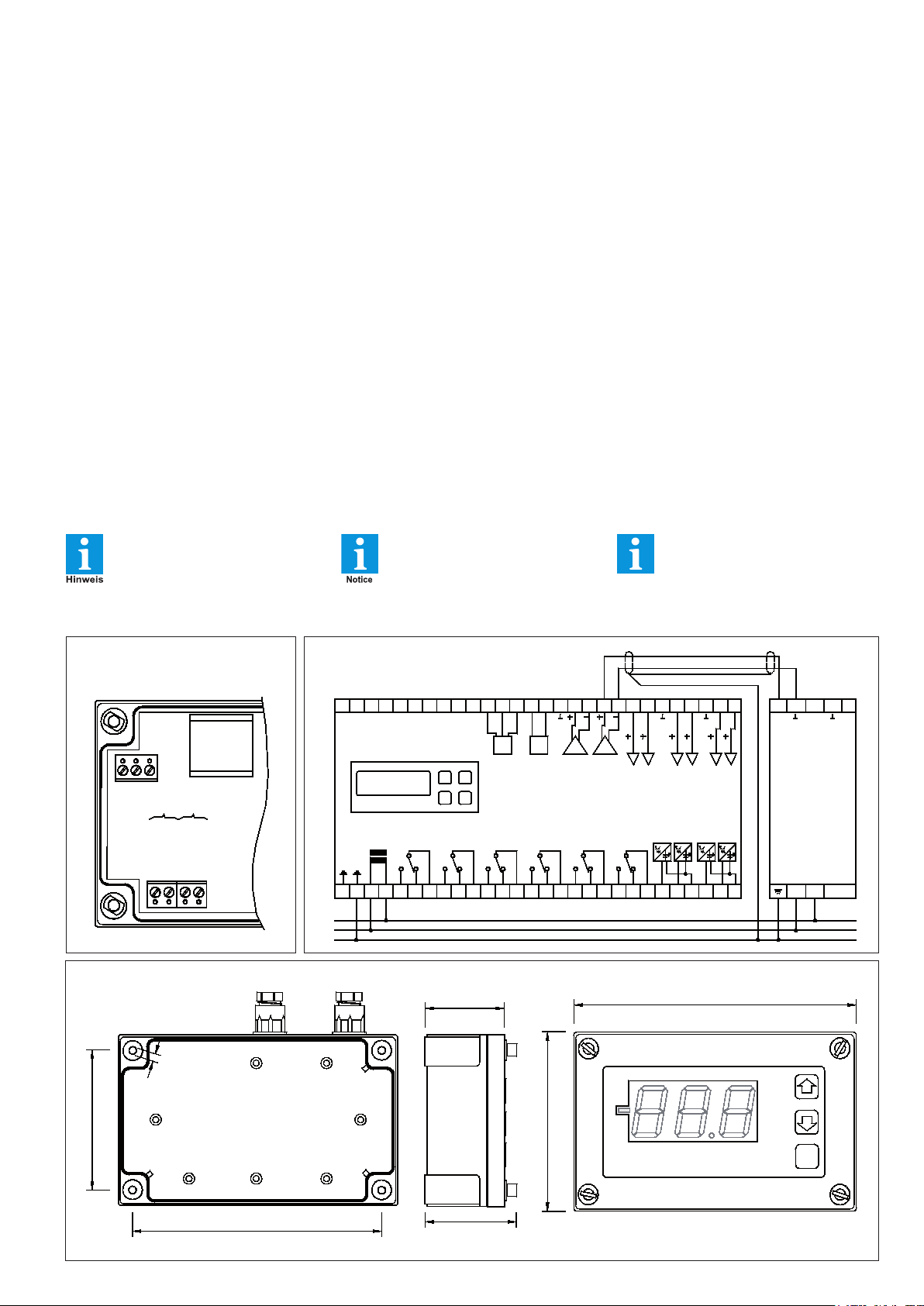
Elektrischer Anschluss
Electrical Connection
Connexions électriques
L 3
N 2
PE 1
4: + 4...20mA
Abmessungen / Dimensions
5: GND
6: + 0...10V
7: GND
Gehäuse-Unterteil
Housing Base Part
Vue arrière boîtier
Anschluss an einem TKP-Kühlstellenregler
Connection to a TKP Cold Storage Controller
Connexions avec le régulateur type TKP
6 7
TAA 2140
TAA 22140
1 2 3
Page 4
Page 4 TAA 2140, TAA 22140
ANSCHLUSS-/SICHERHEITSHINWEISE
Diese Anleitung muss dem Nut
zer jederzeit zugänglich sein. Bei
Schäden, die durch unsachgemäße
Handhabung oder Nichtbeachten der
Anleitung und der Sicherheitshinweise
verursacht werden, übernehmen wir
keine Haftung! In solchen Fällen erlischt jeglicher Garantieanspruch.
Falls Sie Beschädigungen feststellen,
so darf das Produkt
NICHT an Netzspannung angeschlossen werden! Es
besteht Lebensgefahr!
Ein sicherer Betrieb ist eventuell nicht
mehr möglich:
• bei sichtbaren Beschädigungen
• wenn das Gerät nicht funktioniert,
• nach längerer Lagerung unter
ungünstigen Bedingungen,
• bei starken Verschmutzungen oder
Feuchtigkeit,
• nach schweren Transport-
beanspruchungen.
• Die Installation und Inbetrieb-
nahme des Gerätes darf nur
durch eine Elektrofachkraft oder
unter der Aufsicht einer Elektro fachkraft durchgeführt werden.
• Halten Sie das Gerät bei der
Montage sicher vom Stromnetz
getrennt! Stromschlaggefahr!
• Betreiben Sie das Gerät niemals
ohne Gehäuse.
Stromschlaggefahr!
• Eine vorhandene PE-Klemme
des Gerätes muss auf PE gelegt
werden! Stromschlaggefahr!
Zusätzlich funktioniert die interne
Filterung von Störungen nur einge schränkt, fehlerhafte Anzeigen kön nen die Folge sein.
• Das Gerät darf nur für den auf
Seite 1 beschriebenen Einsatz zweck verwendet werden.
• Bitte beachten Sie die am Einsatz ort vorgeschriebenen Sicherheits vorschriften und Normen.
• Bitte prüfen sie vor dem Einsatz des
Reglers dessen technische Grenzen
(siehe Technische Daten), z.B.:
- Spannungsversorgung (auf dem
Gerät aufgedruckt)
- Vorgeschriebene Umgebungs bedingungen (Temperatur- bzw.
Feuchtegrenzen)
Bei Nichtbeachtung sind Fehl funktionen oder Beschädigungen
möglich.
• Signalleitungen müssen abge schirmt sein und dürfen nicht paral lel zu netzführenden Leitungen ver legt werden. Die Abschirmung ist
einseitig, möglichst nahe am Reg ler, zu erden. Wenn nicht, sind
induktive Störungen möglich!
• Bei Verlängerung von Signalkabeln
beachten: Der Querschnitt ist unkri tisch, sollte aber mind. 0,5mm²
betragen. Zu dünne Kabel können
Fehlanzeigen verursachen.
• Vermeiden Sie den Einbau in unmit telbarer Nähe von großen Schützen
(starke Störeinstrahlung möglich).
CONNECTION/SAFETY INSTRUCTIONS
-
The guarantee will lapse in case of da
mage caused by failure to comply with
these operating instructions! We shall
Notice
not be liable for any consequent loss!
We do not accept liability for personal
injury or damage to property caused
by inadequate handling or non-observance of the safety instructions! The
guarantee will lapse in such cases.
If you notice any damage, the product
may
not be connected to mains volta-
ge! Danger of Life!
DANGER
A riskless operation is impossible if:
• The device has visible damages or
doesn't work
• After a long-time storage under
unfavourable conditions
• The device is strongly draggled/wet
• After inadequate shipping conditions
• Never use this product in equip ment or systems that are intended
to be used under such circum stances that may affect human life.
For applications requiring extremely
high reliability, please contact the
manufacturer first.
• The product may only be used
for the applications described on
page 1.
• Electrical installation and putting
into service must be done from
qualified personnel.
• During installation and wiring
never work when the electricity is
not cut-off ! Danger of electric
shock!
• Never operate unit without
housing. Dangerofelectric shock!
• All ‘PE’ terminals must be
connected to ground.
Danger of electric shock!
Additionally, the internal noise
filter will not work, faulty indicated
values may occur.
• Please note the safety instructions
and standards of your place of
installation!
• Before installation: Check the limits
of the controller and the application
(see tech. data). Check amongst
CAUTION
others:
- Supply voltage
- Environmental limits for
temperature/humidity.
Outside these limits malfunction or
damages may occur.
• Measuring cables must be shielded.
Don’t install them in parallel
to high-current cables.
Shielding must be connected to PE
at the end close to the controller.
If not, inductive interferences may
occur.
• Please note for elongation: The wire
gauge is not critical, but should have
0,5mm² as a minimum.
• Mounting the product close to
power relays is unfavourable. Strong
electro-magnetic interference,
malfunction may occur!
CONSIGNES DE SECURITE ELECTRIQUES
-
L'utilisateur doit toujours être en pos
session de cette notice. En cas de
dommage dû à l'inobservation de la
Notice
présente notice, la garantie est nulle.
Si vous constatez une quelconque
anomalie, l'appareil ne doit pas
DANGER
être mis sous tension ! Risque
d'électrocution ! Le fonctionnement
n'est plus sûre si :
• l'appareil est détérioré
extérieurement,
• l'appareil ne fonctionne plus,
• l'appareil était stocké un long
moment dans
de mauvaises conditions,
• l'appareil est très sale ou humide
• l'appareil a été endommagé durant
le transport.
• L'installation et la mise en route
de l'appareil doivent s'effectuer par
ou en présence d'un spécialiste.
• Vérifier lors du montage que
l'appareil est bien hors tension !
Risque d'électrocution !
• Ne jamais utiliser l'appareil sans
son boîtier de protection.
Risque d'électrocution !
• La borne de terre disponible sur
l'appareil doit être reliée à la terre
! Risque d'électrocution ! Si la terre
n'est pas correctement branchée,
le filtrage interne ne fonctionne pas
et peut entrainer des variations
sur l'afficheur.
• L'appareil convient uniquement
aux applications indiquées à la
page 1 de cette notice.
• Respecter les consignes générales
de sécurité du pays où l'appareil
est installé.
• Vérifier les conditions de fonction nement de l'appareil :
- Tension d'alimentation
ATTENTION
- Ambiance
(Température et humidité)
Possibillité de panne ou endom
magement si les intensités ne sont
pas respectées.
• Les câbles de sonde doivent être
blindés et séparés des câbles de
puissance. Le blindage doit être
relié d'un côté à la terre, au plus
prêt du régulateur, afin d'éviter les
problèmes d'induction!
• La section des câbles d'extension
de sonde doit être d'au moins
0,5mm². Des câbles trop fins peu vent entraînés des défauts
d'affichage.
• Eviter de placer le produit à
proximité de contacteurs de forte
puissance.
-
-
 Loading...