

Page 1
Brief Description / Applications
• Controller for all kind of Storages, such as Walk-In Coolers/Freezers,
Refrigerated Shelfs, Refrigerated Counters, Refrigerated Cases, etc.
• For standard cold storages or cold storages with pulse-width modulated
expansion valves, expansion valves with thermal drive and stepper
motor valves (with addtional EVS module)
• For single or network operation
• 5 Temperature sensors, 5 Relays, 4 Digital Inputs, Analogue In-/Output
Please note safety instructions !
DANGER
This is a brief version of the technical manual.
A complete version you can find on www.elreha.de,
our free INFO-CD and via Handy Apps.
ELEKTRONISCHE REGELUNGEN GMBH
Short Manual 5321437-00/00e/00
Cold Storage
Controller
Type:
EVP 3167
2018-06-25, tkd/jr
CONNECTION INFORMATION & SAFETY INSTRUCTIONS
The guarantee will lapse in case of damage caused by failure
to comply with these operating instructions! We shall not be
liable for any consequent loss! We do not accept liability for
Notice
personal injury or damage to property caused by inadequate
handling or non-observance of the safety instructions! The
guarantee will lapse in such cases.
This manual contains additional safety instructions in the
functional description. Please note them!
If you notice any damage, the product may
not be connected
to mains voltage! Danger of Life!
A riskless operation is impossible if:
Danger
• The device has visible damages or doesn't work
• After a long-time storage under unfavourable conditions
• The device is strongly draggled or wet
• After inadequate shipping conditions
• Never use this product in equipment or systems that are
intended to be used under such circumstances that may
affect human life. For applications requiring extremely
high reliability, please contact the manufacturer first.
• The product may only be used for the applications
described above.
• Electrical installation and putting into service must be
done from qualified personnel.
• During installation and wiring never work when the
electricity is not cut-off ! Danger of electric shock!
•
To prevent electrical shock, the device may only be
operated in a closed control cabinet or control box.
• Never operate unit without housing.
Danger of electric shock!
• All ‘PE’ terminals must be connected to PE.
Danger of electric shock! Additionally, the internal noise
filter will not work, faulty indicated values may occur.
• Please note the safety instructions and standards of your
place of installation!
• Before installation: Check the limits of the controller and
the application (see tech. data). Check amongst others:
- Make sure that all wiring has been made in accordance
with the wiring diagram in this manual.
- Supply voltage (is printed on the type label).
- Environmental limits for temperature/humidity.
- Maximum admitted current rate for the relays. Compare
it with the peak start-up currents of the controlled loads
(motors, heaters,etc.).
Outside these limits malfunction or damages may occur.
• Sensor/probe cables must be shielded. Don’t install them
in parallel to high-current cables. Shielding must be
connected to PE at the end close to the controller.
If not, inductive interferences may occur.
• Please note for elongation: The wire gauge is not critical,
but should have 0,5mm² as a minimum.
• Mounting the controller close to power relays is
unfavourable. Strong electro-magnetic interference,
malfunction may occur!
• Take care that the wiring of interface lines meets the
necessary requirements.
• TF-type sensors are not designed for being immersed in
fluids permanently. In such a case, always use dip-fittings.
With extreme temperature variations, the sensor may be
damaged.
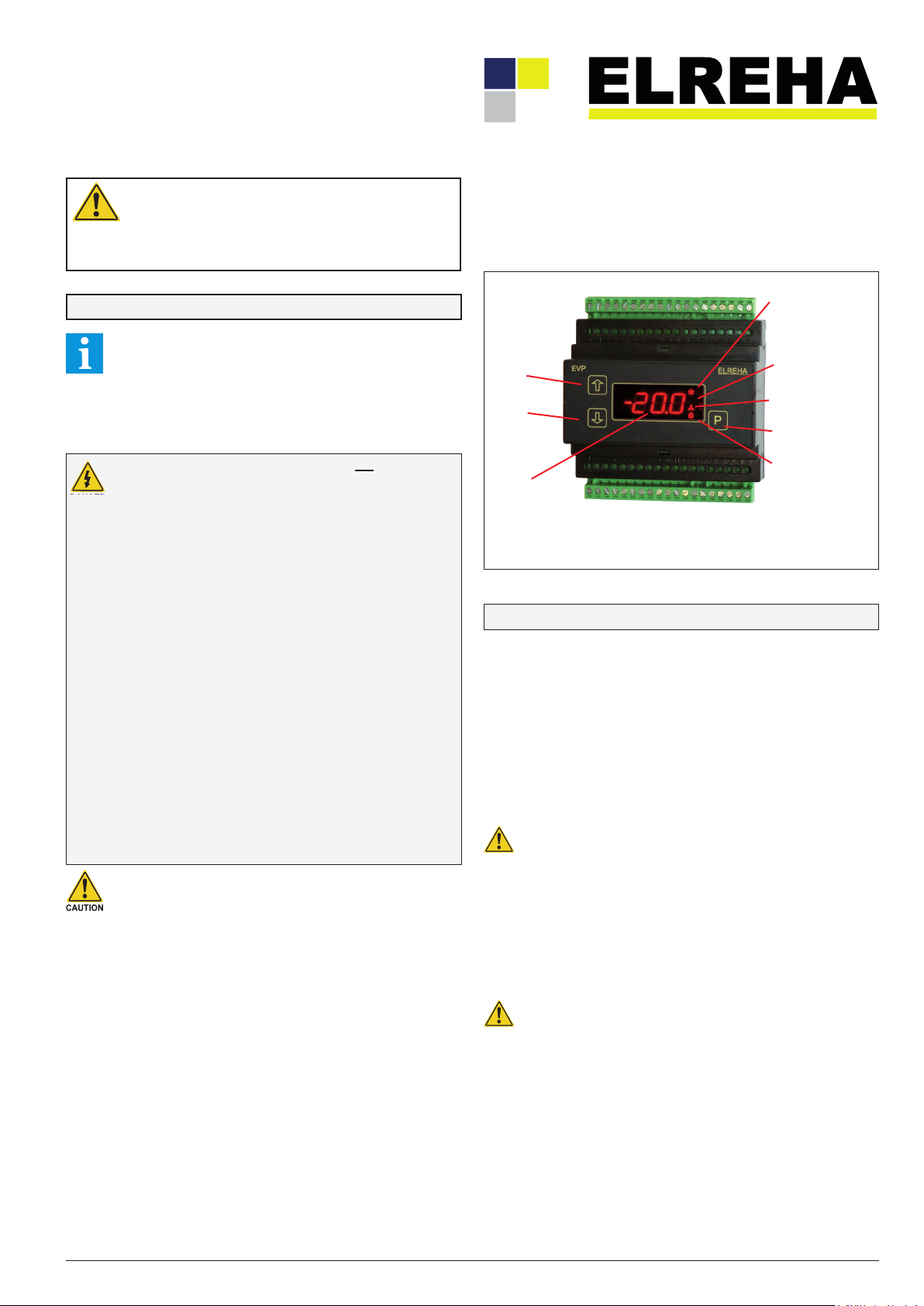
LED on = cooling
LED blinking
= Min. idle time or
= Cooling delay after
mains failure
= Cool. pause after defr.
increase
values
decrease
values
The currently displayed
setpoint is active
3 keys allow programming the unit, all parameters will be displayed on
the red LED-7-segment display. 4 red symbols at the right side indicate
specific control functions (not the relay states, these are displayed on the
'Actual Page' !).
LED on = defrost
LED blinking
= Pause before defrost
LED on = fan is running
LED blinking
= Start delay
Programming key
LED blinking = alarm
Technical Data
Supply Voltage .............................230V, 50-60Hz, max. 9VA (controller only)
Ambient Temperature .......................................................................
Max. Ambient Humidity ...........................................85% r.F., not condensing
Analogue Inputs ........................... 5x Temperature Sensors TF 201 (PTC)
or TF 501 (Pt 1000), as well as customer specific probes
1x pressure transducer 0(2)-10V (scalable), Ri=69 kOhm
Measuring ranges ...................TF 501
of the probe inputs TF 201
So1 ......................................... -40°C...+25°C
So2 .........................................
TF 202
The temperature ranges of the probe heads
and cables must be observed !
Accuracy .....................................................±0.5K in range -35...25°C within
the ambient temperature range 10...30°C
Digital Inputs ......................................................4x mains voltage, 3mA max.
overvoltage category II, pollution degree 2
Relay Outputs .......................1x SPDT, 3x SPST, isolated, 8A res/3A ind./250V
overvoltage category III, pollution degree 2
SSR-Output (e.g. for EEx-Valve) ...................... 1x Solid-State-Relay (SSR),
max. 0,5 A / 250VAC
overvoltage category III, pollution degree 2
Please note the information at the connection plan about a
necessary snubber circuit at the SSR output!
Transducer Supply .............................................22V DC ±10%, 40 mA max.
Analogue Output ...........................................0...10V or 4...20mA (selectable)
0...10VDC, max. current typ. 1mA
4...20 mA, max. shunt resistance 250 ohms
Display/Parameter Ranges ..........................................see parameter pages
Data Interfaces ...............................................................................3x RS 485
Data storage ......................................................................................
Real Time Clock ..........................................automatic summer/winter switch
10 days clock backup without mains voltage
Housing ................ plastic with foil keypad for rail mounting (DIN EN 50022),
screw terminals 2,5 mm
(Pt1000) ....................-100°C...+100°C
(PTC, 2 kΩ at°C) ........... -50°C...+100°C
(PTC, 990 Ω at 25°C) .....-55°C...+100°C
0...+50°C
-50°C...+50°C
unlimited
Page 2
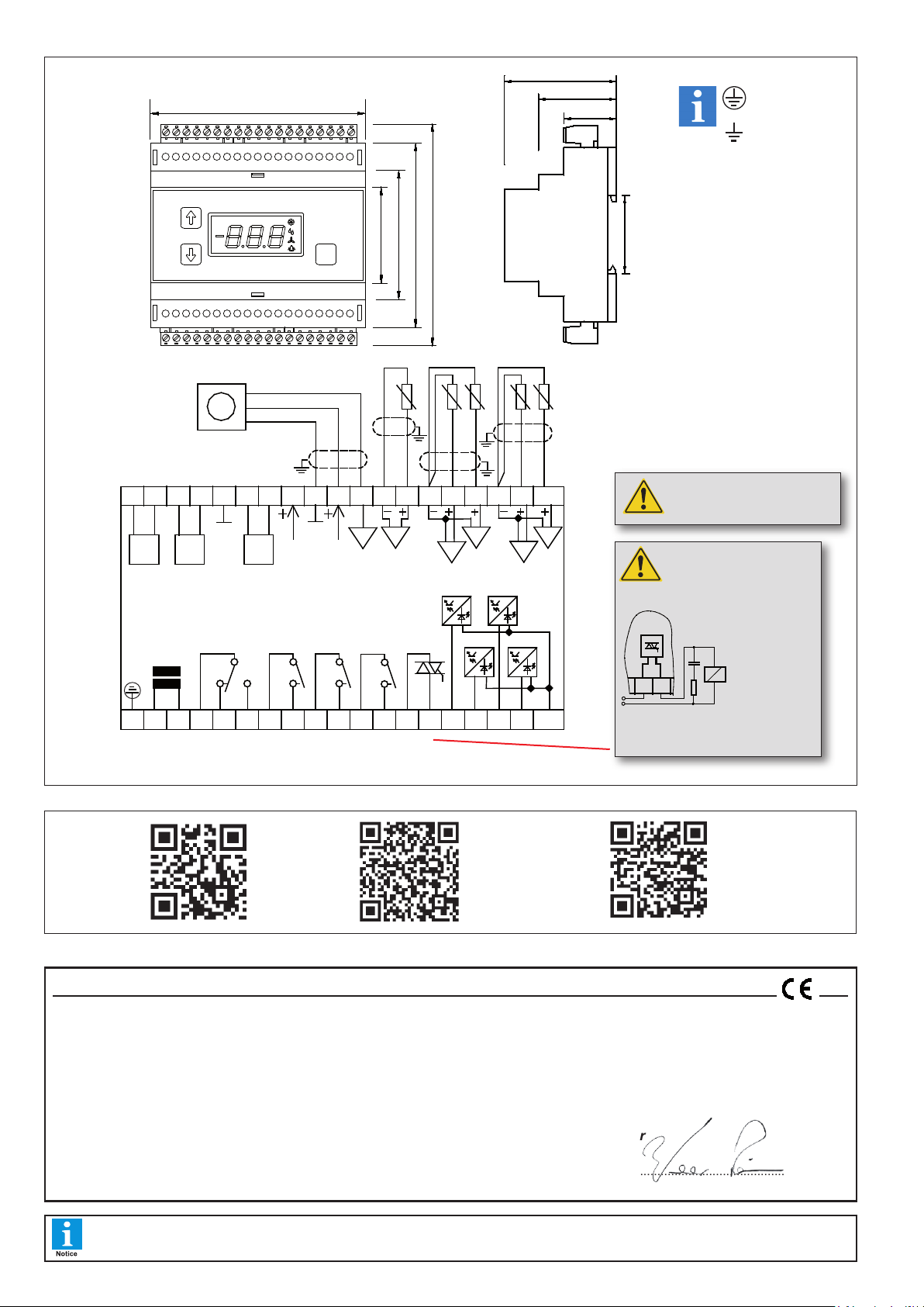
Dimensions & Wiring
35(1.38)
26 (1 .02 )
59 (2 .32 )
39 (1 .54 )
1 2 3
4
1 2 83 4 5 76 12119 1310
22
EVP
20 21 2723 24 25 26 28 3229 3130
105 (4 .13 )
46 (1.81)
63 (2.48)
91 (3.58)
115 (4.53)
1915 1814 16 17
ELR EHA
P
3837343 3 35 3 6
SSR Rel ay
RC- Glied
RC- circuit
12
31
relay
K1
N
1 2 3L4 5
EVP 3167
relayK2relayK3relay
K4
6 7 8 9 10 11
242120 2322 2825 26 27 29 30
19
relay
(SS R)
K5
DI 2
DI 4
1613 14 15 17 18
L
N
DI 1 DI 3
383532 33 34 36 37
L
L
L
RS
485
NDO
DO
RS
485
NDO
DO
RS
485
NDO
DO
PT
For the device EVP 3167 we state the following: When operated in accordance with the technical manual, the criteria have been met that are outlined in the
EMC Directive 2014/30/EC and the Low Voltage Directive 2014/35/EC.
This declaration is valid for those products covered by the technical manual which itself is part of the declaration.
Following standards were consulted for the conformity testing to meet the requirements of EMC and Low Voltage Guidelines:
E
N 55011:2016+A1:2017, EN 61010-1:2010, EN 61326-1:2013
CE marking of year: 2018
This statement is made for the manufacturer / importer by:
ELREHA Elektronische Regelungen GmbH Werner Roemer, Technical Director
D-68766 Hockenheim
www.elreha.de Hockenheim.............2018-06-22.......................................................
(Name / Address) C
ity Date Signature
EC Declaration of Conformity
Short Manual Cold Storage Controller EVP 3167Page 2
Protective Earth
PE
Remote
Displays
{
mains
Slave
{
Modules
Signal (signal out) 2-10V
+ Versorgung (supply)
Masse (ground)
Network
(Line)
{
analog out
22V supply
Note
Earth
Dimensions in mm,
(in brackets = inches)
When connecting the switch
outputs, the overvoltage
category must be respected !
Analog
IN
sensor 5
sensor 4
sensor 2
sensor 3
sensor 1
* With connecting an
inductive load to the SSR
output, like e.g. a relay, it may
be necessary to connect a snubber
circuit in parallel to the load
to protect the
output from an
uncontrolled
turn on. By an
uncontrolled
turn on it is
possible that the
load is switched
on permanently. The snubber circuit
*
must be adapted to the load.
Complete
operating
instructions
you can find
over these
www.elreha.de
IOS APP Store
ELREHA
Manual APP
Google Play Store
ELREHA
Manual APP
ways
This manual, which is part of the product, has been set up with care and our best knowledge, but mistakes are still possible. Technical details can be changed
without notice, especially the software. Please note that the described functions are only valid for units containing the software with the version-number shown
on page 1 of this manual. Units with an other version number may work a little bit different.
 Loading...