

Page 1
In controllers which contain older software
versions, some functions may not be available!
Brief Description / Applications
• Controller for all kind of Storages, such as Walk-In Coolers/Freezers,
Refrigerated Shelfs, Refrigerated Counters, Refrigerated Cases, etc.
• For standard cold storages or cold storages with pulse-width modulated
expansion valves or expansion valves with thermal drive
• For single or network operation
• 4 Temperature sensors, 4 Relays, 2 Digital Inputs, Analogue In-/Output
Standard Functions
• Controls temperature, defrost device, evaporator fans, roller blinds, etc.
• Up to 3 evaporators with a single device
• 2 expansion Valve control methods selectable
• Valve control is fully autoadaptive
• Foresight control and condenser pressure optimization in cooperation
with the VPR compressor compounds central unit
• Intelligent defrost control, able to learn, no additional sensors
• Defrost Start fully automatic, by 6 release times or manually
• Defrost cycle is pulsed, controlled by evap sensor (variable intervals)
• Automatic recognition of the leading evaporator
• Emergency Mode if sensor or defrost recognition fails.
Autoreset after repair
• Use of Latency Heat by intelligent fan control
This may be a brief version of the technical manual.
A complete version with the pages 7...16 you can
find on www.elreha.de or our free INFO-CD.
Programming
All parameters of the EVP are distributed on different pages.
While normal operation or if no key is pressed for about 3 minutes, the EVP
displays the following information:
1st priority: current failure (blinking)
2nd priority: operating states (e.g. 'oFF')
3rd priority: selected 'permanent parameter' display
Selecting and Changing of Parameters
key action
P (> 2 sec.) .......Page name will be displayed
...................Select desired page
P .....................Enter the page
...................Select parameter
P .....................Prepare programming. Enter access code if necessary
...................Change value.
If you hold the key, the values change faster and faster
P .....................Confirm programming
P (> 2 sec.) .......Page name will be displayed again
If an older version must be replaced
- please note the modified terminals!
Technical Manual 5311092-00/26E
Cold Storage Controller
from SoftVers. 1.61
Types:
EVP 3150-1
EVP 3150-2
ELE KTR ONI SCH E R EGE LUN GEN G MBH
Please note safety instructions !
Parameter Pages
P
(L)
> 2 sec.
Actual
Values
Page
P
(r)
Setpoint
Page
(d)
Defrost
Page
(P)
Mode
Page
(h)
Assignment
Page
L01
r01
d01
P01
h01
1st. Parameter on the:
P
P
P
P
Access Protection
Except the temperature setpoints, parameters can be changed only after
entering a correct access code. If you want to change such a parameter after
pushing the "P"-key, then the following display appears:
Now the controller expects the entry of a code number .
This code number is always 88. Enter it by the up/down keys
and confirm it by pressing "P" again.
If no key is pushed for about 3 minutes, the code number must be entered
again.
88
(00
Manual Defrost
Start manual defrost: - Select "
d50" (Defrost Page),
- Set it to "on" and confirm.
Stop manual defrost: - Select "d50" (Defrost Page),
- Set it to "oFF" and confirm.
CAUTION
DANGER
Notice
Operating / Operating Elements
increase
values
decrease
values
The currently displayed
setpoint is active
1 2 3
4
EVP
ELR EHA
P
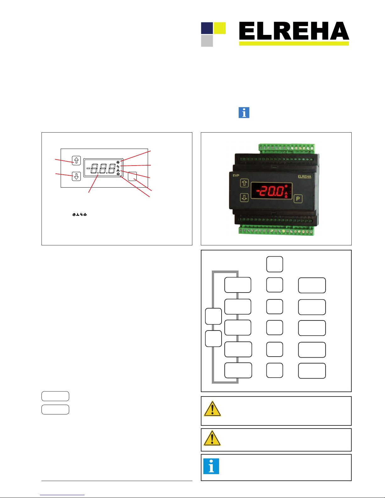
3 keys allow programming the unit, all parameters will be displayed on
the red LED-7-segment display. 4 red symbols at the right side indicate
specific control functions (not the relay states, these are displayed on the
'Actual Page' !).
LED on = cooling
LED on = fan is running
Programming key
LED blinking = alarm
LEDs are blinking the same time =
control functions are disabled by digital input or via interface
LED on = defrost
The current states of the digital inputs can be read under L60, the state of the
relays and the data transmission can be read under L61 (Actual Values Page).
EV P
P
EL RE H A
The front view of the version with an older display you will find on page 6.
Page 2
Technical Manual Cold Storage Controller EVP 3150-1 and EVP 3150-2Page 2
For the device EVP 3150-2 we state the following: When operated in accordance
with the technical manual, the criteria have been met that are outlined in the
EMC Directive 2014/30/EC and the Low Voltage Directive 2014/35/EC.
This declaration is valid for those products covered by the technical manual
which itself is part of the declaration.
Following standards were consulted for the conformity testing to meet the
requirements of EMC and Low Voltage Guidelines:
EN
55011:2016
EN 61010-1:2010
EN 61326-1:2013
CE marking of year: 2017
This statement is made from the manufacturer / importer by:
ELREHA, Elektronische Regelungen GmbH
D-68766 Hockenheim
by
Werner Roemer, Technical Director
(Name)
Hockenheim.............26.6.2017......................................................................
(City) (Date) (Signature)
EC Declaration of Conformity
Accessories
- Temperature sensor TF 501, quantity depends on application
- Pressure Transducer DG 0/10 2/10V with 2-10VDC output
- PC-Software "COOLVision"
Module "COOLVision-MES" for remote control and configuration
Modules "COOLVision-Analyse" and "COOLVision-SMM"
for data logging, visualization and alarm forwarding.
Technical Data
Supply Voltage EVP 3150-x ............................. 230V, 50-60Hz, max. 9VA
EVP 23150-x ................................
115V, 60 Hz, max. 9VA
max. 240VA with full load of the SSR-output
Ambient Temperature .......................................................................0...+50°C
Max. Ambient Humidity ...........................................85% r.F., not condensing
Analogue Inputs ...................................................
4x Temperature Sensors
TF 201 (PTC) or TF 501 (Pt 1000)
1x pressure transducer 0(2)-10V (scalable), Ri=69 kOhm
Measuring ranges ...................TF 501 (Pt1000) .................... -100°C...+100°C
of the probe inputs TF 201
(PTC, 2 kΩ at°C) ........... -50°C...+100°C
So1 .........................................
-40°C...+25°C
So2 .........................................
-50°C...+50°C
The temperature ranges of the probe heads
and cables must be obeserved !
Accuracy .....................................................±0.5K in range -35...25°C within
the ambient temperature range 10...30°C
Digital Inputs ......................................................2x mains voltage, 3mA max.
Relay Outputs ........................................ 3x SPDT isolated, 8A res/3A ind./250V
EEx-Valve Output ..............
1x Solid-State-Relay (SSR), max. 1A / 250VAC
or 230V DC / 500mA
Please note the information at the connection plan about a
necessary snubber circuit at the SSR output!
Transducer Supply .............................................22V DC ±10%, 40 mA max.
Analogue Output ...........................................0...10V or 4...20mA (selectable)
0...10VDC, max. current typ. 1mA
4...20 mA, max. shunt resistance 250 ohms
Display/Parameter Ranges ..........................................see parameter pages
Data Interface ......................................................................................RS 485
Data storage ......................................................................................unlimited
Real Time Clock ..........................................automatic summer/winter switch
10 days clock backup without mains voltage
Housing ................ plastic with foil keypad for rail mounting (DIN EN 50022),
screw terminals 2,5 mm
Danger
Notice
CONNECTION INFORMATION & SAFETY INSTRUCTIONS
The guarantee will lapse in case of damage caused by failure
to comply with these operating instructions! We shall not be
liable for any consequent loss! We do not accept liability for
personal injury or damage to property caused by inadequate
handling or non-observance of the safety instructions! The
guarantee will lapse in such cases.
This manual contains additional safety instructions in the
functional description. Please note them!
If you notice any damage, the product may not be connected
to mains voltage! Danger of Life!
A riskless operation is impossible if:
• The device has visible damages or doesn't work
• After a long-time storage under unfavourable conditions
• The device is strongly draggled or wet
• After inadequate shipping conditions
• Never use this product in equipment or systems that are
intended to be used under such circumstances that may
affect human life. For applications requiring extremely
high reliability, please contact the manufacturer first.
• The product may only be used for the applications
described on page 1.
• Electrical installation and putting into service must be
done from qualified personnel.
• During installation and wiring never work when the
electricity is not cut-off ! Danger of electric shock!
• To prevent electrical shock, the device may only be
operated in a closed control cabinet or control box.
• Never operate unit without housing.
Danger of electric shock!
• All ‘PE’ terminals must be connected to PE.
Danger of electric shock! Additionally, the internal noise
filter will not work, faulty indicated values may occur.
• Please note the safety instructions and standards of your
place of installation!
• Before installation: Check the limits of the controller and
the application (see tech. data). Check amongst others:
- Make sure that all wiring has been made in accordance
with the wiring diagram in this manual.
- Supply voltage (is printed on the type label).
- Environmental limits for temperature/humidity.
- Maximum admitted current rate for the relays. Compare
it with the peak start-up currents of the controlled loads
(motors, heaters,etc.).
Outside these limits malfunction or damages may occur.
• Sensor/probe cables must be shielded. Don’t install them
in parallel to high-current cables. Shielding must be
connected to PE at the end close to the controller.
If not, inductive interferences may occur.
• Please note for elongation: The wire gauge is not critical,
but should have 0,5mm² as a minimum.
• Mounting the controller close to power relays is
unfavourable. Strong electro-magnetic interference,
malfunction may occur!
• Take care that the wiring of interface lines meets the
necessary requirements.
• All used temperature sensors must be identical. Never
use different types at the same time. This will not work.
• TF-type sensors are not designed for being immersed in
fluids permanently. In such a case, always use dip-fittings.
With extreme temperature variations, the sensor may be
damaged.
Cleaning
The use of a dry, lint-free cloth and household agents is
sufficient to clean the product.
Never use acids or acidic fluids! Risk of damage!
Page 3
Technical Manual Cold Storage Controller EVP 3150-1 and EVP 3150-2 Page 3
Error Messages / Error Memory / Error Codes
If a failure occurs, the controller will show parameter P43 with an error code with a flashing display automatically. Always the last 15 errot messages keep memorized with date and time of their appearance
and can be read-out via data interface.
---- .............. no error
sel ............ error in assignment page, e.g. function selected too often
Thi ............ alarm sensor, overtemperature
tlo ............ alarm sensor, undertemperature
tXb ............ sensor X broken
tXc ............ sensor X hot-wired
dbt ............ number of defrost cycles without termination by temperature exceeded,
maybe too many ice or heater malfunction.
rrt ............ cooling has achieved maximum runtime. This message is only active at point-in-time
set by
P42 (mode page).
rdo ............ door contact is open too long. This message is only active at point-in-time set
by
P42 (mode page).
dor ............ door X is open
opc ............ alarm at digital input X
cha ............ safety chain open
hrd ............ hardware failure
If a sensor is short or broken, a time delay of 5 seconds takes effect before an alarm will be activated.
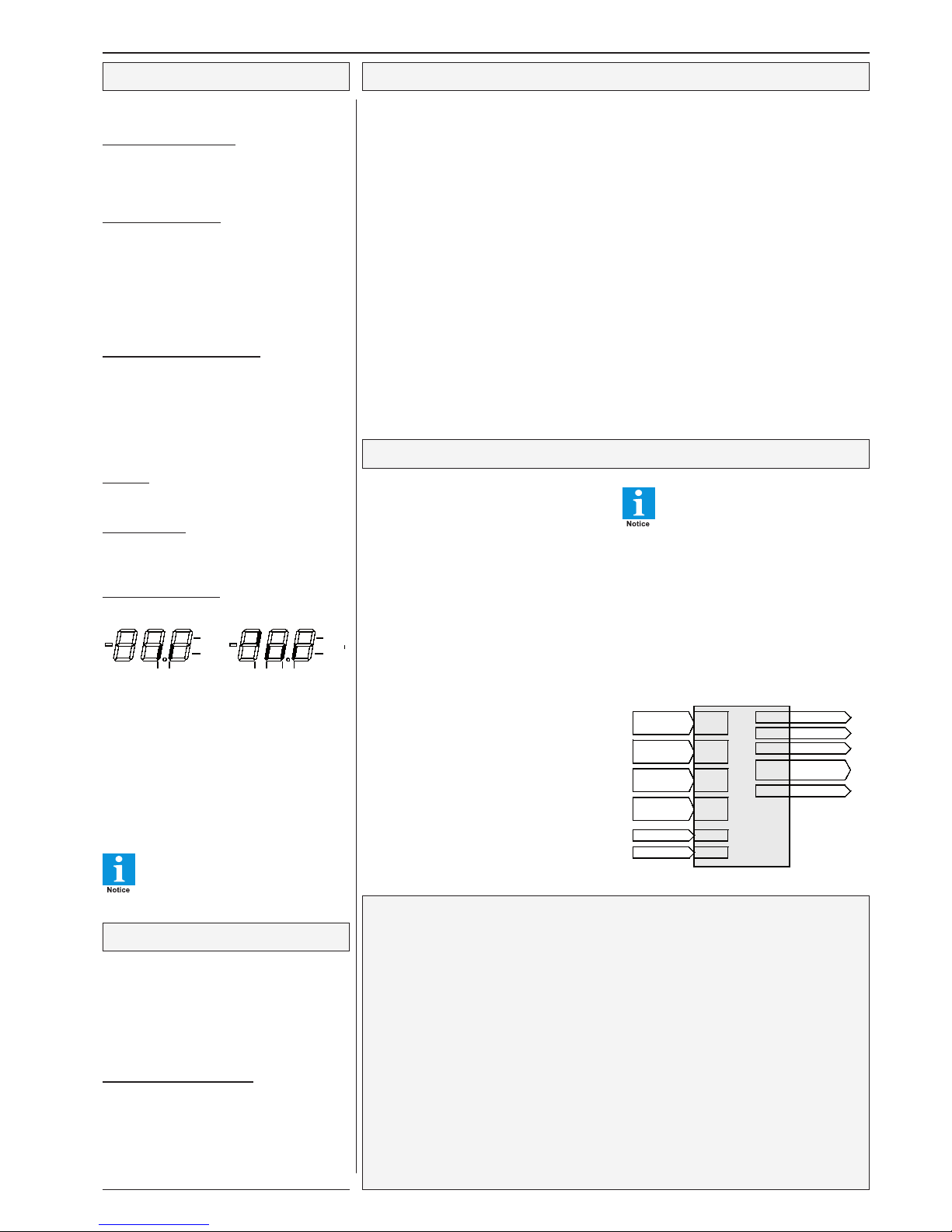
Configuration Concept
The inputs/outputs of the EVP-cold storage controller
have no fixed tasks. The EVP works with a "free
configurable" concept, this means that all available
inputs and outputs (relays, sensors, digital inputs,
analogue output) can be configured to work with any
integrated control function or control circuit.
Sensors
Each sensor can fulfill each function, even up to 3
functions at the same time. (Function (a) of sensor
X, Function (b) of sensor X, Function (c) of sensor
X, X = sensor#). e.g.:
1. Control sensor /alarm sensor at the same time
2. Defrost limitation sensor and control sensor at
the same time, e.g. to control a refrigerated
shelf by the temperature of its air outlet.
Virtual Sensors
Up to 4 sensors can be combined to a 'virtual' sensor
to realize averaging with selectable emphasis.
Digital inputs (Optocoupler inputs)
Each digital input can be assigned to one of the
possible functions.
Relay Outputs
Each relay can be used to control one of the possible
functions. The same function can even be assigned
to multiple relays.
Relay output #4 is a Solid State Relay
with a lower contact rating than the
standard relay outputs. Normally, this
output is used for driving Electronic Ex-
pansion Valves, but can be used for any
other task if it works within the specified current
range.
Parameter
Parameters of functions which are not assigned will not
appear in the parameter pages to improve survey.
Assignment
The function of each input and output can be preset
on the 'assignment page'. The assignment can be
done by keys or via interface.
Configuration Example for an EEx-Valve
Configuration of the controller
Hereby we use the example from above: A cold storage with an evaporator with Electronic Expansion
Valve.
Action Key Display Remarks
enter page lising ..........................."P" .......(A) ...............hold key for > 2 seconds
select assignment page................"" .... (h)
enter asssignment page ..............."P" .......h01 ..............h01 is the 1st parameter on the page and
determines the function of relay 1
displaying the function of relay 1 .."P" .......any
new assignment of relay 1 ..........."P" ....... C00 ............(Code expected) only if no key key is hit for
about 3 minutes
enter access code ........................"" .......C88
confirm .........................................."P" ....... any
select function ..............................."" .... ALA .............ALA = alarm relay
confirm .........................................."P" ....... h01 ..............parameter # will be displayed again
select new in-/output ....................."" .......h02 ..............determines the function of relay 2
displaying the function of relay 2 .."P" .......any
new assignment of relay 2 ..........."P" ....... any
select function ..............................."" .... dF1 .............dF 1= defrost relay (evaporator 1)
confirm .........................................."P" ....... h02 ..............parameter # will be displayed again
Repeat this steps until all inputs and outputs are assigned to the desired functions.
Display of actual values and states
All actual values are shown on the "Actual Values
Page" ((l)).
Status of the controller unit
If the 4 status LED's on the front are blinking
simultaneously and the display shows "oFF", the
control functions are disabled by digital input or
data interface.
Display of temperatures
"L01" -" L04" (Actual Values Page) show the actual
temperature value of the sensors 1-4 in a range
within -100... +100°C. "L05" shows a temperature
value which is calculated from the pressure value
of the transducer and the selected refrigerant table,
"L07" shows the 'virtual' temperature value.
With "P31"-"P34" and "P36" (Mode Page) this
displays can be calibrated.
Expansion Valve Status Display
This shows the current, average aperture size
from 0...100 % and additionally the actual state
of the valve.
cut = Restart of the evaporator after abnormal
operating conditions (cutoff)
pdo = Pumpdown of the refrigerant
(cooling relay ON for 30 sec.)
Setpoints
The active day or night setpoints are indicated by
the left decimal point switched on.
Time information
The Actual Values Page contains all runtime- /
remaining time information, so the times up to the
start of a function can be read.
Status of inputs/outputs
Digital-(OK)-Inputs State of the relays
Analogue Output: Parameter L50, value in %
Temperature Sensors
These types of temperature sensors can be used:
- TF 201, PTC sensor (2000 ohms@25°C)
- TF 501, PT1000 sensor (1000 ohms@0°C)
- customer specific sensor So1 (-40...+25°C)
- customer specific sensor So2 (-50...+50°C)
The type of sensor can be set by 'P35' (Mode
Page).
Please don't use the TF 201 sensor
if you work with Electronic
Expansion Valves.
'Permanent Parameter' - Function
After power-up of the controller, the display will
indicate the 'permanent parameter' after some
seconds (or in case of a failure it will display the
current failure). This can also be read if you don’t
touch a key for more than 3 minutes.
If you think that it is suggestive to show any sensor
value as permanent parameter, do the following:
Change permanent parameter
- Select the parameter you want to have as
'permanent parameter'
- Press "
" and " " simultaneously.
The display shows "
888" for a moment, after
that the selected parameter will be shown as
the 'permanent parameter'.
OK 21
23 0V
0V
Relay
On
OFF
1: con
2: ALA
3:........................
1: dF1
2: .......................
3:........................
1: out
2: .......................
3:........................
1: InL
2: .......................
3:........................
dEF
dnh
sensor 1
sensor 2
sensor 3
sensor 4
relay 1
relay 2
relay 3
SolidState
Relay 4
Analog
EVP
Assignment
In-/Outputs
ALA
dF1
FAn
EEP
dIS
DI 1
DI 2
Page 4

Technical Manual Cold Storage Controller EVP 3150-1 and EVP 3150-2Page 4
Parameter Pages
Actual Values Page (L)
Setpoint Page (r)
Defrost Page (d)
Param. Note Range Factory Setting
r01 ..........................Setpoint Layer ..........................................................................................................................1, 2 ............................... 1
r02 ..........................Setpoint 1 (day) ........................................................................................................................-100/+100°C ................ -20°C
r03 ..........................Setpoint 2 (night) ......................................................................................................................-100/+100°C ................ -20°C
r04 ..........................Setpoint 1 (day), Setpoint Layer 2 ...........................................................................................-100/+100°C ................ -20°C
r05 ..........................Setpoint 2 (night), Setpoint Layer 2 .........................................................................................-100/+100°C ................ -20°C
r10 ..........................Hysteresis .................................................................................................................................0,1...20K ...................... 2 K
r22 ..........................Fan start delay ..........................................................................................................................0...30 (min.) ............... 5 min.
r23 ..........................Fan trailing delay ......................................................................................................................0...30 (min.) .............. 0 min.
r31 ..........................Runtime check cooling (in 10 minute steps) ................................... .......................................off, 00.0...23.5 ........... off
r32 ..........................Runtime check door (in 10 minute steps) ................................................................................off, 00.0...23.5 ........... off
r33 ..........................Minimum compressor idle time ................................................................................................0...30 min. ................... 0 min.
r34 ..........................Cooling delay after mains voltage loss ....................................................................................0...30 min. ................... 0 min.
r41 ..........................Alarm offset (relative to the setpoint) .......................................................................................0...100K ...................... 7 K
r42 .............. ............Alarm offset, Layer 2 (relative to the setpoint) .........................................................................0...100K ....................... 7 K
r43 ..........................Lower Alarm Limit (absolute value, threshold for low temperature limitation/alarm) .............-100/+100°C ................ - 50°C
!! Function cannot be switched off.
r44 ..........................Lower Alarm Limit, Layer 2 (absolute value) ...........................................................................-100/+100°C ................ - 50°C
r45 ..........................Temperature Alarm Delay ........................................................................................................0...120 min. ................. 45 min.
r46 ..........................Release time of safety chain ....................................................................................................0...60 sec. .................... 60 sec.
r51 ..........................PID proportional band ..............................................................................................................0.1...30.0 ...................... 4.0
r52 ..........................PID integration time ..................................................................................................................off, 1...600 sec. ......... 10 sec.
r53 ..........................PID attack time .........................................................................................................................off, 1...10 sec. ........... off
r54 ..........................PID delay ..................................................................................................................................off, 0.1...10.0 sec. ...... off
r56 ..........................Actuating Variable Delay of Analogue Output (for PID only) / output delay ...........................0...240 sec. .................. 0 sec.
r57 ..........................Actuating Variable Delay of Analogue Output (for PID only) / step size .................................1...100% ...................... 100%
r58 ..........................Cooling/Heating Relay Time Period ........................................................................................1...240 sec. .................. 1 sec.
r59 ..........................Cooling/Heating Relay ON-Time .............................................................................................1...240 sec. .................. 240 sec.
r61 ..........................Digital inputs alarm delay .........................................................................................................0 bis 120 min. ............. 5 min.
r62 ..........................Digital inputs door contact delay ..............................................................................................1 bis 240 min. ............. 5 min.
r63 ..........................Digital input analog value: Voltage/current at the analog outp. with active digital input ........0.0...100.0 %, ............. 0%
Param. Disp. Note Range Factory Setting
d01 .........................Fan during defrost ....................................................................................................................on, off ........................ off
d02 ..........................Defrost Mode ............................................................................................................................etn = external only, .... int
int = extern+intern
AdA = adaptive
d03 ..........................Fan operation before defrost ..................................................................................................0...15 minutes .............. 3 minutes
d04 ............X ..........Time up to defrost (in 10-minutes steps) .................................................................................168.0 h/min.... .............. 00.0
d05 ..........................Maximum time up to defrost (10-minutes steps) .....................................................................02.0...48.0 h/min .......... 24.0 h
d11 ..........................Defrost release time 1 (in 10-minutes steps) ..........................................................................00.0 - 23.5, off .......... 05.0
d12 ..........................Defrost release time 2 (in 10-minutes steps) ..........................................................................00.0 - 23.5, off .......... off
d13 ..........................Defrost release time 3 (in 10-minutes steps) ..........................................................................00.0 - 23.5, off .......... off
d14 ..........................Defrost release time 4 (in 10-minutes steps) ..........................................................................00.0 - 23.5, off .......... off
d15 ..........................Defrost release time 5 (in 10-minutes steps) ..........................................................................00.0 - 23.5, off .......... off
d16 ..........................Defrost release time 6 (in 10-minutes steps) ..........................................................................00.0 - 23.5, off .......... off
d31 ..........................Defrost limitation temperature .................................................................................................0.0°C...100°C .............. 14.0°C
d32 ..........................Max. defrost runtime (defrost safety time) ...............................................................................0...240 minutes ............ 45 min.
d33 ..........................Alarm time extension after defrost ...........................................................................................0...60 minutes .............. 30 min.
d34 ..........................Pulse-defrost threshold ............................................................................................................-5,0...+100°C ............... 100°C
d35 ..........................Cooling pause after defrost (drain time) ..................................................................................0...30 minutes .............. 0 min.
d36 ............X ..........Duration of last defrost .............................................................................................................minutes
d37 ..........................Number of defrost cycles limited by time, then alarm .............................................................off, 1-15...................... oFF
d38 ............X ..........Break before defrost .................................................................................................................0...15 minutes .............. 0 min
d50 ..........................Manual defrost initialization ......................................................................................................on, off
- Parameters marked by "Disp" are for information only and cannot be changed.
Param. Disp. Note Range Factory Setting
L01 ...........X ...........Actual temperature at sensor 1 .................................................................................................± 100°C ---
up to (can be corrected +/- 10K)
L04 ...........X ...........Actual temperature at sensor 4 ..................................................................................................± 100°C ---
L05 ...........X ...........Actual temp, calculated from pressure+refrigerant ....................................................................± 100°C ---
L07 ...........X ............Virtual temperature value, calculated from real values and selected emphasis .......................± 100°C ---
L09 ...........X ............Actual Overheat Temperature .....................................................................................................± 100°C ---
L21 ...........X ...........Runtime of cooling ......................................................................................................................24.0 h:(10min) max. 00:00
L22 ...........X ...........Runtime of open door .................................................................................................................24.0 h:(10min) max. 00:00
L31 ...........X ...........Remaining time of open door .....................................................................................................240 minutes max.
L32 ...........X ...........Remaining time of temperature alarm delay ..............................................................................120 minuten max.
L33 ...........X ...........Remaining defrost time ...............................................................................................................minutes
L34 ...........X ...........Remaining defrost idle time ........................................................................................................minutes
L35 ...........X ...........Remaining fan start delay time ...................................................................................................minutes
L36 ...........X ...........Remaining compressor idle time ................................................................................................minutes
L41 ...........X ...........Solenoid valve .............................................................................................................................0, 1, off
L42 ...........X ...........State of the Electronic Expansion Valve, actual aperture size in % or state .............................cut = cutoff
pdo = pumpdown
L43 ...........X ...........Day/Night Operation....................................................................................................................on, off
L44 ...........X ...........Operation state of the controller unit ..........................................................................................on, off
L50 ...........X ...........Actual Value of the analogue output in X% of the selected range ............................................0-100%
L60 ...........X ...........State of digital inputs OK1 (DI1) and OK2 (DI2) ........................................................................
L61 ...........X ...........States of relays 1-4, information about data transmission .........................................................
OK 21
230 V
0V
Relay
ON
OFF
If this point is ON while displaying a
parameter number (marked with X),
the parameter is active at present
blinking =
data transm.
Page 5

Technical Manual Cold Storage Controller EVP 3150-1 and EVP 3150-2 Page 5
Mode Page (P)
Assignment Page (h)
Param. Disp. Note Range Factory Setting
P01 .........................Assigned to compressor compound #
(0 = not assigned)
.................0, 1, 2, 3 ............................................................. 1
P02 ..........................Fan operation mode .........................................................................int = Interval, per = Permanent .................... int
Add = Special mode pos. room temp.
+ latency heat utilisation
P03 ..........................Cooling mode (!note correct relay wiring)........................................ nor = normal, ın = inverted .............................. nor
P04 ..........................Emergency mode if sensor fails in % of the max. power .................0...100% .............................................................. 50%
P11 ..........................Frame heater, period time ................................................................10...60 minutes .........................1 ........................ 15 min.
P12 ..........................Frame heater, pulse width (day operation) ......................................0...100% .............................................................. 100%
P13 ..........................Frame heater, pulse width (night operation) ....................................0...100% .............................................................. 100%
P14 ..............X .........Current Pulse Width of the frame heater .........................................(eventually shifted by a VPR-host)
P21 ..........................Night operation ON at (in 10 min-steps) ..........................................00.0...23.5, oFf .................................................. oFf
P22 ..........................Night operation OFF at (in 10 min-steps) ........................................00.0...23.5, oFf .................................................. oFf
P31 ..........................Calibration sensor 1 .........................................................................+/-10.0, adjustable ............................................. 0.0
P32 ..........................Calibration sensor 2 .........................................................................+/-10.0, adjustable ............................................ 0.0
P33 ..........................Calibration sensor 3 .........................................................................+/-10.0, adjustable .............................................. 0.0
P34 ..........................Calibration sensor 4 .........................................................................+/-10.0, adjustable .............................................. 0.0
P35 ..........................Sensor type (with EExV's only use 501 types !) .............................201 = TF201 501 = TF501 (Pt1000) ............... 501
P36 ..........................Calibr. temp. value calculated by pressure/refrigerant ....................+/-10.0, adjustable .............................................. 0.0 K
P41 ..........................Undertemperature Alarm .................................................................on, off ............................................................... on
P42 ..........................Runtime message at (time) ..............................................................0...23 o'clock, off .............................................. 6 o'clock
P43 ..............X .........Current failure
P51 ..........................Analogue output delivers 0V if control sensor temp. = ...................-/+ 100°C ............................................................. -100°C
P52 ..........................Analogue output delivers 10V if control sensor temp. = .................-/+ 100°C ............................................................. +100°C
P53 ..........................Lower limit of pressure transmitter ..................................................-1,0...+90,0 bar .................................................... -1,0 bar
P54 ..........................Upper limit of pressure transmitter ..................................................-1,0...+90,0 bar .................................................... +9,0 bar
P55 ..........................Used refrigerant ................................................................................1= NH3, 2= R134a, 3= R22, 4= R23, 5= R404a, 0
0= switched OFF, control by temperature sensor 6= R507, 7= R404a, 8= R402b, 9= R407C
refrigerant selected = pressure/temperature method is active (wet steam), 10 = R407C (due p.), 11= R123
12 = R290, 13 = CO2, 14 = R502, 15= R 723
16= R410A , 17= R407F (due p.), 18= R449A
P56 ..........................Lower voltage limit of pressure transmitter input.............................0,0...10,0 V .......................................................... 0 V
Voltage below this limit = Error message "sensor broken"
P57 ..........................Upper voltage limit of pressure transmitter input.............................0,0...10,0 V .......................................................... 10,0 V
Voltage above this limit = Error message "sensor short circuit"
P60 ..........................Superheat (depends on evaporator) minimum value .....................0,0...50,0 K .......................................................... 8,0 K
P61 ..........................MOP (Limitation of evaporation temperature, ................................-100,0...+100,0°C ................................................ +100,0°C
depends on compressor resp. plant)
P62 ..........................P-Part of the Expansion Valve Control ............................................0,1...20,0 K .......................................................... 8,0 K
P63 ..........................I-Part of the Expansion Valve Control..............................................1...999 sec. .......................................................... 240 sec
P65 ..........................Superheat, maximum value .............................................................2,0...100,0K ......................................................... 8,0K
P66 ..........................Limitation of EEx-valve signal ..........................................................0...100% .............................................................. 100%
P67 ..........................Actuating Variable Delay (EEx-valve) / step size ............................1...100% .............................................................. 100%
P68 ..........................Actuating Variable Delay (EEx-valve) / output delay ......................0...240 sec. .......................................................... 0
P79 ..............X .........Software version
P81 ..........................Standard of summer/winter switch ..................................................oFF, on = EU since '96 ...................................... on
P82, P83 .................Year, Month
P84, P85 ..................Day, Hour
P86, P87 ..................Minute, Second
P90 ..........................Address of the controller unit in a network ......................................0 - 78 .................................................................... 78
P91 ..........................Data transmission speed (Baudrate) ...............................................Aut(o), 12(00)...576(00) ...................................... 96(00)
Param. Disp Note Range Factory Setting
h01 ...........................Function of relay 1 ...............................................---, on= continuous on, ref= cooling, dF1= defrost 1... dF3= def.3 ...... ref
fan
= fan, alA = alarm, fra = frame heater, Rol = roller blind,
Lit = light, kea = heater, eeP = EExValve, Uni = Relay OFF
with "controller OFF", continuous ON while normal opration
h02 ...........................Function of relay 2 ...............................................dto. ...............................................................................................................dF1
h03 ...........................Function of relay 3 ...............................................dto. ...............................................................................................................fan
h04 ...........................Function of relay 4 (Solid State Relay) ...............dto. ...............................................................................................................eeP
h11 ...........................Function (a) of sensor 1 ...................................... --- = off, con = control sens., dF1 = defrost limit. sens 1, ..................con
dF2
= defrost limit. sensor 2, dF3 = defrost limit. sensor 3,
alA
= alarm sensor, dis = display only sensor,
inL
= inlet sensor, ovt = outlet sensor
h12 ...........................Function (b) of sensor 1 ..................................... dto. ...............................................................................................................alA
h13 ...........................Function (c) of sensor 1 ......................................dto. ............................................................................................................... ---
h17 ...........................Sensor 1, emphasis for virtual sensor ................ 0...100% ......................................................................................................0%
h21 ...........................Function (a) of sensor 2 ...................................... dto. ...............................................................................................................dF1
h22 ...........................Function (b) of sensor 2 ..................................... dto. ...............................................................................................................---
h23 ...........................Function (c) of sensor 2 ......................................dto. ............................................................................................................... ---
h27 ...........................Sensor 2, emphasis for virtual sensor ................ 0...100% ......................................................................................................0%
h31 ...........................Function (a) of sensor 3 ...................................... dto. ...............................................................................................................InL
h32 ...........................Function (b) of sensor 3 ...................................... dto. ...............................................................................................................---
h33 ...........................Function (c) of sensor 3 ......................................dto. ............................................................................................................... ---
h37 ...........................Sensor 3, emphasis for virtual sensor ................ 0...100% ......................................................................................................0%
h41 ...........................Function (a) of sensor 4 ...................................... dto. ...............................................................................................................ovt
h42 ...........................Function (b) of sensor 4 ...................................... dto. ...............................................................................................................---
h43 ...........................Function (c) of sensor 4 ......................................dto. ............................................................................................................... ---
h47 ...........................Sensor 4, emphasis for virtual sensor ................ 0...100% ......................................................................................................0%
h71 ...........................Function (a) of the virtual sensor ........................dto. (the same like the real sensors)
h72 ...........................Function (b) of the virtual sensor ..........................."
h73 ..........................Function (c) of the virtual sensor ..........................."
h51 ........................... Analogue output delivers ....................................010 = voltage 0-10V, 420 = current 4-20mA ..........................................010
h52 ...........................Analogue output works as/delivers ....................0 = 0% (0V resp. 4 mA), I00 = 100% (10V resp. 20 mA) .....................0
dis = actual value image, P= PID-T1 control,
Pr= PID-T1 control, inverted, EEP= for EEx-Valve
h61 ...........................Function of digital input (OK/DI) 1 ......................---= switched off, def= external defrost, ..............................................---
dnL
= night operat., act. low, dnK= night operat., act. high
ofl
= unit oFF, act. low, ofK= unit oFF, act. high
cKA
= Safety chain, set= Setpoint layer, dor= Door contact,
alA
= external alarm, anA= Analogue output to fixed value
rll
= Cooling lock, act. low, rlk= Cooling lock, act. high
rFl
= Cooling release, act. low, rFK= Cool. rel., act. high
h62 ...........................Function of digital input (OK/DI) 2 ......................dto. ...............................................................................................................---
Parameters marked by "Disp" are for
information only and cannot be changed.
Page 6
Technical Manual Cold Storage Controller EVP 3150-1 and EVP 3150-2Page 6
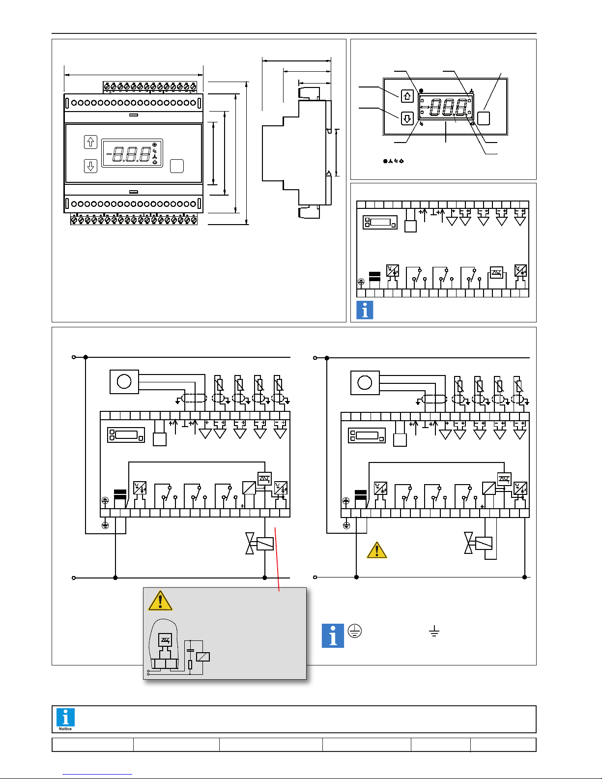
Dimensions in mm,
(in brackets = inches)
Connection EVP 3150-2
Connection of a valve
with 230V AC Input
Connection of a valve with 230V DC Input
Please Note polarity!
Danger of
Destruction!
This manual, which is part of the product, has been set up with care and our best knowledge, but mistakes are still possible. Technical details
can be changed without notice, especially the software. Please note that the described functions are only valid for units containing the software
with the version-number shown on page 1 of this manual. Units with an other version number may work a little bit different.
set up: 26.6.17, tkd/jr checked: 26.6.17, ek/jk approved: 26.6.17, mv/sha transl.(E): ...................... transl()................ corr.
*
Dimensions
59 (2.32 )
39 (1.54 )
35(1.38)
26 (1.02 )
1 2 3 4 95 76 8 1211 1310
EVP
232220 21 2824 2725 26 3229 3130
105 (4.13)
46 (1.81)
63 (2.48)
91 (3.58)
115 (4.53)
181514 16 17 19
ELR EHA
P
373433 35 36 38
1 2 3
4
P
Current version with new display
Front View of the Version with older Display
EV P
P
EL RE HA
LED on = cooling LED on = fan is running
Programming
key
LED on = alarm
LED blinking =
data transmission
LED 7-segment display
for actual values/setpoints
LED's are blinking the same time =
control functions are disabled by digital input or via interface
LED on = defrost
increase
values
decrease
values
this
setpoint
is active
Connection EVP 3150-1
Older product, production discontinued.
DI 1
relay K2
10
29
analog out
EVP 3150-1
24V supply
L
DI 2
main s
21N3L4
N
765 8 9
relay K1
242120 22 2 3
NDO
DO
RS
485
2625 2827
sensor 3
sensor 4
sensor 1
sensor 2
0-10V IN
15
SSR (K4)
230V
AC
11 1 2 1413
relay K3
18
L
230V
AC
16 17 19
N
3430 31 3332 3 735 36 38
* With connecting an inductive load to
the SSR output, like e.g. a relay, it may
be necessary to connect a snubber circuit
in parallel to the load to protect the output
from an uncontrolled turn on.
By an uncontrolled turn on
it is possible that the load is
switched on permanently.
The snubber circuit must be
adapted to the load.
SSR Rela y
RC-G lied
RC-c ircuit
Note
Protective Earth
Earth
Signal out
+ Supply
Ground
8
27
N
N
L
21 3N4 765
L
L
242120 22 2 3 2625
EVP 315 0-2
NDO
DO
RS
485
PT
17109 11 12
230VDC
230VDC
13 1514 16
AC
DC
230VAC
18 1 9
L N
3628 2 9 3430 3 1 3332 3 5 3 7 38
rela y K1
OK/
DI 2
mai ns
analog out
rela y K2
rela y K3
OK/
DI 1
24V supply
0-10V IN
sensor 4
sensor 3
sensor 2
rela y K4
(SS R)
sensor 1
PE
Signal (signal out)
+ Supply
Ground
8
27
N
N
L
N
21 3 4 765
L
L
242120 22 23 2625
EVP 315 0-2
NDO
DO
RS
485
PT
230VAC
171 09 11 12
230VDC
230VDC
13 1514 16
AC
DC
18 1 9
L N
362 8 2 9 3430 3 1 3332 3 5 37 38
OK/
DI 1
rela y K4
(SS R)
rela y K1
rela y K2
rela y K3
24V supply
0-10V IN
sensor 4
sensor 3
sensor 2
sensor 1
OK/
DI 2
analog out
mai nsP E
Page 7
Technical Manual Cold Storage Controller EVP 3150-1 and EVP 3150-2 Page 7
Cooling
Cooling control by Solenoid Valve / Compressor
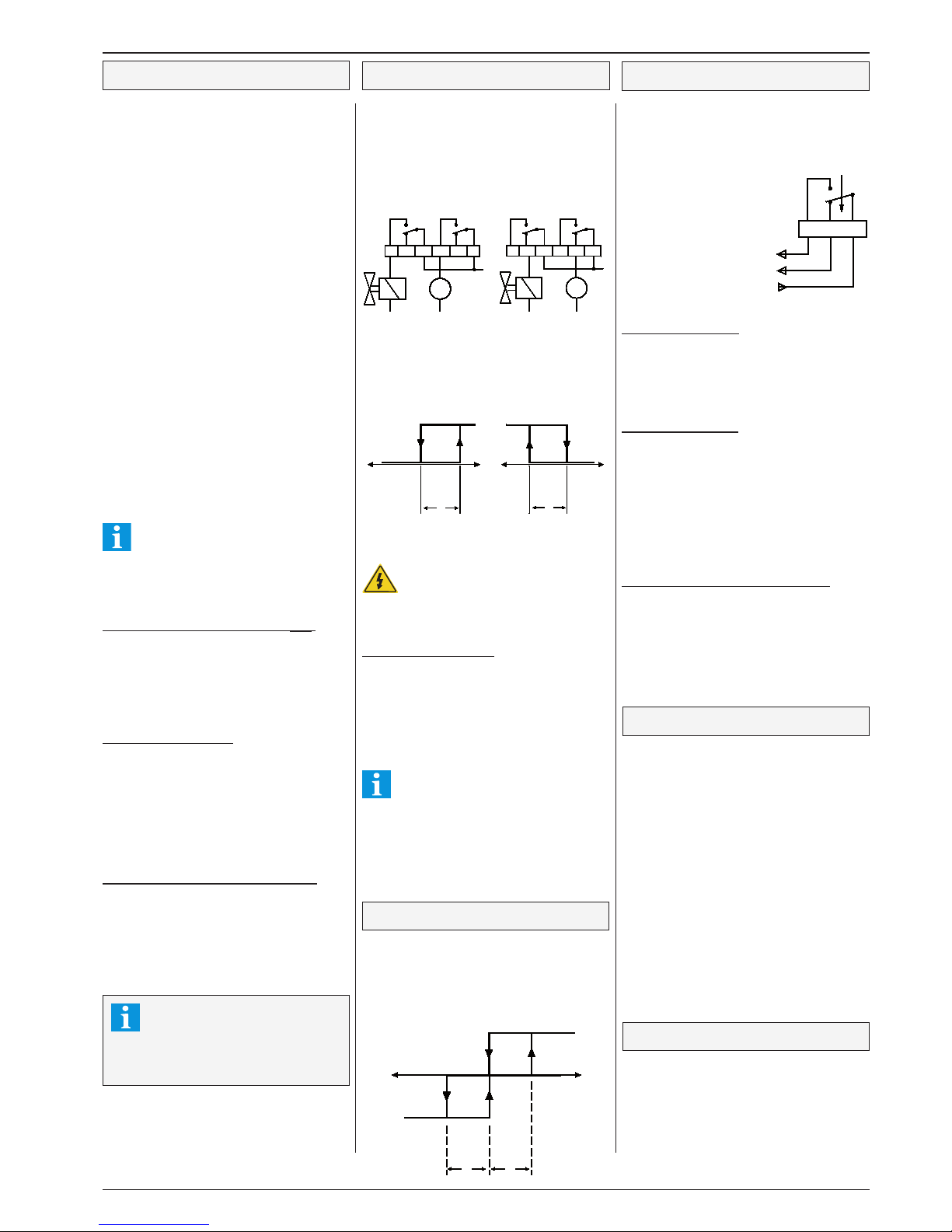
Cooling is controlled by switching the output relay
contacts ON an OFF.
For freezing applications, the N/C contact can be
used (inverted mode) to secure permanent cooling
in case of a controller defect, adjustable by "P03"
(Mode Page).
The point of cut-off is always the valid setpoint. If the
temperature at the control sensor exceeds setpoint
+ hysteresis ("r10", Setpoint Page), the control relay
will switch on. "P03" also affects to the switching
characteristic of the fan relay.
Do not use 'inverted', if compressors are
controlled directly. Risk of compressor
damage by continuous running!
The control relay can be locked via data interface.
Low temperature Limitation
Can be used e.g. for refrigerated shelfs with roller
blinds to limit the temperature at the air outlet during
night operation. When the temperature at the alarm
sensor decreases the limit set by "r43" (resp. "r44",
Setpoint Page) cooling will switch off.
This value is the threshold for the low temperature
alarm at the same time.
The low temperature limitation cannot be
switched off.
Runtime Monitoring
The controller monitors the total running hours of
the cooling output over 3 days. A 'day' is defined
as the period within "P42" and 1 minute before the
same point in time next day.
Example:
"P42" set to 11:00 am =
Monitoring time range is from 11:00 o'clock day 1up
to 10:59 o'clock day 2.
The overall runtime of the cooling relay over a day
will be added and stored ("L21", Actual Values
Page). If this runtime exceeds the value set by "r31"
three days in a sequence, this will cause an alarm
at the hour programmed by "P42" (Mode Page).
The alarm relay will be de-activated and the alarm
LED switches on.
This alarm will be cancelled automatically 1
hour later.
Operation with a single compressor
If a single compressor is controlled by a refrigeration
relay, it is suggestive to have an idle time to prevent
the machine from damages caused by short cycle
operation. The compressor can restart only after the
timer "r33" (Setpoint Page) has been run down. The
remaining time up a restart can be read at "L36"
(Actual Values Page).
Temperature Alarm
If a relay gets the function "ALA", a temperature alarm
will be forwarded by the 'Quiescent current' principle.
After power-up of the controller, the alarm relay will
be energized after ~4 sec. In case of a failure the
relay will be de-energized after a delay timer ("r45",
Setpoint Page) has
been run down. LED
"Alarm" shows the
alarm state. If temperature comes back to
the normal range, the
relay will be energized
again. "L32" shows
the remaining time up
to an alarm.
Overtemperature Alarm
It is possible to select max. 4 (5 with the 'virtual') alarm
sensors (e.g. 4x "ALA"). If the temperature at one of
the alarm sensors exceeds the control setpoint + the
"r41" (resp. "r42", Setpoint Page) setting, an alarm
will be initiated after the delay time "r45".
Low temperature Alarm
If the temperature at any alarm sensor gets lower
than the "r43" (resp. "r44", Setpoint Page) setting,
an alarm will come on with the delay explained
above. This setting is an absolute value and does
not refer to the control setpoint. At the same time, this
setting works as threshold for the "low temperature
limitation" function.
Low temperature alarm can be disabled by "P41"
(Mode Page).
Supplementary alarm delay during defrost
After a defrost cycle the temperature may take longer
to stabilize and the normal alarm delay turns out to
be too short. For this reason the value of parameter
„d33“ (defrost page) will be added on to the normal
alarm delay after defrosting.
cooling relay normal cooling relay inverted
Heating function
One relay is able to work as a heat relay. Then the
control setpoint is the cut-off of heating and cooling
at the same time. Cut-in will be:
•
for cooling: setpoint + hysteresis (r10)
• for heating: setpoint - hysteresis (r10).
'Physical' and 'virtual' sensors
1. Each 'physical' (real) sensor is able to fulfill up to 3
functions at the same time (see Assignment Page),
any sensor is able to do the same job.
Up to 4 control sensors can be assigned the same
time. If one of them gets warmer than setpoint +
hysteresis, then cooling starts.
2. It is possible to create a 'virtual' sensor to realize
different kinds of averaging, e.g. multiple sensors in
a huge room or averaging of inlet and outlet sensor in
a chest freezer. The 'virtual' sensor resp. value (L07)
follows from the selectable emphasis of the sensors
which must have an effect on the result (h17, h27,
h37, h47, Assignment Page). The functions assigned
to this 'sensors' (h71, h72, h73, Assignment Page)
are the same as the functions for the 'physical' sensors.
Example: If the 'physical' sensor 1 got the function
"con" (control sensor) and also the 'virtual' sensor,
then the warmer one initiates refrigeration.
- Selection of a "virtual sensor":
- Assignment of a function by h71-h73
- Selection of a 'physical' sensor which must have
an effect on the result :
- Activating of the sensor by assigning a
function (e.g. display only sensor)
- Set emphasis for the selected sensor
(
h17, h27, h37, h47).
The sum of all emphasis values must be
100%. Example:
If sensor 1 and sensor 2 must have an effect
on the result and you set "h17" to "30%" and
"h27" to "60%", then you get the error message "SEL"
(assignment error).
Further causes for the error message "SEL"
- The sum of all emphasis parameters is 100%,
but no virtual sensor function is selected
- All 4 emphasis values are set to '0' and a
'virtual' sensor function is assigned
- A physical sensor is switched off, but an
emphasis value > 0 is selected.
Example 1, Chest Freezer:
For the detection of the actual value, inlet and outlet
sensor must be used. Sensor 1 is mounted at the
suction side (inlet) and must have an 60% influence
on the result. Sensor 2 is mounted at the outlet and
must have an 40% influence.
- set "h17" to "60"
- set "h27" to "40"
- set "h71" to "con" (control sensor)
Example 2, huge room, standard application
Sensors 1-3 must measure the rooms temperature,
an arithmetic average must be calculated, sensor 4 is
the defrost limitation sensor in the evaporator.
- set "
h17", "h27" to "33" and "h37" to "34"
- set "
h71" to "con" (control sensor)
- set "
h41" to "df1"
Special Function
If an emphasis parameter value is set to
100% (others to 0), up to 6 functions can
be assigned to the corresponding physical sensor.
This may be of interest for applications where
more than 3 sensor functions are used.
M
L
M
L
cooling fan cooling fan
P03 set to 'nor'
P03 set to 'in'
active-
passive
phase
cooling = relay on relay on
freezing=
relay off
cold warm
warm
cold
setpoint
setpoint
Hysteresis
Hysteresis
relay off
refrig. on
Heizen ein
cold
warm
off
setpoint
Hysteresis
Hysteresis
Page 8
Technical Manual Cold Storage Controller EVP 3150-1 and EVP 3150-2Page 8
Second setpoint (night operation)
A second setpoint can be defined by "r03" (Setpoint
Page). This can be used for night operation or other
energy savings. Switching between these setpoints
can be made by internal clock or by digital input. The
current used setpoint is marked by a lighted decimal
point in the parameter display. On the 'Actual Values
Page', parameter "L43" shows the current state.
Internal switching
The parameters „P21“ and „P22“ determine
the 2nd setpoint period. If the internal timer is not
used, set both times to "oFF".
External switching
The digital inputs can be configured for
external switching, selectable as "dnL"
(active low) or "dnh" (active high). After the
input has been activated, the 2nd setpoint is
active all time and the internal timer is disabled.
If you want to use external switching only,
please set „P21“ and „P22“ to "oFF".
Second Set of Setpoints
The controller offers two complete setpoint sets
including day/night setpoints and alarm limits.
Example Application: By an external switch it is
possible to change a cold room from refrigeration
to freezing for temporary storage of other products,
without changing any parameters at the controller.
Even here the currently used setpoint is marked by
a lighted decimal point in the parameter display.
Toggling between the setpoint layers
1. internal: by parameter „r01“ (Setpoint Page)
2. external: assign function „
SEt“ to a digital
input. If connected to mains phase,
the 2nd layer is in use.
Light Control
One of the relays is able to control room lightings
(function "LIt"). In this case, the relay switches
together with the night settings.
While 'day'-operation the light relay keeps energized.
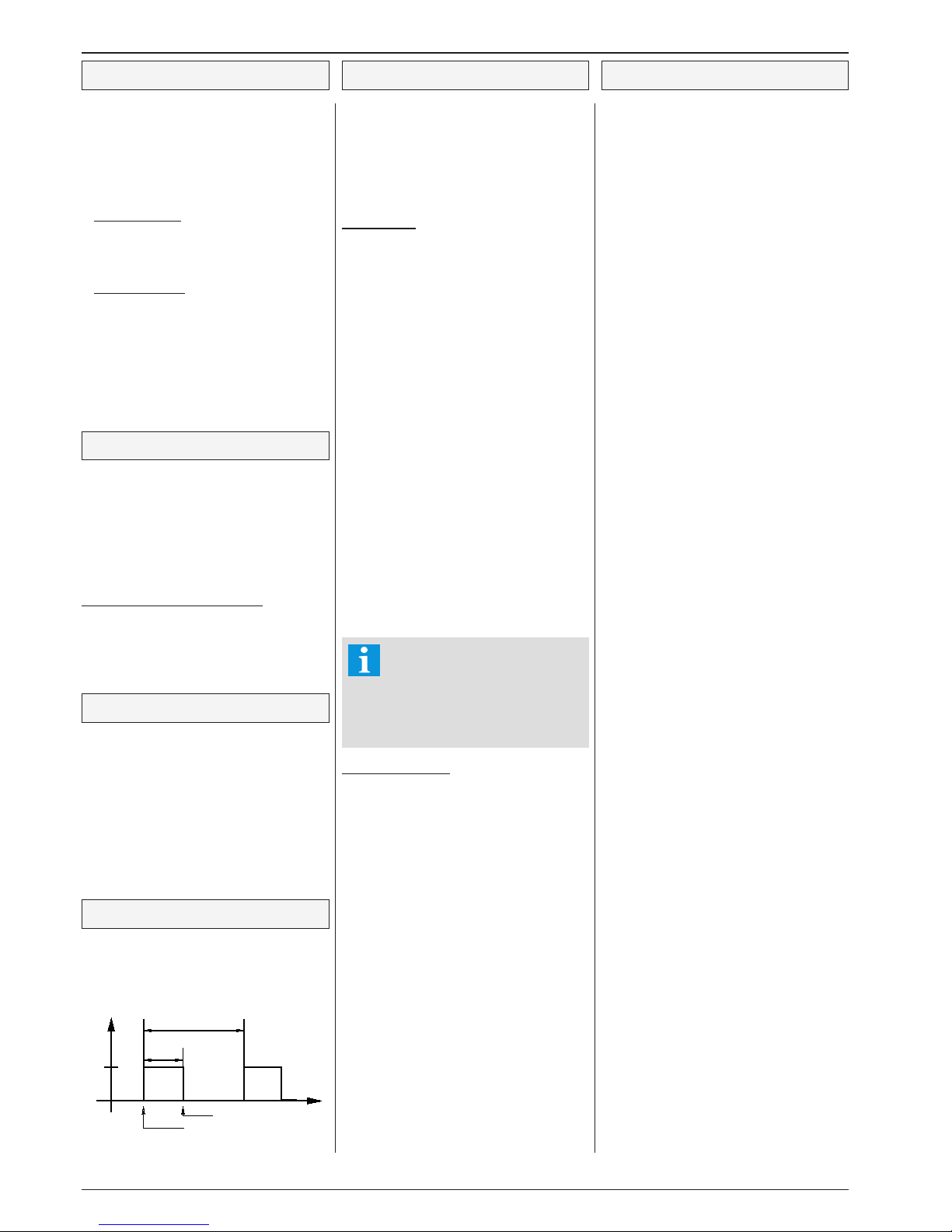
Emergency Operation
If all control sensors fail, the unit turns to an
emergency mode automatically. The cooling relay
cycles with a %-part (P04, Mode Page) of a 30
minutes period.
Digital Inputs (Optocoupler Inputs)
Switching OFF the controller unit
Sometimes it is necessary to switch off cold storages
completely including the controller.
If the controller works in a network, the bus-master
so detects a malfunction and generates an alarm.
To prevent this, the unit must be switched OFF via
digital input.
Controller OFF
If a digital input is assigned to the functions "oFL"
or "oFH" and is activated by the matching signal,
then all control functions will be disabled. All alarm
functions are locked and the display shows "oFF".
Safety Chain Monitoring
When using the controller for single compressor
applications, one of the digital inputs can be used
to monitor the safety chain ("chA").
Normally the digital input is connected to phase via
this chain of contacts. If the chain opens, cooling
and fan will switch off, a running defrost cycle will be
terminated and a new defrost cycle is impossible.
Parameter "r46" defines the response time on the
missing signal voltage.
Door Contact Input
If a digital input with the function "dor" is connected
to phase, the evap fan stops immediately. The control
range of the EEx-Valve will be changed automatically
to avoid a further evaporation.
If the door is open > 3 minutes, cooling will be
stopped. All other functions continue working.
If the door is open > 5 minutes, the unit generates the
error message "rdo". After the timer "r62" (Setpoint
Page) has been run down, cooling restarts and an
alarm message will be forwarded.
Door open monitoring
Every time a door is opened, the controller adds
the time to the total opening time of the present day
"L22" (Actual Values Page). If the total opening time
exceeds the value set by "r32" (Setpoint Page), an
alarm will be generated.
The alarm message will be forwarded at the point in
time determined by "P42" (Mode Page) and will be
cancelled automatically 1 hour later. "L31" shows
the remaining time up to the alarm message.
External Alarm
The digital inputs are able to process external alarm
messages. For this, the function "ALA" must be
assigned (Assignment Page).
While normal operation, the input is connected to
mains phase. When the voltage drops down, a delay
time starts ("r61", Setpoint Page). After this timer has
been run down, an alarm will be forwarded.
Exception:
If no alarm sensor is assigned or if
the temperature is above the alarm
limit, cooling continues without interruption. The cooling keeps switched
ON and the fan starts again, so the
door opening is ignored.
Real Time Clock
The built-in real time clock has a buffer for max. 10
days without mains voltage. Date and time can be
set by "P82"..."P87" (Mode Page).
An automatic summer / winter switch ("P81", Mode
Page) considers the current EU-rules from 1996 (EU
96), but can also be switched off.
30 minutes
emergency ON
in %
ON
OFF
cooling OFF
cooling ON
Page 9
Technical Manual Cold Storage Controller EVP 3150-1 and EVP 3150-2 Page 9
The EVP 3150-2 is able to control one (1) cold storage with an evaporator equipped with an Electronic
Expansion Valve (EExV).
In such applications, the EExV takes over the
jobs of the former solenoid valve and the compulsive thermal expansion valve.
Expansion Valves
The EVP is able to drive pulse-width modulated,
cycling expansion valves and valves with ther-
mal drive.
AC or DC type valves can be used, they are supplied
by mains voltage via SSR-relay with 2 outputs.
Missmatches valve/nozzle and evaporator will be
compensated in a wide range. Because the valves
need no high pressure difference to open, it's possible
to work with low condensation pressures, as long
as the configuration allows that.
From this it follows a higher COP-value for the
compressor and so an option for energy saving. The
energy saving depends on outdoor temperature (if
the condenser is located on the roof) and is higher
in winter than in summer.
By the optimal filling of the evaporator and the more
equable icing an additional energy saving of 2 - 5%
is possible.
Measuring Methods
The EVP is able to work with 2 measuring
methods:
1. Pressure Transmitter and Temperature Sensor
at the evaporator outlet, this is equivalent to the
arrangement of a thermal expansion valve.
2. 2 Temperature Sensors at the inlet and the
outlet of the evaporator.
The unit always controls the 'virtual' aperture
size of the valve to reach an optimal filling
and so the optimal efficiency ratio of the
evaporator. Period time and pulse-width of
the PWM-control are defined by the control algorithm
(autoadaptive), disturbances like suction pressure
fluctuations and flashgas will be filtered out.
1. Pressure / Temperature method
To capture the superheat, a pressure transmitter with
2-10V output signal and a TF 501 temperature sensor
at the evaporators outlet is used. The arrangement
of this parts is equivalent to the components of a
thermal expansion valve.
This method is strongly recommended
for single machines or plants with just a
few evaporators. The compressor can
be controlled by an external suction
pressure switch or the cooling relay of the EVP.
By this, special operating modes and an automatic "pumpdown" function are possible.
Variable Overheat Control
If you get a difference by the settings of P60 (Superheat, minimum value) und P65 (Superheat,
maximum value), then the superheat will be
shifted by the control algorithm within the ONpoint (setpoint+hysteresis r10) and the OFF-point
(setpoint). If the function is disabled, the superheat
value is determined by P60 only.
Function is disabled:
P65 (Superheat, maximum value) exceeds P60.
Function enabled:
P65 is below or equal to P60.
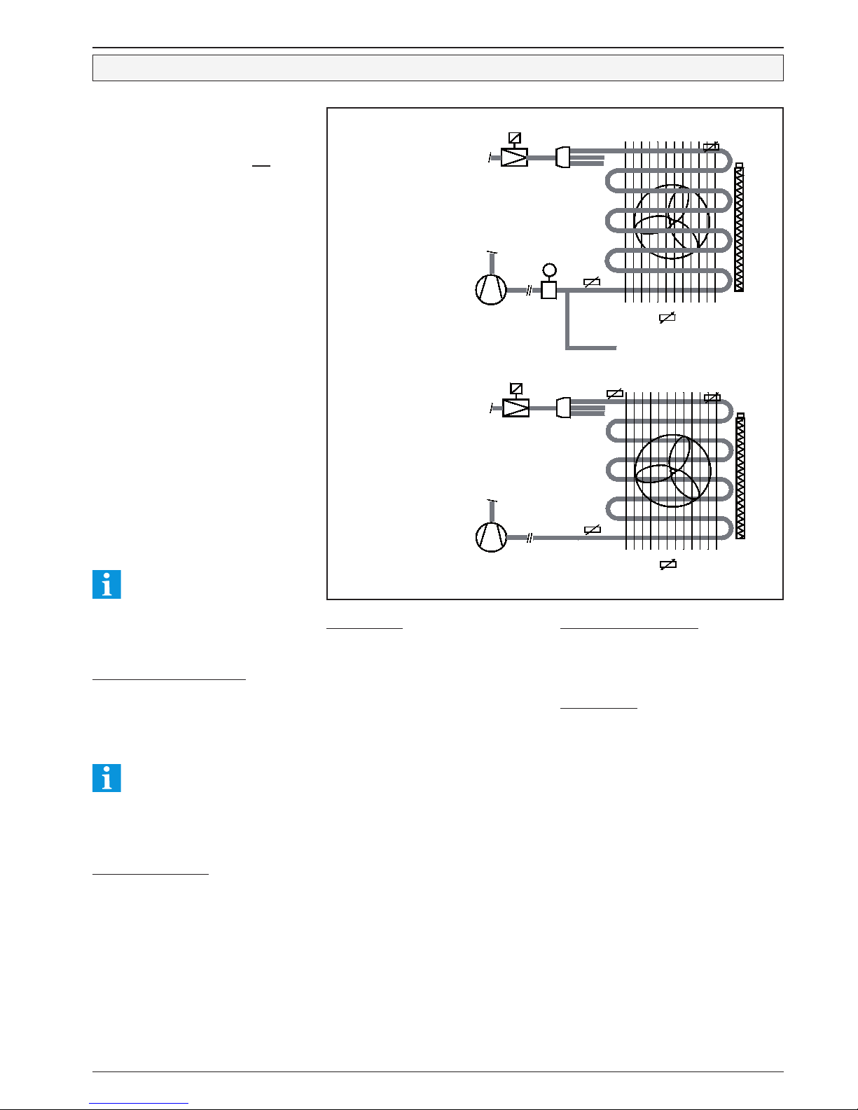
Temperature control with Electronic Expansion Valves
Sensor Positions
Pressure Transmitter/
Temperatur Sensor method
2 Temperature Sensors method
Parameterization
The following recommendations refer to the pressure
transmitter "DG -1/9 2-10V".
L05 ...........Display of the temperature which is
calculated from pressure value and
refrigerant
L09 ...........Actual Overheat Value
P55 ...........Method is active as soon as the used
refrigerant is selected.
P53 ..........Lower limit of transmitter
(-1.0, relative pressure)
P54 ..........Upper limit of transmitter
(+9.0, relative pressure)
P56 ..........Lower voltage limit of the pressure
transmitter input. (2V. Below this 2V,
an error message is generated).
P57 ..........Upper voltage limit of the pressure
transmitter input (10V).
P60 ...........Superheat setpoint, minimum value
(depends on evaporator)
P61 ...........MOP-setpoint (Maximum Opening
Pressure, i.e. limitation of the
evaporation temperature at the outlet.
Depends on compressor resp. plant).
P65 ...........Superheat setpoint, maximum value
The settings of P60/P61 depend on the used com-
pressor and the used evaporator.
P62 ...........P-Part of the Expansion Valve Control
P63 ...........I-Part of the Expansion Valve Control
The factory settings of P62/P63 are almost ideal for
all kind of cold storages, changes must be made
with care.
After this basic settings, all other relevant parameters
must be set.
2. Temperature sensor method
To capture the superheat, 2 temperature sensors
(TF 501) are used, one at the inlet and one at the
outlet of the evaporator. For this method, no pressure
information is necessary.
Parameterization
P55 ......Must be set to 0, i.e. no refrigerant
selected. Inlet- and outlet sensor must be
assigned. No further parameterizing
necessary, except standard settings.
Limitation of the EEx-Valve Signal
With this function (P66) the maximum opening of
oversized expansion valves can be limited. It affects
on all possible expansion valve output signals:
- Analogue output assigned to an EEx-Valve
- Expansion valve relay
Actuating Variable Delay for EEx-Valves
P67 (setep size) and P68 (output delay) affect as
actuating variable delay for the Electronic Expansion Valve, both for the analogue output as well as
the relay output. The OFF-value (0%) will be initiated immediately with:
- Controller OFF
- Defrost initiation
Information
Parameter "L42" (Actual Values Page) shows the
state of the EEx-valve permanently.
P
defrost heater
evaporator sensor
(defrost limitation)
control sensor
at air inlet
(room sensor)
EExp. Valve
Druck-
geber
Outletsensor
further evaporators
defrost heater
evaporator sensor
(defrost limitation)
EExp. Valve
Outletsensor
Intlet-
sensor
control sensor
at air inlet
(room sensor)
Page 10
Technical Manual Cold Storage Controller EVP 3150-1 and EVP 3150-2Page 10
The EVP allows several, different defrost methods.
Up to 3 defrost relays can be assigned. This relay
output(s) then control an electric heater or fan which
defrost the evaporator(s).
Each evaporator with electric heater is monitored
by a defrost termination sensor.
According to the application, the fan can stop or run
during the defrost cycle.
●"d02" (Defrost Page) fixes the defrost initiation
mode.
- "Etn" : Defrost is initiated by a digital input
- "
Int" : Defrost can be initiated by digital
input or the internal time-switch.
- "
AdA": Defrost is controlled by the intelligent
(adaptive) defrost algorithm
Electric defrost heaters are always switched by the
N/O contact of the defrost relay. "L33" shows the
remaining time up to the end of the defrost cycle.
Defrost release by internal timer
With parameters "d11"..."d16" (Defrost Page) you
set six (6) possible defrost release times. This
points-in-time can be set in 10 minute steps only,
that means a defrost time like 6:55 is impossible.
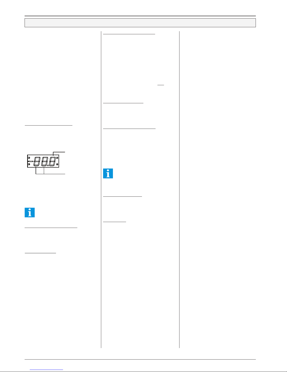
Times on the display:
The precondition for the start of a defrost cycle is
that at least one of the defrost termination sensors
detects a temperature below limitation temperature.
If parameter "d02" is set to "Etn" (external only), a
defrost cycle cannot be initiated by the timer.
Please note that this function differs
with the 'adaptive' defrost method
External (Remote) Defrost Initiation
To start de-icing by a digital input, note that mains
phase has to be applied for 2 seconds minimum
and last not longer than the shortest possible
defrost cycle.
Break before defrost
Parameter ‘d38’ (defrost page) effects a delayed
energizing of the heater at the beginning of the
defrost cycle. By this, the rest of the evaporators
chillness can be blown to the storage.
The defrost heaters must deliver less energy,
because the evaporator is already warmed up.
Defrost termination by temperature
The EVP controller is able to work with up to 3 defrost
relays (= evaporators). Defrost is individually teminated for each defrost output by the corresponding
defrost (evaporator) sensor. This evaporator sensor
must be placed at a position where, by experience,
ice remains the longest time. If the temperature rises
at that position, the ice in the evaporator is probably
melted completely.
A defrost cycle is completed as soon as the defrost
sensor has reached the defrost limitation temperature "d31" (Defrost Page).
If 2 defrost sensors are assigned, both sensors
must achieve the limitation temperature to termi-
nate defrost.
Defrost termination by time
If no defrost sensors are assigned or if they are out
of order, the defrost cycle will be terminated after
"d32" (Defrost Page) has been run down. "L33"
shows the remaining time up to termination.
Defrost termination time monitoring
The unit captures the number of defrost cyles which
are terminated by time (min. 1 defrost term. sensor
must be assigned). If the number of defrost cycles
terminated by time exceed the number programmed
by "d37" (Defrost Page) an alarm message will
be generated. With this function, massive icing or
defective defrost heaters can be recognized timely
and reliable.
In case of airflow-defrost without evaporator sensor, this function must be disabled
("oFF"), because here every defrost will be
terminated by timer and no alarm message
is desired.
Cooling Delay (drain time)
After defrost is terminated, the solenoid valve keeps
locked for the time set by "d35" (Defrost Page).
"L34" shows the remaining time up to the restart
of cooling.
Manual Defrost
A manual defrost initiation is possible at any time.
To start manual defrost:
Select "d50" (Defrost Page),
set it to "on" and confirm.
Stop manual defrost
Select "
d50" (Defrost Page),
set it to "
oFF" and confirm.
3rd position =
Minutes x 10, that
me ans no si ng le
minutes will be displayed
1st/ 2nd position =
hours
Pulsed Defrost
To save energy it’s possible to work with a pulsed
(switched in intervals) defrost function.
If the evaporator temperature is located within "d34"
(Defrost Page) and the limitation temperature "d31"
(the value of "d34" must be lower than limitation
temperature), the controller determines about the
optimal heat distribution in the evaporator depending
on the gradients of the temperature. The heater will
be switched on in controlled periods until the defrost
limitation temperature is reached.
The result of this procedure:
● Heat energy in the evaporator will be distributed
much better
● Defrost limitation temperature can be set to a
lower value
● Less of humidity in the chamber
● Save of energy
Defrost
Page 11

Technical Manual Cold Storage Controller EVP 3150-1 and EVP 3150-2 Page 11
Intelligent Defrost (adaptive defrost) for Walk-In Coolers
Main Characteristics
This defrost control method, developed in cooperation with the ‘GÜNTNER’ company, fits
especially for cold stores and freezers which
are closed (like walk-ins).
It is less efficient in applications where
the limitation sensor is located in the
airflow (e.g. open chest freezers).
This technique reduces significantly the
amount of energy the refrigeration plant
needs.
Especially while difficult situations (like high
air-humidity, in cool-down chambers, while long
opening times of the door of the cold storage
room, uneven feeding of the cold storage
room, etc.) the adaptive method protects the
evaporator from glaciation safely.
Dynamic ‘room-feeding’ situations engage
the controller to adapt itself to the new
situation, without expensive adjustment
by technical personnel.
Specialized sensors or additional probes
are not required.
Parameterization is very easy:
● set parameter "d02" to value "AdA"
(adaptive)
● set parameter "d05" (Defrost Page)
to a value which is 2 or 3 times the
normal defrost interval.
Within this period the algorithm
decides independly about the point
in time to defrost. After the end of this
period defrost starts in all cases.
● parameter "d04" (Defrost Page)
shows the time up to the next defrost.
● parameters "d34"
and
"d31" define the range the heater will
be pulsed within.
Process Sequence
1. If [setpoint + hysteresis > 2,5°C] the
controller uses the fan to reduce icing.
2. In the time period set by „d05“ the controller
decides itself if and at which moment a
defrost cycle is necessary. If icing is
detected, the controller prepares defrost
and begins either immediately or at the
next allowed defrost time.
3. Cooling stops, the fan goes on turning a
certain time
4. The fan stops and the defrost heater starts
5. If several evaporators are installed,
each one has its own defrost sensor and
heater relay, so it is individually heated.
6. After achieving a defined evaporator
temperature, the heater will be cut on/
off in calculated periods. The period lenghts
depend on evaporator temperature.
7. Defrost heater cut off, limit temp. is reached.
8. Cooling and fan remain still off (drain time).
9. After the end of „d35“ cooling starts, but the
fan remains still off.
10. After end of „r22“ the fan starts and normal
refrigeration goes on.
Refrigeration
Even during normal operation the fan stays on after
cut-off of cooling to reduce icing.
Recognition of icing
The more ice on the fins the more increases the
difference of temperature between the roomsensor
and evaporator sensor. The controller uses the value
of these sensors, their difference, the historic curves
of these values as well as curves and duration of
the past defrostings to calculate the necessity of
defrosting.
Use of latent energy by airflow
We recommend to use "d03" (defrost forerun, defrost
page) to switch on the fan several minutes ahead
the defrost cycle, while cooling stops and the heater
is not yet on.
Additionally, the fan is switched on automatically at a
certain difference between the sensors. By this, the
„cooling-energy“ is brought out of the evaporator and
stored in the chamber. This helps also to reduce the
amount of heat energy necessary to defrost.
Defrost start
If all six parameters release times are set to Off, the
controller decides itself when it starts defrost.
● Further time influence
If you want to prevent that defrost starts at
certain day-times use all the defrost release
times and set them to points in time where
defrost is allowed. If no icing is detected,
these times will be ignored.
On the other hand, once icing detected, the
controller will wait for the next defrost release
time before starting a defrost cycle.
● External command
Assign one of the digital inputs to "deF". By
applying voltage to that input it is possible to
start defrosting at every moment.
Defrost heating
When „d34“ is achieved, the heater will be cut off.
The heat energy of the resistances will dissipate
slowly and melt the ice. The length of the cut-off is
calculated by the controller and as soon as some
criteria are fulfilled, it will switch on the heater again.
The heater will be pulsed until the temperature of
the evaporator sensor reaches the defrost limitation
temperature "d31".
This procedure fits in the same way for the case of
several evaporators in the chamber.
By this way defrost period will take longer, but
will be more efficient.
Several evaporators in one chamber
For certain plants it is necessary to use several
evaporators in one chamber. The controller is able
to control up to 3 evaporators in one chamber. Even
in this case one unique room sensor is sufficient.
E.g. for a chamber with 3 evaporators you need
only 4 sensors:
● one controlsensor
● three defrost sensors (one for each evaporator)
If a defrost cycle is necessary, all evaporators will start
defrost at the same time to avoid short circuit of air,
when one is heating and the fan of another is turning.
The one with the highest rate of icing determines the
start of the defrost cycle. The EVP controller units are
capable to determine just this evaporator and
even to adapt it when conditions change.
Thus always the evaporator with the most ice
initiates defrost start, nevertheless the quantity of
energy which is necessary to defrost will be calculated
for each evaporator separately.
To finish defrost cycle all evaporators must have
reached the defrost limitation temperature.
Emergency Operation Mode
In cases the controller recognizes that it would be
incapable or to slow to control the process, or when
it gets not enough information, e.g.:
● charge of unusual very humid goods
● freezer door was open a very long time
● the evaporator is sprinkled with water
● sensor broken or shortened
● defrost terminated by the max. defrost time
the emergency operation starts.
To detect malfunction of the defrost control the unit
uses the increasing of "d05".
If a defrost cycle is terminated by this time, the
controller starts several defrost events with the interval corresponding to (¼) one quarter of the time
programmed by "d05".
Therefore be careful in choosing the time for
this parameter.
After the end of the disturbance the controller works
on normally.
Example
Max time to defrost is set to 24 hours. If defrost
is not terminated by the evaporator sensor,
the controller will start defrost cycle every
24 / 4 = 6 hours until a cycle will be finished by
the evaporator sensor and not by timer.
Independent from this procedure, a failure
message will be initiated.
End of defrost
When the defrost sensor has reached the defrost
limitation temperature "d31", the heater stops and
the controller waits until "d35" has expired, to allow
the melted water drop to the drainage.
While the following 'drain-on' time ("r22", Setpoint
Page) cooling starts, but the fan still stay OFF to
prevent that the fans blow warm and humid air or
water drops into the chamber.
Further information about possibilities to use
latency heat you can find under "Evaporator
Fan Control"
Page 12
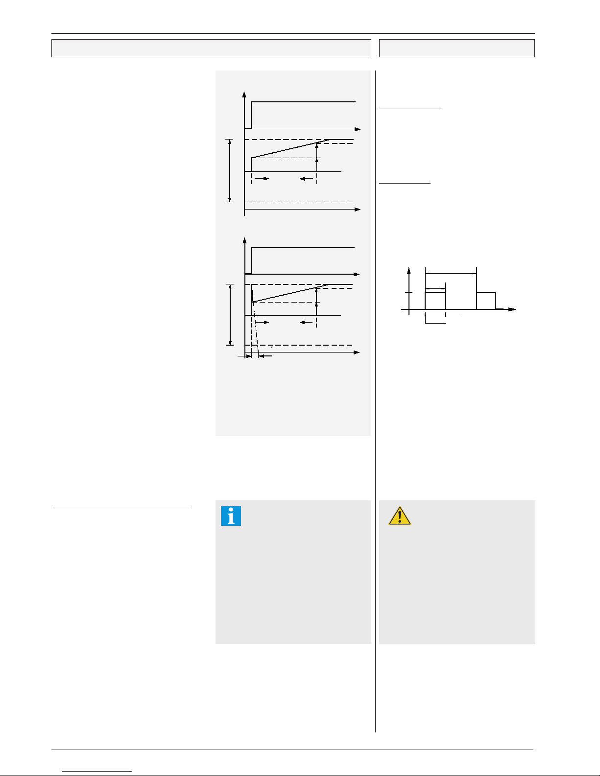
Technical Manual Cold Storage Controller EVP 3150-1 and EVP 3150-2Page 12
Analogue Output
The analogue output can be used for regulation
purposes or to provide a remote display with an
actual value image. The signal is available as a
DC-Voltage or a DC-Current-Signal, fixed by "h51"
(Assignment Page).
Parameter "L50" (Actual Values Page) shows the
current output signal as a %-part of the selected
range, "h52" (Assignment Page) determines the
behaviour of the output:
Test functions
"h52" = "0" output signal is 0V resp.
4 mA (fixed)
"h52" = "100 output signal is 10V resp.
20mA (fixed)
Transmission of actual values to remote displays
or similar
This function allows the analogue outputs to deliver
a mirror of measured actual value.
Normally a control probe will be used. If multiple
probes are configured, the warmest actual value will
be used. If a virtual probe is configured, this probe is
used in the same way as a real probe.
"h52" = "dIS" The output provides an image
of the value of cooling sensor 1.
U-output: -50°C = 0V,
+100°C = 10V
I-output: -50°C = 4mA,
+100°C = 20mA
Control with the analog output signal (PID-control)
"h52" = "P" PID-controller, whose output
signal represents an addition of
the components P, I, D and T1.
"h52" = "Pr" PID-controller like above, but
with inverted output (rising
temperature = falling signal).
To adapt the controller to the process use the following parameters:
"r51" = PID proportional band,
located symmetrically
around setpoint 1
"r52" = PID-integral time (I-part)
"r53" = PID-derivative time (D-part)
"r54" = PID-actuator response
time (T1-part)
How to influence the analog output manually
For certain applications it may be useful to affect
the output signal manually. Any digital input can be
assigned to a function "AnA". Once activated, the
analogue output delivers a predefined voltage- or
current signal, e.g. to drive a valve to a specific
position.
"h61" or "h62" set to "AnA" (Assignment Page)
= configure digital input 1 or 2
"r63" (Setpoint Page)
= amount of the output in % of the selected
range, if the digital input is activated.
Example:
Digital input OK/DI1 is configured at "h61" to the
value "AnA", "r63" is set to "50".
If the analogue output works as voltage output,
it delivers 5V DC. If it works as current output, it
delivers 12 mA.
Electronic Expansion Valves
with analogue input
The analogue output is able to control
expansion valves with analog input.
Therefore, "h52" must be set to "EEP".
Also in this case, "h51" serves as a switch
for a voltage- or current output.
PI-control, D and T1-parts de-activated
PID-control, T1-part de-activated
Control Characteristic
Actuating Variable Delay for PID
For using control processes with large reaction
times the controller offers an 'Actuating Variable
Delay'.
1. Analogue Output
If the controller sends a signal which initiates the
analogue output to rise or to fall, then an adjustable
delay time (r56, Setpoint Page) starts. Within this
time period, the output signal is able to alter only
by a specific %-part (step size, r57).
If "r57" is set to "100%" and "r56" to "0", then the
function is disabled.
2. Relay Output
In applications with motorized actuators, the
Actuating Variable Delay takes effect by clocking
the cooling resp. heating relays. If the controller
sends a signal to initiate a relay permanently ON,
an adjustable time period "r58" (Setpoint Page,
Cooling/Heating Relay Time Period) starts. Within
this period, the relay is engaged for the time set
by "r59" (Setpoint page, Cooling/Heating Relay
ON-Time).
If "r59" is equal to "r58" or exceeds it, then the
function is disabled, the relay switch as normal
again.
Reaching the The OFF-value
The OFF-value (0%) will be initiated immediately
with:
- defrost initiation
- solenoid valve lock
- safety chain error
- controller OFF
- cooling OFF with an open door
Important !!
Please note the decreased lifetime of
the relay contacts in cycling operation. Please care for a suitable relief.
Cycle 40 sec.:
load current 0,8A res. --> 5 years
load current 1,2A res. --> 2,5 year
load current 1,9A res. --> 15 months
(Theoretical values according to the
relays data sheet)
r58 (s)
r59 (s)
ON
OFF
relay off
relay on
t
t
PID
integral time
I-part
P-part
5V resp. 12mA
max.
min.
proportional band
output
setpoint
deviation
t
t
PID
integral time
I-part
P-part
5V resp. 12mA
max.
min.
proportional band
output
setpoint
deviation
PID attack time
Page 13
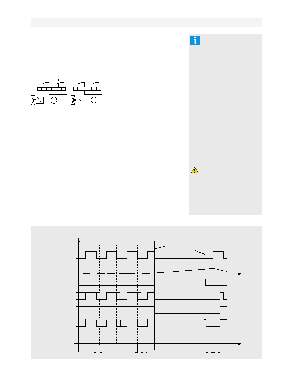
Technical Manual Cold Storage Controller EVP 3150-1 and EVP 3150-2 Page 13
ein
aus
ein
aus
ein
aus
aus
ein
aus
ein
2
1
defrost starts
defrost ends
cooling
limitation temp.
evap. temperature
defrosr
Interval fan
electric heater
permanent fan
electric heater
interval fan
airflow defrost
fan off delay
1. pause after defr.
(drain time)
2. fan start
delay
Evaporator Fan Control
Each output relay can be configured for evaporator fan control. The fan control depends on the
following parameters:
P03 ..... (cooling mode, Mode Page)
"
reF" = refrigeration, fan will be switched
by the N/O-contact of the fan relay
"FrE" = freezing, fan will be switched by
the N/C-contact
P02 ....(fan operation, Mode Page), defines
the characteristic of the fan during the
cooling period.
"Int" = fan runs together with solenoid
valve/compressor
"PEr" = fan runs continously while
cooling
"Add" = Using of latency heat by a special
fan control + "Special mode for room
temperatures > 2,5°C", as described in
chapter "Intelligent Defrost".
d01 .... (fan during defrost, Defrost Page),
defines the fan characteristic during
the defrost cycle.
"on“ = during defrost, fan runs
continuously
"off“ = fan is stopped during defrost.
Fan operation modes, defrost termination using electric heaters
Fan start-up (freeze-on) delay
The start-up time delay for the fan after defrosting
is defined by parameter "r22" (Setpoint Page).
This avoids that water drops will be blown into the
chamber. "L35" (Actual Values Page) show the
remaining time up to the fan will switch on.
Examples for fan operation modes
1. fan in permanent mode
This mode is mainly used in refrigerated
shelfs, refrigerated display counters and
chest freezers
● fan is directly connected to mains voltage,
not connected to the controller unit
or
● a relay is reserved for fan control, "P02" is
set to "PEr", "d01" is set to "on".
Drain-time "d35" is set to "0".
2. fan interval mode, defrost by fan
A relay is reserved for fan control, "P02" is
set to "Int", "d01" is set to "on".
3. fan interval mode, defrost by electric heater/
hot gaz:
A relay is reserved for fan control, "
P02" is
set to "Int", "d01" is set to "oFF". The fan
runs while cooling is on, will be disabled
during defrost periods and comes on after
defrost with a time delay set by parameter
"r22".
4. fan in permanent mode and defrost by
electric heater
A relay is reserved for fan control, "P02" is
set to "PEr", "d01" is set to "oFF".
The fan will run continously and stops during
a defrost period only.
Chances to exploit Latency Heat
1. Fan operation mode P02 = "Add"
- If temperature falls, cooling and fan will
stop with reaching the control setpoint.
If the room temperature rises to a value
equal to
Control Setpoint + 1/2 Hysteresis,
the fans restart under the condition that the
temperature of the evaporator (detected
with limitation sensor) is lower than
Control Setpoint - 1/2 Hysteresis.
So remaining coldness will be blown into the
room which reduces the number of
compressor starts.
- Evaporators can be de-iced already at
temperatures from 2°C by forced air.
When cooling stops, fans are turning on until
ice and frost are melted (limitation calculated
within 2...5°C, cooling switches on at -3K).
Thus humidity stays in the chamber which
will improve the quality of certain goods like
meat or vegetables.
Additonally to the compulsatory "fan trailing
delay
" (r23, fan is forced to continue turning
after cooling reached the setpoint and stopped),
the fan will turn from a specific temperature
[setpoint + hysteresis => +2,5°C] until the
evaporator sensor has reached a certain
value.
At room temperatures [setpoint+hysteresis
=> +2,5°C] notify to set parameter "d05" to
a higher value, because a defrost start is
forced if this time is past.
2. Fan trailing delay
To utilize latent energy, the fan is able to run
for up to further 30 minutes after the cut-off of
valve or compressor ("r23", Setpoint Page).
M
L
M
L
cool. relay fan relay cool. relay fan relay
refrigeration
freezing
Page 14
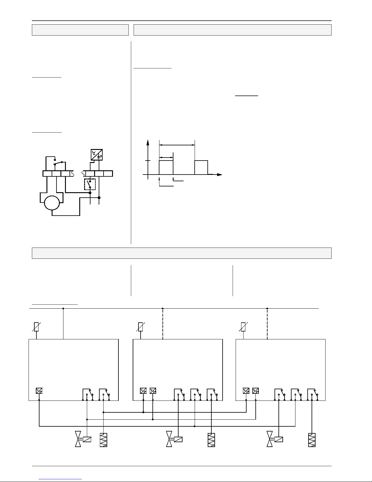
Technical Manual Cold Storage Controller EVP 3150-1 and EVP 3150-2Page 14
leading controller unit
(master)
guided controller unit
(slave)
guided controller unit
(slave)
control sensor
defrost termina-
tion sensor
cooling lock
external defrost
cooling release
external defrost
cooling release
cooling
relay
defrost
relay
cooling
relay
cooling
relay
defrost1defrost
1
defrost1defrost
1
solenoid valve
or
compressor
solenoid valve
or
compressor
solenoid valve
or
compressor
defrost
heater
defrost
heater
defrost
heater
optional
optional
RS-485 databus
defrost termina-
tion sensor
Roller Blind Control
To enable the EVP to control roller blinds automatically, it is necessary to assign the function "roL" to a
relay output. The roller blind control is coupled to the
day/night-mode, so the blind will be closed in nightmode. Defrosting overrides this function and opens
the roller blind during a defrost period.
Internal control:
No digital input has got the functions "dnL"
or "dnh", but if yet, the input must be set to day-
mode. The switch times "P21" (night operat.
ON) and "P22" (night operat. OFF, Mode Page)
must be programmed.
Day-Mode: Roller blind relay is de-activated,
so the motor will turn the blind to the 'open' position via the relay's N/C contact.
Night -Mode: Roller blind relay will be activated
to close the blind via the N/O contact of the relay.
External control
A digital input has got the function "dnL" or
"dnh". Switch times "P21" and "P22" (night
operation on/off) must be set to "oFF".
If the digital input is activated, the relay switches on
and closes the roller blind. After de-activating the
digital input, the relay switches off and opens the
roller blind via its N/C-contact.
Frame Heater control
Frame heaters are used to avoid a door freezing onto
the door frame. In addition it prevents condensing
water around the door or on top of the frames of
open chest freezers.
Power Optimization
To optimize the power requirement of the connected
heaters, the controller is able to adapt the pulse ratio
(within a specific range) to the current humidity of the
ambient air (market temperature). The information
about current market temperature and humidity
the controller gets from a superior system (VPR
5240, can also be disabled ther) to calculate the
absolute humidty.
If one of the relays is assigned to "FrA", this will control
the frame heater energy with a certain frequency and
pulse-width. For day and night operation you can
choose different values to save energy. The corresponding parameters on Mode Page are:
To control multiple evaporators, any number of
EVP-units can be added. The units transmit their
information via the cooling/defrost relay(s) and the
digital inputs with the functions 'cooling lock' and
'forced cooling'.
Each digital input can be assigned to this functions:
rLL (cooling lock, active low):
Cooling function of the unit is disabled if
no voltage is present at the digital input
rLH (cooling lock, active high):
Cooling function of the unit is disabled if
the digital input is connected to mains phase
Principle of cascading:
The leading EVP-unit releases the cooling function of the 'slaves' via their input "cooling release". The 'slave' units lock the cooling function of the master unit
via its input 'cooling lock', as long as a defrost cycle works.
Cascading controller units to extend cold storages
rFL (cooling release, active low):
Cooling function of the unit is released if
no voltage is present at the digital input
rFH (cooling release, active high):
Cooling function of the unit is released if the
digital input is connected to mains phase
M
L N
roller blind relay
close
open
ext.
contact
"dnh" = day mode if
contact is closed
"dnl" = day mode if
contact is open
frame period P11
frame
pulse
ON
OFF
heater switches off
heater switches on
• "P11" defines the duration of the cycle,
• "P12" defines the percentage of heating
during day operation within each cycle.
100% = continuous heating, 0% = off
• "P13" defines the percentage of heating
during night operation within each cycle.
100% = continuous heating, 0% = off
• "P14" shows the current active ON-time of the
heating, which may varied by a VPR
host system.
Limit values
- Temperature: 19-24°C
- Air Humidity: 40-70% r.H.
At the upper limit, the pulse ratio is equivalent to
the value set by P11...P13. At the lower limit, the
ON-time decreases by the half value.
Page 15
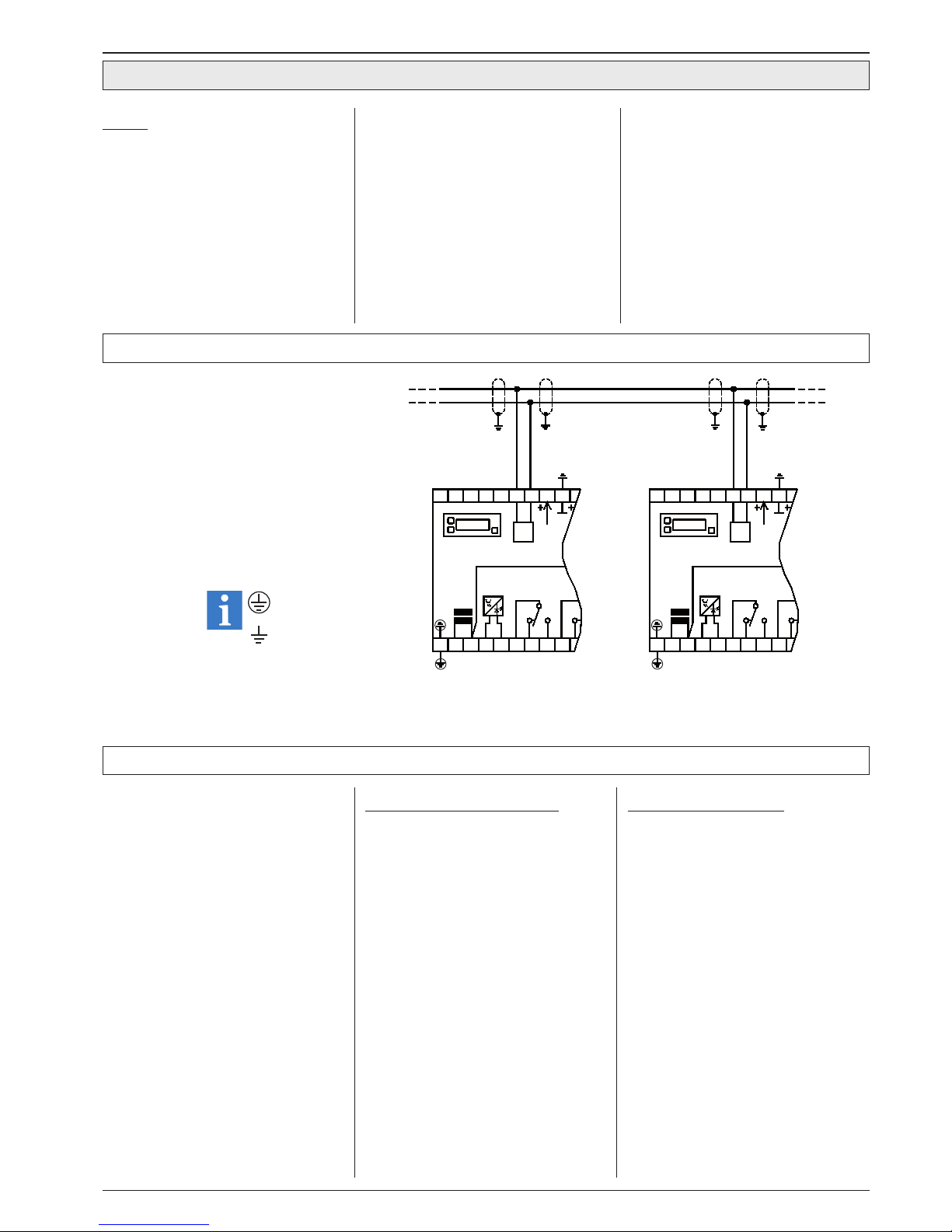
Technical Manual Cold Storage Controller EVP 3150-1 and EVP 3150-2 Page 15
Networking of controllers via E-LINK
The EVP-controller can be used as intelligent
cold storage controller in co-operation with the
compound control system VPR.
In this case, the VPR central processing unit
monitors the EVP.
When the EVP's are connected to the compound
controller, each one needs an individual address
("P90", Mode Page)
For the EVP's there is a possibility of assigning
each controller to a certain compound ("P01",
Mode Page). This enables the VPR to transmit
specific information to the cold storage controllers assigned to the compound where a failure
occurs. Additionally, the information exchange
allows different optmizing methods for suction and
condensing control.
More detailed information you will find in the technical manuals of the VPR compound systems.
Behavior in case of a compound failure
If an EVP is assigned to a certain compound and a
disturbance occurs, the unit responds as follows:
● The solenoid valves close
● The fan switches off
● A defrost will be terminated. A new defrost
period is only possible after the compound
problem is solved.
To see if this function is released, look at
"L41" (Actual Values Page).
"0" = solenoid valve closed
"1" = solenoid valve open
"oFF" = solenoid valve closed via interface
The EVP can be networked together with other
ELREHA control devices via an RS-485-2-wire
databus, which enables up to 78 controllers to
communicate. For communication, the E-LINK
transmission protocol is used.
Each controller in a network has its individual
address ("P90", Mode Page). The data transmission
rate is factory set to "Aut(o)", this means that it will
be identified automatically. If necessary, the rate can
also be set manually ("P91", Mode Page).
This address is necessary for selecting the right
controller when a data package is transmitted on
the network bus. If the controller is used outside a
network, these parameters are of no importance.
Remote control at Frontend Systems
EVP controllers can be operated remotely via
interface when they are connected to Frontend
Systems such as SMZ or VPR.
In this case, the Frontend System shows the EVP's
display contents and the keys of the frontend work
as if they where the keys of the EVP.
Wiring of data lines
The scheme beside shows briefly, how dataline
wiring of several controllers is made. At each controller, the shield has to be connected to the nearest
ground terminal. Also the ground connector of the
controller and terminal #28 must be connected to
the nearest ground terminal.
This will assure good interference suppression,
even for long datalines between the controllers.
Communication with the VPR Compound Controller System
Configuration / Service via PC
The controller can be linked to a PC via its RS-485
interface. By using the PC-software „CoolvisionMES“, parameters can be changed, they can be
saved to the hard disk (download) and can be send
to other controllers (upload).
To do this, the PC must be equipped with an RS485 interface (internal card or an converter of the
SSC-series).
Data transmission disturbances
If the controller gets no new information from
the VPR, it continues working with the current
settings.
If there was an order from the VPR to close the
solenoid valves and a technical defect interupts
the data transmission for more than 30 minutes,
the EVP ignores this order and starts working
normally.
When data transmission is restored, the EVP will
work again immediately according to the commands
of the VPR.
Note
Protective Earth
Earth
analog out
N
L
N
L
1 2 3 4 5
OK/ DI 2
Netz
Mai ns
976 8
Rela is K1
20 2421 22 23 28
NDO
DO
RS
485
262 5 27
analog out
Rela is K1
6
N
L
N
L
21 3 4 5
Netz
Mai ns
OK/ DI 2
97 8
25212 0
NDO
2422 23
DO
RS
485
2826 27
relay k1 relay k1
Page 16
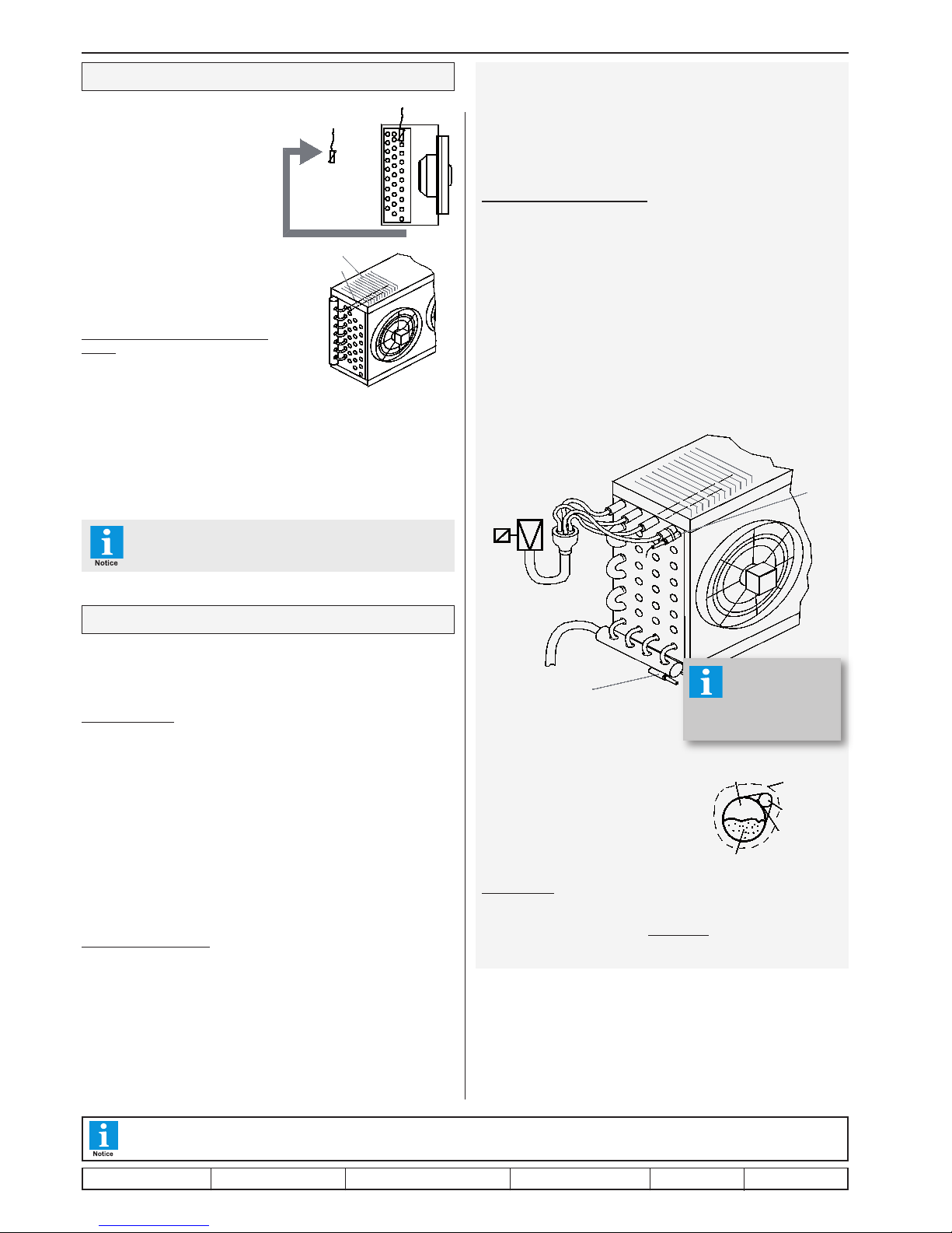
Technical Manual Cold Storage Controller EVP 3150-1 and EVP 3150-2Page 16
Installation / Start-Up
Upon applying voltage to the controller, after a few seconds the display
shows the parameter which is selected as permanent display or an actual
error code.
Start-up sequence
• Assign inputs/outputs to functions (see example on page 3)
• Select type of used temperature sensors ("P35", Mode Page),
use TF 501 types for EEx-valves.
• Correct the displayed temperature values if necessary
("P31"-"P34", Mode Page).
• Set date and time ("P81"-"P87", Mode Page)
• Set defrost mode ("d02", Defrost Page)
• Set fan mode "d01" and "P02"
• Set cooling mode "P03" (Mode Page)
• See page 9 for parameterization of the pressure transmitter inputs
These are the most important steps for the basic configuration of the controller.
Upon that, adapt the other parameters like temperature setpoint, hysteresis,
delay times.... Refer to the previous chapters in this manual.
Start-up in a data network
• Set the address of the controller ("P90", Mode Page)
• Upload parameters from PC to controller
The EVP offers several status messages, which enables you to check the
states of inputs and outputs:
• "
L50", value of the analogue output
• "
L60", state of the digital inputs DI1 and DI2
• "
L61", state of the relays
Sensor positions for EEx-Valve Control,
Pressure Transmitter / Temperature Sensor Method
The pressure transmitter must be mounted at the suction pipe, at a position
where no pressure decrease can affect the measuring. The best place is
close to the evaporator. If there are several evaporators, select a position
from where the distance to all evaporators is as short as possible.
Selection of Pressure Transmitter
To detect a pressure transmitter malfunction, the signal voltage input is
scalable. So you can use e.g. transmitters with an 2...10V output which
makes it easier to recognize a malfunction.
Number of controllers working with the same pressure
transmitter
The input resistance of the pressure transmitter input is 80 kOhm. Several
inputs can be connected in parallel, but the resulting resistance must not
fall below the minimum specifications of the used pressure transmitter.
In practise, up to 10 controllers mostly work trouble-free.
Sensor positions for EEx-Valve control,
Temperature Sensors Method
* = alternative positions for Outlet-Sensor
Please care for a good isolation
by foamed material, so that none
of the sensors get contact with
the airflow.
Pipe mounting
Most expedient is it to use cable fixers, some thermal conduction silico-
ne cares for a good thermal flow.
Metallic fixers with high mass are not qualified.
Sensor Positions
Sensor positions are not critical in standard applications. The control sensor
or alarm sensor has to be fixed behind
the evaporator (air-inlet) or at a representative place in the chamber, but not
in the air outlet.
The second sensor (defrost term-inati-
on sensor, evaporator sensor) should
be assembled in the contact pipe or
within the fins of the evaporator. A good
thermal exchange to the fins is important.
It should be placed at the position where
the ice remains the longest time while
a defrost cycle.
Sensors for intelligent (adaptive)
defrost
To detect icing the EVP doesn't need
additional sensors. The control sensor
and the defrost (evap.) sensor are sufficient. Please note that the emergency
defrost mode is not able to prevent iceclusters or slow glacieration in case of a
incorrect sensor position. If ice-clusters
appear, the defrost sensor must be
placed at this position.
After start-up, Please check the position of the
evaporator sensors accurately!!
This manual, which is part of the product, has been set up with care and our best knowledge, but mistakes are still possible. Technical details
can be changed without notice, especially the software. Please note that the described functions are only valid for units containing the software
with the version-number shown on page 1 of this manual. Units with an other version number may work a little bit different.
evap sensor
control sensor
airflow
fins
contactpipe
*
*
*
pipe
distributor
EEx-valve
outlet
sensor
inlet
sensor
foam Isolation
sensor
thermal
conduction
silicone
liquid
gaseous
refrigerant in
evaporator pipe
For more information about
Electronic Expansion Valves
see page 9 !
set up: 26.6.17, tkd/jr checked: 26.6.17, ek/jk approved: 26.6.17, mv/sha transl.(E): ...................... transl()................ corr.
 Loading...