

ELREHA EGS CO2 SET, EGS CO2 SET V2 User Manual

ELEKTRONISCHE REGELUNGEN GMBH
Manual 5311555-00/00ge/00
2019-08-29, tkd/wr
EGS CO2 SET
EGS CO2 SET V2
Kurzbeschreibung
Das Gaswarngerät EGS AE ist speziell
zum Melden von Lecks in Kälteanlagen
vorgesehen. Mit einem speziellen
externen Sensormodul können Lecks
von Kältemittel- oder CO2-Anlagen
erfasst werden.
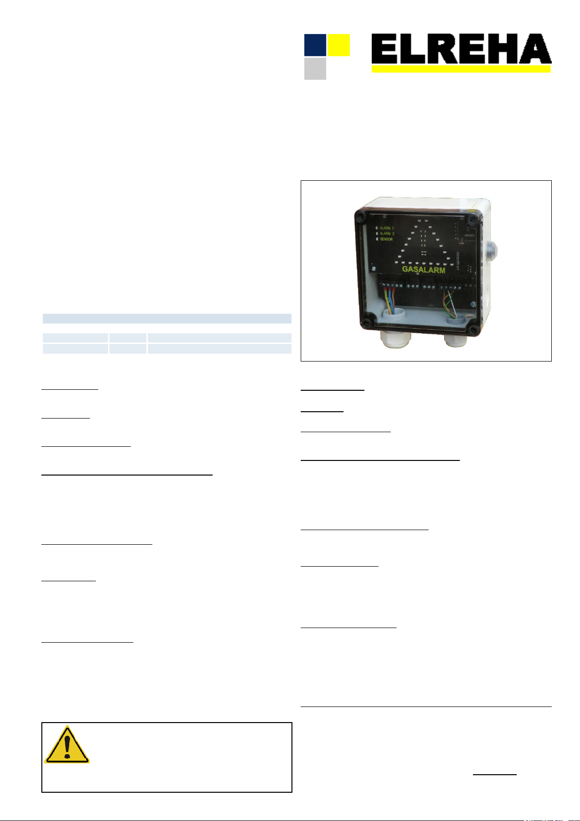
Wird ein Gas detektiert, dann wird
dies über einen großen, dreieckigen
LED-Alarm, akustisch und über zwei
Alarmrelais weitergemeldet.
Zusätzlich ist es möglich, an die
Auswerteinheit (AE) einen Reset/TestTaster anzuschließen.
Die in der Sensoreinheit (SE) befindliche Hupe muss, zur Alarmierung, an
die Auswerteeinheit (AE) angeschlossen werden.
Mit Relais 1 kann z.B. eine Absaugvorichtung eingeschaltet werden, mit
Relais 2 kann die Anlage abgeschaltet
oder eine Störmeldung weitergeben
werden.
Nachdem die Konzentration wieder
gesunken ist, werden Relais und LED's
zurückgesetzt. Der Signaleingang für
das Sensorelement wird intern überwacht, liegen die Signale außerhalb
des Bereichs, wird ein Fehler angezeigt (LED "Sensor").
Anschließbare Sensoren / Connectable Sensors
Brief Description
The EGS AE utilizes a special external
sensor module to effectively detect
refrigerant or CO2 leaks in cooling
facilities.
If a gas concentration above the
defined limit is detected, a large
triangular LED alarm is activated, along
with an audible alarm and up to two
alarm relays.
This allows flexible alarm signaling
and forwarding.
After the gas concentration has
dropped down to normal conditions,
the relays and the LED's are reset.
The signal input of the external gas
sensor element is monitored
internally.
If the signal is out of range, LED
'Sensor' indicates a failure.
ELEKTRONISCHE REGELUNGEN GMBH
Betriebsanleitung 5311554-00/02ge/01
2018-05-30 tkd/jr
Kältemittel-Leckwarner
Refrigerant Leak Detector
EGS AE
EGS CO2 SE 22V DC Signal 4-20mA
Funktionen
Sensoranschluss
Es können externe Sensoren mit einem 4-20mA Ausgangssignal verwendet
werden.
Alarmgrenzen
Alarmgrenzen können mit DIP-Schaltern festgelegt werden (siehe Anschlussbild).
Anzeige im Normalzustand
Im Normalzustand zeigt die EGS Auswerteinheit den einwandfreien Betrieb
über die 4 unteren LEDs der AMS-Anzeige an
Alarmmeldung bei Überschreiten von Alarmgrenzen
Wird eine Alarmgrenze überschritten, wird dies über die blinkende Dreiecks-LED
Anzeige (TAS) und die jeweilige Alarm LED angezeigt. Gleichzeitig löst (pulst)
der interne Warnsummer der Auswerteeinheit und falls der Warnsummer in der
Sensoreinheit mit der Auswerteeinheit verbunden ist, löst (pulst) auch dieser
aus. Die entsprechenden Alarmrelais fallen ab. Die Dreiecks-LED, die Alarm
LED und die Warnsummer gehen automatisch aus, wenn die Alarmgrenzen
unterschritten werden.
Alarmmeldung bei Sensorstörung
Bei einer Sensorstörung blinken sowohl die Dreiecks-LED (TAS), die Alarm 1-,
Alarm 2-, die Sensor LED und die Warnsummer werden aktiviert. Nachdem die
Störung behoben ist, zeigen die LEDs den aktuellen Status wieder an.
Alarmquittierung
Sowohl mit dem Quittiertaster auf der rechten Seite des Gehäuses der Auswerteeinheit, als auch mit dem extern anschließbaren Quittiertaster können die
Warnsummer zurückgesetzt werden. Nach dem Quittieren blinkt die DreiecksLED (TAS) weiter und die LED Anzeige AMS ist permanent an. Sollte die 2.
Alarmgrenze überschritten werden wird die Alarmmeldung, wie beschrieben,
erneut ausgelöst und kann ebenfalls quittiert werden.
LED und Warnsummer Test
Sowohl mit dem Quittiertaster auf der rechten Seite des Gehäuses der Auswerteeinheit, als auch mit dem extern anschließbaren Quittiertaster kann eine
Funktionsprüfung aller LEDs und der Warnsummer erfolgen.
- Die rote Dreiecks-LED Anzeige (TAS) wird eingeschaltet
- Die grüne LED Ausrufezeichen (AMS) wird eingeschaltet
- Die Alarm 1-, Alarm 2- und Sensor LED wird eingeschaltet
- Der interne Warnsummer wird eingeschaltet
- und falls angeschlossen der externe Warnsummer wird eingeschaltet
Bitte Sicherheits- und
Betriebshinweise beachten!
Please note Safety and
Operating Instructions !
Functions
Sensor Connection
An external sensor with a 4-20mA output signal can be used.
Alarm Limits
Alarm limits can be set by DIP-switches (see wiring diagram).
Display in normal operation
In normal operation, the EGS unit indicates proper operation by the 4 lower
LEDs of the AMS display.
Alarm message when alarm limits are exceeded
If an alarm limit is exceeded, this is indicated by the flashing triangular LED
display (TAS) and the respective alarm LED.
The internal warning buzzer of the evaluation unit is activated (pulsed) and
also the buzzer in the sensor unit is activated (pulsed) if connected.
The corresponding alarm relays are switched off. The triangle LED, the
alarm LED and the warning buzzer are reset automatically when the gas
concentration returns to normal conditions.
Alarm message in case of sensor fault
In the event of a sensor fault, both the triangle LED (TAS), the alarm 1-,
alarm 2-, the sensor LED and the warning buzzer are activated. After the fault
has been rectified, the LEDs will indicated the current status again.
Alarm acknowledgment
The warning buzzers can be reset by either the internal acknowledgment button
located on the right side of the evaluation unit or by an externally connected
acknowledgment button. After acknowledgment, the triangle LED (TAS) continues flashing and the AMS LED indicator is permanently on. If the 2nd alarm
limit is exceeded, the alarm message is triggered again (similar to 1st alarm)
and can also be acknowledged.
LED and warning buzzer test
A function test of all LEDs and the warning buzzer can be activated by either
the internal acknowledgement button of the evaluation unit or by an externally
connected button.
- The red triangular LED indicator (TAS) is switched on
- The green LED exclamation mark (AMS) is switched on
- The Alarm 1-, Alarm 2- and Sensor LEDs are switched on
- The internal buzzer is switched on
- If connected, the external buzzer is switched on
Vor Inbetriebnahme diese Betriebsanleitung sorgfältig lesen! Entstehen durch Nichtbeachtung
Schäden, erlöschen die Garantieansprüche. Diese Dokumentation würde mit größter Sorgfalt erstellt.
Dennoch können wir für die vollständige Richtigkeit keine Garantie übernehmen.
Please read these instructions carefully before applying power. Your attention is drawn to the
fact that the warranty is subject to the application of power sources that are within the limits
specified in this manual. Repairs or modifications made by anyone other than ELREHA will also
void the product warranty. This documentation was compiled with utmost care, however, we
cannot guarantee for its correctnesss in every respect.
D-68766 Hockenheim, Germany, Schwetzinger Str. 103
Telefon (+49)(0) 6205/2009-0 - Fax (+49)(0) 6205/2009-39 - sales@elreha.de
ELREHA GmbH
Seite/Page 2 Betriebsanleitung/Manual EGS AE
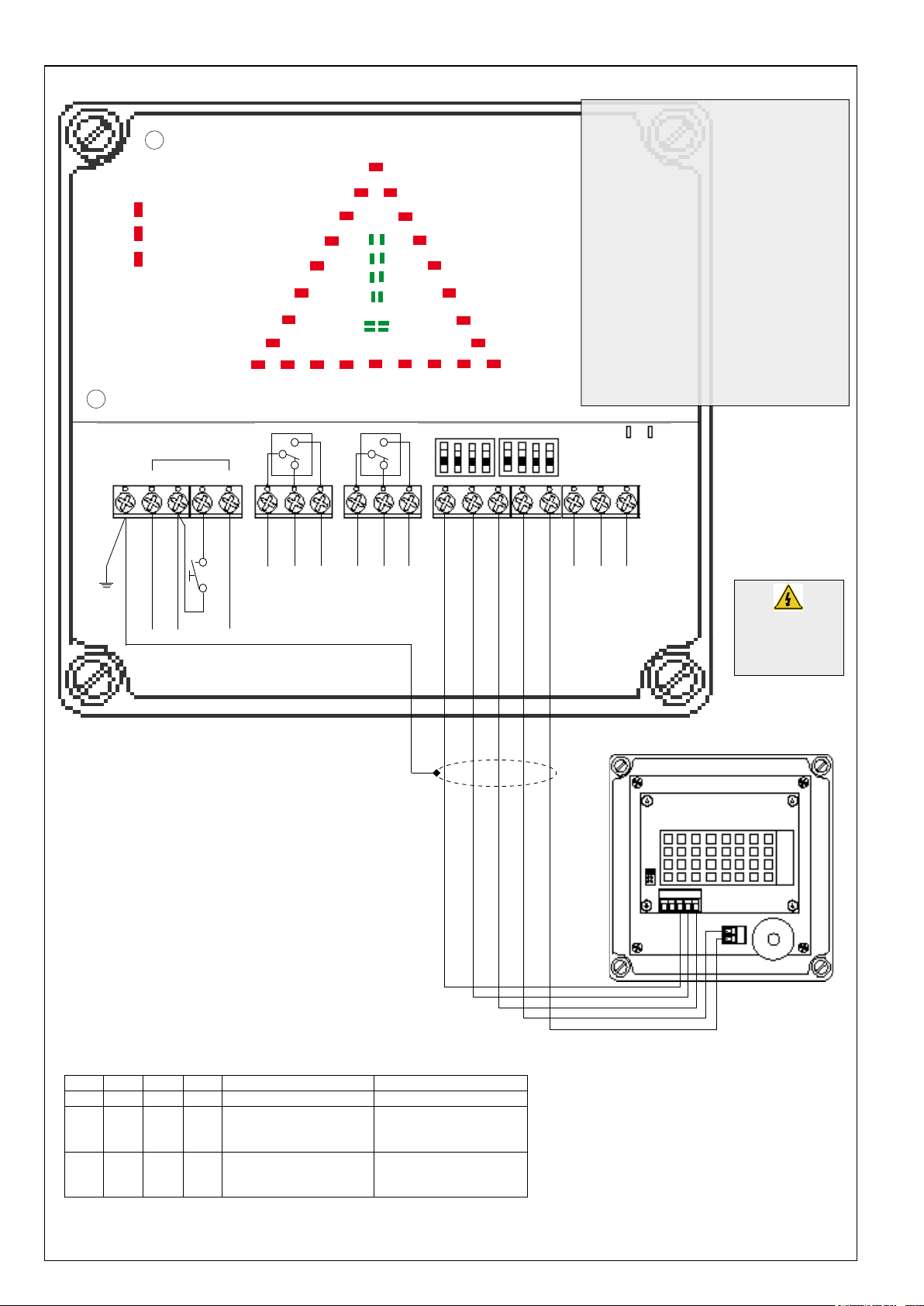
Anschlussklemmen und DIP-Schalter / Positions of screw terminals and DIP switches
LED-Meldungen
- ALARM 1 ein = Grenzwert überschritten
- ALARM 2 ein = Grenzwert überschritten
- SENSOR ein = Sensor nicht oder fehlerhalft
angeschlossen oder defekt
- Rote Dreiecksanzeige (TAS) ein
= Alarmmeldung
ALARM 1
ALARM 2
SENSOR
(AMS)
- Grünes Ausrufezeichen (AMS) komplett ein
= Alarmmeldung per Taste quittiert aber noch
vorhanden
- Ausrufezeichen (AMS) nur die 4 unteren LEDs
= Normalbetrieb, kein Alarm vorhanden
LED Information
- ALARM 1 on = limit exceeded
- ALARM 2 on = limit exceeded
- SENSOR on = sensor not or incorrect
(TAS)
connected or defect
- Red triangular LED indicator (TAS) on
= Alarm message
- Green exclamation mark (AMS) fully turned on
= Alarm message reset by button but still present
- Exclamation mark (AMS) only the 4 lower LEDs
GASALARM
= Normal operation, no alarm present
* *
COM
Alarm 1 Alarm 2
Ext. Quit L [230V]
Netz/mains L 230V
Netz/mains N 230V
Wenn ein externer Taster angeschlossen wird,
*
dann Klemme 2 + 5 brücken !!
When an external button is connected,
*
then bridge the clamp 2 + 5 !!
Ext. Quit N [230V]
NC
NO
COM
DIP 1 2 3 4 5 6 7 8
1
0
NO
NC
Sensor GND
Sensor I [4-20mA]
Hupe/buzzer [GND]
Sensor V+ [22V DC]
LED System
läuft / running
GND
NDO
Hupe/buzzer [+12V]
LED
Communication
DO
Sicherheitshinweise
beachten!
Note Safety
Instructions !
EGS CO2 SE
DIP-Schalter / Switches
DIP 1 DIP 2 DIP 3 DIP 4 Alarm 1 / [ppm] / Relais 1 Alarm 2 / [ppm] / Relais 2
0 0 0 0 Kein Alarm / No Alarm Kein Alarm / No Alarm
1 0 1 0 19000 ppm Alarm ein/on
18000 ppm Alarm aus/off
standard / default
0 1 0 1 5000 ppm Alarm ein/on
4000 ppm Alarm aus/off
30000 ppm Alarm ein/on
29000 ppm Alarm aus/off
standard / default
15000 ppm Alarm ein/on
14000 ppm Alarm aus/off
GND I V+
Buzzer
+12V
 Loading...