

ELREHA BM Series, BMR 3001 Brief Instruction
ELEKTRONISCHE REGELUNGEN GMBH
D-68766 Hockenheim
Schwetzinger Str. 103
Telefon 0 62 05 / 2009-0
Telefax 0 62 05 / 2009-39
email team@elreha.de
internet www.elreha.de
Kurzanleitung
Brief Instruction
Bitte Sicherheits-
hinweise beachten!
Allgemein
Die Erweiterungsmodule (I/O-Module) im Normschienengehäuse der Serie BMR dienen zur Steuerung von Anlagenkomponenten oder der Weitergabe von Störmeldungen. Die Module werden über einen Datenbus
mit einer zentralen Steuerung (z.B. dem VPR 5140) vernetzt und von
dort aus gesteuert. Alle elektrischen Verbindungen sind steckbar.
Brief Description
The I/O-Modules of the series BMR for DIN-rail mounting are able to
control plant components or to forward error messages. The modules
are connected to a Central Unit via databus (e.g. to the VPR 5140).
All terminals are pluggable for easy electrical connection.
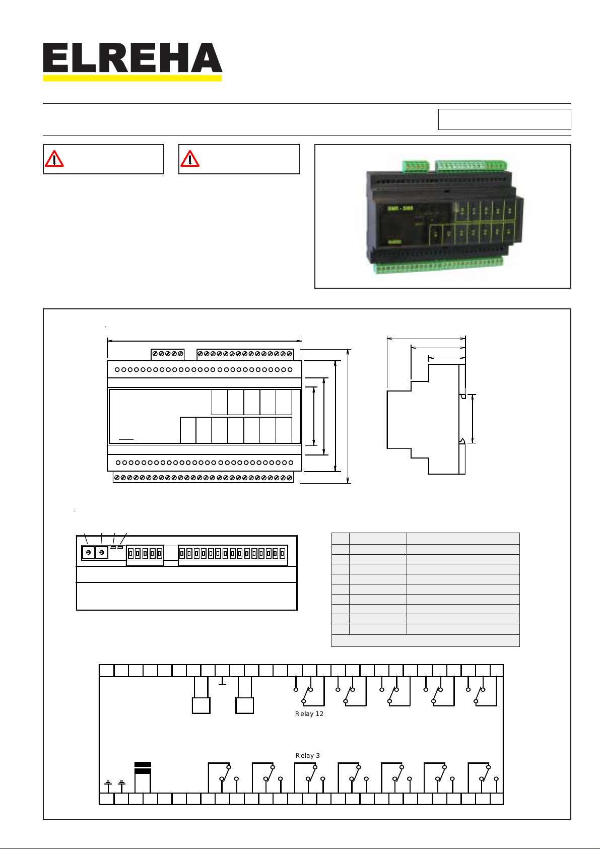
Abmessungen / Dimensions
BMR - 3000
ELREHA
I/O Module BMR 3001
Please always note
Safety Instructions!
153 (6.02)
1
2
1
K
1
2
K
3
K
K
0
1
1
K
K
5
4
K
K
8
9
K
K
7
6
K
K
No. 5311256-00/01
59 (2.32)
39 (1.54)
26 (1.02)
)
)
)
)
5
8
.
1
(
7
4
9
6
8
4
6
4
.
.
.
4
3
2
(
(
(
4
3
3
1
9
6
1
)
8
3
.
1
(
5
3
Adress-Schalter / Position of address switches Adresseinstellung / Address setting
adr
adr
LED
SW 2
SW 1
Netz
Mains
LED
Com
Setting an databus-address
adrSW 2 adrSW 1
8
8
7
7
9
9
6
6
0
0
5
5
1
1
4
4
2
2
3
3
00 0
10 1
20 2
30 3
40 4
etc....
10 1 0
11 1 1
12 1 2
Elektrische Anschlüsse / Electrical Connection
35
O
O
D
D
N
RS
485
BMR 3001
Netz
PE
Mains
Ground
N
4L321
Relay 1 Relay 2
765
39
383736 42
L
H
CAN
1098 14
1312
11
Relay 12
Relay 3
and so on. The highest usable address is '77'
4643 4544 494847
Relay 4
1815 1716 212019
Relay 10Relay 11
Relay 5
Relay 9 Relay 8
Relay 6 Relay 7
22
23 24
53525150 565554
25
2826 27
Seite 2
Betriebsanleitung / Manual I/O-Modules Series BMx
Busanbindung / Adresseinstellung
Das BMR wird über den RS-485-Anschluß mit dem ICOM-Datenbus der
Zentraleinheit verbunden. Das Modul erhält eine individuelle Adresse, die an
der Oberseite des Gehäuses mittels zweier Rastschalter eingestellt wird.
Die rote Status-LED "Netz" zeigt den Betriebszustand des Moduls, die LED
"Com" eine Kommunikation mit der Zentraleinheit an.
Schaltzustände
Der Schaltzustand jedes Relais wird mit je einer LED angezeigt (LED an =
Relais angezogen), die durch die transparente Abdeckung scheint.
Technische Daten
Betriebsspannung / Leistungsaufnahme ................ 230V 50Hz / ca. 5VA
Umgebungstemperatur .........................................0...+50°C (32...122°F)
Max. Luftfeuchte....................................... 85% r.F., nicht kondensierend
Schaltausgänge ....... 12x Wechsler, potentialfrei, 8A cos phi=1/250VAC
Schaltzustandsanzeige .....................................................................LED
Schnittstelle..................................................................... RS 485 (ICOM)
Gehäuse ....................Kunststoffgehäuse mit Klarsichtabdeckung, IP 30
Inbetriebnahme
! Gerät mechanisch montieren
! Datenbusverbindung auflegen, dabei auf Polung achten!
! Korrekte Netzwerkadresse mit den Rastschaltern an der
Oberseite des Gehäuses einstellen. Eine Netzwerkadresse darf auf
diesem Bus nur einmal vergeben werden!
! Elektrischer Anschluss der Anlagenkomponenten erfolgt nach
dem für oder an der Zentraleinheit erstellten Anschlussplan.
! Betriebsspannung einschalten
Databus Connection / Address Setting
The BMR is connected to the ICOM-databus of the central unit by its RS-485interface. The module gets an individual address, which can be set by two
incremental switches at the upper side of the housing. The red LED "Mains"
indicates the readiness for operation, the LED "Com" indicates communication
with the central unit.
Switching States
The status of each relay is indicated by a LED (LED on = relay activated),
which is visible through the transparent cover.
Technical Data
Supply Voltage / Power Consumption.....................230V 50Hz / ca. 5VA
Ambient Temperature ........................................... 0...+50°C (32...122°F)
Max. Ambient Humidity .................................... 85% r.h., not condensing
Switching Outputs ........ 12x SPDT, potential free, 8A cos phi=1/250VAC
Relay Indicators ................................................................................LED
Interface .......................................................................... RS 485 (ICOM)
Housing .............................................. ABS with transparent cover, IP 30
Start-up
! Mount unit to DIN-rail
! Connect databus, note polarity!
! Set correct network address with the incremental switches at the
top of the housing.
Never use a network address twice on this databus!
! The electrical connection of the plant components must be done
depending on the plan designed for or at the central unit.
! Switch power on
ANSCHLUSS- UND SICHERHEITSHINWEISE
Bitte vor dem Anschluss lesen
• Die Installation und Inbetriebnahme des Gerätes darf
nur durch eine Elektrofachkraft oder durch eine
Person unter der Aufsicht einer Elektrofachkraft
durchgeführt werden.
• Das Gerät darf nur für den beschriebenen Einsatzzweck
verwendet werden.
• Bitte beachten Sie die einschlägigen örtlichen
Sicherheitsvorschriften.
• Bitte prüfen sie vor dem Einsatz des Reglers dessen
Grenzen und dessen Anwendung:
Entspricht die Spannungsversorgung dem auf dem
Gerät aufgedruckten Wert ?
Stimmen die vorgeschriebenen Umgebungsbedingungen (Temperatur- bzw. Feuchtegrenzen) ?
Bei Nichteinhalten können Fehlfunktionen nicht ausgeschlossen werden.
• Gerät bei der Montage sicher vom Stromnetz
getrennt halten !
• Betreiben Sie das Gerät niemals ohne Gehäuse
(Gefahr eines Stromschlags).
• Die PE-Klemme des Gerätes muss auf PE gelegt
werden !
• Beachten Sie die maximale Belastung der RelaisKontakte (siehe technische Daten).
• Vermeiden Sie den Einbau in unmittelbarer Nähe von
großen Schützen (starke Störeinstrahlung möglich).
• Bitte beachten Sie bei der Installation von Datenleitungen
die entsprechenden Anforderungen.
CONNECTION & SAFETY INFORMATION
Please read before Start-up
• Limit of Application: This product is not designed nor
manufactured for use in equipment or systems that are
intended to be used under such circumstances that may
affect human life. For applications requiring extremely high
reliability, please contact the manufacturer first.
• Electrical installation and putting into service must be
done from authorized personnel.
• Please note the local safety instructions !
• Before installation: Check the limits of the controller and
your application. Before starting up we recommend you to
read the following instructions for use, since only by doing
so you can avoid damage or malfunction and you will
benefit all the advantages offered by this product.
• During installation and wiring never work when the
electricity is not cut-off !
• Never operate unit without housing.
• Mounting the controller close to power relays is
unfavourable in case of the electro-magnetic interference.
• Before applying voltage to the controller:
Make sure that all wiring has been made in accordance
with the wiring diagram in this manual. Check, if the supply
voltage corresponds to the value printed on the type label.
• Connect ‘PE’ terminal carefully to ground because otherwise
the operation of the internal noise filter is disabled.
• Respect the environmental limits for temperature and
humidity. Outside these limits malfunctions may occur.
• Take care that the wiring of interface lines meets the
requirements
(copy)
We state the following: When operated in accordance with the technical manual, the criteria have been met that are outlined in the guidelines of the council for alignment of statutory
orders of the member states on electro-magnetic consistency (89/336/EWG) and the Low Voltage Directive (73/23/EWG) as amended by (93/68/EWG). This declaration is valid
for those products covered by the technical manual which itself is part of the declaration. To meet the requirements, the currently valid versions of the relevant standards have
been used. This statement is made from the manufacturer / importer by:
ELREHA Elektronische Regelungen GmbH Werner Roemer, Technical Director
D-68766 Hockenheim
(name / adress) Hockenheim.............16.06.2005......................................................
Diese Anleitung haben wir mit Sorgfalt erstellt, Fehler können wir aber nie ganz ausschließen. Änderungen der Konstruktion behalten wir uns vor.
Dokument erstellt: 15.11.05/tkd/jr geprüft: 15.11.05/ek/jk freigegeben: 15.12.05/mv/sha
EG-Statement of Conformity
city date sign
 Loading...