

Page 1

The MSP430 Flash Programmer
Multi-FPA API-DLL User’s Guide
for the USB-MSP430-FPA and MSP-FET430UIF Adapters
Software version 4.5
PM010A05 Rev.22
April-05-2010
Elprotronic Inc.
Page 2

Elprotronic Inc.
16 Crossroads Drive
Richmond Hill,
Ontario, L4E-5C9
CANADA
Web site: www.elprotronic.com
E-mail: info@elprotronic.com
Fax: 905-780-2414
Voice: 905-780-5789
Copyright © Elprotronic Inc. All rights reserved.
Disclaimer:
No part of this document may be reproduced without the prior written consent of Elprotronic Inc.
The information in this document is subject to change without notice and does not represent a
commitment on any part of Elprotronic Inc. While the information contained herein is assumed to
be accurate, Elprotronic Inc. assumes no responsibility for any errors or omissions.
In no event shall Elprotronic Inc, its employees or authors of this document be liable for special,
direct, indirect, or consequential damage, losses, costs, charges, claims, demands, claims for lost
profits, fees, or expenses of any nature or kind.
The software described in this document is furnished under a licence and may only be used or copied
in accordance with the terms of such a licence.
Disclaimer of warranties: You agree that Elprotronic Inc. has made no express warranties to You
regarding the software, hardware, firmware and related documentation. The software, hardware,
firmware and related documentation being provided to You “AS IS” without warranty or support
of any kind. Elprotronic Inc. disclaims all warranties with regard to the software, express or implied,
including, without limitation, any implied warranties of fitness for a particular purpose,
merchantability, merchantable quality or noninfringement of third-party rights.
Limit of liability: In no event will Elprotronic Inc. be liable to you for any loss of use, interruption
of business, or any direct, indirect, special incidental or consequential damages of any kind
(including lost profits) regardless of the form of action whether in contract, tort (including
negligence), strict product liability or otherwise, even if Elprotronic Inc. has been advised of the
possibility of such damages.
2
Page 3

END USER LICENSE AGREEMENT
PLEASE READ THIS DOCUMENT CAREFULLY BEFORE USING THE SOFTWARE AND
THE ASSOCIATED HARDWARE. ELPROTRONIC INC. AND/OR ITS SUBSIDIARIES
(“ELPROTRONIC”) IS WILLING TO LICENSE THE SOFTWARE TO YOU AS AN
INDIVIDUAL, THE COMPANY, OR LEGAL ENTITY THAT WILL BE USING THE
SOFTWARE (REFERENCED BELOW AS “YOU” OR “YOUR”) ONLY ON THE CONDITION
THAT YOU AGREE TO ALL TERMS OF THIS LICENSE AGREEMENT. THIS IS A LEGAL
AND ENFORCABLE CONTRACT BETWEEN YOU AND ELPROTRONIC. BY OPENING THIS
PACKAGE, BREAKING THE SEAL, CLICKING “I AGREE” BUTTON OR OTHERWISE
INDICATING ASSENT ELECTRONICALLY, OR LOADING THE SOFTWARE YOU AGREE
TO THE TERMS AND CONDITIONS OF THIS AGREEMENT. IF YOU DO NOT AGREE TO
THESE TERMS AND CONDITIONS, CLICK ON THE “I DO NOT AGREE” BUTTON OR
OTHERWISE INDICATE REFUSAL, MAKE NO FURTHER USE OF THE FULL PRODUCT
AND RETURN IT WITH THE PROOF OF PURCHASE TO THE DEALER FROM WHOM IT
WAS ACQUIRED WITHIN THIRTY (30) DAYS OF PURCHASE AND YOUR MONEY WILL
BE REFUNDED.
1. License.
The software, firmware and related documentation (collectively the “Product”) is the property of
Elprotronic or its licensors and is protected by copyright law. While Elprotronic continues to own
the Product, You will have certain rights to use the Product after Your acceptance of this license.
This license governs any releases, revisions, or enhancements to the Product that Elprotronic may
furnish to You. Your rights and obligations with respect to the use of this Product are as follows:
YOU MAY:
A. use this Product on many computers;
B. make one copy of the software for archival purposes, or copy the software onto the hard disk
of Your computer and retain the original for archival purposes;
C. use the software on a network
YOU MAY NOT:
A. sublicense, reverse engineer, decompile, disassemble, modify, translate, make any attempt
to discover the Source Code of the Product; or create derivative works from the Product;
B. redistribute, in whole or in part, any part of the software component of this Product;
3
Page 4

C. use this software with a programming adapter (hardware) that is not a product of
Elprotronic Inc or Texas Instruments Inc.
2. Copyright
All rights, title, and copyrights in and to the Product and any copies of the Product are owned by
Elprotronic. The Product is protected by copyright laws and international treaty provisions.
Therefore, you must treat the Product like any other copyrighted material.
3. Limitation of liability.
In no event shall Elprotronic be liable to you for any loss of use, interruption of business, or any
direct, indirect, special, incidental or consequential damages of any kind (including lost profits)
regardless of the form of action whether in contract, tort (including negligence), strict product
liability or otherwise, even if Elprotronic has been advised of the possibility of such damages.
4. DISCLAIMER OF WARRANTIES.
You agree that Elprotronic has made no express warranties to You regarding the software, hardware,
firmware and related documentation. The software, hardware, firmware and related documentation
being provided to You “AS IS” without warranty or support of any kind. Elprotronic disclaims all
warranties with regard to the software and hardware, express or implied, including, without
limitation, any implied warranties of fitness for a particular purpose, merchantability, merchantable
quality or noninfringement of third-party rights.
4
Page 5
This device complies with Part 15 of the FCC Rules.
Operation is subject to the following two conditions:
(1) this device may not cause harmful interference and
(2) this device must accept any interference received,
including interference that may cause undesired
operation.
NOTE: This equipment has been tested and found to comply with the limits for a Class B digital devices,
pursuant to Part 15 of the FCC Rules. These limits are designed to provide reasonable protection against harmful
interference in a residential installation. This equipment generates, uses, and can radiate radio frequency energy
and, if not installed and used in accordance with the instruction manual, may cause harmful interference to
radio communications. However, there is no guarantee that interference will not occur in a particular
installation. If this equipment does cause harmful interference to radio or television reception, which can be
determined by turning the equipment off and on, the user is encouraged to try to correct the interference by one
of more of the following measures:
* Reorient or relocate the receiving antenna
* Increase the separation between the equipment and receiver
* Connect the equipment into an outlet on a circuit different from that to which the receiver is connected
* Consult the dealer or an experienced radio/TV technician for help.
Warning: Changes or modifications not expressly approved by Elprotronic Inc. could void the user’s authority
to operate the equipment.
This Class B digital apparatus meets all requirements of the Canadian
Interference-Causing Equipment Regulations.
Cet appereil numerique de la classe B respecte toutes les exigences du
Reglement sur le material brouilleur du Canada.
5
Page 6

Table of Contents
1. Introduction . . . . . . . . . . . . . . . . . . . . . . . . . . . . . . . . . . . . . . . . . . . . . . . . . . . . . . . . . . . . . 9
1.1 Using TI’s MSP-FET430UIF adapter . . . . . . . . . . . . . . . . . . . . . . . . . . . . . . . . . 15
2. Getting Started . . . . . . . . . . . . . . . . . . . . . . . . . . . . . . . . . . . . . . . . . . . . . . . . . . . . . . . . . . 17
2.1 Self Test Program . . . . . . . . . . . . . . . . . . . . . . . . . . . . . . . . . . . . . . . . . . . . . . . . 17
2.2 MyMSP430Prg Projects . . . . . . . . . . . . . . . . . . . . . . . . . . . . . . . . . . . . . . . . . . . . 19
2.3 API DLL Demo Program . . . . . . . . . . . . . . . . . . . . . . . . . . . . . . . . . . . . . . . . . . . 23
3. Example with API DLL . . . . . . . . . . . . . . . . . . . . . . . . . . . . . . . . . . . . . . . . . . . . . . . . . . . 29
3.1 Example with single FPA . . . . . . . . . . . . . . . . . . . . . . . . . . . . . . . . . . . . . . . . . 29
3.2 Example with Multi-FPA API DLL . . . . . . . . . . . . . . . . . . . . . . . . . . . . . . . . . . 30
4. List of the DLL instructions . . . . . . . . . . . . . . . . . . . . . . . . . . . . . . . . . . . . . . . . . . . . . . . . 33
4.1 Multi-FPA instructions . . . . . . . . . . . . . . . . . . . . . . . . . . . . . . . . . . . . . . . . . . . . 36
F_Trace_ON . . . . . . . . . . . . . . . . . . . . . . . . . . . . . . . . . . . . . . . . . . . . . . . . . . 36
F_Trace_OFF . . . . . . . . . . . . . . . . . . . . . . . . . . . . . . . . . . . . . . . . . . . . . . . . . 36
F_OpenInstances . . . . . . . . . . . . . . . . . . . . . . . . . . . . . . . . . . . . . . . . . . . . . . 37
F_CloseInstances . . . . . . . . . . . . . . . . . . . . . . . . . . . . . . . . . . . . . . . . . . . . . . 37
F_OpenInstancesAndFPAs, F_OpenInstances_AndFPAs . . . . . . . . . . . . . . 38
F_Set_FPA_index . . . . . . . . . . . . . . . . . . . . . . . . . . . . . . . . . . . . . . . . . . . . . 43
F_Get_FPA_index . . . . . . . . . . . . . . . . . . . . . . . . . . . . . . . . . . . . . . . . . . . . . 44
F_Check_FPA_index . . . . . . . . . . . . . . . . . . . . . . . . . . . . . . . . . . . . . . . . . . . 44
F_Disable_FPA_index . . . . . . . . . . . . . . . . . . . . . . . . . . . . . . . . . . . . . . . . . . 45
F_Enable_FPA_index . . . . . . . . . . . . . . . . . . . . . . . . . . . . . . . . . . . . . . . . . . 45
F_LastStatus . . . . . . . . . . . . . . . . . . . . . . . . . . . . . . . . . . . . . . . . . . . . . . . . . . 46
F_Multi_DLLTypeVer . . . . . . . . . . . . . . . . . . . . . . . . . . . . . . . . . . . . . . . . . . 46
F_Get_FPA_SN . . . . . . . . . . . . . . . . . . . . . . . . . . . . . . . . . . . . . . . . . . . . . . . 47
4.2 Generic instructions . . . . . . . . . . . . . . . . . . . . . . . . . . . . . . . . . . . . . . . . . . . . . . . 48
F_Check_FPA_access . . . . . . . . . . . . . . . . . . . . . . . . . . . . . . . . . . . . . . . . . . 48
F_Initialization . . . . . . . . . . . . . . . . . . . . . . . . . . . . . . . . . . . . . . . . . . . . . . . . 49
F_API_DLL_Directory . . . . . . . . . . . . . . . . . . . . . . . . . . . . . . . . . . . . . . . . . 50
F_Close_All . . . . . . . . . . . . . . . . . . . . . . . . . . . . . . . . . . . . . . . . . . . . . . . . . . 51
F_GetSetup . . . . . . . . . . . . . . . . . . . . . . . . . . . . . . . . . . . . . . . . . . . . . . . . . . 52
6
Page 7

F_ConfigSetup . . . . . . . . . . . . . . . . . . . . . . . . . . . . . . . . . . . . . . . . . . . . . . . . 52
F_SetConfig . . . . . . . . . . . . . . . . . . . . . . . . . . . . . . . . . . . . . . . . . . . . . . . . . . 63
F_GetConfig . . . . . . . . . . . . . . . . . . . . . . . . . . . . . . . . . . . . . . . . . . . . . . . . . 64
F_Set_MCU_Name . . . . . . . . . . . . . . . . . . . . . . . . . . . . . . . . . . . . . . . . . . . . 64
F_Get_Device_Info . . . . . . . . . . . . . . . . . . . . . . . . . . . . . . . . . . . . . . . . . . . . 65
F_DispSetup . . . . . . . . . . . . . . . . . . . . . . . . . . . . . . . . . . . . . . . . . . . . . . . . . . 68
F_ReportMessage, F_ReportMessage . . . . . . . . . . . . . . . . . . . . . . . . . . . . . . 68
F_GetReportMessageChar . . . . . . . . . . . . . . . . . . . . . . . . . . . . . . . . . . . . . . . 69
F_DLLTypeVer . . . . . . . . . . . . . . . . . . . . . . . . . . . . . . . . . . . . . . . . . . . . . . . 70
F_ConfigFileLoad, F_Config_FileLoad . . . . . . . . . . . . . . . . . . . . . . . . . . . 71
F_Power_Target . . . . . . . . . . . . . . . . . . . . . . . . . . . . . . . . . . . . . . . . . . . . . . . 72
F_Reset_Target . . . . . . . . . . . . . . . . . . . . . . . . . . . . . . . . . . . . . . . . . . . . . . . 73
F_Get_Targets_Vcc . . . . . . . . . . . . . . . . . . . . . . . . . . . . . . . . . . . . . . . . . . . . 74
F_Set_fpa_io_state . . . . . . . . . . . . . . . . . . . . . . . . . . . . . . . . . . . . . . . . . . . . . 74
4.3 Data Buffers access instructions . . . . . . . . . . . . . . . . . . . . . . . . . . . . . . . . . . . . . 75
F_ReadCodeFile, F_Read_CodeFile . . . . . . . . . . . . . . . . . . . . . . . . . . . . . . 75
F_Get_CodeCS . . . . . . . . . . . . . . . . . . . . . . . . . . . . . . . . . . . . . . . . . . . . . . . 77
F_ReadPasswFile, F_Read_PasswFile . . . . . . . . . . . . . . . . . . . . . . . . . . . . . 77
F_Clr_Code_Buffer . . . . . . . . . . . . . . . . . . . . . . . . . . . . . . . . . . . . . . . . . . . . 78
F_Put_Byte_to_Code_Buffer . . . . . . . . . . . . . . . . . . . . . . . . . . . . . . . . . . . . . 79
F_Get_Byte_from_Code_Buffer . . . . . . . . . . . . . . . . . . . . . . . . . . . . . . . . . . 80
F_Put_Byte_to_Password_Buffer . . . . . . . . . . . . . . . . . . . . . . . . . . . . . . . . . 80
F_Get_Byte_from_Password_Buffer . . . . . . . . . . . . . . . . . . . . . . . . . . . . . . . 81
F_Put_Byte_to_Buffer . . . . . . . . . . . . . . . . . . . . . . . . . . . . . . . . . . . . . . . . . . 82
F_Get_Byte_from_Buffer . . . . . . . . . . . . . . . . . . . . . . . . . . . . . . . . . . . . . . . 82
4.4 Encapsulated instructions . . . . . . . . . . . . . . . . . . . . . . . . . . . . . . . . . . . . . . . . . . . 84
F_AutoProgram . . . . . . . . . . . . . . . . . . . . . . . . . . . . . . . . . . . . . . . . . . . . . . . 84
F_VerifyFuseOrPassword . . . . . . . . . . . . . . . . . . . . . . . . . . . . . . . . . . . . . . . 85
F_Memory_Erase . . . . . . . . . . . . . . . . . . . . . . . . . . . . . . . . . . . . . . . . . . . . . . 86
F_Memory_Blank_Check . . . . . . . . . . . . . . . . . . . . . . . . . . . . . . . . . . . . . . . 86
F_Memory_Write . . . . . . . . . . . . . . . . . . . . . . . . . . . . . . . . . . . . . . . . . . . . . . 87
F_Memory_Verify . . . . . . . . . . . . . . . . . . . . . . . . . . . . . . . . . . . . . . . . . . . . . 87
F_Memory_Read . . . . . . . . . . . . . . . . . . . . . . . . . . . . . . . . . . . . . . . . . . . . . . 88
F_Copy_All_Flash_to_Buffer . . . . . . . . . . . . . . . . . . . . . . . . . . . . . . . . . . . . 89
F_Restore_JTAG_Security_Fuse . . . . . . . . . . . . . . . . . . . . . . . . . . . . . . . . . . 89
4.5 Sequential instructions . . . . . . . . . . . . . . . . . . . . . . . . . . . . . . . . . . . . . . . . . . . . . 91
F_Open_Target_Device . . . . . . . . . . . . . . . . . . . . . . . . . . . . . . . . . . . . . . . . . 92
F_Close_Target_Device . . . . . . . . . . . . . . . . . . . . . . . . . . . . . . . . . . . . . . . . . 93
7
Page 8

F_Segment_Erase . . . . . . . . . . . . . . . . . . . . . . . . . . . . . . . . . . . . . . . . . . . . . . 93
F_Sectors_Blank_Check . . . . . . . . . . . . . . . . . . . . . . . . . . . . . . . . . . . . . . . . 94
F_Write_Word . . . . . . . . . . . . . . . . . . . . . . . . . . . . . . . . . . . . . . . . . . . . . . . . 95
F_Read_Word . . . . . . . . . . . . . . . . . . . . . . . . . . . . . . . . . . . . . . . . . . . . . . . . 95
F_Write_Byte . . . . . . . . . . . . . . . . . . . . . . . . . . . . . . . . . . . . . . . . . . . . . . . . . 96
F_Read_Byte . . . . . . . . . . . . . . . . . . . . . . . . . . . . . . . . . . . . . . . . . . . . . . . . . 97
F_Memory_Write_Data . . . . . . . . . . . . . . . . . . . . . . . . . . . . . . . . . . . . . . . . . 97
F_Memory_Read_Data . . . . . . . . . . . . . . . . . . . . . . . . . . . . . . . . . . . . . . . . . 98
F_Copy_Buffer_to_Flash . . . . . . . . . . . . . . . . . . . . . . . . . . . . . . . . . . . . . . . . 99
F_Copy_Flash_to_Buffer . . . . . . . . . . . . . . . . . . . . . . . . . . . . . . . . . . . . . . . 100
F_Copy_Buffer_to_RAM . . . . . . . . . . . . . . . . . . . . . . . . . . . . . . . . . . . . . . 101
F_Copy_RAM_to_Buffer . . . . . . . . . . . . . . . . . . . . . . . . . . . . . . . . . . . . . . 101
F_Set_PC_and_RUN . . . . . . . . . . . . . . . . . . . . . . . . . . . . . . . . . . . . . . . . . . 102
F_Capture_PC_Addr . . . . . . . . . . . . . . . . . . . . . . . . . . . . . . . . . . . . . . . . . . 104
F_Synch_CPU_JTAG . . . . . . . . . . . . . . . . . . . . . . . . . . . . . . . . . . . . . . . . . 104
F_Blow_Fuse . . . . . . . . . . . . . . . . . . . . . . . . . . . . . . . . . . . . . . . . . . . . . . . . 105
F_Adj_DCO_Frequency . . . . . . . . . . . . . . . . . . . . . . . . . . . . . . . . . . . . . . . 107
F_Test_DCO_Frequency . . . . . . . . . . . . . . . . . . . . . . . . . . . . . . . . . . . . . . . 107
4.6 Customized JTAG instruction . . . . . . . . . . . . . . . . . . . . . . . . . . . . . . . . . . . . . . 109
F_init_custom_jtag . . . . . . . . . . . . . . . . . . . . . . . . . . . . . . . . . . . . . . . . . . . 109
F_custom_jtag_stream . . . . . . . . . . . . . . . . . . . . . . . . . . . . . . . . . . . . . . . . . 109
4.7 UART . . . . . . . . . . . . . . . . . . . . . . . . . . . . . . . . . . . . . . . . . . . . . . . . . . . . . . . . . 112
F_Custon_Function . . . . . . . . . . . . . . . . . . . . . . . . . . . . . . . . . . . . . . . . . . . 112
Appendix A . . . . . . . . . . . . . . . . . . . . . . . . . . . . . . . . . . . . . . . . . . . . . . . . . . . . . . . . . . . . . . 115
FlashPro430 Command Line interpreter . . . . . . . . . . . . . . . . . . . . . . . . . . . . . . . . . 115
8
Page 9
1. Introduction
The FlashPro430 (USB-MSP430-FPA) or TI’s MSP-FET430UIF adapter can be remotely
controlled from other software applications (Visual C++, Visual Basic etc.) via a DLL library. The
Multi-FPA - allows to remotely control simultaneously up to sixteen Flash Programming Adapters
(USB-MSP430-FPAs) significantly reducing programming speed in production. When the MSP-
FET430UIF adapter is used then the only one adapter can be connected.
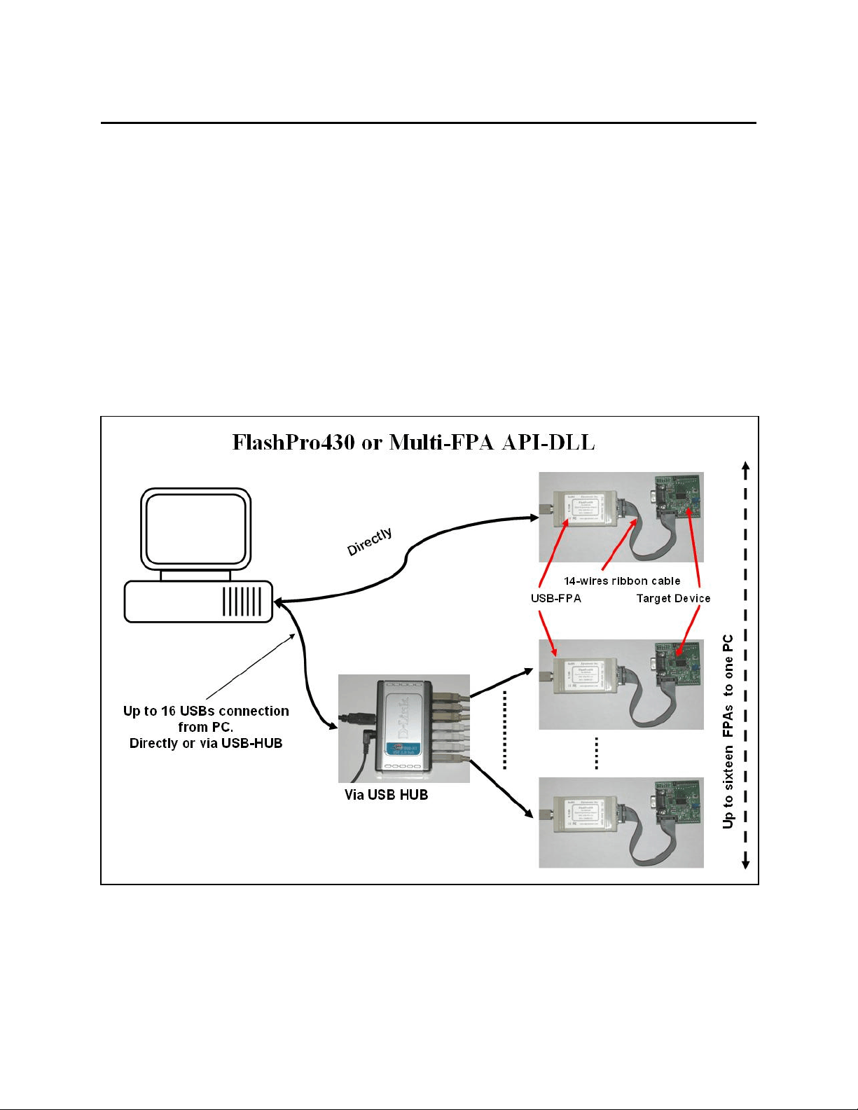
Figure 1.1 shows the connections between PC and up to sixteen programming adapters. The
FPAs can be connected to PC USB ports directly or via USB-HUB. Direct connection to the PC is
faster but if the PC does not have required number of USB ports, then USB-HUB can be used. The
USB-HUB should be fast, otherwise speed degradation can be noticed. When the USB hub is used,
then the D-Link’s Model No: DUB-H7, P/N BDUBH7..A2 USB 2.0 HUB is recommended.
Figure 1.1
9
Page 10
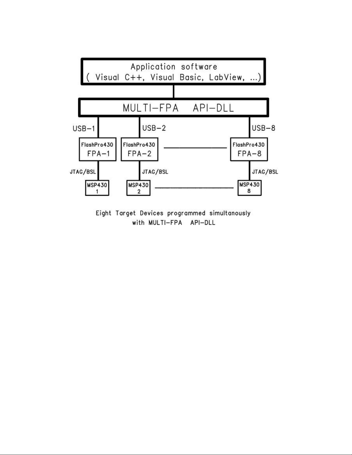
Block diagram of the Multi-FPA application DLL is presented on the Figure 1.2.
Figure 1.2
To support this new Multi-FPA API-DLL feature, the software package contains seventeen dll files
- the Multi-FPA API-DLL selector
- sixteen standard single FPAs API-DLLs (or one UIF API-DLL)
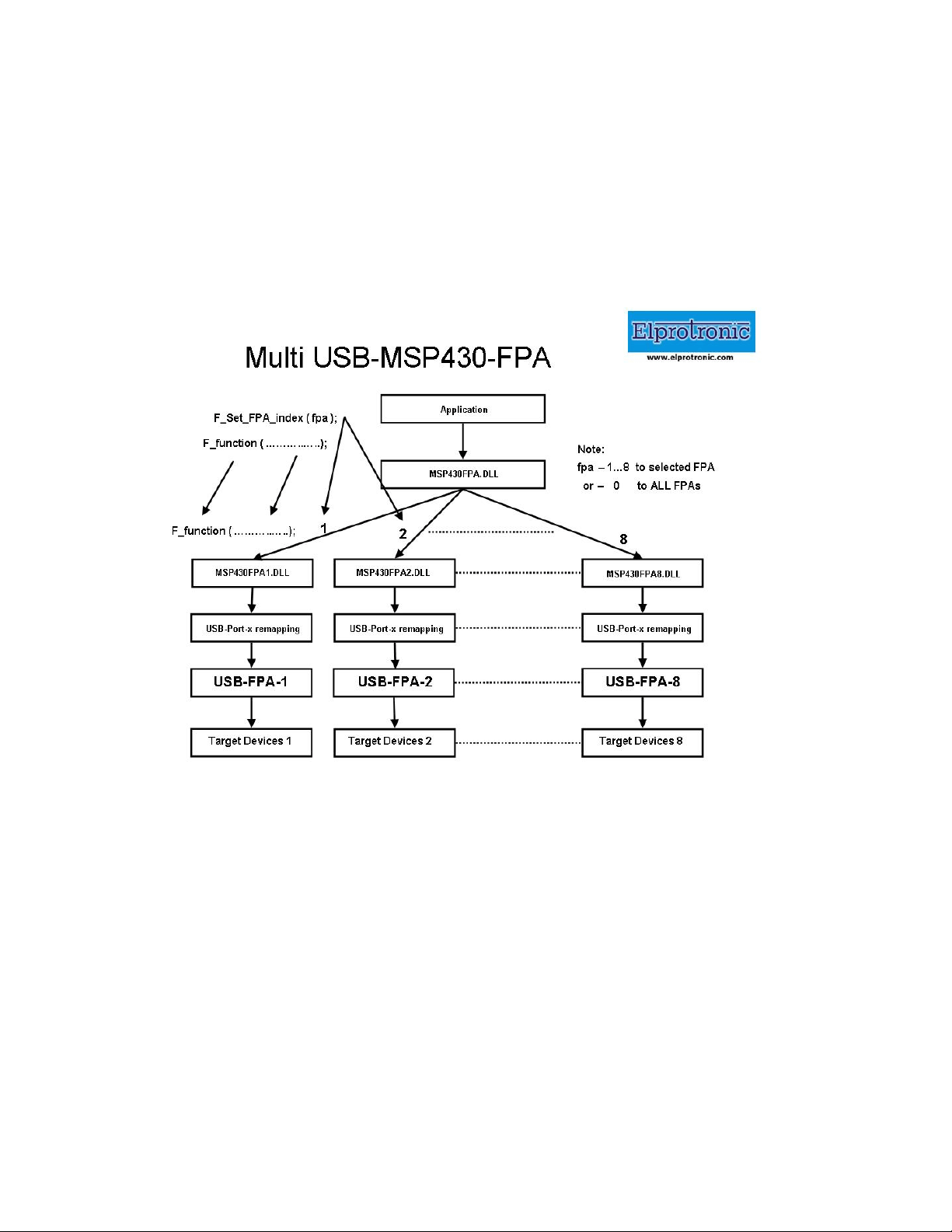
Figure 1.3 shows the logical connections between these dll files.
The main Multi-FPA file (FPA-selector - MSP430FPA.DLL) allows to transfer API-DLL functions
coming from application software to desired single application dll (MSP430FPA1.DLL to
MSP430FPA64.DLL or MSPFET430UIF1.DLL).
The MSP430FPA.DLL file is transparent for all API-DLL functions implemented in the single FPA
API-DLLs functions. Desired destination FPA can be selected using the function
F_Set_FPA_index( fpa );
where the
fpa = 1 to 64 when only one desired FPA required to be selected
or fpa = 0 when ALL active FPAs should be selected.
10
Page 11
The selected FPA index modified by the F_Set_FPA_index( fpa ) instruction can be modified at any
time. By default, the FPA index is 1 and if only one FPA is used then fpa index does not need to be
initialized or modified. When the fpa index 1 to 64 is used, then the result is coming back to
application software from the single API-DLL via transparent Multi-FPA dll. When fpa index is 0
(ALL-FPAs) and results are the same from all FPAs, then the same result is passing back to
application software. If results are not the same, then the Multi-FPA dll is returning back value -1
Figure 1.3
(minus 1) and all recently received results can be read individually using function
F_LastStatus( fpa )
Most of the implemented functions allows to use the determined fpa index 1 to 64 or 0 (ALL-FPAs).
When functions return specific value back, like read data etc, then only determined FPA index can
be used ( fpa index from 1 to 64). When the fpa index is 0 (ALL-FPAs) then almost all functions are
executed simultaneously. Less critical functions are executed sequentially from FPA-1 up to FPA-64
but that process can not be seen from the application software.
11
Page 12

When the inactive fpa index is selected, then return value from selected function is -2 (minus 2).
When all fpa has been selected (fpa index = 0) then only active FPAs will be serviced. For example
if only one FPA is active and fpa index=0, then only one FPA will be used. It is save to prepare the
universal application software that allows to remote control up to sixteen FPAs and on the startup
activate only desired number of FPAs.
It should be noticed, that all single API-DLLs used with the Multi-FPA DLL are fully independent
to each other. From that point of view it is not required that transferred data to one FPA should be
the same as the transferred data to the others FPAs. For example code data downloaded to FPA-1
can be different that the code data downloaded to the FPA-2, FPA-3 etc. But even in this case the
programming process can be done simultaneously. In this case the desired code should be read from
the code file and saved in the API-DLL-1, next code file data should be saved in the API-DLL-2 etc.
When it is done, then the F_AutoProgram can be executed simultaneously with selected all active
FPAs. All FPAs will be serviced by his own API-DLL and data packages saved in these dlls.
The following commands are supported in the DLL library:
Initialization and termination communication with the programming adapter,
Programmer configuration setup,
Programming report message,
Code data and password data read from the file,
DC power target from the programming adapter,
Reset target device,
Auto program target device ( erase, blank check, program and verify),
Password or fuse verification,
All or selected part of memory erase,
All or selected part of memory blank check,
All or selected part of memory write,
All or selected part of memory verify,
All or selected part of memory read,
Open or close communication with the target device,
Selected memory segment erase,
Selected part of memory blank check,
Selected part of memory segment write,
Selected part of memory segment read,
Security fuse blow.
12
Page 13

The MSP430 Flash Programmer software package contains all required files to remotely control
programmer from a software application. When software package is installed then by default the
DLL file, library file and header file are located in:
C:\Program Files\Elprotronic\MSP430\USB FlashPro430\API-DLL
MSP430FPA.dll - Multi-FPA selection/distribution DLL
MSP430FPA1.dll - DLL for Elprotronic’s USB-MSP430-FPA
MSPFET430UIF1.dll - DLL fro TI’s MSP-FET430UIF
MSPPrg-Dll.h - header file for MS VC++
MSPPrg-Dos-Dll.h - header file for Borland, DOS etc.
MSP430FPA-BC.lib - lib file for Borland VC++
MSP430FPA.lib - lib file for MS VC++
config.ini - default configuration file for the FPAs
FPAs-setup.ini - FPAs- vs USB / UIF ports configuration file
or
C:\Program Files\Elprotronic\MSP430\FET-Pro430\API-DLL
MSP430FPA.dll - Multi-FPA selection/distribution DLL
MSPFET430UIF1.dll - DLL fro TI’s MSP-FET430UIF
MSPPrg-Dll.h - header file for C++
MSPPrg-Dos-Dll.h - header file for Borland, DOS etc.
MSP430FPA.lib - lib file for MS VC++
MSP430FPA-BC.lib - lib file for Borland VC++
config.ini - default configuration file for the FPAs
FPAs-setup.ini - FPAs- vs UIF ports configuration file
The API-DLL package in the USB FlashPro430 and in the FET-Pro430 subdirectories are exactly
the same. However for the simplicity the dll file for the USB-MSP430-FPA adapter is not included
in the FET-Pro430 package, since the only MSP-FET430UIF adapter will be used. Make sure that
your application software will not call the USB-MSP430-FPA adapter if the dll for this adapter is
not present. When the USB-MSP430-FPA adapter is used, then the package from the first
subdirectory that contains the MSP430FPA1.dll for the USB-MSP430-FPA adapter should be used.
In this package the MSPFET430UIF1.dll for the MSP-FET430UIF adapter is also included and
allows to use the USB-MSP430-FPA adapter (or adapters) only, the MSP-FET430UIF adapter or
both type of adapters at the same time. The entry dll (MSP430FPA.dll - dll selector) is selecting the
desired dll vs used adapter.
The entry dll (MSP430FPA.dll) contains two groups of the same functions used in C++
application and Visual Basic applications All procedure names used in the Visual Basic are starting
13
Page 14

from VB_xxxx, (and have the _stdcall calling declaration) when procedure names used in the C++
are starting from F_xxxx (and have the _Cdecl calling declaration).
Reminding files listed above are required in run time - to initialize the flash programming
adapter. The config.ini is optional, if not present then default configuration is created.
When the MS VC++ application is created, then following files should be copied to the source
application directory:
MSPPrg-Dll.h - header file for C++
MSP430FPA.lib - lib file for C++
and to the release/debug application directory
MSP430FPA.dll - Multi-FPA selection/distribution DLL
MSP430FPA1.dll - DLL for Elprotronic’s USB-MSP430-FPA
MSPFET430UIF1.dll - DLL fro TI’s MSP-FET430UIF
config.ini - default configuration file for the FPAs
FPAs-setup.ini - (optiona) FPAs- vs USB ports configuration file
Executable application software package in C++ the requires following files
MSP430FPA.dll - Multi-FPA selection/distribution DLL
MSP430FPA1.dll - DLL for Elprotronic’s USB-MSP430-FPA
MSPFET430UIF1.dll - DLL fro TI’s MSP-FET430UIF
config.ini - default configuration file for the FPAs
FPAs-setup.ini - (optiona) FPAs- vs USB ports configuration file
When application in Visual Basic is created, then following files should be copied to the source or
executable application directory:
MSP430FPA.dll - Multi-FPA selection/distribution DLL
MSP430FPA1.dll - DLL for Elprotronic’s USB-MSP430-FPA
MSPFET430UIF1.dll - DLL fro TI’s MSP-FET430UIF
config.ini
FPAs-setup.ini - FPAs- vs USB ports configuration file
When LabView application is created, then following files taken form the location
C:\Program Files\Elprotronic\MSP430\USB FlashPro430\LabView
should be copied to the source or executable application directory:
FlashPro430-Labview.dll - LabView library
MSP430FPA.dll - Multi-FPA selection/distribution DLL
MSP430FPA1.dll - DLL for Elprotronic’s USB-MSP430-FPA
MSPFET430UIF1.dll - DLL fro TI’s MSP-FET430UIF
14
Page 15

config.ini
FPAs-setup.ini - FPAs- vs USB ports configuration file
All these files ‘as is’ should be copied to destination location, where application software using DLL
library of the MSP430 Flash programmer is installed. The config.ini file has default setup
information. The config.ini file can be modified and taken directly form the MSP430 Flash
Programmer application software. To create required config.ini file the standard MSP430 Flash
programmer software should be open and required setup (memory option, JTAG/SBW/BSL interface
select etc) should be created. When this is done, programming software should be closed and the
config.ini file with the latest saved configuration copied to destination location. Note, that the
configuration setup can be modified using DLL library function.
Software package has a demo software written under Visual C++.net , Visual Basic.net and
LabVIEW - version 7.1. All files and source code are located in:
C:\Program Files\Elprotronic\MSP430\USB FlashPro430\API-DLL-Demo\Cpp
C:\Program Files\Elprotronic\MSP430\USB FlashPro430\API-DLL-Demo\VBnet
C:\Program Files\Elprotronic\MSP430\USB FlashPro430\API-DLL-Demo\VB6
C:\Program Files\Elprotronic\MSP430\USB FlashPro430\LabView
1.1 Using TI’s MSP-FET430UIF adapter
The Multi-FPA API-DLL version 4.0 and higher allows to control the TI’s MSP-FET430UIF
or EZ430 stick adapter with the same list of instructions as are used for the MSP-MSP430-FPA
adapters. The API-DLL is prepared mostly for the flash programming only and from that reason an
available list of instructions in the MSP-FET430UIF used for debugging are not used in the API-
DLL. The care should be taken, that some of the features available in the USB-MSP430-FPA
adapters are not supported in the MSP-FET430UIF adapters and vice-verse. The MSP-FET430UIF
does not support the BSL communication interface and also does not allow to calibrate the DCO
frequency. These option should be disabled in software (see software configuration) if the MSP-
FET430UIF adapter is used.
The API-DLL structure and list of instructions for the MSP-FET430UIF allows to use current
application software used for the USB-MSP430-FPA adapters without modification. Only the latest
DLLs should replace the old dlls. Also the MSPFET430UIF1.dll file should be plased with the other
dlls if the MSP-FET430UIF is used. When the USB-MSP430-FPA adapter is not used, then the
MSP430FPA1.dll can be removed. Make sure that the main dll - MSP430FPA.dll is always
installed. The MSPFET430UIF1.dll file is protected and can work without access key only first 30
15
Page 16
days after first activation. After this time the access key is required. If the TI’s MSP-FET430UIF
adapter is not used, then the MSPFET430UIF.dll file can be removed to avoid the pop-up messages
with information regarding access key installation, or in the start-up definition the option - ANY
adapter should not be used. Use the FPAs serial number or FPA definition to avoid activation the
API-DLL servicing the TI’s MSP-FET430UIF adapter, or vice-verse - when the MSP-FET430UIF
adapter is used only, then do not use ANY adapter definition. Use the UIF definition instead ANY
adapter (‘*’).
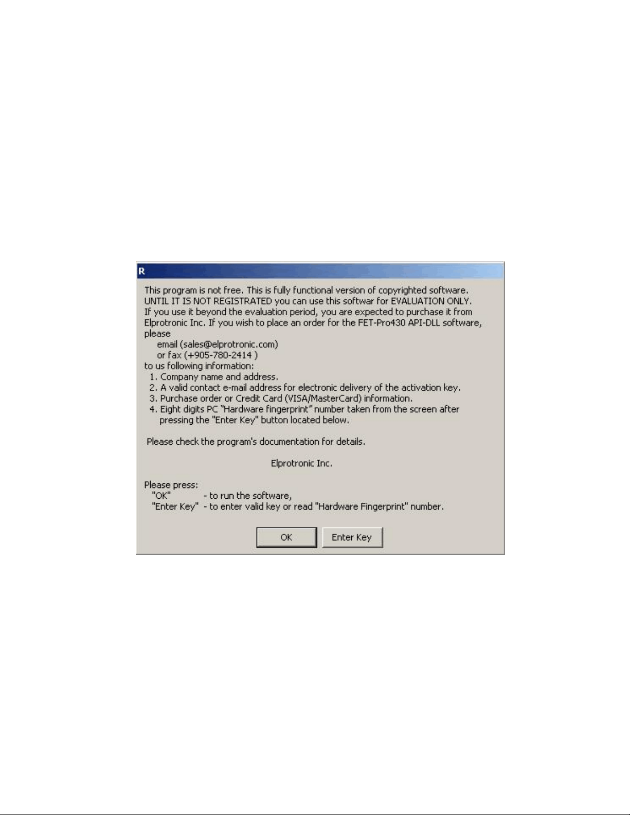
When the access key for the MSPFET430UIF.dll file is not installed, then the following pop-
up message will be displayed every time when the dll is activated.
Figure 1.4
Since the application software can install and close the dll a few times on the startup then the pop-up
messages can be reentered even - 2-4 times on the startup. Press OK button and go head. After expire
time the dll without valid access key will reject the communication with application software. When
the access key is installed, then the pop-up messages are not displayed any more.
16
Page 17

2. Getting Started
2.1 Self Test Program
The software package contains the FlashPro430 Self Test program, that allows to test functionality
of the ONE flash programming adapter, users target device and connections between these units.
Software package use the Multi-FPA API-DLLs. In the test results printout are listed the DLL
functions with syntax, that has been used. This printout is useful to find-out source of the problems,
as well as can be used at the startup when your application software uses one programming adapter
only. Software can be activated from the Start menu
Start -> Programs -> Elprotronic-Flash Programmers -> (MSP430) FlashPro430 -> FlashPro430 Self Test
or by running the program FlashPro430SelfTest.exe from the location
C:\Program Files\Elprotronic\MSP430\USB FlashPro430\SelfTest
The same software package can be found in the FET-Pro430 subdirectory, if the FET-Pro430
software is installed.
The Figure 2.1 presents the GUI of the FlashPro430 / FET-Pro430 Self Test.
Connect the Flash Programming Adapter (USB-MSP430-FPA or MSP-FET430UIF) to PC (USB
port), connect your target device to adapter, select desired options in following selectors (see Figure
2.1) - “Target Device”, “Target’s Vcc” “Interface” and “Reset Pulse width”. When it is done
then press the button “TEST”. When test is finished, then check if there is no any errors. Detailed
test report is displayed. The test report can be paste to Notepad and saved if required.
Note: When the MSP-FET430UIF adapter is used then only two interface can be selected
- JTAG or Spy-Bi-Wire with fixed communication speed. The BSL interface is not
supported in this adapter.
Following conditions are used during the test:
1. JTAG and Spy-Bi-Wire interface is used:
* Erased and programmed MAIN memory only. The info memory (0x1000 to 0x10FF)
is not erased and not modified. The DCO calibration data in the F2xx are not
modified. During the test it can be displayed warning that All memory blank check
failed, that of course is normal. But selected memory blank check must be OK (the
full MAIN memory in this case).
17
Page 18
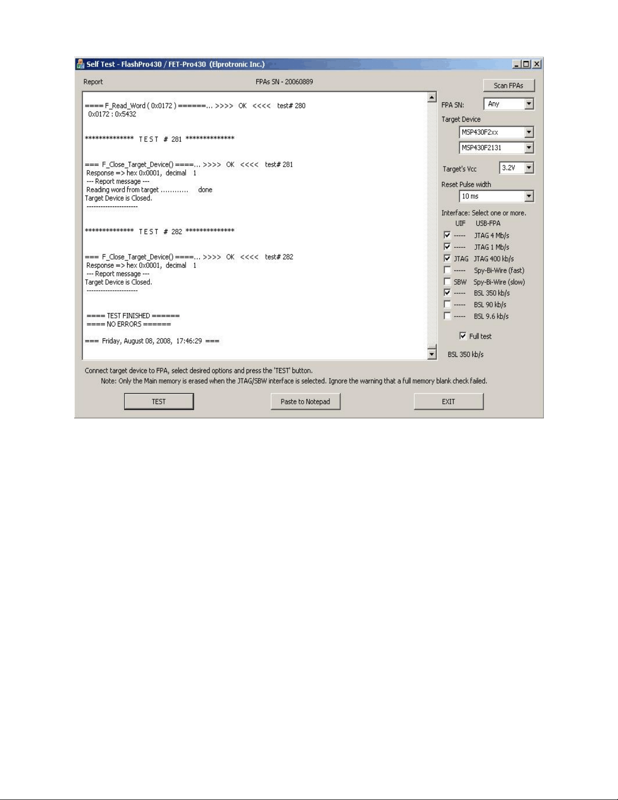
Figure 2.1
* All bytes of the main memory are erased, blank checked and programmed with the
randomly generated data used as a code data. Whole MAIN memory content is
verified (check sum) and also read whole data and verified byte by byte.
* One sector (location 0xFC00 to 0xFDFF) is erased and blank checked. Also contents
of the two closer sectors are verified if there are not erased. Small block of data are
saved and verified in the mentioned sector.
* Word write/read to TACCR0 (0x172) register.
* Byte/Word manipulation are used in the part of the RAM.
2. BSL interface is used (not supported in the MSP-FET430UIF):
* Due to unknown access password, the whole Flash memory - MAIN and INFO are
erased. In the F2xx microcontrollers the DCO calibration data will be erased. There
is no way to save the DCO data if the BSL password is unknown. The DCO data can
18
Page 19

be calibrated using the FlashPro430 GUI package software when the JTAG or Spy-
Bi-Wire access is available (when the JTAG fuse is not blown). See the FlashPro430
manual for details.
* All MAIN memory is tested in the same way as it is used with the JTAG/Spy-Bi-
Wire interface
* Word write/read to TACCR0 (0x172) register.
* Access to RAM if size of the RAM if higher then 256 bytes. Access to RAM space
0x200 to 0x2FF is blocked due to stack and firmware located in this RAM location.
Note: The first test (Vcc value when the power is OFF) can be failed, if the external power is
connected or if the blocking capacitor on your target device connected to the Vcc line if high.
The Vcc should be below 0.4V when the power is OFF, tested 2 seconds after switching-off
the power from FPA, otherwise test failed.
The Self Test programming software package is located in directory
C:\Program Files\Elprotronic\MSP430\USB FlashPro430\SelfTest
or
C:\Program Files\Elprotronic\MSP430\FET-Pro430\SelfTest
and contains following files
MSP430FPA.dll - Multi-FPA selection/distribution DLL
MSP430FPA1.dll - USB-FPA DLL
MSPFET430UIF1.dll - DLL fro TI’s MSP-FET430UIF
config.ini - default configuration file for the FPAs
FlashPro430SelfTest.exe - executable file
To run the executable file FlashPro430SelfTest.exe it in the other location the files listed above
should be copied “as is” to destination directory.
2.2 MyMSP430Prg Projects
The MyMSP430Prg projects are examples of using the Multi-FPA API-DLL with Microsoft Visual
Studio 7.0 (2002) and for Microsoft Visual Basic 6.0. They are intended to help users create their
own application that uses the API-DLL by providing a simple starting point. When using Visual
Studio C++ include the following files should be included to your program:
MSP430FPA.lib
MSPPrg-Dll.h
MspFPA-Lib.h
19
Page 20

MspFPA-Lib.cpp
MSP430SamplePrg.h
MSP430SamplePrg.cpp
The above files are located in the following directory:
...\Elprotronic\MSP430\USB FlashPro430\API-DLL-MyPrg\Cpp\scr
or
...\Elprotronic\MSP430\FET-Pro430\API-DLL-MyPrg\Cpp\scr
Files MSP430SamplePrg.cpp and MSP430SamplePrg.h can be modified in a way that suits your
application. However, the remaining files should not be modified.
To run your application you will need to allow your application access to the Multi-FPA dynamically
linked library. A simple way to do this is to copy the following files into your directory where
executable file is located:
MSP430FPA.dll
MSP430FPA1.dll - required if the USB-MSP430-FPA adapter is used
MSPFET430UIF1.dll - required if the TI’s MSP-FET430UIF is used
Config.ini (optional)
The easy demo project MyMSP430Prg uses API-DLLs and files listed above is located in directory
...\Elprotronic\MSP430\USB FlashPro430\API-DLL-MyPrg\Cpp\MyMSP430Prg
or
...\Elprotronic\MSP430\FET-Pro430\API-DLL-MyPrg\Cpp\MyMSP430Prg
and are included for demonstration purposes only. The sample project can be opened by selecting
the project file MyMSP430Prg.vcproj located in directory
...\Elprotronic\MSP430\USB FlashPro430\API-DLL-MyPrg\Cpp\MyMSP430Prg
or
...\Elprotronic\MSP430\FET-Pro430\API-DLL-MyPrg\Cpp\MyMSP430Prg
The following dialogue box will be displayed when project executed (see figure 2.2).
Dialogue box contains few buttons, that call procedures listed in the mentioned above files. See
contents in the MyMSP430Prg.cpp file located in the project directory, how these procedures are
called from application software. There are several useful procedures located in the MspFPA-
20
Page 21
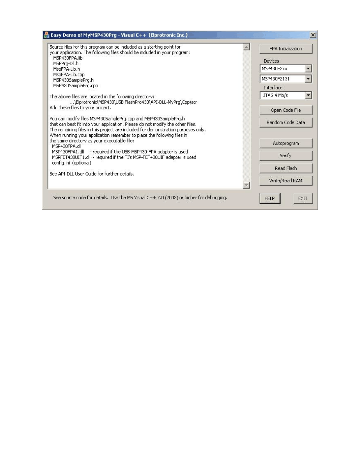
Figure 2.2
Lib.cpp file that significantly simplify the FPA initialization process. See comments for each
procedures located in this file.
The first procedure named
get_FPA_and_MSP_list(..........)
searches all FPAs connected to your PC via USB ports. As the results, adapter serial numbers of the
detected FPAs are located in the FPA_SN_list[k] where k = 0 up to 15. Up to sixteen FPA SN can
be located in this data block. SN list are located starting from FPA_SN_list[0]. The same procedure
also takes a list of supported MSP microcontrollers containing MCU name, flash start and end
addresses etc. from API-DLL .The MCU list is saved in the following structure
typedef struct
{
char name[DEVICE_NAME_SIZE];
int index;
long flash_start_addr;
long flash_end_addr;
long info_flash_start_addr;
21
Page 22

long info_segm_size;
long no_of_info_segm;
long RAM_size;
int group;
int double_ID;
} DEVICELIST;
DEVICELIST DeviceList[300];
Up to 300 MCUs can be saved in DeviceList. When required, the size of this data block can be
increased in the future. Currently, device list contains about 130 MCUs. The MCU names in the
DeviceList are sorted in alphabetic order. Alphabetical order is convenient for users, however the
API-DLL requires fixed MCU index when selecting the particular MCU. In the structure above the
MCU index required by API-DLL is located in
DeviceList[k].index
and procedure setting the required MCU becomes as follows
F_SetConfig( CFG_MICROCONTROLLER, DeviceList[k].index );
The second procedure that can be called after the get_FPA_and_MSP_list(..........) procedure has
finished successfully, is the AssignFPAs( ......... ) procedure that activates the DLLs and assign
desired FPAs. When these two procedures are finished successfully, the programmer is ready to
work. See procedure
FP430_FPA_initialization()
located in MyMSP430SamplePrg.cpp file how to call procedures above and what the next step
should be.
The same procedures as described above have been implemented in the software package using
Visual Basic 6.0. When the Visual Basic 6.0 is used, then the following files should be included to
your program
FlashPro430Def.bas
MspFPA-Lib.bas
MSP430SamplePrg.bas
The above files are located in the following directory
22
Page 23

...\Elprotronic\MSP430\USB FlashPro430\API-DLL-MyPrg\VB6
When running your application, remember tp place the following files in the same directory as your
executable file:
MSP430FPA.dll
MSP430FPA1.dll - required if the USB-MSP430-FPA adapter is used
MSPFET430UIF1.dll - required if the TI’s MSP-FET430UIF is used
Config.ini (optional)
You can modify file MSP430SamplePrg.bas to best fit into your application needs. Other files should
not be modified. The remaining files in this project are located in directory
...\Elprotronic\MSP430\USB FlashPro430\API-DLL-MyPrg\VB6
and are included for demonstration purposes only. Project can be activated by selecting the project
file MyMSP430Prg.vbp located in directory
...\Elprotronic\MSP430\USB FlashPro430\API-DLL-MyPrg\VB6
All procedures implemented in Visual Basic 6.0 are the same as those implemented in Visual C++.
See description above. Procedures written in VB6 are located in the MspFPA-Lib.bas file. Example
how to use these procedures are located in the MSP430SamplePrg.bas file. API-DLL function
declaration and constant definition are located in the FlashPro430Def.bas file.
2.3 API DLL Demo Program
Application DLLs files are the same for the application software written under Visual C++, Visual
Basic, LabView etc. First should be created destination directory, where the executable files and
DLLs will be located. Make a copy off all required files from the Elprotronic’s directory to your
destination directory. The files described in the chapter 1 should be copied to the executable
destination directory. It is recommended to use the demo program to verify if the setup in your PC
and destination directory is done correctly.
The Demo program is small GUI program with a lot of buttons allowing to separately call
functions using DLL library package software. Source code and all related project files are located
in the following directory:
C:\Program Files\Elprotronic\MSP430\USB FlashPro430\API-DLL-Demo\Cpp\Exe
VBnet version
23
Page 24

C:\Program Files\Elprotronic\MSP430\USB FlashPro430\API-DLL-Demo\VBnet
VB6 version
C:\Program Files\Elprotronic\MSP430\USB FlashPro430\API-DLL-Demo\VB6
Labview (ver 7.1)
C:\Program Files\Elprotronic\MSP430\USB FlashPro430\LabView
when the FlashPro430 package is used, or in directory
C:\Program Files\Elprotronic\MSP430\FET-Pro430\API-DLL-Demo\Cpp\Exe
VBnet version
C:\Program Files\Elprotronic\MSP430\FET-FlashPro430\API-DLL-Demo\VBnet
VB6 version
C:\Program Files\Elprotronic\MSP430\FET-FlashPro430\API-DLL-Demo\VB6
Labview (ver 7.1)
C:\Program Files\Elprotronic\MSP430\FET-FlashPro430\LabView
when the FET-Pro430 package is used.
It is recommended to also copy the demo software
FlashPro-Multi-FPA-Demo.exe
taken from the Elprotronic’s directory (default location)
C:\Program Files\Elprotronic\MSP430\USB FlashPro430\API-DLL-Demo\Cpp\Exe
To make a run the demo program, then the following files should be located in the same directory
where the executable program in located. Assume that the demo program
FlashPro-Multi-FPA-Demo.exe
is used, then also the following files should be located in the same directory
MSP430FPA.dll - Multi-FPA selection/distribution DLL
MSP430FPA1.dll - required if the USB-MSP430-FPA adapter is used
MSPFET430UIF1.dll - required if the TI’s MSP-FET430UIF is used
config.ini - (optional) default configuration file for the FPAs
The FlashPro-Multi-FPA-Demo.exe program contains GUI (Figure 2.3) that allows to activate
one or more Flash Programming Adapters (FPA), TI’s MSP-FET430UIF adapter or mixed like in
an example below - USB-MSP430-FPA and MSP-FET430UIF adapters . When one adapter is used
then the button Open Instances And FPA (“*# *”) should be pressed. The first detected FPA
24
Page 25
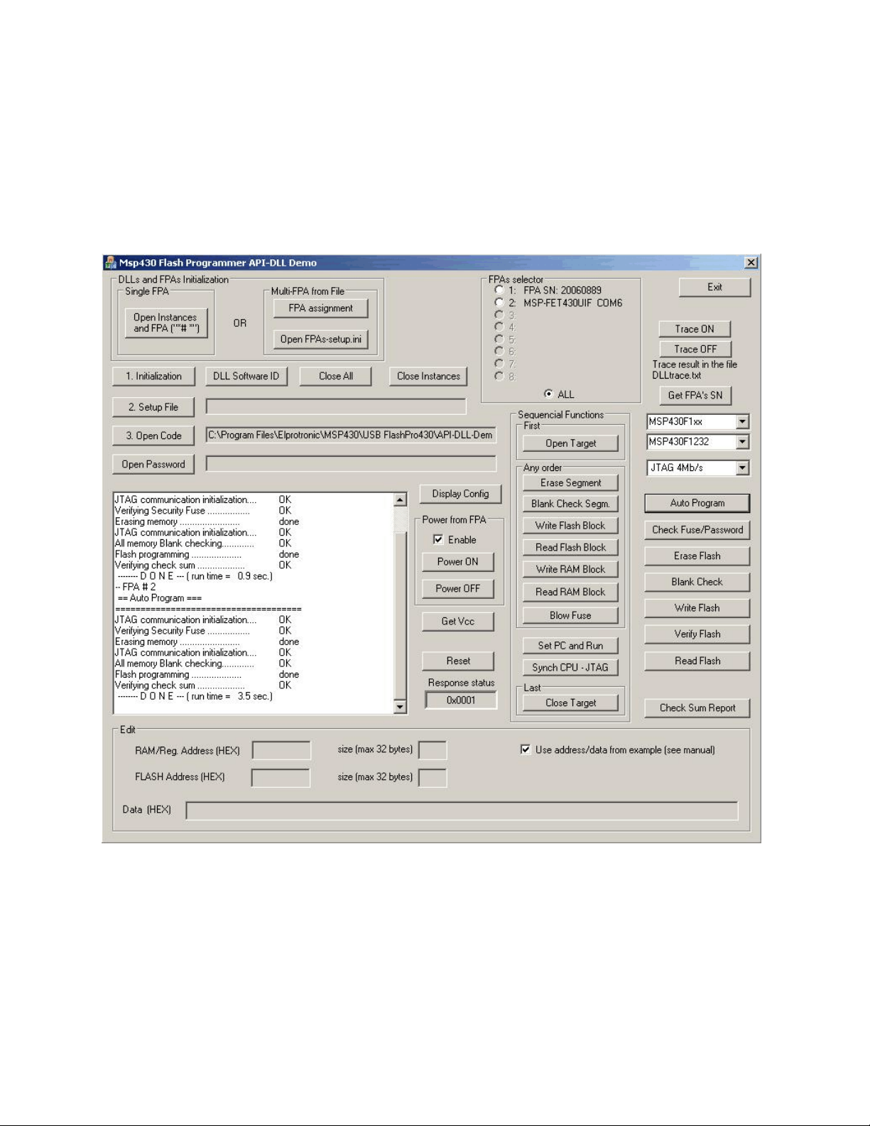
adapter connected to USB port(s) will be activated. If the USB-MSP430-FPA adapter is not present,
then software is searching for the MSP-FET430UIF adapter. If more then one adapter are connected,
then only fisrt will be used, all others adapters will be ignored. When the adapter is accepted by
software, then the 1. Initialization button must be pressed. When the 1. Initialization button is
pressed then communication with the programming adapter is initialized. Now the desired
configuration setup should be downloaded to DLLs and programming adapters (using button ‘2.
Setup File’ ), code file with data to be downloaded to target devices (using button ‘3. Open Code’)
Figure 2.4 Demo program dialogue screen using DLLs.
and password file, if required (using button ‘Open Password’ ). Setup file can be created using
standard FlashPro430 programming software. Setup file used in the FlashPro430 has the same
format as the configuration file used in the application DLL.
25
Page 26

All other buttons used in the demo program are calling one API-DLL function per one button.
For example button ‘Autoprogram’ is calling
F_Autoprogram(1);
function, button ‘Open Target’ is calling
F_OpenTarget();
function etc. Using any button pressing sequence it is possible to test how the application dll is
responding for these combinations. Some of the buttons assigning extra data to be able to simulate
some write/erase procedures as follows.
* button ‘Erase segment’ allows to erase segment located on address 0x1000 to 0x107F.
* button ‘Blank Check Segm.’ allows to check the segment defined in the ‘Erase segment’
button.
* button ‘Write Flash Block’ allows to write block data
0x01, 0x02, 0x03, 0x04, 0x05, 0x06, 0x07, 0x08
to flash location starting from 0x1020.
* button ‘Read Flash Block’ allows to read data from flash addresses 0x1000 to 0x103F.
When the check mark named ‘Use address/data from example (see manual) ’ in the ‘Edit’ frame
is unmarked, then edit fields becomes active and addresses to the function described above can
customized and defined in the ‘RAM Address (HEX)’ or ‘Flash Address (HEX)’. Content of data
can be specified in the ‘Data (HEX)’ field. All data should be separated by white character (space).
Maximum size data should be specified in the ‘size (max 32 bytes)’ fields (RAM or Flash).
When any button related to encapsulated functions is used ( ‘Autoprogram’, ‘Erase Flash’, ‘Blank
Check’, ‘Write Flash’, ‘Verify Flash’ ) then data taken from the code file is used ( press button ‘3.
Open Code’ to take desired code data).
Described demo program allows to understand how to use the dll functions in the application
software.
When more then one adapter is connected to PC, then the Multi-FPA API-DLL feature should be
activated. Currently up to 64 adapters can be controlled from one application software. For simplicity
the presented demo program can control up to eight adapters only. The Multi-FPA API-DLL can
assign specified FPA serial number to desired FPA index or specified COM port or eq. serial number
for the MSP-FET430UIF, where index can be from 1 up to 64 (1 to 8 in presented demo software).
At the startup software is scanning all available FPAs and MSP-FET430UIFs and assigning adapters
according to defined FPA’s serial number list. See the F_OpenInstancesAndFPAs(..) Instruction for
details. Configuration will be always the same regardless used the FPA vs USB port location. All
26
Page 27

adapters not specified in the desired FPA list will be ignored. Make sure that the desired list uses
correct FPAs serial numbers. The FPA serial number is printed in the FPA’s label. When the MSP-
FET430UIF is used then check the assigned port for particular adapter (use FET-Pro430 software
for it) or use the UIF definition to accept any UIF-MSP430UIF adapter. Note, that only one MSP-
FET430UIF can be used, so definition UIF can be used for simplicity.
Assume, that we are using one USB-MSP430-FPA programming adapter and one MSP-FET430UIF
adapter. In the next step, the configuration file should be created, that contains list off all FPA’s used
in the application. Using the Notepad editor open the default FPA’s configuration file ‘FPAs-
setup.ini’ taken from your destination location (copied before from Elprotronic’s directory) and write
the serial numbers or IDs of used adapters. Take a serial numbers from the FPAs labels and write
it on the desired FPAs locations FPA-1 up to FPA-8. For two adapters as above the configuration
file can use an IDs - FPA and UIF only as follows:
;===================================================================
; USB-MSP430-FPA configuration setup *
; Elprotronic Inc. *
;------------------------------------------------------------------; up to eight FPA can be specified and connected via USB to PC *
; syntax: *
; FPA-x Serial Number *
; where FPA-x can be FPA-1, FPA-2, FPA-3 .... up to FPA-8 *
; Serial number - get serial number ir ID from the desires *
; adapter's label *
; Minimum one FPA's must be specified *
; FPA-x order - any *
; *
; e.g (without semicolon - comment) *
; Available options for Elprotronic's FPA's: *
; ANY adapter FPA or UIF - * *
; or ANY FPA adapter - FPA *
; or FPA with serial number only eg. - 20080123 *
; *
; Available options for TI's MSP-FET430UIF *
; ANY adapter FPA or UIF - * *
; or ANY UIF adapter - UIF *
; or UIF used COM x port - COM4 *
; or UIF used HID x port - HID3 *
; *
;FPA-1 20050116 *
;FPA-3 20050199 *
;FPA-5 20050198 *
;===================================================================
FPA-1 FPA
FPA-2 UIF
27
Page 28

Note, that only lines without comments (without semicolon on the front ) are used by software. All
lines with comment are ignored. The FPA’s serial numbers and FPA’s indexes can be listed in any
order and with gap like FPA-1, FPA-5 etc. without FPA-2, 3 etc. Minimum one valid FPA with
correct ID or SN must be specified. Up to sixteen adapters can be declared. When the FPA’s
configuration file is created then file should be saved using name starting from FPA and with
extention ini e.g FPAs-setup.ini.
Connect all required adapters to USB connectors and run the FlashPro-Multi-FPA-Demo.exe demo
software. First the DLL instances should be opened and all connected FPA’s should be assigned to
desired FPA’s indexes. When the button ‘FPA assigment’ is pressed, then the DLL function named
F_OpenInstancesAndFPAs( FileName );
is called. This function is taking list of defined FPA’s numbers or IDs from the FPAs configuration
file and assigning all adapters to desired FPA indexes (1 to64). Number of instances to be opened
is calculated automatically, one per available and valid adapter. On described example with two
asdapters in the ‘FPAs selector’ will display two valid adapters with list of used FPAs’ serial
numbers or COM port for the MSP-FET430UIF. All, others FPA-x fields will be disabled. In this
example only two DLL instances becomes opened. Valid FPA indexes becomes 1,2 and ALL.
When the dll instances becomes opened and FPA adapter assigned to desired FPA’s indexes, then
the initialization procedure F_Initialization() must be called. It is recommended to initialize all
opened instances by calling function
F_Set_FPA_index(ALL_ACTIVE_FPA);
when more then one FPA adapter is used, or
F_Set_FPA_index(1);
when one FPA (assigned to index 1 by default) is used
prior to initialization function
F_Initialization();
On the demo program initialization procedure all these procedures are called when the button ‘1.
Initialization’ is pressed. Now adapters are ready to take other commands. In the demo above the
‘Autoprogram’ button has been used to download code simultaneously to two target devices
MSP430F1232 via two types of programming adapters - USB-MSP430-FPA and TI’s MSP-
FET430UIF. See programming report in the Report window - under FPA-#1 report taken from first
adapter, and under FPA #2 - report taken from the second adapter. In reality always the same type
adapters will be used, but this example showing flexibility of the API-DLL, that allows to swap
adapters and use application software with different adapters without modifying an application
software.
28
Page 29

3. Example with API DLL
3.1 Example with single FPA
The code example described below uses one programming adapter. The Multi-FPA API-DLL
selector should be select for FPA-1 only. The fpa_index should be set to 1 or should be unmodified.
The default value of the fpa_index when one adapter is detected only is 1.
Initialization opening procedure for the USB-FPA can be as follows:
response = F_OpenInstancesAndFPAs( “*# *” );
// DLL and FPA (one only) initialization
if( response == 0 )
{
//The FPA has not been found. Exit from the program.
}
F_Set_FPA_index( 1 ); // select FPA 1 for
F_Initialization( ); // init FPA
Below is an example of the simplified (without error handling procedures) application
program written in C++ that allows to initialize one FPA, and run an autoprogram with the same
features like an autoprogram in the standard FlashPro430 (GUI) software.
1. Download data to target device
F_OpenInstancesAndFPAs( “*# *” ); // DLL and FPA (one only) initialization
if( response == 0 )
{
//The FPA has not been found. Exit from the program.
}
F_Set_FPA_index( 1 ); // select FPA 1 only
F_Initialization( ); // init FPA
//– functions above initialized at the startup only --- F_ReadConfigFile( filename ); // read configuration data and save
// to API-DLLs
F_ReadCodeFile( format, filename ); // read code data and save to DLL
do
{
status = F_AutoProgram( 1 ); //start autoprogram
if ( status != TRUE )
{
..............................
}
else
29
Page 30

{
................................................
}
} while(1); //make an infinite loop until last target device programmed
.................................................................
//– functions below called at the end of session
F_CloseInstances();
Note: The F_OpenInstancesAndFPAs(..) and F_Initialization() functions should be called once
and the startup and the F_CloseInstances() function should be called as the last one after all
functions are finished in similar way like the FlashPro430 GUI software is opening once
and closed at the end when job is finished. The startup initialization take few seconds (when
the F_OpenInstancesAndFPAs(..) and F_Initialization() are executed) until dll
installation is established and desired firmware downloaded to FPA adapter(s). Application
software should call the initialization procedures at the startup only, and close access to API-
DLL at the end, when all tests of a lot of units are finished. Closing instances and opening
it again is a waist a time.
3.2 Example with Multi-FPA API DLL
The code example described below uses Multi-FPA API-DLL. The multi-FPA API-DLL is a shell
that allows to transfer incoming instructions from application software to desired FPA’s. All
instructions related to single FPA are detailed described in the chapters 4.2, 4.3, 4.4 and 4.4.
Instructions specific to Multi-FPA features described in the chapter 4.1.
Application DLL should be initialized first, before other DLLs instruction can be used.
response = F_OpenInstancesAndFPAs( FPAs-setup.ini );
// DLL and FPA initialization
if( response == 0 )
{
//The FPA has not been found. Exit from the program.
}
F_Set_FPA_index( ALL_ACTIVE_FPA ); // select all FPA’s
F_Initialization( ); // init all FPA’s
In example above number of the opened USB-FPAs are specified in the ‘FPAs-setup.ini’
Below is an example of the simplified (without error handling procedures) application program
written in C++ that allows to initialize all dlls and FPA, and run an autoprogram with the same
features like autoprogram in the standard FlashPro430 application software.
30
Page 31

1. Download data to all target devices (uses USB-FPAs)
response = F_OpenInstancesAndFPAs( FPAs-setup.ini);
// DLL and FPA initialization
if( response == 0 )
{
//The FPA has not been found. Exit from the program.
}
F_Set_FPA_index( ALL_ACTIVE_FPA ); // select all FPA’s
F_Initialization( ); // init all FPA’s
F_ReadConfigFile( filename ); // read configuration data and save
// to all API-DLLs
F_ReadCodeFile( format, filename ); // read code data and save to all
// API-DLLs
do
{
status = F_AutoProgram( 1 );
//start autoprogram-to program all targets simultaneously with
//the same downloaded data to all target devices.
if ( status != TRUE )
{
if ( status == FPA_UNMACHED_RESULTS )
{
for (n=1; n<=MAX_FPA_INDEX; n++ ) status[n] = = F_LastStatus( n);
................................................
}
else
{
................................................
}
}
} while(1); //make an infinite loop until last target device programmed
.................................................................
F_CloseInstances();
Note, that all single API-DLL are independent from each others and it is not required that all data
and configuration should be the same for each API-DLLs (each FPAs, or target devices) . For
example - code data downloaded to the first target device can be the same (but it is not required) as
code data downloaded to second target device etc. In the example below the downloaded code to
target devices are not the same .
2. Download independent data to target devices (uses USB-FPAs)
F_OpenInstancesAndFPAs( FPAs-setup.ini); // DLL and FPA initialization
F_Set_FPA_index( ALL_ACTIVE_FPA ); // select all FPA’s
31
Page 32

F_Initialization( ); // init all FPA’s
.................................................................
F_Set_FPA_index( ALL_ACTIVE_FPA ); // select all FPA’s
F_ReadConfigFile( filename ); // read configuration data and save
// to all API-DLLs
F_Set_FPA_index( 1 ); // select FPA 1
F_ReadCodeFile( format, filename1 ); // read code data and save to
// API-DLL-1
F_Set_FPA_index( 2 ); // select FPA 2
F_ReadCodeFile( format, filename2 ); // read code data and save to
// API-DLL-2
................................................................
F_Set_FPA_index(7 ); // select FPA 7
F_ReadCodeFile( format, filename7 ); // read code data and save to
// API-DLL-7
F_Set_FPA_index( 8 ); // select FPA 8
F_ReadCodeFile( 8, format, filename8 ); // read code data and save to
// API-DLL-8
F_Set_FPA_index( ALL_ACTIVE_FPA ); // select all FPA’s
do
{
status = F_AutoProgram( 1 );
//start autoprogram - to program all targets simultaneously
//with the independent downloaded data to all target devices.
if ( status != TRUE )
{
if ( status == FPA_UNMACHED_RESULTS )
{
for (n=1; n<=MAX_FPA_INDEX; n++ ) status[n] = = F_LastStatus( n);
................................................
}
else
{
................................................
}
}
} while(1); //make an infinite loop until last target device programmed
.................................................................
F_CloseInstances();
See source code in the DEMO program written in Visual C++, Visual Basic or LabView for more
detail.
32
Page 33

4. List of the DLL instructions
Application DLLs files are the same for the application software written under Visual C++,
Visual Basic, LabView etc. From that reason the API-DLL not transfers the pointers from the API-
DLL to application, because Visual Basic (or other software) will not be able to use these functions.
When a lot of data are transferred from API-DLL to application, then these data should be read item
by item.
All DLL instructions are divided to four groups - related to Multi-FPA selector, single FPA
generic, single FPA encapsulated and single FPA sequential instructions. Multi-FPA specific
instructions are related to the Multi-FPA DLL only. Generic instructions are related to initialization
programmer process, while encapsulated and sequential instructions are related to target device’s
function. Encapsulated and sequential instructions can write, read, and erase contents of the target
device’s flash memory.
Multi-FPA specific instructions are related to load and release the single-FPA dlls, selection
of the transparent path and sequential/simultaneous instructions transfer management. All other
instructions are related to single FPAs.
Generic instructions are related to initialization programmer process, configuration setup and
data preparation, Vcc and Reset to the target device. Generic instructions should be called first,
before encapsulated and sequential instruction.
Encapsulated instructions are fully independent executable instructions providing access to
the target device. Encapsulated instructions can be called at any time and in any order. When called
then all initialization communication with the target device is starting first, after that requested
function is executed and at the end communication with the target device is terminated and target
device is released from the programming adapter.
The encapsulated functions should be mainly used for programming target devices. These
functions perform most tasks required during programming in an easy to use format. These functions
use data provided in Code Files, which should be loaded before the encapsulated functions are used.
To augment the functionality of the encapsulated functions, sequential functions can be executed
immediately after to complete the programming process.
33
Page 34

Sequential instructions allow access to the target device in a step-by-step fashion. For
example, a typical sequence of instructions used to read data from the target device would be to open
the target device, then read data and then close the target device. Sequential instruction have access
to the target device only when communication between target device and programming adapter is
initialized. This can be done when Open Target Device instruction is called. When communication
is established, then any number of sequential instruction can be called. When the process is finished,
then at the end Close Target Device instruction should be called. When communication is
terminated, then sequential instructions can not be executed.
Note: Inputs / outputs has been defined as INP_X, and LONG_X. Both of them are defined as 4
bytes long (see MSPPrg-Dll.h header file )
#define INP_X _int32
#define LONG_X _int32
Make sure that an application using the DLL file has the same length of desired data.
Figure 4.1 shows the structure of the Multi-FPA API-DLL. It shows that the Multi-FPA DLL is used
to communicate with the user application as well as the target devices. Each of the target devices is
accessed by a single DLL associated with it. When more then one FPA is needed, up to 64 DLLs can
be created to communicate with up to 64 devices at a time. Each instance of an FPA-DLL contains
its own copy of buffers, as shown in Figure 4.2
Figure 4.1 Multi-FPA API-DLL diagram.
34
Page 35

Figure 4.2 - API-DLL block diagram.
35
Page 36

4.1 Multi-FPA instructions
The Multi-FPA API-DLL instructions are related to Multi-FPA selector only. These
instructions allows to initialize all single applications dlls and select the instruction patch between
application software and desired FPA and sequential/simultaneous instructions transfer management
Up to sixteen independent FPAs can be remotely controlled from the application software. All
instructions from application software can be transferred to one selected FPA or to all FPAs at once.
That feature allows to increase programming speed and also allows to have individual access to any
FPA is required.
F_Trace_ON
F_Trace_ON - This function activate the tracing.
The F_Trace_ON() opens the DLLtrace.txt file located in the current directory and records all API-
DLL instructions called from the application software. This feature is useful for debugging. When
debugging is not required then tracing should be disabled. Communication history recorded in the
in the last session can be viewed in the DLLtrace.txt located in the directory where the API-DLL
file is located. When the new session is established then the file DLLtrace.txt is erased and new
trace history is recorded.
Note: Tracing is slowing the time execution, because all information passed from application
software to API-DLL are recorded in the dlltrace.txt file.
Syntax:
void MSPPRG_API F_Trace_ON( void );
F_Trace_OFF
F_Trace_OFF - Disable tracing, See F_Trace_ON for details.
Syntax:
void MSPPRG_API F_Trace_OFF( void );
36
Page 37

F_OpenInstances
F_OpenInstances - API-DLL initialization in the PC.
Instruction must be called first - before all other instruction. Instead this function the
F_OpenInstancesAndFPAs is recommended.
Important: It is not recommended to use this function. Function used only for compatible with
the old software. Use the F_OpenInstancesAndFPAs instead.
Do not use the F_OpenInstances or F_Check_FPA_access after using the
F_OpenInstancesAndFPAs. The F_OpenInstancesAndFPAs is assigning the FPAs to
USB ports and it is not recommended to reassign once again the USB port using the
F_Check_FPA_access function. To check the communication activity with FPA use the
F_Get_FPA_SN function that allows to check te communication with the FPA adapter
without modifying the USB ports assignment.
DO NOT use this instruction for activating connection with the MSP-FET430UIF adapter.
Use the F_OpenInstancesAndFPAs for it.
Syntax:
INT_X MSPPRG_API F_OpenInstances ( BYTE no );
Parameters:
no -> number of the single API-DLL to be open
no -> 1 to MAX_USB_DEV_NUMBER
where MAX_USB_DEV_NUMBER = 64
Return value:
number of opened instances
F_CloseInstances
F_CloseInstances - Close all active API-DLLs and free system memory.
Syntax:
INT_X MSPPRG_API F_CloseInstances ( void );
Parameters:
void
Return value:
TRUE
37
Page 38

F_OpenInstancesAndFPAs, F_OpenInstances_AndFPAs
F_OpenInstancesAndFPAs - API-DLL initialization in the PC and programming adapters
or F_OpenInstances_AndFPAs scan and assignment to desired USB port according to
contents of the FPA’s list specified in the string or FPA’s
configuration file.
Instruction must be called first - before all other instruction. Function is opening the number
of the desired API-DLL and assigning the desired adapters to available USB ports. Regardless of the
USB port open sequence and connection of the USB-FPA or MSP-FET430UIF to USB ports, the
F_OpenInstancesAndFPAs instruction is reading the FPA’s list, scanning all available adapters
connected to any USB ports and assigning the indexes to all adapters according to contents of the
FPA list (from string or configuartion file). All adapters not listed in the FPA configuration file and
connected to USB ports are ignored.
Important: Do not use the F_Check_FPA_access after using the F_OpenInstancesAndFPAs.
The F_OpenInstancesAndFPAs is assigning the FPAs to USB ports and it is not
Syntax:
INT_X MSPPRG_API F_OpenInstancesAndFPAs( char * List );
INT_X MSPPRG_API F_OpenInstances_AndFPAs( CString List );
Parameters:
1. When the first two characters in the List string are *#, then reminding characters of the
string contain a list of desired FPAs serial numbers or IDs assigned to FPA-1, -2, ...-n
indexes, eg.
2. When the first two characters in the List string are not *#, then the string contain file name
or full path of the file with a list of the FPA’s serial numbers, eg.
Return value:
number of opened instances
recommended to reassign once again the USB port using the F_Check_FPA_access
function. To check the communication activity with FPA use the F_Get_FPA_SN
function that allows to check te communication with the FPA adapter without
modifying the USB ports assignment.
“*# 20060123, 20060234, 20060287"
“C:\Program Files\Elprotronic\FPAs-setup.ini”
38
Page 39

1. The FPA list in the string:
String -> “*# SN1, SN2, SN3, SN4, SN5...”
Where the
SN1- FPA’s serial number that should be assigned to FPA-1 index
SN2- FPA’s serial number that should be assigned to FPA-2 index
etc.
As a delimiter the comma ‘,’ or white space ‘ ’ can be used.
Example:
“*# 20060123, 20060346, 20060222, 20060245"
or
“*# 20060123 20060346 20060222 20060245"
List of the acceptable numbers or IDs for USB-MSP430_FPA adapters:
1. FPAs serial number - 8 digits eg. 20060222
eg, “*# 20060123 20060346 20060222 20060245"
Four USB-MSP430-FPA will be used with SN as listed above
FPA-1 20060123
FPA-2 20060346
FPA-3 20060222
FPA-4 20060245
If from any reason the listed adapter is not found, then the FPA-x becomes empty. All other
adapters will have the same FPA-x indexes as specified in the list eg if the FPA SN is
missing, then only the FPA-3 will be empty. The FPA-4 will have the same position as
before.
FPA-1 20060123
FPA-2 20060346
FPA-3 Empty
FPA-4 20060245
2. ID FPA - to select any USB-MSP430-FPA only. No FPA’s serial number can be
specified after this definition.
eg, “*# 20060123 20060346 20060222 FPA"
Last one will be an any adapter USB-MSP430-FPA not listed before.
3. ID ‘*’ - to select any adapter - USB-MSP430-FPA or MSP-FET430UIF. No other
adapters can be specified after this definition.
39
Page 40

eg, “*# 20060123 20060346 20060222 *"
Last one will be any adapter USB-MSP430-FPA or MSP-FET430UIF not listed before.
List of the acceptable numbers or IDs for the MSP-FET430UIF adapter:
When the MSP-FET430UIF adapter is used, then fro compatibility with the USB-MSP430-
FPA adapters software is assigning the serial number for these adapters. Serial number for
these adapters is created with following formula
SN = 20010000 + 200 * HID + 100 * COM + port_number
For example if adapter is using COM port # 6 then the eq. serial number is calculated as
SN = 20010000 + 200 * 0 + 100 * 1 + 6 = 20010106
Assigned serial number allows to use application software without modification for the USB-
MSP430-FPA and MSP-FET430UIF adapters. No modification of the application software
is required. However, for simplicity the current API-DLL software can accept also other,
more convenient definition for the MSP-FET430UIF adapters .
1. FPAs serial number - 8 digits eg. 20010106
eg, “*# 20060123 20060346 20060222 20010106"
Four USB-MSP430-FPA will be used with SN as listed above
FPA-1 20060123 - USB-MSP430-FPA
FPA-2 20060346 - USB-MSP430-FPA
FPA-3 20060222 - USB-MSP430-FPA
FPA-4 20010106 - MSP-FET430UIF
2. ID UIF - to select any MSP-FET430UIF only. No UIF’s serial number can be
specified after this definition.
eg, “*# 20060123 20060346 20060222 UIF"
Last one will be an any adapter MSP-FET430UIF.
eg, “*# UIF"
The MSP-FET430UIF adapter only.
3. ID ‘*’ - to select any adapter - USB-MSP430-FPA or MSP-FET430UIF. No other
adapters can be specified after this definition.
eg, “*# 20060123 20060346 20060222 *"
Last one will be any adapter USB-MSP430-FPA or MSP-FET430UIF not listed before.
Note: If it is used one any MSP-FET430UIF adapter, then it is recommended to use definition “*# UIF"
instead “*# *". With the first definition software will search only the MSP-FET430UIF adapter. With
the second definition software will search the USB-MSP430-FPA adapter first, and if this adapter is
40
Page 41

not found, then the MSP-FET430UIF will be searched. So - the first declaration is faster, the second
is slower, but more universal - any adapter can be used without definition modification
Initialization examples:
1. F_OpenInstances_AndFPAs( “*# *” ); // only one any adapter
or
2. F_OpenInstances_AndFPAs( snlist ); // hardcoded SN list
2.The FPA list in the configuration file:
String -> “C:\Program Files\Elprotronic\FPAs-setup.ini”
The FPA list can be specified in the file using the same rules as the definitions described above.
Each defined adapter is listed after FPA-index s below eg:
;===================================================================
; USB-MSP430-FPA configuration setup *
; Elprotronic Inc. *
;------------------------------------------------------------------; up to eight FPA can be specified and connected via USB to PC *
; syntax: *
; FPA-x Serial Number *
; where FPA-x can be FPA-1, FPA-2, FPA-3 .... up to FPA-8 *
; Serial number - get serial number ir ID from the desires *
; adapter's label *
; Minimum one FPA's must be specified *
; FPA-x order - any *
; *
; e.g (without semicolon - comment) *
; Available options for Elprotronic's FPA's: *
; ANY adapter FPA or UIF - * *
; or ANY FPA adapter - FPA *
; or FPA with serial number only eg. - 20080123 *
; *
; Available options for TI's MSP-FET430UIF *
; ANY adapter FPA or UIF - * *
; or ANY UIF adapter - UIF *
; or UIF used COM x port - COM4 *
; or UIF used HID x port - HID3 *
; *
;FPA-1 20050116 *
;FPA-3 20050199 *
;FPA-5 20050198 *
;===================================================================
FPA-1 20060123
FPA-2 20070234
41
Page 42

; NotePad editor can be used to create the FPA configuration file.
When the ‘*’ is used instead FPA’s SN, then any FPA will be accepted. The ‘*’ can be used only
once and on the end of the FPA’s list eg.
FPA-1 20050116
FPA-2 20050199
FPA-3 *
or
FPA-1 *
when only one adapter (any adapter) is used.
Example:
1. Only one FPA is used:
F_OpenInstancesAndFPAs( “*# *” ); //DLL startup and FPA assignment
//by default - FPA-1 is selected.
//The F_Set_FPA_index(1) is not required.
F_Initialization(); //FPA 1 initialization
F_ReadConfigFile( filename ); //download configuration to DLLs.
F_ReadCodeFile( format, filename ); //download code file to DLLs.
do
{
status = AutoProgram(1); //start autoprogram
if( status != TRUE )
{
// service software when results from FPAs are not the same
}
else
{
}
.......................
{
.......................
} while(1);
F_CloseInstances();
// release DLLs from memory
2. More then one FPA is used.
F_OpenInstancesAndFPAs( FPAs-setup.ini );
//DLL startup and FPA assignment
F_Set_FPA_index (ALL_ACTIVE_FPA);
//select all available FPAs
F_Initialization();
//init all FPAs
42
Page 43

F_ReadConfigFile( filename );
//download the same configuration to all DLLs.
F_ReadCodeFile( format, filename );
//download the same code file to all DLLs.
do
{
status = AutoProgram(1);
//start autoprogram to all FPAs simultaneously.
if( status != TRUE )
{
if( status == FPA_UNMATCHED_RESULTS )
{
// service software when results from FPAs are not the same
}
else
{
}
.......................
{
.......................
} while(1);
F_CloseInstances();
// release DLLs from memory
F_Set_FPA_index
F_Set_FPA_index - Select desired FPA index (desired DLL instance)
VALID FPA index - ( 1 to 64 ) or 0 (ALL FPAs).
Syntax:
INT_X MSPPRG_API F_Set_FPA_index ( BYTE fpa );
Parameters:
fpa -> 1 to MAX_FPA_INDEX where MAX_FPA_INDEX = 64
or 0 -> ALL_ACTIVE_FPA
note: instead of ‘0' value it can be used global defined
ALL_ACTIVE_FPA that is defined as
#define ALL_ACTIVE_FPA 0
in the header file
Return value:
TRUE - if used fpa index is valid
FPA_INVALID_NO - if used fpa index is not activated or out of range
note: FPA_INVALID_NO -> -2 (minus 2)
43
Page 44

IMPORTANT: When any function is trying to access the invalid FPA, then return value
from this function is -2 (FPA_INVALID_NO)
Note: When index ALL_ACTIVE_FPA (0) is used, then all data can be transferred from application to all active
FPA’s (API-DLLs). However, when the data is transferred from FPA (or API-DLLs) to the application, then
the FPA index CANNOT be ALL_ACTIVE_FPA (0). Index must select desired FPA. When the simultaneous
process is required eg. reading flash contents from all target devices, then the F_Copy_All_Flash_to_Buffer()
should be called after the F_Set_FPA_index( ALL_ACTIVE_FPA ). When finished, the contents of each
buffer (inside each API-DLLx) can be read using the F_Set_FPA_index( 1 ), F_Set_FPA_index( 2 ) ....., and
F_Get_Byte_from_Buffer(..). See below .
F_Set_FPA_index (ALL_ACTIVE_FPA); //select all available FPAs
F_Copy_All_Flash_to_Buffer(); //simultaneous process
for( fpa=1; fpa=fpa_max; fpa++ )
{
if( F_Set_FPA_index(fpa) == FPA_INVALID_NO ) continue;
for(addr = addr_min; addr <= addr_max; addr++)
{
data[addr][fpa-1] = F_Get_Byte_from_Buffer(addr);
}
}
F_Get_FPA_index
F_Get_FPA_index - Get current FPA index
Syntax:
BYTE MSPPRG_API F_Get_FPA_index ( void );
Return value:
current FPA index
F_Check_FPA_index
F_Check_FPA_index - Get current FPA index and check if index is valid.
Similar function to the F_Get_FPA_index, however, while the F_Get_FPA_index is returning
current FPA index ragardless if the index is valid or not, simply returning the value set by the
function F_Set_FPA_index(..). The Check_FPA_index will return -2 (minus two) FPA_INVALID_NO
if FPA is pointing not initialized FPA (dll instance).
44
Page 45

Syntax:
INT_X MSPPRG_API F_Check_FPA_index ( void );
Return value:
current FPA index ( 0, 1 to 64)
or -2 (minus two) FPA_INVALID_NO
F_Disable_FPA_index
F_Disable_FPA_index - Disable desired FPA index (desired DLL instance)
VALID FPA index - ( 1 to 64 )
Function allows to disable communication with selected FPA adapter. From application point of
view, all responses will be the same as from the not active FPA. Communication with target devices
connected to selected FPA will be stopped. When the F_Set_FPA_index(0) will be used, then
selected FPA will be ignored. Result will not be presented in the Status results (Status and
F_LastStatus(..)).
Syntax:
void MSPPRG_API F_Disable_FPA_index ( BYTE fpa );
Parameters:
fpa -> 1 to MAX_FPA_INDEX where MAX_FPA_INDEX = 64
F_Enable_FPA_index
F_Enable_FPA_index - Enable desired FPA index (desired DLL instance)
VALID FPA index - ( 1 to 64 )
Function allows to enable communication with selected FPA adapter if the mentioned FPA has been
disabled using the function F_Disable_FPA_index(...). By default, all FPAs are enabled.
Syntax:
void MSPPRG_API F_Enable_FPA_index ( BYTE fpa );
Parameters:
fpa -> 1 to MAX_FPA_INDEX where MAX_FPA_INDEX = 64
45
Page 46

F_LastStatus
F_LastStatus - Get current FPA index
VALID FPA index - ( 1 to 64 )
Syntax:
INT_X MSPPRG_API F_LastStatus ( BYTE fpa );
Parameters:
fpa - FPA index of the desired status
fpa index -> 1..64
Return value:
Last status from the desired FPAs
All F_xxx functions returns the same parameters (status) as the original API_DLL is returning.
When function is transferred to all API-DLLs (when the fpa=0) then returned parameter (status)
is the same as the returned value from the API-DLLs when the ALL returned values ARE THE
SAME. If not, then returned value is
FPA_UNMATCHED_RESULTS
(value of the FPA_UNMATCHED_RESULTS is minus 1).
To get the returned values from each FPAs, use the
For( n=1; n<=64; n++) status[n] = F_LastStatus( n);
where n -> desired FPA index
and get the last status data from FPA-1, 2, .. up to .64
F_Multi_DLLTypeVer
F_Multi_DLLTypeVer function returns integer number with DLL ID and software revision
version.
Syntax:
MSPPRG_API INT_X F_Multi_DLLTypeVer( void );
Return value:
VALUE = (DLL ID) | ( 0x0FFF & Version)
DLL ID = 0x1000 - Single-DLL for the FlashPro430 - Parallel Port
DLL ID = 0x2000 - Single-DLL for the FlashPro430 - USB
DLL ID = 0x3000 - Single-DLL for the GangPro430 - USB
DLL ID = 0x6000 - Multi-DLL for the FlashPro430
DLL ID = 0x7000 - Multi-DLL for the GangPro 430
46
Page 47

Version = (0x0FFF & VALUE)
F_Get_FPA_SN
F_Get_FPA_SN - Get FPAs Serial number assigned to selected FPA-index (selected
DLL instance number).
Syntax:
LONG_X MSPPRG_API F_Get_FPA_SN ( BYTE fpa );
Parameters:
fpa - FPA index of the desired status
fpa index -> 1..64
Return value:
Serial number of the selected FPA
or FPA_INVALID_NO - if used fpa index is not activated or out of range.
note: FPA_INVALID_NO -> -2 (minus 2)(0xFFFFFFFE)
47
Page 48

4.2 Generic instructions
Generic instructions are related to initialization programmer process, configuration setup and
preparation data, turning ON and OFF target’s DC and RESET target device. Any communication
with the target device is provided when any of the generic instruction is executed. Generic
instructions should be called before encapsulated and sequential instruction.
F_Check_FPA_access
F_Check_FPA_access - Check available Flash Programming Adapter (USB-MSP430-FPA
or MSP-FET430UIF) connected to specified USB drivers (USB
driver index from 1 to 64)
VALID FPA index (DLL instance number) - ( 1 to 64 )
Important: It is not recommended to use this function. Function used only for compatible with
the old software. Use the F_OpenInstancesAndFPAs instead.
Do not use the F_OpenInstances or F_Check_FPA_access after using the
F_OpenInstancesAndFPAs. The F_OpenInstancesAndFPAs is assigning the FPAs to
USB ports and it is not recommended to reassign once again the USB port using the
F_Check_FPA_access function. To check the communication activity with FPA use the
F_Get_FPA_SN function that allows to check te communication with the FPA adapter
without modifying the USB ports assignment.
F_Check_FPA_access should be called as a first function when the *.dll is activated. Function
returns serial number of the detected flash programming adapter, or zero, if programming adapter
has not been detected with selected USB driver. Up to 64 USB drivers can be scanned.
To make a Multi-FPA software back compatible, the F_Check_FPA_access procedure is calling the
function F_OpenInstances if none of the instances has not been activated before. That allows to
use old application software without calling the new type of Multi-FPA functions.
Syntax:
MSPPRG_API LONG_X F_Check_FPA_access ( INT_X USB_index );
Parameters:
Index: USB driver index from 1 to MAX_USB_DEV_NUMBER
where MAX_USB_DEV_NUMBER = 64
To search ONLY the USB-MSP430-FPA adapters.
Index = Index | 0x100
To search the USB-MSP430-FPA and MSP-FET430UIF adapters.
48
Page 49

Return value:
0 - FALSE
>0 - Detected USB-MSP430-FPA or MSP-FET430UIF Serial Number
Example:
long SN[MAX_USB_DEV_NUMBER+1];
F_OpenInstances( 1 ); // DLL initialization - one instance
F_Set_FPA_index( 1 ); // select access to the first instance
n = 0; //no of detected FPAs
for( k=1; k<=MAX_USB_DEV_NUMBER ; k++ )
{
SN[k] = F_Check_FPA_access(k);
if ( SN[k] > 20000000 ) n++;
}
F_CloseInstances(); // DLL initialization - one instance
F_OpenInstances( n ); // Open ‘n’ instances - one per FPA
// Find desired FPAs SN and assign the FPAs serial number every time to the same
// FPA-index.
// For example if the
// SN[1]= 20060123
// SN[2]= 20060147
// SN[3]= 0 - adapter not present
// SN[4]= 20060135
// and desired assignment
// FPA-1 20060123
// FPA-2 20060135
// FPA-3 20060147
// then following sequence instructions can be used
F_Set_FPA_index( 1 ); // select access to the first instance
F_Check_FPA_access( 1 ); //assign FPA SN[1] = 20060123 to FPA-1
F_Set_FPA_index( 2 ); // select access to the second instance
F_Check_FPA_access( 4 ); //assign FPA SN[4] = 20060135 to FPA-2
F_Set_FPA_index( 3 ); // select access to the third instance
F_Check_FPA_access( 2 ); //assign FPA SN[2] = 20060147 to FPA-3
F_Set_FPA_index( ALL_ACTIVE_FPA ); // select all active instances
F_Initialization() // All FPAs initialization
............................
F_Initialization
F_Initialization - Programmer initialization.
VALID FPA index - ( 1 to 64 ) or 0 (ALL FPAs) executed sequentially.
49
Page 50

F_Initialization function should be called after the communication with the FPA adapter is
established. To make a Multi-FPA software back compatible, the F_Initialization procedure is calling
the function F_OpenInstancesAndFPAs(“*# *”) if none of the instances has not been activated
before. Also the FPA index is selected to 1 by default. That allows to use old application software
without calling the new type of Multi-FPA functions.
When the F_Initialization is called then:
- all internal data is cleared or set to the default value,
- initial configuration is downloaded from the config.ini file,
- USB driver is initialized if has not been initialized before.
Programming adapter must be connected to the USB to establish communication between PC and
programming adapter. Otherwise the F_Initialization will return FALSE result.
Syntax:
MSPPRG_API INT_X F_Initialization( void );
Return value:
0 - FALSE
1 - TRUE
4 - Programming adapter not detected.
-2 (0xFFFFFFFE) - FPA_INVALID_NO
Example:
............................
F_API_DLL_Directory( “.....” ) // optional - see F_API_DLL_Directory()
If( F_Initialization() != TRUE ) //required API-Dll - initialization
{
// Initialization error
}
............................
F_API_DLL_Directory
F_API_DLL_Directory - The DLL directory location.
VALID FPA index - irrelevant - the same directory location for all DLLs.
The F_API_DLL_Directory command can specify the directory path where the DLLs are located.
This command is not mandatory and usually is not required. But in some application software the
default location of the DLLs is not transferred to the DLL. In this case the related files with DLLs
located in the same directory where the DLLs are located can not be find. To avoid this problem the
full path of the directory where the DLLs are located can be specified. The F_API_DLL_Directory
must be used before F_Initialization() function.
50
Page 51

Syntax:
MSPPRG_API void F_API_DLL_Directory( Cstring APIDLLpath );
or MSPPRG_API void F_APIDLL_Directory( char* APIDLLpath );
Example:
............................
F_API_DLL_Directory( “C:\\Program Files\\Test\\” );
// directory where the API-DLLs are located
If( F_Initialization() != TRUE ) //required API-Dll - initialization
{
// Initialization error
}
............................
F_Close_All
F_Close_All - Close communication with the programming adapter and release PC
memory.
VALID FPA index - ( 1 to 64 ) or 0 (ALL FPAs) executed sequentially.
F_Close_All function should be called as the last one before *.dll is closed. When the F_Close_All
is called then communication port becomes closed and all internal dynamic data will be released
from the memory. To activate communication with the programmer when the function F_Close_All
has been used the F_Initialization function must be called first.
Syntax:
MSPPRG_API INT_X F_Close_All( void );
Return value:
0 - FALSE
1 - TRUE
-2 (0xFFFFFFFE) - FPA_INVALID_NO
Example:
F_Initialization(); //required API-Dll - initialization
............................
............................
F_Close_All;
............................
51
Page 52

F_GetSetup
F_GetSetup - Get configuration setup from the programmer.
VALID FPA index - ( 1 to 64 )
See F_ConfigSetup description for more details.
Syntax:
MSPPRG_API INT_X F_GetSetup( CONFIG_BLOCK *config );
Return value:
0 - FALSE
1 - TRUE
-2 (0xFFFFFFFE) - FPA_INVALID_NO
F_ConfigSetup
F_ConfigSetup - Setup programmer’s configuration.
VALID FPA index - ( 1 to 64 ) or 0 (ALL FPAs) executed sequentially.
The F_ConfigSetup can modify configuration of the programmer. When the F_ConfigSetup is called,
then the structure data block is transferred from the software application to the programmer software.
Current programmer setup can be read using function setup F_GetSetup. When data block is taken
from the programmer, then part or all of the configuration data can be modified and returned back
to programmer using F_ConfigSetup function. Configuration data structure and available data for
all listed items in this structure are defined below. Listed name and indexes in the [] brackets are
related to the F_SetConfig and F_GetConfig instructions.
Note: See the MSPPRG-Dll.h header file for the list of the latest indexes,
definitions etc.
Note Currently number of parameters used in configuration exceed the structure
created for this goal. The configuration structure is not modified that
allows to use the new API-DLL with customer’s old application software
without modifying it. The new API-DLL is back-compatible with the old
ones. The new configuration data are accessible via F_SetConfig and
F_GetConfig instructions.
52
Page 53

Syntax:
MSPPRG_API INT_X F_ConfigSetup( CONFIG_BLOCK config );
Return value:
0 - FALSE
1 - TRUE
-2 (0xFFFFFFFE) - FPA_INVALID_NO
typedef struct
{
INT_X Interface;
INT_X uProcIndex;
INT_X PowerTargetEn;
INT_X CommSpeedIndex;
INT_X ResetTimeIndex;
INT_X FlashEraseModeIndex;
INT_X EraseSegmA;
INT_X EraseSegmB;
LONG_X EraseFlashStartAddr;
LONG_X EraseFlashStopAddr;
INT_X FlashReadModeIndex;
INT_X ReadSegmA;
INT_X ReadSegmB;
LONG_X ReadStartAddr;
LONG_X ReadStopAddr;
INT_X VerifyModeIndex;
INT_X BlowFuseEn;
INT_X ApplicationStartEn;
INT_X BeepEnable;
INT_X EraseInfoSegmC;
INT_X EraseInfoSegmD;
INT_X DefEraseMainMemEn;
INT_X ReadInfoSegmC;
INT_X ReadInfoSegmD;
INT_X JtagSpeedIndex;
INT_X VccIndex;
LONG_X CustomResetPulseTime;
LONG_X CustomResetIdleTime;
INT_X RstVccToggleTime;
INT_X ApplResetVccTime;
} CONFIG_BLOCK;
Indexes used by the F_SetConfig and F_GetConfig functions
CFG_INTERFACE 0
CFG_MICROCONTROLLER 1 (See new function F_Set_MCU_Name(..))
CFG_POWERTARGETEN 2
CFG_COMMSPEED 3
53
Page 54

CFG_RESETTIME 4
CFG_FLASHERASEMODE 5
CFG_ERASEINFOA 6
CFG_ERASEINFOB 7
CFG_ERASESTARTADDR 8
CFG_ERASESTOPADDR 9
CFG_FLASHREADMODE 10
CFG_READINFOA 11
CFG_READINFOB 12
CFG_READSTARTADDR 13
CFG_READSTOPADDR 14
CFG_VERIFYMODE 15
CFG_BLOWFUSE 16
CFG_APPLSTARTEN 17
CFG_BEEPEN 18
CFG_ERASEINFOC 19
CFG_ERASEINFOD 20
CFG_DEFERASEMAINEN 21
CFG_READINFOC 22
CFG_READINFOD 23
CFG_JTAGSPEEDINDEX 24
CFG_VCCINDEX 25
CFG_CUSTOMRESETPULSETIME 26
CFG_CUSTOMRESETIDLETIME 27
CFG_RSTVCCTOGGLETIME 28
CFG_APPLRESETVCCTIME 29
CFG_POP_UP_EN 30
CFG_JTAG_SPEED 31
CFG_BSL_ENH_ENABLE 32
CFG_BSL_ENH_INDEX 33
CFG_RETAIN_CAL_DATA_INDEX 34
CFG_RETAIN_DEF_DATA_INDEX 35
CFG_RETAIN_START_ADDR_INDEX 36
CFG_RETAIN_STOP_ADDR_INDEX 37
CFG_APPLPRGRUNTIME 38
CFG_RELEASEJTAGSTATE 39
CFG_RUNTIMETDIGENEN 40
CFG_RUNTIMETDIGENDIV 41
CFG_RUNTIMETDIGENPRESCALER 42
CFG_DCO1_CAL_ENABLE 43
CFG_DCO2_CAL_ENABLE 44
CFG_DCO3_CAL_ENABLE 45
CFG_DCO4_CAL_ENABLE 46
CFG_DCO5_CAL_ENABLE 47
CFG_DCO6_CAL_ENABLE 48
54
Page 55

CFG_DCO7_CAL_ENABLE 49
CFG_DCO8_CAL_ENABLE 50
CFG_DCO1_CAL_FREQ_INDEX 51
CFG_DCO2_CAL_FREQ_INDEX 52
CFG_DCO3_CAL_FREQ_INDEX 53
CFG_DCO4_CAL_FREQ_INDEX 54
CFG_DCO5_CAL_FREQ_INDEX 55
CFG_DCO6_CAL_FREQ_INDEX 56
CFG_DCO7_CAL_FREQ_INDEX 57
CFG_DCO8_CAL_FREQ_INDEX 58
CFG_DCO_DEFINED_ADDR_EN 59
CFG_DCO_DEFINED_ADDRESS 60
CFG_RUNTIMEBSLTXGENEN 61
CFG_RESERVED_1 62 //empty - for compatibility with GangPro430
CFG_MASSERASE_AND_INFOA_EN 63
CFG_DCO_CONST_2XX_VERIFY_EN 64
CFG_DCOCAL_2XX_EN 65
CFG_FIRST_BSL_PASSW_INDEX 66
CFG_CS_TYPE_INDEX 69
CFG_CS_INIT_INDEX 70
CFG_CS_RESULT_INDEX 71
CFG_CS_CODE_OVERWIRIE_EN 72
CFG_CS_POLYNOMINAL 73
CFG_CS1_CALC_EN 74
CFG_CS1_START_ADDR 75
CFG_CS1_END_ADDR 76
CFG_CS1_RESULT_ADDR 77
CFG_CS2_CALC_EN 78
CFG_CS2_START_ADDR 79
CFG_CS2_END_ADDR 80
CFG_CS2_RESULT_ADDR 81
CFG_CS3_CALC_EN 82
CFG_CS3_START_ADDR 83
CFG_CS3_END_ADDR 84
CFG_CS3_RESULT_ADDR 85
CFG_CS4_CALC_EN 86
CFG_CS4_START_ADDR 87
CFG_CS4_END_ADDR 88
CFG_CS4_RESULT_ADDR 89
CFG_BSL_FLASH_WR_EN 90
CFG_BSL_FLASH_RD_EN 91
CFG_DCO_EXT_RESISTOR_EN 92
[ CFG_INTERFACE 0 ]
Interface - JTAG/SBW/BSL interface selection
55
Page 56

INTERFACE_JTAG 0 - JTAG Interface - 4 wires
INTERFACE_BSL 1 - BSL Interface
INTERFACE_SBW 3 - Spy-Bi-Wire - 2 wires
[ CFG_MICROCONTROLLER 1 ] - supported, but not recommended -
(See new function F_Set_MCU_Name(..))
- Microcontroller type selection
MSP430_ANY 0 - Any microcontroller - from F1xx or F4xxst
1 - MSP430F110
2 - MSP430F1101
3 - MSP430F1101A
4 - MSP430F1111A
etc.
See the latest MSP430 list and indexes in the FlashPro430 (GUI) software.
Run software -> list available under pull down menu
Setup-> MSP list
Also the MCU index and MCU names can be taken from the instruction
F_Get_Device_Info(). See description of this instruction in this manual
for details.
[ CFG_POWERTARGETEN 2 ]
PowerTargetEn - Power Target from the Programming Adapter
0 - disable
1 - enable
[ CFG_COMMSPEED 3 ]
CommSpeedIndex - BSL communication speed
COMM_SPEED_9k6_INDEX 0
COMM_SPEED_75k_INDEX 1 - 90 kB/s -> USB
COMM_SPEED_300k_INDEX 2 - 350kb/s -> USB
[ CFG_RESETTIME 4 ]
ResetTimeIndex - Reset Pulse time setup
RESET_50MS_INDEX 0 - USB->10ms, PP->50ms Reset Pulse time
RESET_100MS_INDEX 1 - 100 ms Reset Pulse time
RESET_200MS_INDEX 2 - 200 ms Reset Pulse time
RESET_500MS_INDEX 3 - 500 ms Reset Pulse time
RESET_CUSTOM_INDEX 4
RESET_TOGGLE_VCC_INDEX 5
RESET_SOFT_JTAG_INDEX 6
[ CFG_FLASHERASEMODE 5 ]
FlashEraseModeIndex - Flash Write/Erase/Verify mode index
ERASE_NONE_MEM_INDEX 0 - Write and verify only. No erase flash
ERASE_ALL_MEM_INDEX 1 - Erase/Write/Verify all memory
ERASE_PRG_ONLY_MEM_INDEX 2 - Erase/Write/Verify program memory only
(without info segments A abd B)
56
Page 57

ERASE_INFILE_MEM_INDEX 3 - Erase only segments used by the code taken
from the file.
Leave other segment unmodified.
ERASE_DEF_CM_INDEX 4 - Erase/Write/Verify only specified by data
EraseSegmA, EraseSegmB,
EraseFlashStartAddr, EraseFlashStopAddr
[ CFG_ERASEINFOA 6 ]
EraseSegmA - Info Segment A (0x1080-0x10fF) Erase/Write/Verify,
- in the MSP430F2xx - (0x10C0-0x10fF)
if FlashEraseModeIndex = ERASE_DEF_CM_INDEX
[ CFG_ERASEINFOB 7 ]
EraseSegmB - Info Segment B (0x1000-0x107F) Erase/Write/Verify,
- in the MSP430F2xx - (0x1080-0x10BF)
if FlashEraseModeIndex = ERASE_DEF_CM_INDEX
[ CFG_ERASEINFOC 19 ]
EraseSegmC - MSP430F2xx only - Info Segment C (0x1040-0x107F)
Erase/Write/Verify,
if FlashEraseModeIndex = ERASE_DEF_CM_INDEX
[ CFG_ERASEINFOD 20 ]
EraseSegmD - MSP430F2xx only - Info Segment B (0x1000-0x107F)
Erase/Write/Verify,
if FlashEraseModeIndex = ERASE_DEF_CM_INDEX
0 - Do not Write/Erase/Verify in segment A,B,C or D
1 - Write/Erase/Verify in segment A,B,C or D
[ CFG_ERASESTARTADDR 8 ]
EraseFlashStartAddr - Program Memory Start Address (0x1100-0x1FFFE)
Erase/Write/Verify,
if FlashEraseModeIndex = ERASE_DEF_CM_INDEX
0x1100 to 0x1FFFE
[ CFG_ERASESTOPADDR 9 ]
EraseFlashStopAddr - Program Memory Stop Address (0x1101-0x1FFFF)
Erase/Write/Verify,
if FlashEraseModeIndex = ERASE_DEF_CM_INDEX
0x1101 to 0x1FFFF
[ CFG_FLASHREADMODE 10 ]
FlashReadModeIndex - Read Flash memory mode
READ_ALL_MEM_INDEX 0 - Read all Flash memory
READ_PRGMEM_ONLY_INDEX 1 - Read only program memory (0x1100-0x1FFFF)
READ_INFOMEM_ONLY_INDEX 2 - Read only Info Flash memory (0x1000-
0x10FF)
READ_DEF_MEM_INDEX 3 - Read Flash memory defined by
ReadSegmA, B, C, D
ReadStartAddr and ReadStopAddr
[ CFG_READINFOA 11 ]
57
Page 58

ReadSegmA - Read from the Info Segment A
[ CFG_READINFOB 12 ]
ReadSegmB - Read from the Info Segment B
[ CFG_READINFOC 22 ]
ReadSegmC - Read from the Info Segment B
[ CFG_READINFOC 23 ]
ReadSegmD - Read from the Info Segment B
if FlashReadModeIndex = READ_DEF_MEM_INDEX
[ CFG_READSTARTADDR 13 ]
ReadStartAddr 0x1100 to 0x1FFFE ;see above
[ CFG_READSTOPADDR 14 ]
ReadStopAddr 0x1101 to 0x1FFFF ;see above
[ CFG_VERIFYMODE 15 ]
VerifyModeIndex - Program Verification method
VERIFY_NONE_INDEX 0 - no verification
VERIFY_STD_INDEX 1 - standard verification (read and verify)
VERIFY_FAST_INDEX 2 - fast verification (calculate CS and verify)
[ CFG_BLOWFUSE 16 ]
BlowFuseEn - Blow the security fuse - only using JTAG/SBW interface
0 - disable
1 - enable when called from F_Blow_Fuse()
3 - enable when called from F_Blow_Fuse() or F_Autoprogram(..)
[ CFG_APPLSTARTEN 17 ]
ApplicationStartEn - reset and start the microcontroller’s
application software when flash is successfully
programmed
APPLICATION_KEEP_RESET 0 - Hardware Reset Line permanent LOW
APPLICATION_TOGGLE_RESET 1 - Hardware Reset (Pulse Low)
APPLICATION_TOGGLE_VCC 2 - Toggle VCC Reset
APPLICATION_JTAG_RESET 3 - JTAG software reset
[ CFG_BEEPEN 18 ]
BeepEnable - beep on the end of flash programming
0 - disable
1 - enable
[ CFG_JTAGSPEEDINDEX 24 ]
JtagSpeedIndex - valid for the USB model only
JTAG_SPEED_1MB_INDEX 0 //JTAG 4Mb/s, Spy-Bi-Wire->FAST
JTAG_SPEED_4MB_INDEX 1 //JTAG 1Mb/s, Spy-Bi-Wire->FAST
58
Page 59

JTAG_SPEED_400K_INDEX 2 //JTAG 400kb/s, Spy-Bi-Wire->SLOW
[ CFG_VCCINDEX 25 ]
VccIndex - valid for the USB-MSP430-FPA version 2.x and higher
VCC_2V2_INDEX 0
VCC_2V4_INDEX 1
VCC_2V6_INDEX 2
VCC_2V8_INDEX 3
VCC_3V0_INDEX 4
VCC_3V2_INDEX 5
VCC_3V4_INDEX 6
VCC_3V6_INDEX 7
[ CFG_CUSTOMRESETPULSETIME 26 ]
CustomResetPulseTime value 1 to 1000 step 1 in miliseconds
valid only when the ResetTimeIndex = RESET_CUSTOM_INDEX
[ CFG_CUSTOMRESETIDLETIME 27 ]
CustomResetIdleTime value 1 to 2000 step 1 in miliseconds
valid only when the ResetTimeIndex = RESET_CUSTOM_INDEX
[ CFG_RSTVCCTOGGLETIME 28 ]
RstVccToggleTime value 50 to 5000 step 1 in miliseconds
valid only when the ResetTimeIndex = RESET_TOGGLE_VCC_INDEX
[ CFG_APPLRESETVCCTIME 29 ]
ApplResetVccTime value 50 to 5000 step 1 in miliseconds
valid only when the ApplicationStartEn = APPLICATION_TOGGLE_VCC
[ CFG_POP_UP_EN 30 ]
PopUpEnable - enable or disable to display pop-up message in run time
0 - warning message popup disable
1 - enable all
2 - disable all
[ CFG_BSL_ENH_ENABLE 32 ] - BSL mode (valid for BSL version 2.0 and higher)
(See FlashPro430 Manual - chapter 9)
0 - disable
1 - enable
[ CFG_BSL_ENH_INDEX 33 ]
(See FlashPro430 Manual - chapter 9)
BSL_ENH_DISABLE 0 Disable access via BSL
BSL_ENH_NONE 1 Do not erase flash if the BSL password is invalid
(allows to make a next try)
BSL_ENH_ERASE 2 Erase whole flash if the BSL password is invalid
(one try only)
[ CFG_RETAIN_CAL_DATA_INDEX 34 ]
59
Page 60

(See FlashPro430 Manual - chapter 6)
0 - Disable retain the DCO Calibration Data for the F2xx family.
1 - Enable retain the DCO Calibration Data for the F2xx family. Data are
saved in the INFO flash memory at location 0x10F8 to 0x10FF
[ CFG_RETAIN_DEF_DATA_INDEX 35 ]
(See FlashPro430 Manual - chapter 6)
0 - Disable retain the user defined data in flash.
1 - Enable retain the user defined data in flash. Data specified in the
user defined location (see indexes below) will be restored after
erase and program.
[ CFG_RETAIN_START_ADDR_INDEX 36 ]
start address - start address for the user defined retain data
(protected data) in flash.
Size of protected data can not exceed 256 bytes.
[ CFG_RETAIN_STOP_ADDR_INDEX 37 ]
stop address - stop address for the user defined retain data
(protected data) in flash.
Size of protected data can not exceed 256 bytes.
[ CFG_APPLPRGRUNTIME 38]
data 0 - unlimited time
1 to 120 seconds - (limited time)
[ CFG_RELEASEJTAGSTATE 39]
DEFAULT_JTAG_3ST 0
DEFAULT_JTAG_HI 1
DEFAULT_JTAG_LO 2
[ CFG_RUNTIMETDIGENEN 40]
0-disable, 1-enable
[ CFG_RUNTIMETDIGENDIV 41]
data 1 to 255
[ CFG_RUNTIMETDIGENPRESCALER 42 ]
RUNTIMETDIPRESCALER_6MHZ 0
RUNTIMETDIPRESCALER_2MHZ 1
[ CFG_DCO1_CAL_ENABLE 43 ]
[ CFG_DCO2_CAL_ENABLE 44 ]
[ CFG_DCO3_CAL_ENABLE 45 ]
[ CFG_DCO4_CAL_ENABLE 46 ]
[ CFG_DCO5_CAL_ENABLE 47 ]
[ CFG_DCO6_CAL_ENABLE 48 ]
[ CFG_DCO7_CAL_ENABLE 49 ]
[ CFG_DCO8_CAL_ENABLE 50 ]
60
Page 61

0-disable, 1-enable
[ CFG_DCO1_CAL_FREQ_INDEX 51 ]
[ CFG_DCO2_CAL_FREQ_INDEX 52 ]
[ CFG_DCO3_CAL_FREQ_INDEX 53 ]
[ CFG_DCO4_CAL_FREQ_INDEX 54 ]
[ CFG_DCO5_CAL_FREQ_INDEX 55 ]
[ CFG_DCO6_CAL_FREQ_INDEX 56 ]
[ CFG_DCO7_CAL_FREQ_INDEX 57 ]
[ CFG_DCO8_CAL_FREQ_INDEX 58 ]
range from 100 to 16000 (100kHz to 16 MHz)
see the MSP430 data sheet for acceptable freq range.
[ CFG_DCO_DEFINED_ADDR_EN 59 ]
0-disable, 1-enable
[ CFG_DCO_DEFINED_ADDRESS 60 ]
DCO block base address
[ CFG_RUNTIMEBSLTXGENEN 61 ]
0-disable, 1-enable
[ CFG_MASSERASE_AND_INFOA_EN 63 ]
Valid only for MSP430F2xx
0-disable - INFO-A erase disabled when the mass memory erase is enabled.
1-enable - INFO-A erase enabled when the mass memory erase is enabled.
[ CFG_DCO_CONST_2XX_VERIFY_EN 64 ]
Valid only for MSP430F2xx
0-disable, 1-enable
[ CFG_DCOCAL_2XX_EN 65 ]
Valid only for MSP430F2xx
0-disable, 1-enable -> make a DCO calibration if DCO constants are
invalid.
[ CFG_FIRST_BSL_PASSW_INDEX 66 ]
0 - FIRST_BSL_PASSW_DEFAULT
1 - FIRST_BSL_PASSW_FROM_PASSW_FILE
2 - FIRST_BSL_PASSW_FROM_CODE_FILE
3 - FIRST_BSL_PASSW_EMPTY
[ CFG_CS_TYPE_INDEX 69 ]
0 - " n o n e "
1 - "Arithmetic sum ( 8b / 16b )"
2 - "Arithmetic sum ( 8b / 32b )"
3 - "Arithmetic sum (16b / 16b )"
4 - "Arithmetic sum (16b / 32b )"
5 - "CRC16 (Poly = 0x11021) ( 8b / 16b )"
61
Page 62

6 - "CRC16 defined polynomial ( 8b / 16b )"
7 - "CRC32 (Poly = 0x04C11DB7) ( 8b / 32b )"
8 - "CRC32 defined polynomial ( 8b / 32b )"
[ CFG_CS_INIT_INDEX 70 ]
0 - CS_INIT_VALUE_0_INDEX
1 - CS_INIT_VALUE_1_INDEX
2 - CS_INIT_VALUE_ADDR_INDEX
[ CFG_CS_RESULT_INDEX 71 ]
0 - “As Is”
1 - Inverted
[ CFG_CS_CODE_OVERWIRIE_EN 72 ]
0 - disable
1 - enable
[ CFG_CS_POLYNOMINAL 73 ]
- polynominal value
[ CFG_CS1_CALC_EN 74 ]
[ CFG_CS2_CALC_EN 78 ]
[ CFG_CS3_CALC_EN 82 ]
[ CFG_CS4_CALC_EN 86 ]
0 - disable
1 - enable
[ CFG_CS1_START_ADDR 73 ]
[ CFG_CS2_START_ADDR 79 ]
[ CFG_CS3_START_ADDR 83 ]
[ CFG_CS4_START_ADDR 87 ]
- Start address value
[ CFG_CS1_END_ADDR 76 ]
[ CFG_CS2_END_ADDR 80 ]
[ CFG_CS3_END_ADDR 84 ]
[ CFG_CS4_END_ADDR 88 ]
- End address value
[ CFG_CS1_RESULT_ADDR 77 ]
[ CFG_CS2_RESULT_ADDR 81 ]
[ CFG_CS3_RESULT_ADDR 85 ]
[ CFG_CS4_RESULT_ADDR 89 ]
- Result address value
[ CFG_BSL_FLASH_WR_EN 90 ]
Sum of enabled BSL sectors
- 0x01 - BSL Segment 0 (0x1000-0x11FF)
- 0x02 - BSL Segment 1 (0x1200-0x13FF)
- 0x04 - BSL Segment 2 (0x1400-0x15FF)
62
Page 63

- 0x08 - BSL Segment 3 (0x1600-0x17FF)
[ CFG_BSL_FLASH_RD_EN 91 ]
Sum of enabled BSL sectors
- 0x01 - BSL Segment 0 (0x1000-0x11FF)
- 0x02 - BSL Segment 1 (0x1200-0x13FF)
- 0x04 - BSL Segment 2 (0x1400-0x15FF)
- 0x08 - BSL Segment 3 (0x1600-0x17FF)
[ CFG_DCO_EXT_RESISTOR_EN 92 ]
0 - disable
1 - enable
Note: See the MSPPRG-Dll.h header file for the list of the latest indexes,
definitions etc.
Example:
Example below shows the method of modification of the programmers configuration setup. First the
current setup from the programmer is uploaded to the application, after that some of the parameters
have been modified and at the end the modified setup is returned back to the programmer.
CONFIG_BLOCK config; //programmer’s configuration data
.......................
F_GetSetup( &config );
//API-DLL - get configuration from the programmer
config.Interface = INTERFACE_JTAG;
//select JTAG interface
config.BlowFuseEn = 0;
//disable fuse blow option
config.FlashEraseModeIndex = ERASE_ALL_MEM_INDEX;
//select all memory erase option
F_ConfigSetup( config );
//API-DLL - setup configuration in the programmer
The same configuration can be read/set using the by the F_SetConfig function as follows
F_SetConfig( CFG_INTERFACE, INTERFACE_JTAG );
F_SetConfig( CFG_BLOWFUSE, 0 );
F_SetConfig( CFG_FLASHERASEMODE, ERASE_ALL_MEM_INDEX );
F_SetConfig
F_SetConfig - Setup one item of the programmer’s configuration.
VALID FPA index - ( 1 to 64 ) or 0 (ALL FPAs) executed sequentially.
63
Page 64

Similar to the F_ConfigSetup, but only one item from the CONFIG_BLOCK structure is modified.
Syntax:
MSPPRG_API INT_X F_SetConfig( INT_X index, LONG_X data );
See index list in the F_ConfigSetup for details.
Return value:
0 - FALSE
1 - TRUE
-2 - FPA_INVALID_NO
Example:
.......................
.......................
F_SetConfig( CFG_INTERFACE, config.Interface );
.......................
F_GetConfig
F_GetConfig - Get one item of the programmer’s configuration.
VALID FPA index - ( 1 to 64 )
Similar to the F_GetSetup, but only one item from the CONFIG_BLOCK structure is read.
Syntax:
MSPPRG_API LONG_X F_GetConfig( INT_X index );
Index’s list - see F_SetConfig
Return value:
Requested setup parameter;
1 - TRUE
-2 (0xFFFFFFFE) - FPA_INVALID_NO
Example:
.......................
config.Interface = F_GetConfig( CFG_INTERFACE );
.......................
F_Set_MCU_Name
64
Page 65

F_Set_MCU_Name - Set microcontroller type.
VALID FPA index - ( 1 to 64 )
The F_Set_MCU_Name(..) replaced the old function
F_SetConfig( CFG_MICROCONTROLLER, MCU_index );
The MCU name must be entered exactly with the same name as it is in the GUI software - MCU type
pull down menu.
Syntax:
MSPPRG_API INT_X F_Set_MCU_Name( char * MCU_name );
Return value:
>= 0 - Index of the selected MCU
-1 - error - invalid MCU name.
Example:
.......................
F_Set_MCU_Name( “MSP430F5438" );
.......................
F_Get_Device_Info
F_Get_Device_Info - Get information related to selected microcontroller.
VALID FPA index - ( 1 to 64 )
Syntax:
MSPPRG_API INT_X F_Get_Device_Info( INT_X index );
where index:
DEVICE_NAME 0
DEVICE_NAME_SIZE 20
DEVICE_MAIN_FLASH_START_ADDR 20
DEVICE_MAIN_FLASH_END_ADDR 21
DEVICE_INFO_START_ADDR 22
DEVICE_INFO_SEGM_SIZE 23
DEVICE_NO_INFO_SEGMENTS 24
DEVICE_RAM_SIZE 25
Return value:
-1 (0xFFFFFFF) - invalid data
-2 (0xFFFFFFFE) - FPA_INVALID_NO
or
65
Page 66

index - 0 to 19 -> device name - char by char starting from index->0
=> M eg. MSP430F149
index 0 -> 'M'
index 1 -> 'S'
index 2 -> 'P'
index 3 -> '4'
index 4 -> '3'
index 5 -> '0'
index 6 -> 'F'
index 7 -> '1'
index 8 -> '4'
index 9 -> '9'
index 10 -> 0x0000 -> end of string
index 11 to 19 -> after end of string - irrelevant data.
index 20 -> MAIN Flash Start Address eg 0x1100 (for F149)
index 21 -> MAIN Flash End Address eg 0xFFFF (for F149)
index 22 -> INFO start address eg 0x1000
index 23 -> INFO segment size eg 0x0080 (for F149)
index 24 -> No of INFO segments eg 0x0002 (for F149)
index 25 -> RAM size eg 0x0800 (for F149)
Note: The device info is related to selected microprocessor. Desired index processor should be
first set in the configuration using F_SetConfig( CFG_MICROCONTROLLER, uP_index);
Below is an example of the procedure that can take names of all supported devices by the API-DLL.
The max size can be tested from the API-DLL, until device name is empty when the microprocessor
index is incremented from the zero up to max value. In the example below is assumed that te max
number of supported devices is 300, however this value can be dynamically modified if required.
In the procedure below the names and uP index are saved in the DEVICELIST structure, where the
name and index pair are kept in the same DEVICELIST DeviceList[] element. When the
DeviceList[] is created, then all names are kept in the alphabetic order. Microprocessor name and
corresponded microprocessor index used by the API-DLL can be taken from following elements:
Microprocessor name (string) <- DeviceList[k].name;
Microprocessor index (int) <- DeviceList[k].index;
#include "MSPPrg-Dll.h"
#define MAX_NO_OF_DEVICES 300
typedef struct
{
char name[DEVICE_NAME_SIZE];
int index;
}DEVICELIST;
DEVICELIST DeviceList[MAX_NO_OF_DEVICES];
66
Page 67

.....................................................
response = F_OpenInstancesAndFPAs( "*# *" ); //get first FPA
if( response > 0 )
{
response = F_Set_FPA_index( 1 );
response = F_Initialization();
get_device_names(); //now you can read data from API-DLL
}
.........................................................
int get_device_names( void )
{
int n,k, st, index_bak, max_up_index;
DEVICELIST tmp;
tmp.index = 0; *tmp.name = '\0';
index_bak = F_GetConfig( CFG_MICROCONTROLLER ); //get current uP index
for(k=0; k<MAX_NO_OF_DEVICES; k++)
DeviceList[k] = tmp; //clr device list
max_up_index = 0;
for(k=0; k<MAX_NO_OF_DEVICES; k++)
{
F_SetConfig( CFG_MICROCONTROLLER, k ); //set new uP index
for( n = 0; n<DEVICE_NAME_SIZE; n++ )
{
DeviceList[k].name[n] = char(0xFF & F_Get_Device_Info( DEVICE_NAME+n ));
}
if( DeviceList[k].name[0] == 0 ) break; //break if name is empty
DeviceList[k].index = k;
max_up_index = k;
}
F_SetConfig( CFG_MICROCONTROLLER, index_bak ); //restore uP index
//sort names in the table from min to max.
if( max_up_index > 0 )
for( k=0; k<max_up_index; k++ )
{
st = FALSE;
for( n=1; n <= max_up_index; n++ )
{
if( strcmp( DeviceList[n-1].name, DeviceList[n].name ) >=0 )
{
st = TRUE;
tmp = DeviceList[n-1];
DeviceList[n-1] = DeviceList[n];
DeviceList[n] = tmp;
}
}
67
Page 68

if( st == FALSE) break;
}
return( max_up_index );
}
F_DispSetup
F_DispSetup - Copy programmer’s configuration to report message buffer in text form.
VALID FPA index - ( 1 to 64 )
Syntax:
MSPPRG_API INT_X F_DispSetup( void );
Return value:
1 - TRUE;
-2 (0xFFFFFFFE) - FPA_INVALID_NO
Example:
.......................
.......................
F_DispSetup();
Disp_report_message();
//see F_ReportMessage or F_GetReportMessage for details
.......................
F_ReportMessage, F_ReportMessage
F_ReportMessage - Get the last report message from the programmer.
or F_Report_Message
VALID FPA index - ( 1 to 64 )
When any of the DLL functions is activated, a message is created and displayed on the dynamically
created programmer’s dialogue box. At the end of execution the dialogue box is closed and function
returns back to the application program. Reported message is closed as well. The last report message
can be read by application program using F_ReportMessage function. When F_ReportMessage is
called, then report message up to 1000 characters is imported from the programmer software to the
application software. Make sure to declare characters string length no less then 1000 characters.
When F_ReportMessage is called then at the end the internal report message buffer in the
programmer software is cleared. When F_ReportMessage is not called after every communication
68
Page 69

with the target device, then the report message will collect all reported information up to 1000 last
characters.
Syntax:
MSPPRG_API void F_ReportMessage( char * text );
MSPPRG_API char* F_Report_Message( void );
Return value:
none
note: F_Report_Message is available only with the Multi-FPA API-DLL.
Example:
char text[1002];
.......................
.......................
F_ReportMessage( text );
.......................
Example below shows how to take a message and display it in the scrolling box. The Edit box with
the ID e.g. IDC_REPORT must be created first.
............................................
Cstring Message = "";
............................................
void CMspPrgDemoDlg::Disp_report_message()
{
char text[1002]; //must be min. size - 1000
F_ReportMessage( text ); //API-Dll - get last report message
Message = text;
SetDlgItemText(IDC_REPORT, Message.GetBuffer(Message.GetLength()));
CEdit* pEdit = (CEdit*) GetDlgItem(IDC_REPORT);
pEdit->LineScroll(pEdit->GetLineCount(), 0);
UpdateWindow();
}
F_GetReportMessageChar
F_GetReportMessageChar - Get one character of the the last report message from the
programmer.
VALID FPA index - ( 1 to 64 )
See comment for the F_ReportMessage function.
69
Page 70

F_GetReportMessageChar allows to get character by character from the report message buffer.
This function is useful in the Visual Basic application, where all message can not be transfered via
pointer like it is possible in the C++ application.
Syntax:
MSPPRG_API char F_GetReportMessageChar( INT_X index );
Return value:
Requested character from the Report Message buffer. 1 - TRUE
Example:
char text[1002];
INT_X k;
.......................
for( k = 0; k< 1000; k++ )
text[k] = F_GetReportMessageChar( k );
.......................
Example below shows how to take a message and display it in the scrolling box. The Edit box with
the ID e.g. IDC_REPORT must be created first.
............................................
Cstring Message = "";
............................................
void CMspPrgDemoDlg::Disp_report_message()
{
char text[1002]; //must be min. size - 1000
INT_X k;
for( k = 0; k< 1000; k++ )
text[k] = F_GetReportMessageChar( k );
Message = text;
SetDlgItemText(IDC_REPORT, Message.GetBuffer(Message.GetLength()));
CEdit* pEdit = (CEdit*) GetDlgItem(IDC_REPORT);
pEdit->LineScroll(pEdit->GetLineCount(), 0);
UpdateWindow();
}
F_DLLTypeVer
F_DLLTypeVer - Get information about DLL software type and software revision.
VALID FPA index - ( 1 to 64 )
70
Page 71

F_DLLTypeVer function returns integer number with DLL ID and software revision version and
copying text message to report message buffer about DLL ID and software revision. Text content
can downloaded using one of the following functions
F_GetReportMessageChar( index )
or F_ReportMessage( text )
Syntax:
MSPPRG_API INT_X F_DLLTypeVer( void );
Return value:
VALUE = (DLL ID) | ( 0x0FFF & Version)
DLL ID = 0x1000 - Single-DLL for the FlashPro430 - Parallel Port
DLL ID = 0x2000 - Single-DLL for the FlashPro430 - USB
DLL ID = 0x3000 - Single-DLL for the GangPro430 - USB
DLL ID = 0x6000 - Multi-DLL for the FlashPro430
DLL ID = 0x7000 - Multi-DLL for the GangPro 430
Version = (0x0FFF & VALUE)
-2 (0xFFFFFFFE) - FPA_INVALID_NO
Example:
INT_X id;
.......................
.......................
id = F_DLLTypeVer();
Disp_report_message();
//see F_ReportMessage or F_GetReportMessage for details
.......................
F_ConfigFileLoad, F_Config_FileLoad
F_ConfigFileLoad - Modify programmer’s configuration setup according to data taken
or F_Config_FileLoad from the specified configuration file.
VALID FPA index - ( 1 to 64 ) or 0 (ALL FPAs) executed sequentially.
The F_ConfigFileLoad function can download the programmer setup from the external setup file.
Setup file can be created using standard MSP430 Flash Programmer software. When setup from the
file is downloaded, then old configuration setup is overwritten. New setup can be modified using
F_GetSetup and F_ConfigSetup functions.
Location path and file name of the config file must be specified.
71
Page 72

Syntax:
MSPPRG_API INT_X F_ConfigFileLoad( char * filename );
MSPPRG_API INT_X F_Config_FileLoad( CString filename );
filename - configuration file name including path, file name and extention
Return value:
0 - FALSE
1 - TRUE
(0xFFFe & info) | state
where state is defined as follows:
0 - FALSE
1 - TRUE
-2 (0xFFFFFFFE) - FPA_INVALID_NO
info is defined as follows:
error -> OPEN_FILE_OR_READ_ERR
note: F_Config_FileLoad is available only when the Multi-FPA dll is used.
Configuration file can be created using the FlasgPro430 GUI software. Run FlashPro430 software,
select desired configuration and save the file using option Save Setup as..and_file_name
Specified parameters in the configuration file can be listed in any order. Configuration file can
specified few or all parameters. Parameter name and value must be separated by minimum one white
character like space or tabulation. See the configuration file created by the FlashPro430 software for
details. Use the Notepad to open the configuration file..
Example:
st = F_ConfigFileLoad( “c:\test\configfile.cfg” );
if(( st & 1 ) == TRUE )
{
....................
}
else
{
Info = st & 0xFFFE;
....................
....................
}
F_Power_Target
F_Power_Target - Turn ON or OFF power from programming adapter to target device.
VALID FPA index - ( 1 to 64 ) or 0 (ALL FPAs) executed sequentially.
72
Page 73

Function F_Power_Target switches ON or OFF power from the programming adapter to the target
device.
Note: PowerTargetEn flag must be set to TRUE (1) in the configuration setup to switch the
power from the programming adapter ON.
Syntax:
MSPPRG_API INT_X F_Power_Target( INT_X OnOff );
Return value:
0 - FALSE
1 - TRUE
-2 (0xFFFFFFFE) - FPA_INVALID_NO
Example:
.....................
F_Power_Target( 1 ); // Turn Power ON
.....................
F_Power_Target( 0 ); // Turn Power OFF
.....................
F_Reset_Target
F_Reset_Target - Generate short RESET pulse on the target’s device RESET line.
VALID FPA index - ( 1 to 64 ) or 0 (ALL FPAs) executed sequentially.
Function F_Reset_Target resets target device and target device’s application program can start.
Length of the RESET pulse time is specified by ResetTimeIndex in configuration setup. See
F_ConfigSetup description for details.
Syntax:
MSPPRG_API INT_X F_Reset_Target( void );
Return value:
0 - FALSE
1 - TRUE
-2 (0xFFFFFFFE) - FPA_INVALID_NO
Example:
.....................
F_Reset_Target( void );
.....................
73
Page 74

F_Get_Targets_Vcc
F_Get_Targets_Vcc - Get Vcc in [mV] supplied target device.
VALID FPA index - ( 1 to 64 )
Syntax:
MSPPRG_API INT_X F_Get_Targets_Vcc( void );
Return value:
INT_X - Vcc in milivolts e.g 3000 -> 3.0 V
or (-1) if USB-FPA is not active.
-2 (0xFFFFFFFE) - FPA_INVALID_NO
F_Set_fpa_io_state
F_Set_fpa_io_state - Set state of the Reset, Vcc and Jtagl lines
VALID FPA index - ( 1 to 64 ) or 0 (ALL FPAs) executed sequentially.
Syntax:
MSPPRG_API INT_X F_Set_fpa_io_state( BYTE jtag, BYTE reset, BYTE Vccon void );
jtag -> TMS, TCK, TDI (output from FPA)
0 -> DEFAULT_JTAG_3ST
1 -> DEFAULT_JTAG_HI
2 -> DEFAULT_JTAG_LO
reset -> 0 -> output from FPA RESET - LO
1 -> output from FPA RESET - HI
VccOn -> 0 -> output Vcc from FPA - OFF
1 -> output Vcc from FPA - ON
(level 2.2V to 3.6V set in CFG_VCCINDEX )
74
Page 75

4.3 Data Buffers access instructions
All data coming to of from target device can be saved in the temporary buffers (see Figure 4.2)
located inside the API-DLL. The data saved in these buffers can be copied to target devices using an
encapsulated or sequential functions. When the full block of data is ready to be saved (eg. code data),
then the part of the data buffers can be modified by adding some unique data like serial numbers,
calibration data etc. to each target before executing the flash programming process. Data buffers can
be modified at any time, as long as the F_OpenInstancesAndFPAs(..) and F_Initialization() have
been executed successfully. When more then one FPA are used then it is recommended to use only
an executable instructions uses the data buffers for read and write. For example when the read process
is used with external data buffer like it is in instruction F_Memory_Read( BYTE * data), then the
simultaneous process can not be used and data from each targets must be read sequentially. Using for
this purpose instruction F_Copy_All_Flash_to_Buffer() allows to make this process simultaneously.
Results from each targets are saved in a Read Data buffers - one Read Buffer per one API-DLL. When
the simultaneous process is done, then the content from each buffers can be individually read. The
API-DLL contains four buffers (see Figure 4.2) - Code, Password, Write Data and Read Data
buffers. Contents for the Code and Password buffers can be taken from the files, or data can be
written directly to the specified buffer location. Data to the Write Data buffer can be written directly
only, while data from the Read Data buffer can be read directly only. The FLASH memory can be
programmed using contents taken from the Code buffer or from the Write Data buffer. Data to
RAM, registers, I/O (seen as RAM) can be taken from Write Data buffer only. Contents from RAM,
registers, I/O and flash are saved in Read Data buffer.
Note: The Code buffer contains two items inside - data and flag in each address location. Data is
related to the written value 0 to 0xFF, while flag - used or empty informs is the particular byte
is used and should be programmed, verified etc, or if it is empty and should be ignored even
if data is 0xFF. All flags are cleared when the new code from the file is downloaded, or if the
F_Clr_Code_Buffer() instruction is used.
Below are listed the data buffers access between an application and API-DLL buffers instruction.
F_ReadCodeFile, F_Read_CodeFile
F_ReadCodeFile - Read code data from the file and download it to internal buffer.
or F_Read_CodeFile
VALID FPA index - ( 1 to 64 ) or 0 (ALL FPAs) executed sequentially.
Function F_ReadCodeFile downloads code from the file to internal memory buffer. Code file format
and file name and location path of the desired file must be specified. Three file formats are supported
75
Page 76

- Texas Instruments text format, Motorola *.s19 format and Intel *.hex format. When file is
downloaded then contents of this file is analysed. Only code memory location valid for the MSP430
microcontroller family will be downloaded to the internal Code buffer. Any code data located outside
memory space of the MSP430 microcontroller will be ignored and warning message will be created.
When the F_ReadCodeFile function is used then the full Code buffer is filled with data 0xFF and
all flags are cleared (empty flag) first. When the valid data are taken from the code buffer, the data
is saved in buffer and flag modified from empty to used.
Syntax:
MSPPRG_API INT_X F_ReadCodeFile( int file_format, char * FileName );
MSPPRG_API INT_X F_Read_CodeFile( int file_format, CString FileName );
file_format:
FILE_TI_FORMAT (1) for TI (*.txt) format
FILE_MOTOROLA_FORMAT (2) for Motorola (*.s19, *.s28 or *.s37)
FILE_INTEL_FORMAT (3) for Intel (*.hex)
FILE_IAR_D43_FORMAT (4) for IAR (UBROF9) *.d43 format
or FILE_DEBUG_A43_FORMAT (5) for IAR HEX or Motorola debug format
FileName: file name including path, file name and extention
note: F_Read_CodeFile is available only when the Multi-FPA dll is used.
Return value:
(0xFFFe & info) | state
where state is defined as follows:
0 - FALSE
1 - TRUE
-2 (0xFFFFFFFE) - FPA_INVALID_NO
info is defined as follows:
warning -> CODE_IN_ROM
CODE_IN_RAM
CODE_OUT_OF_FLASH
CODE_OVERWRITTEN
error -> INVALID_CODE_FILE
OPEN_FILE_OR_READ_ERR
Example:
int st;
....................
st = F_ReadCodeFile( FILE_TI_FORMAT, “c:\test\demofile.txt” );
if(( st & 1 ) == TRUE )
{
....................
}
76
Page 77

else
{
if ( st & CODE_IN_ROM ) {......}
if ( st & CODE_OUT_OF_FLASH ) {......}
if ( st & INVALID_CODE_FILE ) {......}
if ( st & OPEN_FILE_OR_READ_ERR ) {......}
....................
....................
}
F_Get_CodeCS
F_Get_CodeCS - Read code from internal code buffer and calculate the check sum.
VALID FPA index - ( 1 to 64 ).
Syntax:
MSPPRG_API LONG_X F_Get_CodeCS( int index );
index - index of the desired code
Index = 1 - Calculate check sum of the code from internal code buffer.
2 - Return Code Cs used in the last Autprogram session.
3 - Return Memory Cs used in the last Autprogram session.
Other Index values - reserved for the future option.
Return value:
Calculated check sum or
-2 (0xFFFFFFFE) - FPA_INVALID_NO
F_ReadPasswFile, F_Read_PasswFile
F_ReadPasswFile - Read code password data from the file and download it to internal buffer.
or F_Read_PasswFile
VALID FPA index - ( 1 to 64 ) or 0 (ALL FPAs) executed sequentially.
Function F_ReadPasswFile downloads part of the code from the file to internal memory buffer. From
the code file only data related to the password data (location 0xFFE0 to 0xFFFF) are stored in the
password memory buffer. All other data is ignored. Code file format and file name and location path
of the desired file must be specified. Three file formats are supported - Texas Instruments text
format, Motorola *.s19 format and Intel *.hex format.
Syntax:
MSPPRG_API INT_X F_ReadPasswFile( INT_X file_format, char * FileName );
77
Page 78

MSPPRG_API INT_X F_Read_PasswFile( INT_X file_format, CString FileName );
file_format -> specify code file format - TI (*.txt), Motorola (*.s19, *.s28,
*.s37), Intel (*.hex), IAR UBROF9 (*.d43) or IAR debug (*.a43) format
FILE_TI_FORMAT (1) for TI (*.txt) format
FILE_MOTOROLA_FORMAT (2) for Motorola (*.s19, *.s28 or *.s37)
FILE_INTEL_FORMAT (3) for Intel (*.hex)
FILE_IAR_D43_FORMAT (4) for IAR (UBROF9) *.d43 format
or FILE_DEBUG_A43_FORMAT (5) for IAR HEX or Motorola debug format
FileName -> full file name including path, file name and extention
note: F_Read_PasswFile is available only when the Multi-FPA dll is used.
Return value:
(0xFFFe & info) | state
where state is defined as follows:
0 - FALSE
1 - TRUE
-2 (0xFFFFFFFE) - FPA_INVALID_NO
info is defined as follows:
error -> INVALID_CODE_FILE
OPEN_FILE_OR_READ_ERR
PASSWORD_NOT_FOUND
Example:
st = F_ReadPasswFile( FILE_TI_FORMAT, “c:\test\demofile.txt” );
if(( st & 1 ) == TRUE )
{
....................
}
else
{
Info = st & 0xFFFE;
....................
....................
}
F_Clr_Code_Buffer
F_Clr_Code_Buffer - Clear content of the Code buffer.
VALID FPA index - ( 1 to 64 ) or 0 (ALL FPAs) executed sequentially.
78
Page 79

Function fill the full Code buffer with data 0xFF and clear all flags to empty value.
Syntax:
MSPPRG_API INT_X F_Clr_Code_Buffer( void );
Return value:
0 - FALSE
1 - TRUE
-2 - FPA_INVALID_NO
Example:
.....................
F_Clr_Code_Buffer();
.....................
F_Put_Byte_to_Code_Buffer
F_Put_Byte_to_Code_Buffer - Write code data to Code buffer.
VALID FPA index - ( 1 to 64 ) or 0 (ALL FPAs) executed sequentially.
Instruction allows to write contents of the code to code buffer instead using the F_ReadCodeFile
instruction. Contents of the downloaded code data can be modified or filled with the new data, if code
buffer has been cleared first (using F_Clr_Code_Buffer function).
Instruction write the data to Code buffer in specified address location and set the used flag in that
location.
Note: Writing the 0xFF to the specified location where the other then the 0xFF data was located do
not remove the contents from the buffer in fully. The new data (0xFF) will be written to Code
buffer location, but flag still will be set to used. Use the F_Clr_Code_Buffer() instruction
to fully clear the Code buffer before writing the new data block.
Syntax:
MSPPRG_API INT_X F_Put_Byte_to_Code_Buffer( LONG_X address,
BYTE data );
Parameters value:
code address - 0x1000 to 0x1FFFF
data - 0x00 to 0xFF
Return value:
0 - FALSE
1 - TRUE
79
Page 80

-2 - FPA_INVALID_NO
Example:
BYTE code[0x20000];
.....................
F_Clr_Code_Buffer();
for( address = 0x1000; address < 0x20000; address ++ )
{
F_Put_Byte_to_Code_Buffer( address, code[address]);
}
.....................
F_Get_Byte_from_Code_Buffer
F_Get_Byte_from_Code_Buffer - Read code data from code buffer.
VALID FPA index - ( 1 to 64 )
Instruction allows to read or verify contents of the code from code buffer. Data returns value 0x00
to 0xFF if in the particular Code buffer location the flag is set to used, otherwise return value -1
(minus one) if data is empty.
Syntax:
MSPPRG_API INT_X F_Get_Byte_from_Code_Buffer( LONG_X address );
Parameters value:
code address - 0x1000 to 0x1FFFF
Return value:
0x00 to 0xFF - valid code data
-1 (0xFFFFFFFF) - code data not initialized on particular address
-2 (0xFFFFFFFE) - FPA_INVALID_NO
F_Put_Byte_to_Password_Buffer
F_Put_Byte_to_Password_Buffer - Write code data to password buffer.
VALID FPA index - ( 1 to 64 ) or 0 (ALL FPAs) executed sequentially.
80
Page 81

Instruction allows to write contents of the code to code buffer instead using the F_ReadPasswordFile
instruction.
Note: All 32 bytes of the password data must be written to the Password buffer to make a valid
password for the BSL access.
Syntax:
MSPPRG_API INT_X F_Put_Byte_to_Password_Buffer( LONG_X address,
BYTE data );
Parameters value:
code address - 0xFFE0 to 0xFFFF
data - 0x00 to 0xFF
Return value:
0 - FALSE
1 - TRUE
-2 (0xFFFFFFFE) - FPA_INVALID_NO
Example:
BYTE code[0x20000];
.....................
for( address = 0xFFE0; address <= 0xFFFF; address ++ )
{
F_Put_Byte_to_Password_Buffer( address, code[address]);
}
.....................
F_Get_Byte_from_Password_Buffer
F_Get_Byte_from_Password_Buffer - Read code data from password buffer.
VALID FPA index - ( 1 to 64 )
Instruction allows to read or verify contents of the code from Password buffer. Data returns value
0x00 to 0xFF if in the particular Password buffer location the flag is set to used, otherwise return
value -1 (minus one) if data is empty.
Syntax:
MSPPRG_API INT_X F_Get_Byte_from_Password_Buffer( LONG_X address );
Parameters value:
code address - 0xFFE0 to 0xFFFF
Return value:
81
Page 82

0x00 to 0xFF - valid code data
-1 (0xFFFFFFFF) - code data not initialized on particular address
-2 (0xFFFFFFFE) - FPA_INVALID_NO
F_Put_Byte_to_Buffer
F_Put_Byte_to_Buffer - Write byte to temporary Write Data Buffer (See Figure 4.2)
VALID FPA index - ( 1 to 64 ) or 0 (ALL FPAs) executed sequentially.
Syntax:
MSPPRG_API INT_X F_Put_Byte_to_Buffer( LONG_X address, BYTE data );
address: temporary buffer address equal the RAM, register, I/O or Flash
destination address ( 0x0000 to 0x1FFFF )
data: Byte to be written.
Return value:
1 - TRUE if specified address is legal (0x0000 to 0x1FFFF)
0- FALSE - if address is not valid
-2 - FPA_INVALID_NO.
NOTE: Specified address in the temporary RAM or Flash buffer is the same as a physical
RAM/FLASH address.
Example:
....................
....................
for( addr = 0x1000; addr<0x1100; addr++ )
st = F_Put_Byte_to_Buffer( addr, data[addr] );
st = F_Copy_Buffer_to_Flash( 0x1000, 0x100 );
....................
see also F_Copy_Buffer_to_Flash,
F_Copy_Buffer_to_RAM,
F_Get_Byte_from_Buffer
F_Get_Byte_from_Buffer - Read one byte from the temporary Read Data Buffer (see
Figure 4.2)
VALID FPA index - ( 1 to 64 )
82
Page 83

Syntax:
MSPPRG_API BYTE F_Get_Byte_from_Buffer( LONG_X address );
Return value:
Requested byte from the specified address of the Read Data Buffer.
Example:
see F_Copy_All_Flash_To_Buffer,
F_Copy_Flash_to_Buffer,
F_Copy_RAM_to_Buffer.
83
Page 84

4.4 Encapsulated instructions
Encapsulated functions are powerful and easy to use. When called then all device actions from the
beginning to the end are done automatically and final result is reported as TRUE or FALSE.
Required configuration should be set first using F_GetSetup and F_ConfigSetup functions. Also
Code file and Password File (if required) should be opened first. Encapsulated function has following
sequence:
- Power from the programming adapter becomes ON if PowerTargetEn in configuration
setup is enabled.
- Vcc is verified to be higher then 2.7V.
- JTAG/SBW or BSL communication between programming adapter and target device is
initialized. JTAG/SBW or BSL interface is selected in configuration setup in Interface.
- Selected encapsulated instruction is executed ( Autoprogram, Verify Fuse or Password,
Memory Erase etc. ).
- Communication between target device and programming adapter is terminated.
- Power from the programming adapter becomes OFF (if selected).
- Target device is released from the programming adapter.
F_AutoProgram
F_AutoProgram - Target device program with full sequence - erase, blank check,
program, verify and blow security fuse (if enabled).
VALID FPA index - ( 1 to 64 ) or 0 (ALL FPAs) executed simultaneously.
Auto Program button is the most frequently function when programming microcontrollers in
the production process. Auto Program function activates all required procedures to fully program and
verify the flash memory contents. Typically, when flash memory needs to be erased, Auto Program
executes the following procedures:
- initialization
- erase flash memory - restore retain data (including DCO constants) if enabled,
- confirm if memory has been erase,
- flash programming and verification,
- flash memory check sum verification,
- blowing the security fuse ( if flag BlowFuseEn = 3 ).
84
Page 85

Syntax:
MSPPRG_API INT_X F_AutoProgram( INT_X mode );
mode = 0;
mode = 1 and up - reserved
Return value:
0 - FALSE
1 - TRUE
-2 (0xFFFFFFFE) - FPA_INVALID_NO
Example:
............................
if( F_Initialization() != TRUE ) //required API-Dll - initialization
{
// Initialization error
}
int st = F_ConfigFileLoad( “c:\test\configfile.cfg” );
if(( st & 1 ) != TRUE )
{
Info = st & 0xFFFE;
....................
}
F_GetSetup( &config ); //API-DLL - get configuration from the programmer
............................ // modify configuration if required
F_ConfigSetup( config ); // download setup to programmer
F_SetConfig( ....., ..... ) // modify configuration if required
do{
.................... // prepare next microcontroller
F_AutoProgram(0);
.................... //exit if the last microcontroller
// has been programmed
} while(1);
....................
F_VerifyFuseOrPassword
F_VerifyFuseOrPassword -Verify the Security fuse if JTAG/SBW interface is active, or
verify the password access if BSL interface is active.
VALID FPA index - ( 1 to 64 ) or 0 (ALL FPAs) executed simultaneously.
Syntax:
MSPPRG_API INT_X F_VerifyFuseOrPassword( void );
85
Page 86

Return value:
0 - FALSE (JTAG fuse blown or BSL password wrong)
1 - TRUE (valid access to MSP430)
-2 (0xFFFFFFFE) - FPA_INVALID_NO
F_Memory_Erase
F_Memory_Erase - Erase Target’s Flash Memory
VALID FPA index - ( 1 to 64 ) or 0 (ALL FPAs) executed simultaneously.
Erase flash size, or sector to be erased, should be specified in the configuration setup. When mode
erase flag is set to one, then all memory will be erased, regardless erase memory configuration setup
value. When the Retain Data are specified (including DCO constants in the F2xx), then retain data
are read before erase process, and restored after the erase process.
Syntax:
MSPPRG_API INT_X F_Memory_Erase( INT_X mode );
mode = 0 -> erase space specify by the FlashEraseModeIndex and
restore retain data if enabled;
mode = 1 -> erase all Flash memory, regardless FlashEraseModeIndex and
restore retain data if enabled;
Return value:
0 - FALSE
1 - TRUE
-2 (0xFFFFFFFE) - FPA_INVALID_NO
F_Memory_Blank_Check
F_Memory_Blank_Check - Check if the Target’s Flash Memory is blank.
VALID FPA index - ( 1 to 64 ) or 0 (ALL FPAs) executed simultaneously.
Syntax:
MSPPRG_API INT_X F_Memory_Blank_Check( void );
Return value:
0 - FALSE
1 - TRUE
-2 (0xFFFFFFFE) - FPA_INVALID_NO
86
Page 87

F_Memory_Write
F_Memory_Write - Write content taken from the Code file to the Target’s Flash Memory.
VALID FPA index - ( 1 to 64 ) or 0 (ALL FPAs) executed simultaneously.
Syntax:
MSPPRG_API INT_X F_Memory_Write( INT_X mode );
mode = 0;
mode = 1 and up - reserved
Return value:
0 - FALSE
1 - TRUE
-2 (0xFFFFFFFE) - FPA_INVALID_NO
F_Memory_Verify
F_Memory_Verify - Verify contents of the Target’s Flash Memory and Code Buffer.
VALID FPA index - ( 1 to 64 ) or 0 (ALL FPAs) executed simultaneously.
Note: During the verification process either all memory or just the selected part of the memory is
verified, depending on settings specified in the configuration setup FlashEraseModeIndex.
Only valid data taken from the Code Buffer are compared with the target’s flash memory. If
size of the flash memory is bigger then code size then all reminding data in flash memory is
ignored.
Syntax:
MSPPRG_API INT_X F_Memory_Verify( INT_X mode );
mode = 0;
mode = 1 and up - reserved
Return value:
0 - FALSE
1 - TRUE
-2 (0xFFFFFFFE) - FPA_INVALID_NO
87
Page 88

F_Memory_Read
F_Memory_Read - Read contents of the Target’s Flash Memory.
VALID FPA index - ( 1 to 64 )
Size of the read memory size is defined in the configuration setup
FlashReadModeIndex, ReadSegmA, ReadSegmB, ReadStartAddr, ReadStopAddr.
All data will be saved in destination byte buffer.
IMPORTANT: Declared size of this buffer must be at least 0x1F000. The biggest Flash
memory size (currently 120kB in the MSP430X) can be transferred from target
to mentioned buffer. If buffer is smaller, then application will crash during
execution.
This function reads the data from the flash memory starting at address 0x1000.
At the [0x0000] location - byte taken from the Flash memory at location 0x1000;
.............................................................................................................................
At the [0xEFFF] location - byte taken from the Flash memory at location 0xFFFF;
It is recommended to use the F_Copy_All_Flash_to_Buffer() instruction combined with the
F_Get_Byte_from_Buffer(..) instead F_Memory_Read(). The F_Copy_All_Flash_to_Buffer()
instruction uses all internal buffers and size of the external buffer is irrelevant . Read contents from
the flash saved in the Read Data Buffer (see Figure 4.2) can be read from them byte by byte using
the F_Get_Byte_From_Buffer(...). The size of the Read Data Buffer is adjusted to the latest size of
the MSP430 flash memory and user can read only desired data size from this buffer, avoiding
crashing problem if from any reason the data buffer size in user’s application software is too small.
Also the F_Copy_All_Flash_to_Buffer() can run simultaneously if more then one FPA are used,
saving significantly execution time. The function F_Memory_Read(..) cannot be executed
simultaneously. So, when more then one FPA is used then the reading time is much faster if the
F_Copy_All_Flash_to_Buffer() instead F_Memory_Read(..) is used.
Syntax:
MSPPRG_API INT_X F_Memory_Read( unsigned char * data );
Return value:
0 - FALSE
1 - TRUE
-2 (0xFFFFFFFE) - FPA_INVALID_NO
Example:
unsigned int data[0x1F000];
88
Page 89

....................
st = F_Memory_Read( data );
if ( st != TRUE )
{ ............... }
....................
F_Copy_All_Flash_to_Buffer
F_Copy_All_Flash_to_Buffer - Read contents of the Target’s Flash Memory and save it in
the temporary Read Data buffer (see Figure 4.2).
VALID FPA index - ( 1 to 64 ) or 0 (ALL FPAs) executed simultaneously.
See F_Memory_Read for comments. Function useful in Visual Basic application, where all memory
block can not be transferred to the Visual Basic application via pointer. Contents of the temporary
flash buffer can be read using F_Get_Byte_from_Buffer( address) instruction.
Syntax:
MSPPRG_API INT_X F_Copy_All_Flash_to_Buffer( void );
Return value:
0 - FALSE
1 - TRUE
Example:
unsigned int data[0x20000];
LONG_X addr;
....................
st = F_Copy_All_Flash_to_Buffer();
if ( st == TRUE )
{
for( addr = 0x1000; addr<=0x1FFFF; addr++)
data[ addr ] = F_Get_Byte_from_Buffer( addr );
}
....................
F_Restore_JTAG_Security_Fuse
F_Restore_JTAG_Security_Fuse - Restore JTAG security fuse in F5xx, F6xx MCUvia BSL interface
VALID FPA index - ( 1 to 64 ) or 0 (ALL FPAs) executed simultaneously.
89
Page 90

Syntax:
MSPPRG_API INT_X F_Restore_JTAG_Security_Fuse( void );
Return value:
0 - FALSE
1 - TRUE
90
Page 91

4.5 Sequential instructions
Sequential instructions allow access to the target device in any combination of the small
instructions like erase, read, write sector, modify part of memory etc. Sequential instruction have an
access only when communication between target device and programming adapter is initialized. This
can be done when F_Open_Target_Device instruction is called. When communication is established,
then any of the sequential instruction can be called. When the process is finished, then at the end
F_Close_Target_Device instruction should be called. When communication is terminated, then
sequential instructions can not be executed.
Note: Erase/Write/Verify/Read configuration setup is not required when sequential instructions are
called. Also code file is not required to be downloaded. All data to be written, erased, and read is
specified as a parameter to the sequential functions. Data downloaded from the code file is ignored
in this case.
Very important:
The sequential functions allows to program words in the FLASH memory on any flash space location.
Also the same bytes / words can be programmed few times. Software is not be able to control how
many times the same location of the flash has been programmed between erasures. User should take
a full responsibility to program the flash memory according to the MSP430 specifications. See TI’s
data sheets and manuals for details.
The following flash programming limitation should be taken to consideration:
1. The same word or byte can not be programmed more then twice between erasures. Otherwise,
damage can occur.
2. In byte/word mode, the internally-generated programming voltage is applied to the complete
64-byte block, each time a byte or word is written, for 32 of the 35 f
cycles. With each byte
FTG
or word write, the amount of time the block is subjected to the programming voltage
accumulates. The cumulative programming time, t
, must not exceeded for any block. If the
CPT
cumulative programming time is met, the block must be erased before performing any further
writes to any address within the block. The cumulative time for the older MSP430
microcontrollers ( F1xx, F4xx) is typically 4 ms. For the newer ones - 10 ms. See the device-
specific datasheet for specifications. .
The FTG frequency used in the USB-MSP430-FPA with the single word (two bytes)
programming mode is 428 kHz. This means that programming time of the single word is appr
75 us. Programming time of the one byte would be the same.
Cumulative time for the 64 bytes uses byte write mode would be appr.
t
= 64(bytes) * 75 us = 4.8 ms.
CPT
91
Page 92

This time can exceed the cumulative time for the older MSP430 microcontrollers. From that
reason the USB-MSP430-FPA uses the word write mode that allows to decrease 2 times the
cumulative time.
t
= 32(words) * 75 us = 2.4 ms.
CPT
F_Open_Target_Device
F_Open_Target_Device - Initialization communication with the target device.
VALID FPA index - ( 1 to 64 ) or 0 (ALL FPAs) executed simultaneously.
When F_Open_Target_Device is executed, then
- Power from the programming adapter becomes ON if PowerTargetEn in configuration
setup is enabled.
- Vcc is verified to be higher then 2.7V.
- JTAG/SBW or BSL communication between programming adapter and target device is
initialized.
Note: The correct BSL password should be downloaded to password or data buffer to be able to activate target devices
if BSL or Fast BSL intefrace is used. If password is unknown the use encapsulated F_Memory_Erase() function
first.
Target device is ready to get other sequential instructions.
Syntax:
MSPPRG_API INT_X F_Open_Target_Device( void );
Return value:
0 - FALSE (communication failed)
1 - TRUE (communication is OK)
2 - JTAG security blown - communication failed
-2 (0xFFFFFFFE) - FPA_INVALID_NO
Example:
int st;
....................
F_Open_Target_Device();
....................
F_Segment_Erase(0x1000);
st = F_Sectors_Blank_Check( 0x1000, 0x107f );
if ( st != TRUE )
{ ............... }
F_Memory_Write_Data( 0x1000, 0x20, data );
F_Memory_Write_Data( 0x1050, 0x20, data );
92
Page 93

F_Segment_Erase(0x4000);
F_Segment_Erase(0x4200);
F_Segment_Erase(0x4400);
F_Segment_Erase(0x4600);
st = F_Sectors_Blank_Check( 0x4000, 0x47ff );
if ( st != TRUE )
{ ............... }
F_Memory_Write_Data( 0x4000, 0x100, data1 );
F_Memory_Write_Data( 0x4100, 0x100, data2 );
....................
F_Close_Target_Device();
....................
F_Close_Target_Device
F_Close_Target_Device - Termination communication between target device and programming
adapter.
VALID FPA index - ( 1 to 64 ) or 0 (ALL FPAs) executed sequentially.
Instruction should be called on the end of the sequential instructions. When F_Close_Target_Device
instruction is executed then:
- Communication between target device and programming adapter is terminated.
- Power from the programming adapter becomes OFF (if selected).
- Target device is released from the programming adapter.
Syntax:
MSPPRG_API INT_X F_Close_Target_Device( void );
Return value:
0 - FALSE
1 - TRUE
-2 (0xFFFFFFFE) - FPA_INVALID_NO
Example:
See example above (F_Open_Target_Device).
F_Segment_Erase
F_Segment_Erase - Erase any segment of the MSP430 Flash memory.
VALID FPA index - ( 1 to 64 ) or 0 (ALL FPAs) executed sequentially.
93
Page 94

Parameters:
segment address - Even number from 0x1000 to 0x1FFFE,
To erase a memory segment specify an address within that memory segment. For example to erase
segment 0x2000-0x21FF any address from the range 0x2000 to 0x21FF can be specified. To erase
all memory segments, erase the memory segment by segment, or used the encapsulated instruction
F_Memory_Erase(1);
Note: When encapsulated instruction is executed, then next access to the sequential instruction can
be accessed only when F_Open_Target_Device instruction is called again.
Syntax:
MSPPRG_API INT_X F_Segment_Erase( LONG_X address );
Return value:
0 - FALSE
1 - TRUE
-2 (0xFFFFFFFE) - FPA_INVALID_NO
Example:
....................
F_Segment_Erase(0x4000); // erase segment 0x4000 to 0x41FF
F_Segment_Erase(0x4100); // erase the same segment
F_Segment_Erase(0x1010); // erase INFO segment 0x1000 to 0x107F
....................
F_Sectors_Blank_Check
F_Sectors_Blank_Check - Blank check part or all Flash Memory. Start and stop address of the
tested memory should be specified.
VALID FPA index - ( 1 to 64 ) or 0 (ALL FPAs) executed sequentially.
Parameters:
start address - Even number from 0x1000 to 0x1FFFE,
stop address - Odd number from 0x1001 to 0x1FFFF,,
Syntax:
MSPPRG_API INT_X F_Sectors_Blank_Check( LONG_X start_addr,
LONG_X stop_addr );
Return value:
94
Page 95

0 - FALSE
1 - TRUE
-2 (0xFFFFFFFE) - FPA_INVALID_NO
Example:
....................
F_Sectors_Blank_Check (0x1000, 0x107F) ; //INFO secto blank check
F_Sectors_Blank_Check (0x8000, 0xFFFF) ; //32 kB memory size blank check
F_Sectors_Blank_Check (0x1220, 0x123f) ; //part of sector blank check
....................
F_Write_Word
F_Write_Word - Write one word ( two bytes) to RAM, registers, IO etc. without FLASH.
VALID FPA index - ( 1 to 64 ) or 0 (ALL FPAs) executed sequentially.
Note: When the BSL or Fast BSL is used then an access to RAM location 0x200 to 0x2FF is
blocked. This RAM area is used by stack and firmware for the BSL or Fast BSL.
Write one word to any location of the target device. Write to Flash has no effect.
Parameters:
address - Even address from 0x0000 to 0x1FFFE,
data - one word to be written to target device
Syntax:
MSPPRG_API INT_X F_Write_Word( LONG_X addr, INT_X data );
Return value:
0 - FALSE
1 - TRUE
-2 (0xFFFFFFFE) - FPA_INVALID_NO
Example:
F_Write_Word( 0x0124, 0x2143 );
F_Read_Word
F_Write_Word - Read one word ( two bytes) from RAM, registers, IO, Flash etc.
VALID FPA index - ( 1 to 64 ) or 0 (ALL FPAs) executed sequentially.
95
Page 96

Read one word to any location of the target device.
Parameters:
address - Even address from 0x0000 to 0x1FFFE,
Syntax:
MSPPRG_API INT_X F_Read_Word( LONG_X addr );
Return value:
data - one word
-2 (0xFFFFFFFE) - FPA_INVALID_NO
Example:
data = F_Read_Word( 0x0124 );
F_Write_Byte
F_Write_Word - Write one byte to RAM, registers, IO etc. without FLASH.
VALID FPA index - ( 1 to 64 ) or 0 (ALL FPAs) executed sequentially.
NOTE: Instruction not supported in BSL and Fast BSL.
Write one byte to any location of the target device. Write to Flash has no effect.
Parameters:
address - Any address from 0x0000 to 0x1FFFF,
data - one byte to be written to target device
Syntax:
MSPPRG_API INT_X F_Write_Byte( LONG_X addr, BYTE data );
Return value:
0 - FALSE
1 - TRUE
-2 (0xFFFFFFFE) - FPA_INVALID_NO
Example:
F_Write_Byte( 0x33, 0x20 );
96
Page 97

F_Read_Byte
F_Read_Byte - Read one byte from RAM, registers, IO, Flash etc.
VALID FPA index - ( 1 to 64 ) or 0 (ALL FPAs) executed sequentially.
NOTE: Instruction not supported in BSL and Fast BSL.
Read one byte from any location of the target device.
Parameters:
address - Any address from 0x0000 to 0x1FFFF,
Syntax:
MSPPRG_API BYTE F_Read_Byte( LONG_X addr );
Return value:
data - one byte
Example:
data = F_Read_Byte( 0x33 );
F_Memory_Write_Data
F_Memory_Write_Data - Write data block to Flash Memory.
VALID FPA index - ( 1 to 64 ) or 0 (ALL FPAs) executed sequentially.
Blank check before writing and verification after writing in not provided.
Parameters:
start address - Even number from 0x1000 to 0x1FFFE,
size - Even number - 2 or higher
block of data in bytes to be written.
Note: Function is useful for writing small data block, usually shorter then 200 bytes, like calibration
data, serial numbers etc. Function can also be used to writing longer data block, however for
this purpose it is recommended to use an encapsulated function F_Memory_Write() described
in this manual. The F_Memory_Write_Data() uses byte by byte flash write procedure. When
the JTAG or Spy-Bi-Wire interface is used, then the F_Memory_Write_Data() use the
JTAG/SBW protocol to directly program the Flash memory. The F_Memory_Write() function
97
Page 98

first download the Flash Loader to RAM memory, and use the block write flash procedures,
speeding up programming process.
Syntax:
MSPPRG_API INT_X F_Memory_Write_Data( LONG_X start_addr,
INT_X size, unsigned char *data );
Return value:
0 - FALSE
1 - TRUE
-2 (0xFFFFFFFE) - FPA_INVALID_NO
Example:
unsigned char data[0x100];
....................
for( int k=0; k<256; k++ ) data[k] = k;
....................
....................
F_Memory_Write_Data( 0x1000, 0x20, data );
F_Memory_Write_Data( 0x1050, 0x20, data+0x80 );
F_Memory_Write_Data( 0x2000, 0x100, data );
....................
F_Memory_Read_Data
F_Memory_Read_Data - Read data block from Flash Memory only.
VALID FPA index - ( 1 to 64 )
Parameters:
start address - Even number from 0x1000 to 0x1FFFE,
size - Even number - 2 or higher
block of bytes where data should be saved.
Syntax:
MSPPRG_API INT_X F_Memory_Read_Data( LONG_X start_addr,
INT_X size, unsigned char *data );
Return value:
0 - FALSE
1 - TRUE
-2 (0xFFFFFFFE) - FPA_INVALID_NO
98
Page 99

Example:
unsigned char rd_data[0x800];
int st;
....................
st = F_Memory_Read_Data( 0x1000, 0x800, rd_data );
if ( st != TRUE )
{ .................. }
....................
F_Copy_Buffer_to_Flash
F_Copy_Buffer_to_Flash - Write “size” number of bytes from the Write Data Buffer (see Figure
4.2) to flash. Starting address is specified in the “start address”.
VALID FPA index - ( 1 to 64 ) or 0 (ALL FPAs) executed sequentially.
Syntax:
MSPPRG_API INT_X F_Copy_Buffer_to_Flash( LONG_X start_address,
LONG_X size );
Parameters:
start address - Even number from 0x1000 to 0x1FFFE,
size - Even number
Return value:
1 - TRUE if data has been saved successfully
0 - FALSE.
-2 - FPA_INVALID_NO.
NOTE: Specified address in the Write Data Buffer is the same as a physical
FLASH address.
Note: Function is useful for writing small data block, usually shorter then 200 bytes, like calibration
data, serial numbers etc. Function can also be used to writing longer data block, however for
this purpose it is recommended to use an encapsulated function F_Memory_Write() described
in this manual. The F_Copy_Buffer_to_Flash() (the same as the F_Memory_Write_Data()
function) uses byte by byte flash write procedure. When the JTAG or Spy-Bi-Wire interface
is used, then the F_Copy_Buffer_to_Flash() use the JTAG/SBW protocol to directly
program the Flash memory. The F_Memory_Write() function first download the Flash Loader
to RAM memory, and use the block write flash procedures, speeding up programming
process.
99
Page 100

Example:
....................
....................
for( addr = 0x1000; addr<0x1100; addr++ )
st = F_Put_Byte_To_Buffer( addr, data[addr] );
st = F_Copy_Buffer_to_Flash( 0x1000, 0x100 );
....................
F_Copy_Flash_to_Buffer
F_Copy_Flash_to_Buffer - Read specified in “size” number of bytes from the Flash and save it
in the Read Data Buffer (see Figure 4.2). Starting address is specified
in the “start address”.
VALID FPA index - ( 1 to 64 ) or 0 (ALL FPAs) executed sequentially.
Syntax:
MSPPRG_API INT_X F_Copy_Flash_to_Buffer( LONG_X start_address,
LONG_X size );
Parameters:
start address - Even number from 0x1000 to 0x1FFFE,
size - Even number
Return value:
1 - TRUE if data has been read successfully
0 - FALSE.
-2 - FPA_INVALID_NO.
NOTE:
Specified address in the temporary flash buffer is the same as a physical FLASH
address.
Example:
....................
....................
st = F_Copy_Flash_to_Buffer( 0x1000, 0x100 );
if( st == TRUE )
{
for( addr = 0x1000; addr<0x1100; addr++ )
data[addr] = F_Get_Byte_from_Buffer( addr );
}
else
{
...................
}
....................
100
 Loading...