

Page 1
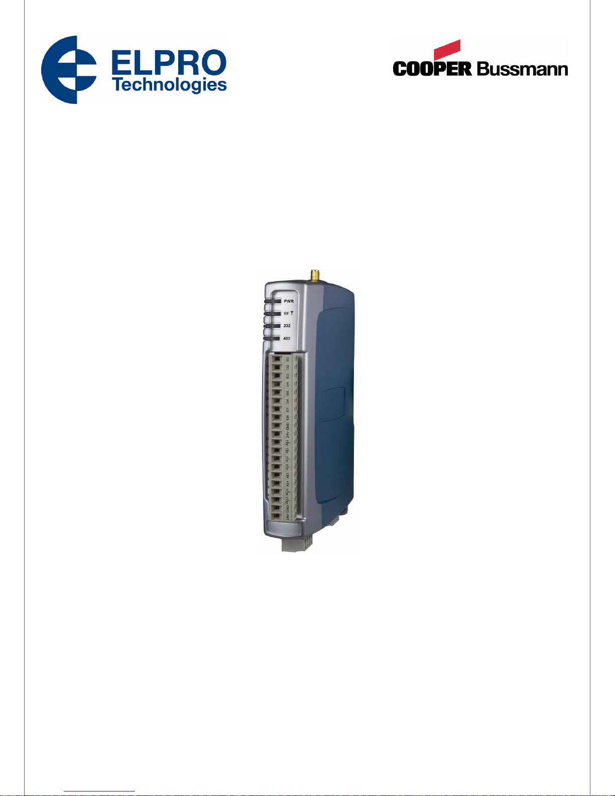
915U-2 Wireless I/O
User Manual
ELPRO Technologies, 9/12 Billabong Street, Stafford Qld, 4053 Australia.
Tel: +61 7 33528600 Fax: +61 7 33528677 Email: [email protected]
Web: www.elprotech.com
ELPRO Support Help-line America (866) 7134409 Rest of the world +617 3352 8624
V1.0.34
Page 2
915U-2 Wireless I/O Page 1
Thank you for your selection of the 915U-2 I/O Module. We trust it will give you many years
of valuable service.
Incorrect termination of supply wires may cause internal damage and will void warranty. To
ensure your 915U-2 module enjoys a long life, double check ALL your connections with the
user manual before turning the power on.
To comply with FCC RF Exposure requirements in section 1.1310 of the FCC Rules,
antennas used with this device must be installed to provide a separation distance of at
least 20 cm from all persons to satisfy RF exposure compliance.
Avoid:
ATTENTION!
CAUTION:
Operating ELPRO the transmitter when someone is within 20 cm of the antenna
Operating the transmitter unless all RF connectors are secure and any open
connectors are properly terminated
Operating the equipment near electrical blasting caps or in an explosive atmosphere
All equipment must be properly grounded for safe operations.
All equipment should be serviced only by a qualified technician
SAFETY Notice:
Exposure to RF energy is an important safety consideration. The FCC has adopted a
safety standard for human exposure to radio frequency electromagnetic energy emitted by
FCC regulated equipment as a result of its actions in Docket 93-62 and OET Bulletin 65
Edition 97-01.
Page 1 915U-2 Wireless I/O
Page 3
915U-2 Wireless I/O Page 2
GNU Free Documentation Licence:
Copyright (C) 2009 ELPRO Technologies.
ELPRO Technologies is using a part of Free Software code under the GNU General Public
License in operating the “915U-2” product. This General Public License applies to most of
the Free Software Foundation’s code and to any other program whose authors commit by
using it. The Free Software is copyrighted by Free Software Foundation, Inc. and the
program is licensed “As is” without warranty of any kind. Users are free to contact ELPRO
Technologies at the following Email Address:[email protected] for instructions on how
to obtain the source code used for the 905U-2.
A copy of the license is included in Appendix F: “GNU Free Document Licence”.
Page 2 915U-2 Wireless I/O
Page 4
915U-2 Wireless I/O Page 3
This 915U-2 module uses the “E2_900M Wireless Data Modem” radio and complies with
Part 15.247 of the FCC Rules.
Operation is subject to the following two conditions:
This device may not cause harmful interference and must accept any interference received,
including interference that may cause undesired operation.
This device must be operated as supplied by ELPRO. Any changes or modifications made
to the device without the written consent of ELPRO may void the user’s authority to operate
the device.
This device must be installed by professional installers in compliance with 47 CFR Part 15
Subpart C Section 15.204 and 15.205, who will be responsible for maintaining EIRP no
greater than 36 dBm in accordance with 47 CFR Part 15 Subpart C Section 15.247 (b)(2)(4).
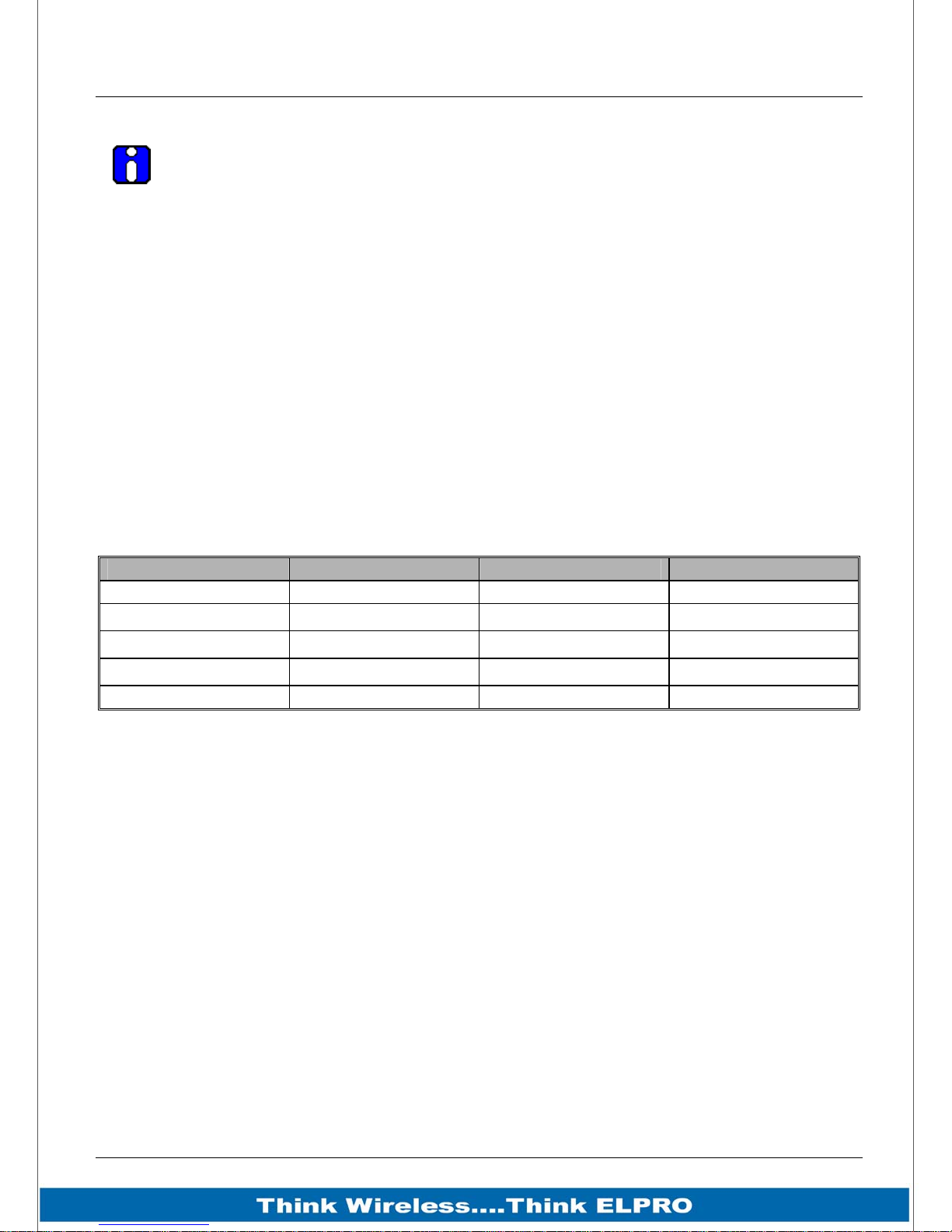
In accordance with 47 CFR Part 15 Subpart C Section 15.204 only the following
antenna/coax cable kits can be used.
FCC Notice:
Manufacturer Model Number Coax Kit Net
ELPRO SG-900-6 CC10/900 5dBi Gain
ELPRO SG-900-6 CC20/900 2dBi Gain
ELPRO SG-900EL CC10/900 2dBi Gain
ELPRO SG-900EL CC20/900 -1dBi Loss
ELPRO YU6/900 CC20/900 4dBi Gain
Part 15 –This device has been tested and found to comply with the limits for a Class
A digital device, pursuant to Part15 of the FCC rules (Code of Federal Regulations
47CFR Part 15). Operation is subject to the condition that this device does not cause
harmful interference.
Notice Any changes or modifications not expressly approved by ELPRO could void
the user’s authority to operate this equipment.
This Device should only be connected to PCs that are covered by either FCC DoC or are
FCC certified.
Page 3 915U-2 Wireless I/O
Page 5

915U-2 Wireless I/O Page 4
ELPRO products are designed to be used in industrial environments, by experienced
industrial engineering personnel with adequate knowledge of safety design considerations.
ELPRO radio products are used on unprotected license-free radio bands with radio noise
and interference. The products are designed to operate in the presence of noise and
interference, however in an extreme case, radio noise and interference could cause product
operation delays or operation failure. Like all industrial electronic products, ELPRO products
can fail in a variety of modes due to misuse, age, or malfunction. We recommend that users
and designers design systems using design techniques intended to prevent personal injury
or damage during product operation, and provide failure tolerant systems to prevent
personal injury or damage in the event of product failure. Designers must warn users of the
equipment or systems if adequate protection against failure has not been included in the
system design. Designers must include this Important Notice in operating procedures and
system manuals.
These products should not be used in non-industrial applications, or life-support systems,
without consulting ELPRO first.
IMPORTANT Notice:
A radio license is not required in some countries, provided the module is installed
using the aerial and equipment configuration described in the 915U-2 Installation
Guide. Check with your local distributor for further information on regulations.
Operation is authorized by the radio frequency regulatory authority in your country on
a non-protection basis. Although all care is taken in the design of these units, there is
no responsibility taken for sources of external interference. Systems should be
designed to be tolerant of these operational delays.
To avoid the risk of electrocution, the aerial, aerial cable, serial cables and all
terminals of the 915U-2 module should be electrically protected. To provide maximum
surge and lightning protection, the module should be connected to a suitable earth
and the aerial, aerial cable, serial cables and the module should be installed as
recommended in the Installation Guide
To avoid accidents during maintenance or adjustment of remotely controlled
equipment, all equipment should be first disconnected from the 915U-2 module
during these adjustments. Equipment should carry clear markings to indicate remote
or automatic operation. E.g. "This equipment is remotely controlled and may start
without warning. Isolate at the switchboard before attempting adjustments."
The 915U-2 module is not suitable for use in explosive environments without
additional protection.
The 915U-2 operates unlicensed Radio frequencies and proprietary protocols to
communicate over the radio. Nevertheless, if your system is not adequately secured,
third parties may be able to gain access to your data or gain control of your
equipment via the radio link. Before deploying a system make sure you have
considered the security aspects of your installation carefully.
Page 4 915U-2 Wireless I/O
Page 6

915U-2 Wireless I/O Page 5
Limited Lifetime Warranty, Disclaimer, and Limitation of
Remedies
ELPRO products are warranted to be free from manufacturing defects for the “serviceable
lifetime” of the product. The “serviceable lifetime” is limited to the availability of electronic
components. If the serviceable life is reached in less than three years following the original
purchase from ELPRO, ELPRO will replace the product with an equivalent product if an
equivalent product is available.
This warranty does not extend to:
Failures caused by the operation of the equipment outside the particular product's
specification, or
Use of the module not in accordance with this User Manual, or
Abuse, misuse, neglect or damage by external causes, or
Repairs, alterations, or modifications undertaken other than by an authorized Service
Agent.
ELPRO liability under this warranty is limited to the replacement or repair of the product.
This warranty is in lieu of and exclusive of all other warranties. This warranty does not
indemnify the purchaser of products for any consequential claim for damages or loss of
operations or profits and ELPRO is not liable for any consequential damages or loss of
operations or profits resulting from the use of these products. ELPRO is not liable for
damages, losses, costs, injury or harm incurred as a consequence of any representations,
warranties or conditions made by ELPRO or its representatives or by any other party, except
as expressed solely in this document.
Page 5 915U-2 Wireless I/O
Page 7

915U-2 Wireless I/O Page 6
TABLE OF CONTENTS
INTRODUCTION .................................................................................................................11
1.1 Overview ......................................................................................................................................................11
1.2 Module Structure.........................................................................................................................................13
1.3 Getting Started ............................................................................................................ ................................14
CHAPTER 2 - INSTALLATION........................................................................................... 15
2.1 General.........................................................................................................................................................15
2.2 Power/Supply...............................................................................................................................................15
2.2.1 Requirements.........................................................................................................................................15
2.2.2 Expansion I/O Supply ............................................................................................................................17
2.2.3 Internal I/O .............................................................................................................................................17
2.2.4 Grounding..............................................................................................................................................18
2.3 Radio ............................................................................................................................................................19
2.3.1 900 MHz Spread Spectrum radio ..........................................................................................................19
2.3.2 Meshing capability .................................................................................................................................19
2.4 Antenna........................................................................................................................................................20
Dipole and Collinear antennas...................................................................................................................22
Yagi antennas.............................................................................................................................................23
2.5 Connections.................................................................................................................................................24
2.5.1 Bottom panel connections .....................................................................................................................24
Ethernet port...............................................................................................................................................24
USB Device Port for configuration..............................................................................................................24
RS-232 port ................................................................................................................................................24
RS-485 port with Modbus Support.............................................................................................................25
2.5.2 Side Access Configuration Panel ..........................................................................................................25
“Factory Boot” switch..................................................................................................................................25
USB Host port.............................................................................................................................................26
Dipswitches.................................................................................................................................................26
Front panel connections.............................................................................................................................27
2.5.3 Digital Inputs..........................................................................................................................................28
2.5.4 Pulsed Inputs.........................................................................................................................................29
2.5.5 Digital Outputs (Pulsed Outputs)...........................................................................................................30
Digital Output Fail Safe Status ...................................................................................................................30
2.5.6 Analog Inputs.........................................................................................................................................32
Differential Current Inputs (AIN 1 & 2 only)................................................................................................32
Single Ended Current Inputs (AIN 3 & 4 only)............................................................................................33
Single Ended Voltage Inputs......................................................................................................................34
2.5.7 Analog Outputs......................................................................................................................................35
CHAPTER 3 - OPERATION................................................................................................ 36
3.1 Overview ......................................................................................................................................................36
Page 6 915U-2 Wireless I/O
Page 8

915U-2 Wireless I/O Page 7
3.2 Indications ...................................................................................................................................................36
3.2.1 Front Panel Indications..........................................................................................................................36
3.2.2 Boot Sequence “PWR” LED Indications................................................................................................36
3.2.3 Input / Output Indications.......................................................................................................................37
Digital Inputs...............................................................................................................................................37
Digital Outputs............................................................................................................................................37
Analog Inputs..............................................................................................................................................37
Analog Outputs...........................................................................................................................................37
3.2.4 Ethernet Indications...............................................................................................................................38
3.3 System Design.............................................................................................................................................39
3.3.1 Radio Channel Capacity........................................................................................................................39
Dual Band Operation..................................................................................................................................39
3.3.2 Radio Path Reliability.............................................................................................................................39
3.3.3 Design for Failures.................................................................................................................................40
3.3.4 Indicating a Communications Problem..................................................................................................41
Fail-to-transmit alarm..................................................................................................................................41
Fail-to-receive alarm...................................................................................................................................41
3.3.5 Testing and Commissioning ..................................................................................................................41
3.4 WIBMesh......................................................................................................................................................42
CHAPTER 4 - CONFIGURATION....................................................................................... 43
4.1 Module Configuration.................................................................................................................................43
4.2 First time Configuration .............................................................................................................................44
4.2.1 Default IP Address.................................................................................................................................44
4.2.2 Accessing Configuration........................................................................................................................44
4.2.3 Power up the 915U-2 module................................................................................................................45
4.2.4 Over the Air Web Based Configuration .................................................................................................47
4.3 Module Information Web Page...................................................................................................................48
4.4 System Tools Web page.............................................................................................................................49
System Log File..........................................................................................................................................49
Reading Configuration File.........................................................................................................................49
Writing Configuration File...........................................................................................................................49
Firmware Upgrade – Web Page.................................................................................................................49
Firmware Upgrade – USB ..........................................................................................................................49
4.5 Feature Licence Keys Web Page...............................................................................................................51
4.6 Address Map................................................................................................................................................51
4.6.1 Standard 915U-2 I/O (Basic I/O)............................................................................................................52
4.7 Serial Expansion I/O....................................................................................................................................52
4.7.1 Adding modules.....................................................................................................................................52
4.7.2 115S Expansion I/O Memory Map.........................................................................................................53
CHAPTER 5 - DIAGNOSTICS.............................................................................................54
5.1 IO Diagnostics.............................................................................................................................................54
5.1.1 Modbus Error Registers.........................................................................................................................55
5.2 Connectivity.................................................................................................................................................55
Page 7 915U-2 Wireless I/O
Page 9

915U-2 Wireless I/O Page 8
LQI (Link Quality Indication).......................................................................................................................56
5.3 Network Diagnostics...................................................................................................................................57
Ping.............................................................................................................................................................57
Trace Route................................................................................................................................................58
5.4 Network Statistics.......................................................................................................................................59
5.5 Monitor Radio Comms................................................................................................................................61
5.6 Statistics ......................................................................................................................................................63
CHAPTER 6 - SPECIFICATIONS .......................................................................................64
6.1 Specifications..............................................................................................................................................64
APPENDIX A: DBM TO MW CONVERSION TABLE.......................................................66
APPENDIX B: I/O STORE REGISTERS .......................................................................... 67
“Output Coils”..................................................................................................................................................67
“Input Bits”.......................................................................................................................................................67
“Input Registers” .............................................................................................................................................68
“Holding Registers”.........................................................................................................................................69
APPENDIX C: EXPANSION I/O STORE REGISTERS .................................................... 70
I/O store for a 115S-11 Expansion I/O module...............................................................................................71
I/O store for a 115S-12 Expansion I/O module...............................................................................................72
I/O store for a 115S-13 Expansion I/O module...............................................................................................73
APPENDIX D: MODBUS ERROR CODES.......................................................................74
APPENDIX E: WEB PAGE CONFIGURATION................................................................75
Network Configuration .....................................................................................................................................75
Mesh ...................................................................................................................................................................77
IP Routing ..........................................................................................................................................................79
Radio Settings...................................................................................................................................................80
Mesh Fixed Routes............................................................................................................................................81
Example #1.....................................................................................................................................................81
Example #2.....................................................................................................................................................82
WIBMesh Configuration ...................................................................................................................................83
WIBMesh Mappings ..........................................................................................................................................85
Write Mappings (Writing Local I/O to remote I/O)...........................................................................................85
Read Mappings (Read remote I/O and storing it locally)................................................................................87
Gather/Scatter Write Mappings ......................................................................................................................88
Sensitivity Block..............................................................................................................................................89
Page 8 915U-2 Wireless I/O
Page 10

915U-2 Wireless I/O Page 9
915U-2 Module I/O Registers.........................................................................................................................90
115S Serial Expansion Modules I/O Registers...............................................................................................91
Fail Safe Configuration.....................................................................................................................................93
“Invalid” register state .....................................................................................................................................93
Fail Safe Blocks ..............................................................................................................................................94
Serial Configuration..........................................................................................................................................95
Modbus TCP to RTU Gateway.......................................................................................................................95
Expansion I/O .................................................................................................................................................97
I/O Configuration...............................................................................................................................................98
Analog Inputs..................................................................................................................................................99
Calculating Span ......................................................................................................................................100
Calculating Zero .......................................................................................................................................100
Analog Outputs.............................................................................................................................................101
Digital Input...................................................................................................................................................102
Digital Output ................................................................................................................................................102
Pulsed Outputs .............................................................................................................................................103
Modbus TCP Transfer.....................................................................................................................................103
Modbus TCP Configuration......................................................................................................................106
Modbus TCP Mappings............................................................................................................................107
APPENDIX F: GNU FREE DOCUMENT LICENCE........................................................ 108
Page 9 915U-2 Wireless I/O
Page 11

Page 10 915U-2 Wireless I/O
TABLE OF FIGURES
Figure 1 – Module Structure ..................................13
Figure 36 – Trace Route.........................................58
Figure 2 – Power Connectors................................ 15
Figure 3 – Supply Connections..............................15
Figure 4 – Expansion I/O power & RS485............. 17
Figure 5 - Earthing .................................................18
Figure 6 -Wrapping Coax Connections.................. 21
Figure 7 – Collinear Antenna mounting ................. 22
Figure 8 - Yagi Antenna Mounting......................... 23
Figure 9 – Bottom Panel Connections................... 24
Figure 10 – RS485 Connections............................25
Figure 11 – Side Access Panel..............................25
Figure 12 – Front Panel Connections.................... 27
Figure 13 – Digital Input Wiring.............................. 28
Figure 14 – Pulsed Input Wiring............................. 29
Figure 15 – Digital Output Wiring...........................30
Figure 16 – Digital Output Failsafe Times .............31
Figure 17 - Fail-Safe State..................................... 31
Figure 18 – Differential Current Inputs................... 32
Figure 37 – Network Statistics Period ....................59
Figure 38 – Network Statistics................................59
Figure 39 – Hourly Statistics...................................60
Figure 40 –Daily/Weekly Statistics .........................60
Figure 41 - Monitor Comms....................................61
Figure 42 – Module Statistics .................................63
Figure 43 – Network Configuration Screen ............75
Figure 44 - Mesh Configuration..............................77
Figure 45 - IP Routing.............................................79
Figure 46 – Radio Configuration Screen................80
Figure 47 - Mesh Fixed Route #1...........................81
Figure 48 - Mesh Fixed Route#2 Routing Rules ....81
Figure 49 - Mesh Fixed Route #2...........................82
Figure 50 – Mesh Fixed Route #2 Routing Rules...82
Figure 51 – WIBMesh Configuration Screen..........83
Figure 52 – WIBMesh Mappings ............................85
Figure 53 – Write Mappings....................................85
Figure 19– Single Ended Current Inputs ...............33
Figure 20 – Voltage Inputs..................................... 34
Figure 21 – Analog Outputs................................... 35
Figure 22 - Boot Sequence.................................... 36
Figure 23 - Installation............................................ 43
Figure 24 – Configuration Software....................... 43
Figure 25 – Network Settings................................. 45
Figure 26 - Ping...................................................... 45
Figure 27 – Main Welcome Screen........................ 46
Figure 28 -Over the air Configuration .................... 47
Figure 29 – Module Information............................. 48
Figure 30 – System Tools...................................... 49
Figure 31 - Firmware Upgrade LED Indications ....50
Figure 32 - Feature License Keys..........................51
Figure 33- I/O Diagnostics..................................... 54
Figure 34 - Connectivity......................................... 55
Figure 35 – Network Diagnostics........................... 57
Figure 54 – Read Mappings ...................................87
Figure 55 – Gather/Scatter Mappings ....................88
Figure 56 – Sensitivity Block...................................89
Figure 57- Invalid Register State............................93
Figure 58 – Fail Safe Blocks...................................94
Figure 59– Serial Port Configuration ......................95
Figure 60 – Modbus TCP to RTU...........................96
Figure 61 – I/O Configuration .................................98
Figure 62 – Analog Input Configuration..................99
Figure 63 – Analog Output Configuration............ 101
Figure 64 – Digital Input Configuration................ 102
Figure 65 – Digital Output Configuration............. 102
Figure 66 – Pulsed Output Configuration............ 103
Figure 67 - Modbus Server.................................. 104
Figure 68 - Modbus Client ................................... 104
Figure 69 - Modbus TCP Client Mappings .......... 105
Page 10 915U-2 Wireless I/O
Page 12

915U-2 Wireless I/O Page 11
Introduction
1.1 Overview
The 915U-2 range of I/O modules has been designed to provide standard “off-the-shelf”
telemetry functions, for an economic price. Telemetry is the transmission of data or
signals over a long distance via radio or twisted-pair wire cable.
Although the 915U-2 Series is intended to be simple in its application, it provides many
sophisticated features, which will be explained in the following chapters.
This manual should be read carefully to ensure that the modules are configured and
installed to give reliable performance.
The 915U-2 telemetry module extends the functionality provided by the earlier 105U and
905U E-series modules. It provides on-board I/O via a front mounting 20-way connector
and has provision for extra expansion modules (ELPRO 115S or MODBUS devices) to
be connected using a standard RS485 serial connection.
The module can monitor the following types of signals
Digital (on/off) signals - Contact Closure or Switch
Analog (continuously variable) signals – Tank level, Motor speed, temperature,
etc
Pulsed signal - Frequency signal – Metering, accumulated total, rainfall, etc
Internal Signals – Supply voltage, Supply failure, battery status, etc.
The modules monitor the input signals and transmit the values by radio or Ethernet
cabling to another module or modules that have been configured to receive this
information.
The 915U-2 radio has been designed to meet the requirements of unlicensed operation
for remote monitoring and control of equipment. A radio licence is not required for the
915U-2 in many countries.
Input signals that are connected to the module are transmitted and appear as output
signals on other modules. A transmission occurs whenever a "Change-of-State”, “COS”
occurs on an input signal. A "Change-of-State" of a digital or an internal digital input is a
change from "off" to "on" or vice-versa.
For an analog input, internal analog input or pulse input rate a "Change-of-State" is a
configurable value called “Sensitivity”. The default Sensitivity is 1000 counts (3%) but
can be changed in the Sensitivity Block page.
In addition to change-of-state messages, update messages are automatically
transmitted on a configurable time basis. This update ensures the integrity of the
system.
Pulse inputs counts are accumulated and the total count is transmitted regularly
according to the configured update time.
The 915U-2 modules transmit the input/output data using radio or Ethernet. The data
frame includes the "address" of the transmitting module and the receiving module, so
Page 11 915U-2 Wireless I/O
Page 13

Page 12 915U-2 Wireless I/O
that each transmitted message is acted on only by the correct receiving unit. Each
message includes error checking to ensure that no corruption of the data frame has
occurred due to noise or interference. The module with the correct receiving "address"
will acknowledge the message with a return transmission (acknowledgement). If the
original module does not receive a correct acknowledgement, it will retry 1 to 5 times
(default is 3) before setting the communications fail status of that message. For critical
messages, this status can be reflected on an output on the module for alert purposes.
The module will continue to try to establish communications and retry, each time an
update, or change-of-state occurs.
A system can be a complex network or a simple pair of modules. An easy-to-use
configuration procedure allows the user to specify any output destination for each input.
Two versions of the 915U-2 are available. The Legacy version provides operation with
existing ELPRO wireless I/O devices (905 series and 105 series modules). The second
version provides enhanced features, including IP addressing, allowing thousands of
modules to exist in a system, and allowing automatic routing of messages through
repeater stations.
Each 915U-2 radio can have up to 24 expansion I/O modules (ELPRO 115S) connected
by RS485 twisted pair provided there is sufficient power to power all modules with I/O.
Any input signal at any module may be configured to appear at any output on any
module in the entire system.
Modules can be used as repeaters to re-transmit messages on to the destination
module. Repeaters can repeat messages on the radio channel or from the radio
channel to the serial channel (and serial to radio). Using Legacy protocol, up to five
repeater addresses may be configured for each input-to-output link. The meshing
protocol will automatically select other stations to act as repeaters if required.
The units may be configured via ethernet using a web browser or via USB port and
system configuration software. The web based configuration and software configuration
is defined in Chapter 4 - Configuration.
Page 12 915U-2 Wireless I/O
Page 14
915U-2 Wireless I/O Page 13
1.2 Module Structure
915U-2
On Board I/O
8 x DIO
2 x DIFF AIN
2 x Single Ended AIN
2 X AOT
Various Internal I/O
I/O Expansion Port
Ethernet Port
IO STORE
Discrete Outputs (00001)
Discrete Inputs (10001)
Word Inputs (30001)
Word Outputs (40001)
Long Inputs (36001)
Float Inputs (38001)
Long Outputs (46001)
Float Outputs (48001)
Figure 1 – Module Structure
RADIO INTERFACE
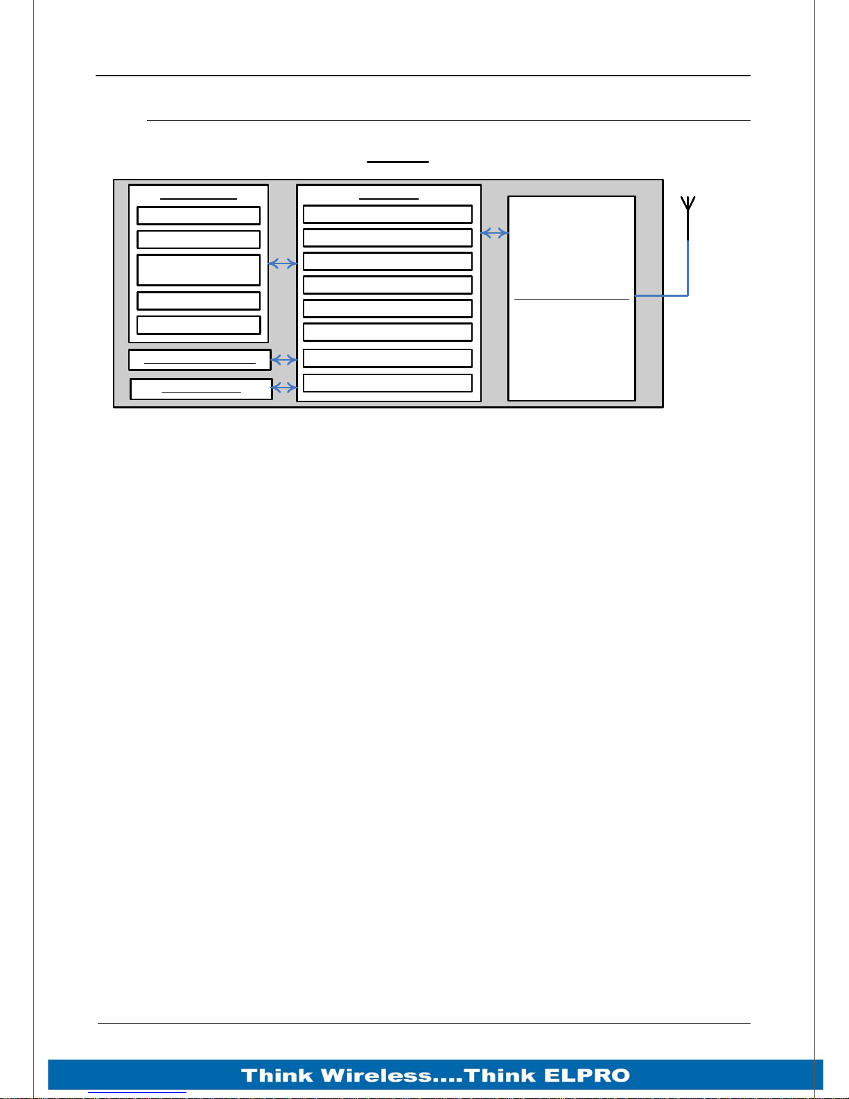
The 915U-2 is made up of a number of basic sections, which all interface with a central
Input and output storage area (I/O Store).
The I/O Data Store provides storage for I/O data as well as providing services to other
processes in the system. The I/O Store provides eight different blocks of data - two
containing input and output bit data, two containing input and output word data, two
containing long-word type data and two containing floating-point data. The two files of
each type in turn support inputs and outputs on the local machine, and data storage for
the gateway function of the machine. These files are mapped into the address map as
described below. There are other registers values within the database that can be used
for system management - these will be discussed later in this manual.
The Radio Interface allows the 915U-2 to communicate with other modules within the
system using a proprietary radio protocol called “WIBMesh”. Messages from other
915U-2 modules are received by the radio port and used to update the input values in
the I/O Data Store. The WIBMesh protocol is an extremely efficient protocol for radio
communications. Radio messages can be sent using exception reporting - that is, when
there is a change of an input signal - or by read/write messages. Each message will be
comprised of multiple I/O values termed as a “block” of I/O). There are also update
messages, which are sent for integrity purposes. Messages include error checking, with
the destination address sending a return acknowledgment. Up to four attempts are
made to transmit the message over each hop of the radio path, if no acknowledgement
is received. The WIBMesh protocol is designed to provide reliable radio communications
on an open license-free radio channel.
The On-Board I/O in the form of - 8 discrete I/O, 2 single ended analog inputs, 2
differential analog inputs, and 2 current sourcing analog outputs. Each discrete I/O can
function as either a discrete input (voltage free contact input) or discrete output
(transistor output). Each I/O point is linked to separate I/O registers within the I/O Data
Store.
Page 13 915U-2 Wireless I/O
Page 15

Page 14 915U-2 Wireless I/O
There are also a number of Internal I/O that can be accessed from the I/O Data Store.
These inputs can be used to interpret the status of a single module or an entire system
Battery voltage – The battery terminal voltage displayed as an Analog value.
Loop Supply – Monitors the +24V DC Analog Loop Supply (ALS), used to power
analog current loops and displays this as an Analog value.
Expansion Module Volts – Monitors the Supply voltage of the connected
expansion modules, displayed as an Analog value.
RSSI – Will indicate the radio signal level for the selectable address, displayed as
a dB level. Note: Only available in Legacy version. Otherwise, refer to
Communication diagnostics functions
Comms Fail – A selectable register can indicate a Communications fail for the
selected address. Note: Only available in Legacy version. Otherwise, refer to
Communication diagnostics functions
Lastly, the Expansion port, which enables 115S expansion I/O modules to be added to
the module. Expansion module I/O is dynamically added to the I/O of the 915U-2 by
adding an offset to the address.
1.3 Getting Started
Most applications for the 915U-2 require little configuration. The 915U-2 has many
sophisticated features, however if you do not require these features, this section will
allow you to configure the units quickly.
First, read Chapter 2 - , “Installation”, which will go through the power supply,
antenna/coax connections and any I/O connections.
Power the 915U-2 and make an Ethernet connection to your PC (refer to Section 4.2
“First time Configuration”)
Set the 915U-2 address settings as per Section 0 ”Network Configuration”
Save the configuration and the 915U-2 module is now ready to use.
Page 14 915U-2 Wireless I/O
Page 16
915U-2 Wireless I/O Page 15
Chapter 2 - Installation
2.1 General
All 915U-2 Series modules are housed in a plastic enclosure with DIN rail mounting,
providing options for up to 12 I/O points, and separate power & communications
connectors. The enclosure measures 170 x 150 x 33 mm including connectors. The
antenna protrudes from the top
2.2 Power/Supply
Figure 2 – Power Connectors
External “Sealed Lead
Acid” battery if required
_
+
15-30V DC Supply
Figure 3 – Supply Connections
POWER SUPPLY
GND
BAT +
SUP SUP +
2.2.1 Requirements
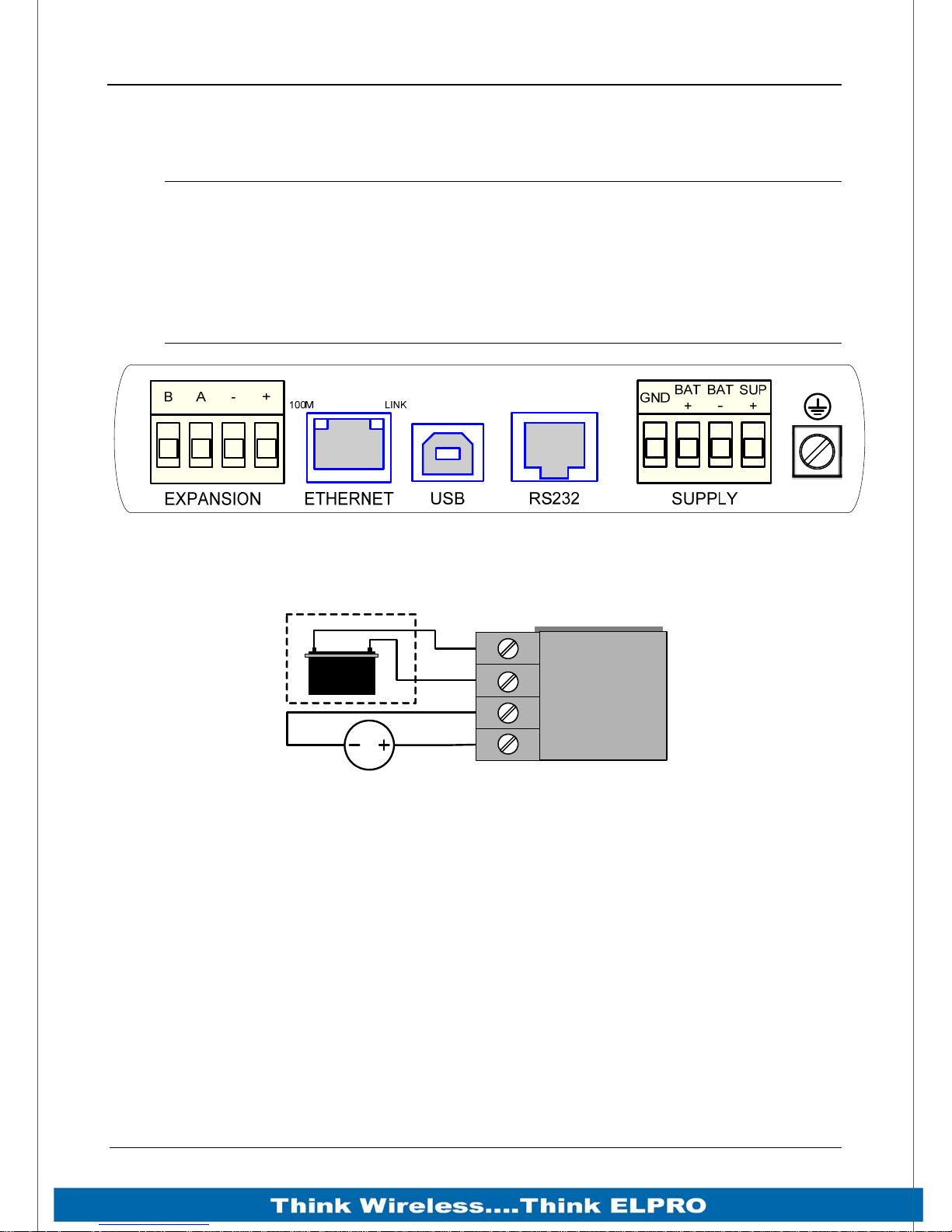
The 915U-2 power supply is a switch-mode supply and will accept a 15 - 30 volt DC
power source connected to the “Sup + & Sup -” terminals.
Both Supply and Battery connections have reverse polarity and over voltage protection.
If powered from the “Sup + & Sup -” terminals the Power Supply must be able to supply
enough current to power all operations, e.g. Module Quiescent current, Peak Transmit
current, Digital and Analog I/O including loop supply, Battery charging (if applicable),
etc.
The recommended “Supply” power source is +24VDC 2Amp (+12VDC 4Amp).
The module can be operated primarily from the supply terminals or in conjunction with a
battery connected to the “BAT + & GND” terminals.
Page 15 915U-2 Wireless I/O
Page 17
Page 16 915U-2 Wireless I/O
If a backup battery is used then the module Supply can have a lower current rating as
the Peak current will be supplied by the battery.
To calculate the Power Supply current limit, use the following criteria.
Quiescent Current of the module is 200mA.
Module I/O total is 500mA
Peak Transmit current is 500mA
External Expansion I/O connected is 1000mA Max
Battery charging is 1000mA (Internally limited)
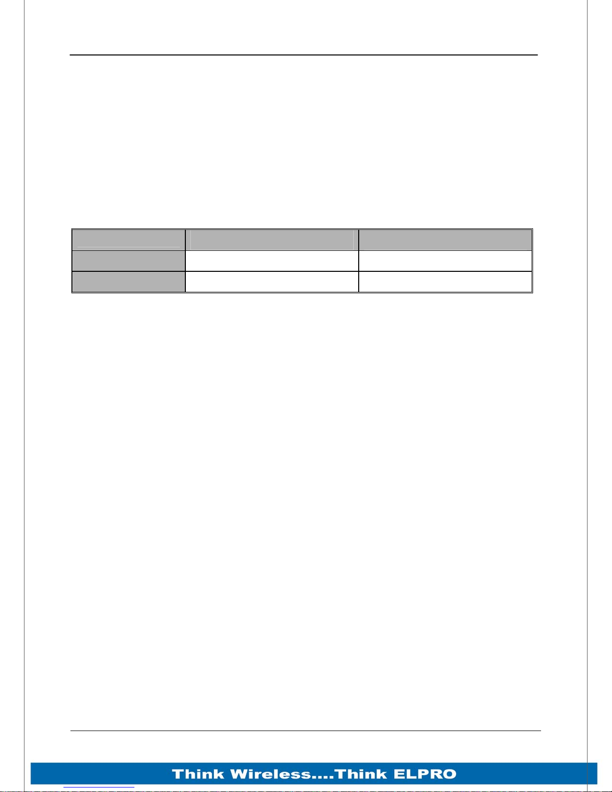
The following table represents the Supply current limit for different requirements
No Battery fitted
Battery fitted
Expansion I/O No Expansion I/O
2200mA 1200 mA
2700 mA 1700 mA
E.g. If there is a battery connected and no expansion I/O the minimum current needed
is 1.7Amps @13.8V this is because the battery will provide peak current during radio
transmissions.
If a backup battery is not connected and I/O modules are required and then the
minimum current needed will be approximately 2.2Amps @13.8V.
This is allowing for 500mA Peak Transmit current and up to 1 amp for expansion I/O
The power supply should be CSA Certified Class 2 approved for normal operation and if
being used in Class I Div 2 explosive areas, the power supply must have a Class I Div 2
approval.
The power supply automatically charges a 13.8V Sealed Lead-Acid battery connected
to the “BAT+” and “GND” terminals at up to 1A.
The power supply input and battery charging are hosted on a 4-way terminal on the
bottom edge of the module labelled “Supply”.
Page 16 915U-2 Wireless I/O
Page 18
915U-2 Wireless I/O Page 17
2.2.2 Expansion I/O Supply
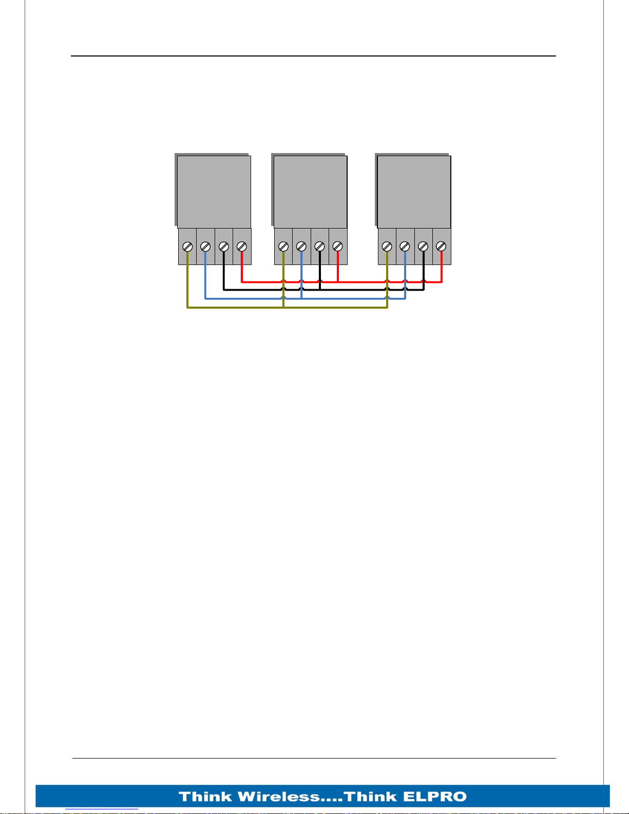
To allow increased I/O Capacity, a second 4-way terminal labelled “Expansion I/O”
provides a +12 Volt supply (up to 1A) and RS485 communications for any 115S serial
expansion I/O modules.
B
915U-2
-
A
+
115S- XX
B
A
115S- XX
-
+
B
-
A
+
Figure 4 – Expansion I/O power & RS485
As a guide when using the I/O power connection from the 915U-2, the number of I/O
modules is limited to three 115S-11 (using inputs), one 115S-12, or one 115S-13.
If more I/O Modules are required, you will need to calculate the overall current
consumption using the following criteria and power the modules from an external
supply.
115S Module Static Current drain = 120mA
115S Digital Inputs require 13mA per active input
115S Digital Outputs require 25mA per active output
115S Analog Inputs and Outputs require 50mA per I/O when operating at 20mA
E.g. a single 115S-11 using inputs only has a current consumption of approximately
320mA so you could connect up to three 115S-11 modules to the Expansion port
without overloading the on board I/O power supply.
A single 115S-12 using all analog inputs and digital outputs has a current consumption
of approximately 720mA so you could only connect one.
Keep in mind that when calculating the current consumption for the expansion I/O, the
maximum available current from the onboard power supply is 1 Amp. If the overall
Expansion I/O current consumption is over the 1 Amp maximum an external power
source will be required. The 915U-2 provides up to 1 Amp for battery charging.
2.2.3 Internal I/O
The internal Supply voltages can be monitored by reading the Modbus locations below.
The registers can also be mapped to a register or an analog output on another module
within the radio network.
30005 Local Supply voltage (8-40V scaling)
Page 17 915U-2 Wireless I/O
Page 19
Page 18 915U-2 Wireless I/O
30006 Local Battery voltage (8-40V scaling)
30007 Local 24V loop voltage (8-40V scaling) – Internally generated +24V supply
used for analog loop supply. Maximum Current limit is 150mA
30008 115S Supply Voltage (8-40V scaling)
Floating Point Registers 38005 – 38008 also indicate the Supply voltage, Battery
Voltage, +24V Supply and 115S Supply voltages but in a voltage scale.
There are no dedicated discrete low voltage alarm indicators however each supply
voltage does have a High and a low Setpoint Status which can be used for this type of
alarm.
See section 0“Analog Inputs” for details on how to configure these alarms.
2.2.4 Grounding
To provide maximum surge and lightning protection each module should be effectively
earthed / grounded via a "GND" terminal on the module – this is to ensure that the
surge protection circuits inside the module are effective. The module should be
connected to the same common ground or earth point as the enclosure “earth” and the
antenna mast “earth”.
The 915U-2 has a dedicated Earth connection screw on the bottom end plate next to
the Supply terminals. All EARTH wiring should be minimum 2mm² - 14 AWG
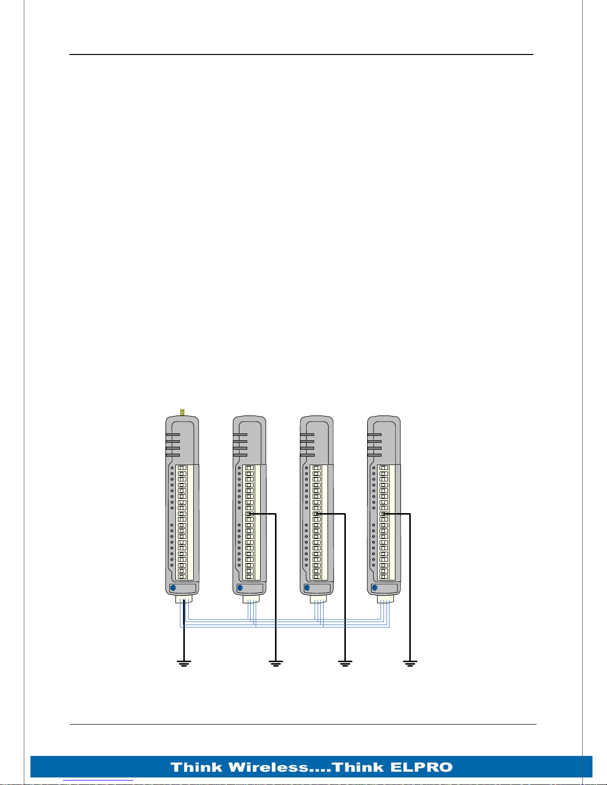
If using the 915U-2 with serial Expansion I/O modules then all expansion modules must
have a separate earth connection from the front terminal back to the common earth or
ground point. See Figure 5 below
PWR
RF
232
485
ELPRO
915U-2
PWR
OK
TX
RX
ELPRO
115S-12
PWR
OK
TX
RX
ELPRO
115S-12
PWR
OK
TX
RX
ELPRO
115S-12
Page 18 915U-2 Wireless I/O
Figure 5 - Earthing
Page 20

915U-2 Wireless I/O Page 19
2.3 Radio
The following radio variants are available in the 915U-2 dependent on the country of
operation.
2.3.1 900 MHz Spread Spectrum radio
The radio operates in the 902-928 MHz ISM band and uses frequency hopping spread
spectrum modulation, which is a method of transmitting radio signals by rapidly
switching the carrier among many frequency channels, using a pseudo random
sequence known to both transmitter and receiver as Hop Sets.
There are two Hop sets and each one uses a different pseudo random sequence of
radio channels. Each Hop Set is made up of 50 channels, which cycle through to the
next channel after each transmission. (Some countries use fewer channels, e.g. New
Zealand).
The receiver is continually scanning all channels in the hop-set and when a valid data
packet is heard, it locks on to the channel and receives the data.
A spread-spectrum transmission offers some advantages over a fixed-frequency
transmission. These are - Spread-spectrum signals are more resistant to narrowband
interference, they are difficult to intercept or eavesdrop because of the pseudorandom
transmission sequences and transmissions can share a frequency band with other
types of conventional transmissions with minimal interference.
2.3.2 Meshing capability
The ELPRO WIBMesh protocol is based on the “Ad hoc On Demand Distance Vector”
(AODV) routing algorithm which is a routing protocol designed for ad hoc networks.
AODV is capable of unicast and multicast routing and is an on demand algorithm,
meaning that it builds and maintains these routes only as long as they are needed by
the source devices.
The Protocol creates a table, which shows the connection routes to other device in the
system. The Protocol uses sequence numbers to ensure the routes are kept as current
as possible. It is loop-free, self-starting, and can scale to a large numbers of nodes.
See section 3.4 “WIBMesh” for more details on configuration.
Page 19 915U-2 Wireless I/O
Page 21

Page 20 915U-2 Wireless I/O
2.4 Antenna
The 915U-2 module will operate reliably over large distances. The distance that can be
reliably achieved will vary with each application and depend on the type and location of
antennas, the degree of radio interference, and obstructions (such as hills or trees) to
the radio path.
Typical reliable distances are detailed below, however longer distances can be achieved
if antennas are mounted in elevated locations – such as on a hill or on a radio mast.
Using the 900 MHz Spread Spectrum radio the distances achievable will be:
USA/Canada 15 miles - 6dB net gain antenna configuration permitted (4W EIRP)
Australia/NZ 12 km - Unity gain antenna configuration (1W EIRP)
To achieve the maximum transmission distance, the antennas should be raised above
intermediate obstructions so the radio path is true “line of sight”. Because of the
curvature of the earth, the antennas will need to be elevated at least 15 feet (5 metres)
above ground for paths greater than 3 miles (5 km). The modules will operate reliably
with some obstruction of the radio path, although the reliable distance will be reduced.
Obstructions that are close to either antenna will have more of a blocking effect than
obstructions in the middle of the radio path. For example, a group of trees around the
antenna is a larger obstruction than a group of trees further away from the antenna.
The 915U-2 module provides a range of test features, including displaying the radio
signal strength. Line-of-sight paths are only necessary to obtain the maximum range.
Obstructions will reduce the range however, but may not prevent a reliable path. A
larger amount of obstruction can be tolerated for shorter distances. For very short
distances, it is possible to mount the antennas inside buildings. All radio paths require
testing to determine if they are reliable - refer section 5.4 “Network Statistics” Where it
is not possible to achieve reliable communications between two modules, then a third
module may be used to receive the message and re-transmit it. This module is referred
to as a repeater. This module may also have input/output (I/O) signals connected to it
and form part of the I/O network - refer to Chapter 4 Configuration of this manual.
An antenna should be connected to the module via 50 ohm coaxial cable (e.g. RG58,
RG213, Cellfoil, etc) terminated with a male SMA coaxial connector. The higher the
antenna is mounted, the greater the transmission range will be, however as the length
of coaxial cable increases so do cable losses. For use on unlicensed frequency
channels, there are several types of antennas suitable for use. It is important antennas
are chosen carefully to avoid contravening the maximum power limit on the unlicensed
channel - if in doubt refer to an authorised service provider.
The net gain of an antenna/cable configuration is the gain of the antenna (in dBi) less
the loss in the coaxial cable (in dB).
Page 20 915U-2 Wireless I/O
Page 22
915U-2 Wireless I/O Page 21
The net gain of the antenna/cable configuration is determined by adding the antenna
gain and the cable loss. For example, a 6 element Yagi with 70 feet (20 metres) of
Cellfoil has a net gain of 4dB (10dB – 6dB).
Maximum Gain per region
Country Max Gain (dB)
USA / Canada 6
Australia / New Zealand 0
Europe 0
Typical Antenna Gains
Antenna Gain (dB)
Dipole with integral 15’ cable 0
5dBi Collinear (3dBd) 5
8dBi Collinear (6dBd) 8
6 element Yagi 10
9 element Yagi 12
16 element Yagi 15
Typical Coax losses (900 MHz)
Cable Type Loss (dB per 30ft / 10m)
RG58 -5dB
RG213 -2.5dB
CC10 (3m Cellfoil) -3dB
CC20 (6m Cellfoil) -6dB
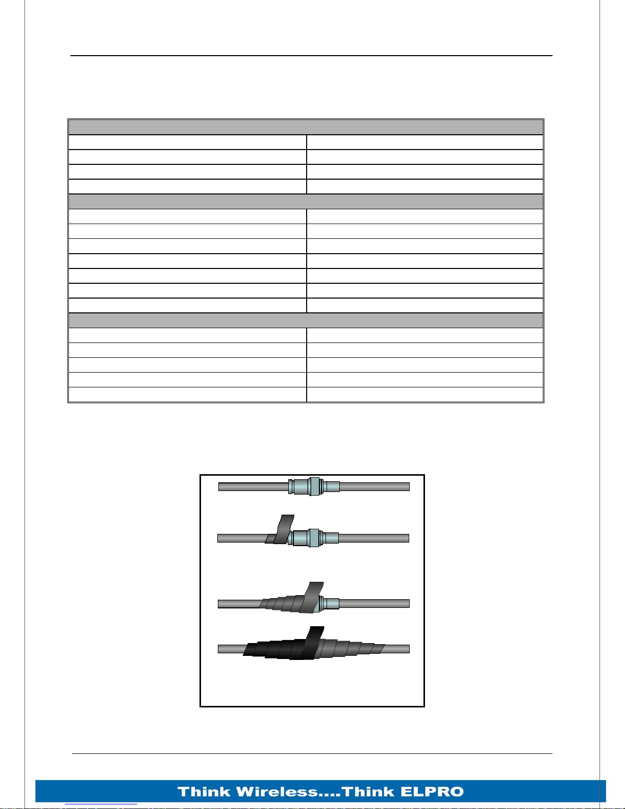
Connections between the antenna and coaxial cable should be carefully taped to
prevent ingress of moisture. Moisture ingress in the coaxial cable is a common cause
for problems with radio systems, as it greatly increases the radio losses.
Stretch to e lo n g a te s ea lant tape
while wrapping over the connection
For proper UV protection Electrical
Tape should then be wrapped over
the Vulcanising Tape
Figure 6 -Wrapping Coax Connections
Page 21 915U-2 Wireless I/O
Page 23
Page 22 915U-2 Wireless I/O
We recommend that the connection be taped, firstly with a layer of PVC Tape, then with
a vulcanising tape such as “3M 23 tape”, and finally with another layer of PVC UV
Stabilised insulating tape. The first layer of tape allows the joint to be easily inspected
when trouble shooting as the vulcanising seal can be easily removed.
Where antennas are mounted on elevated masts, the masts should be effectively
earthed to avoid lightning surges. For high lightning risk areas, surge suppression
devices between the module and the antenna are recommended. If the antenna is not
already shielded from lightning strike by an adjacent earthed structure, a lightning rod
may be installed above the antenna to provide shielding.
Dipole and Collinear antennas.
A collinear antenna transmits the same amount of radio power in all directions - and
they are easy to install and use because they do not need to be aligned to the
destination. The dipole antenna with integral 15 ‘cable does not require any additional
coaxial cable; however a cable must be used with the collinear antennas.
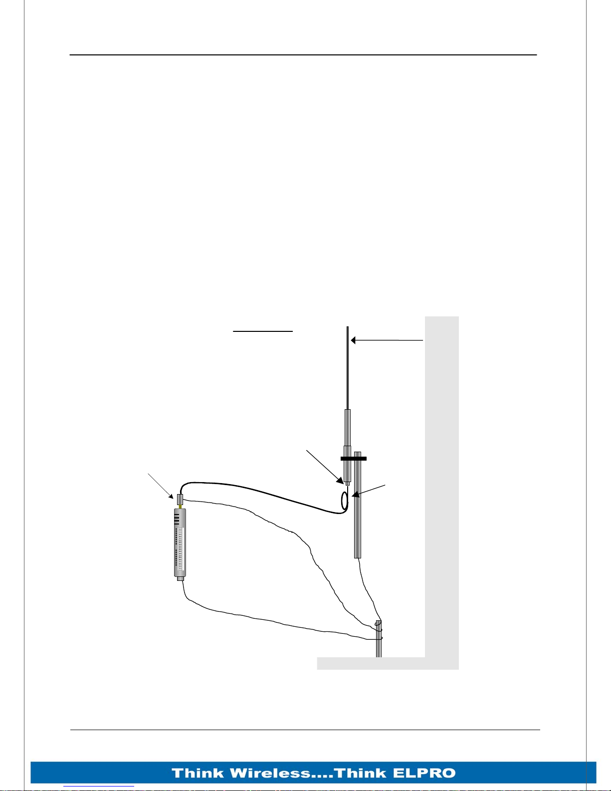
Collinear and dipole antennas should be mounted vertically, preferably 1 wavelength
away from a wall or mast to obtain maximum range.
SURGE
ARRESTOR
(OPTIONAL)
MODEM
GND
Wavelengths
150 MHz 200 cm
450 MHz 66 cm
900 MHz = 33 cm
2.4 GHz = 13 cm
5 GHz = 6 cm
WEATHERPROOF
CONNECTORS WITH
“3M 23” TAPE
COAXIAL CABLE
OK
Radio
RS232
RS485
PROVIDE GOOD GROUND
CONNECTION TO MAST,
E2
MODULE AND SURGE
ARRESTOR
1 wavelength
COLINEAR
ANTENNA
STRESS RELIEF
LOOP
MAST
IF GROUND CONDITIONS
ARE POOR, INSTALL MORE
THAN ONE STAKE
Page 22 915U-2 Wireless I/O
Figure 7 – Collinear Antenna mounting
Page 24
915U-2 Wireless I/O Page 23
Yagi antennas.
A Yagi antenna provides high gain in the forward direction, but lower gain in other
directions. This may be used to compensate for coaxial cable loss for installations with
marginal radio path.
The Yagi gain also acts on the receiver, so adding Yagi antennas at both ends of a link
provides a double improvement.
Yagi antennas are directional. That is, they have positive gain to the front of the
antenna, but negative gain in other directions.
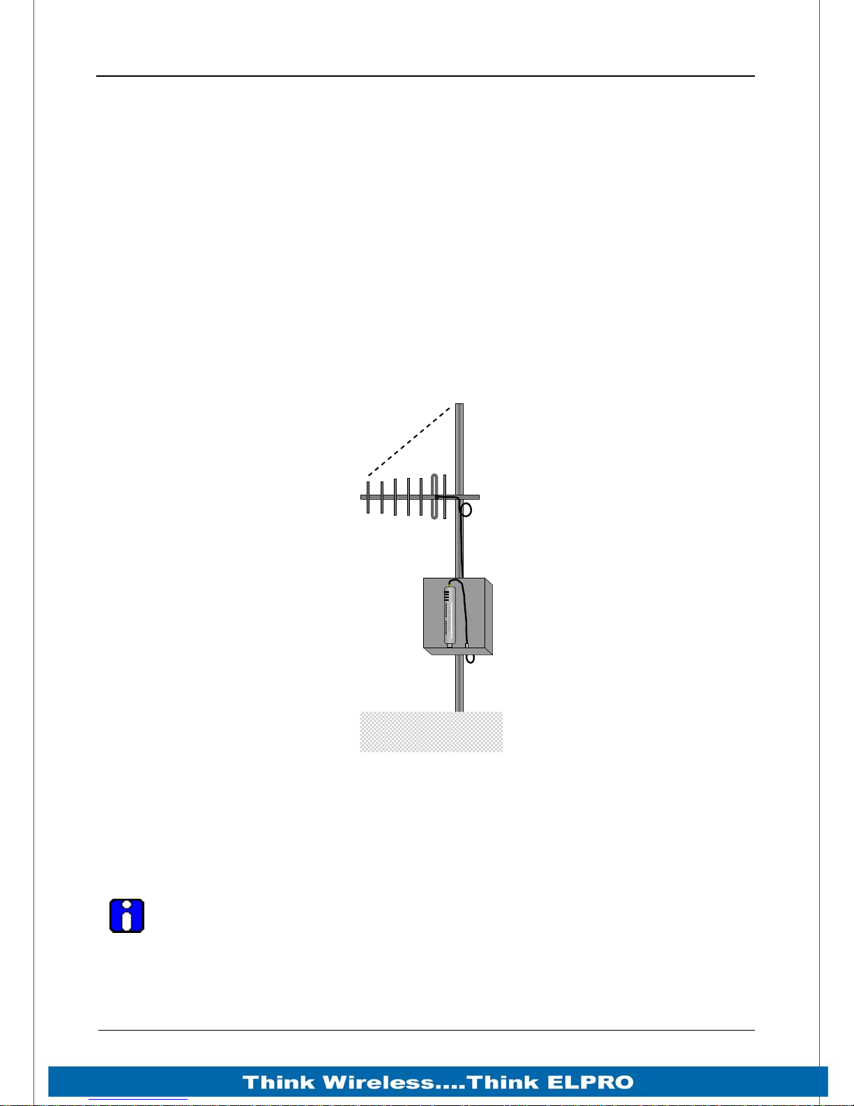
Hence, Yagi antennas should be installed with the central beam horizontal and must be
pointed exactly in the direction of transmission to benefit from the gain of the antenna.
The Yagi antennas may be installed with the elements in a vertical plane (vertically
polarised) or in a horizontal plane (horizontally polarised), however both antenna must
be in the same plane for maximum signal. If the antenna are mounted in different planes
the receive signal level will be reduced by around 30dB.
o
45
Directional
Antenna
OK
Radio
RS232
RS485
E2
Figure 8 - Yagi Antenna Mounting
For a two-station installation, with both modules using Yagi antennas, horizontal
polarisation is recommended. If there are more than two stations transmitting to a
common station, then the Yagi antennas should have vertical polarisation, and the
common (or “central” station should have a collinear (non-directional) antenna.
Note that Yagi antennas normally have a drain hole on the folded element - the
drain hole should be located on the bottom of the installed antenna.
Page 23 915U-2 Wireless I/O
Page 25
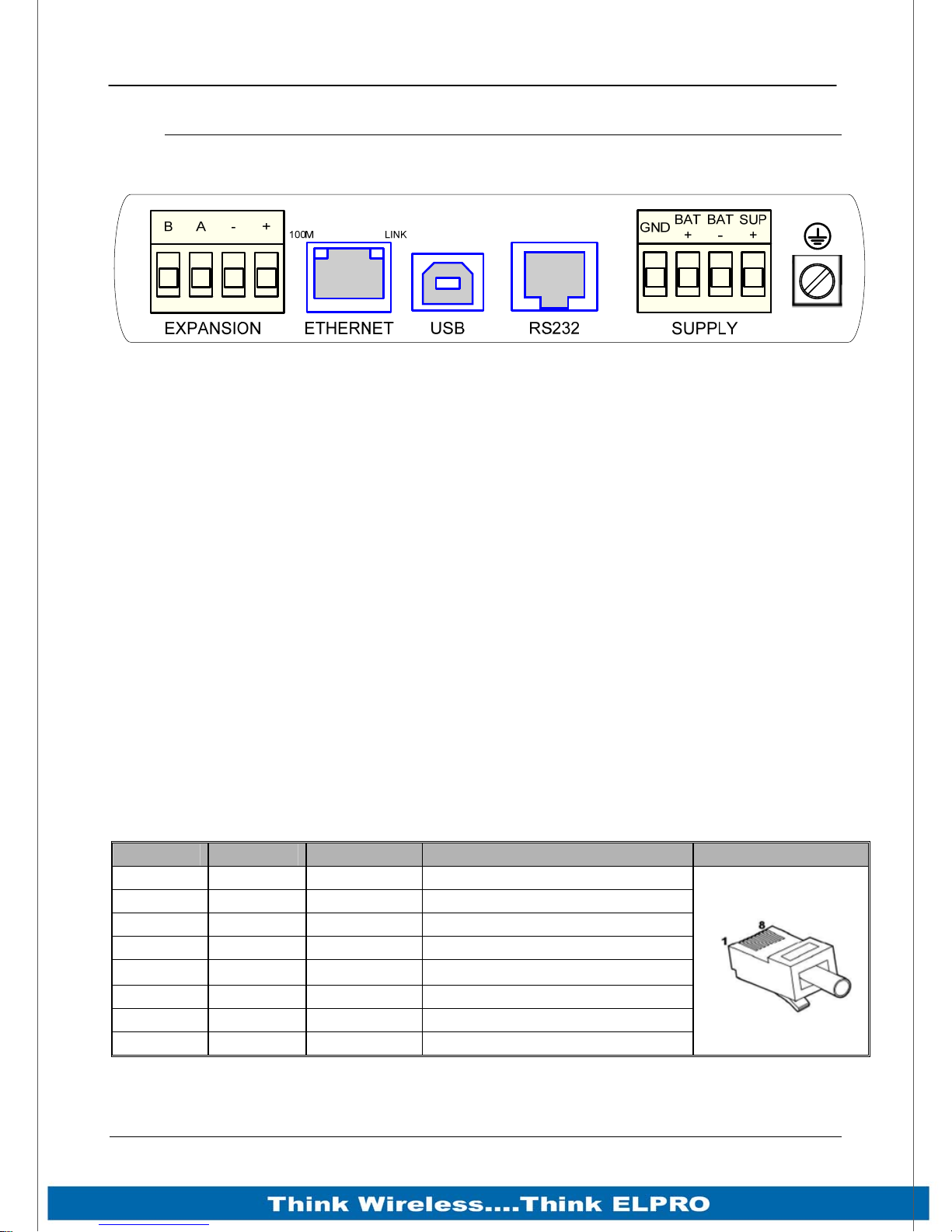
Page 24 915U-2 Wireless I/O
2.5 Connections
2.5.1 Bottom panel connections
Figure 9 – Bottom Panel Connections
Ethernet port
The 915U-2 modules provides a standard RJ-45 Ethernet port compliant to IEEE 802.3
10/100 BaseT. This port provides full access to the module, including configuration,
diagnostics, log file download and firmware upload, of both the local and remote units.
Additionally the Ethernet port can provide network connectivity for locally connected
third-party devices with Ethernet functionality.
USB Device Port for configuration
The 915U-2 module also provides a USB-device (USB-B) connector. This connector
provides configuration of the device and remote configuration access to other devices in
the radio network.
RS-232 port
The 915U-2 module provides an RS-232 serial port, which support operations at data
rates up to 230,400 baud. This port supports MODBUS protocol.
The RS-232 port is provided by an RJ-45 connector wired as a DCE according to EIA562 Electrical Standard.
RJ-45 Signal Required Signal name Connector
1 RI Ring Indicator
2 DCD Data Carrier Detect
3 DTR Y Data Terminal Ready
4 GND Y Signal Common
5 RXD Y Receive Data (from Modem)
6 TXD Y Transmit Data (to Modem)
7 CTS Clear to Send
8 RTS Request to Send
Page 24 915U-2 Wireless I/O
Page 26
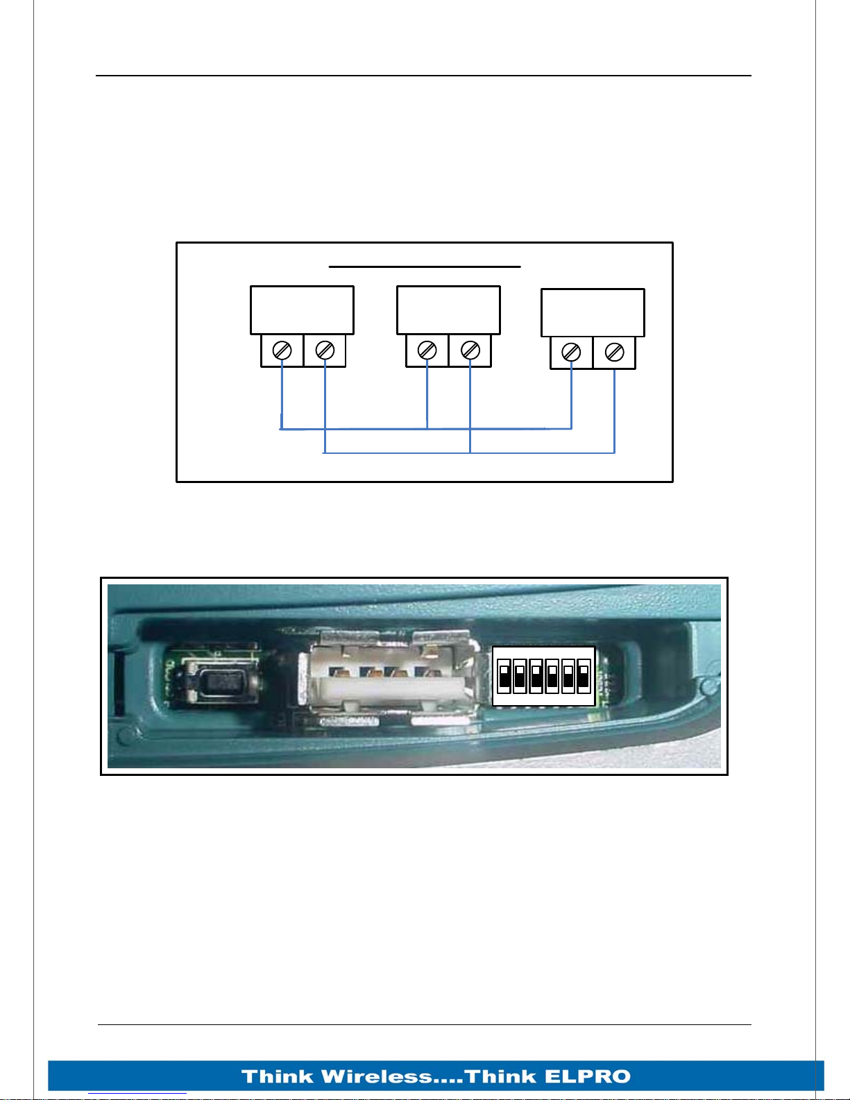
915U-2 Wireless I/O Page 25
RS-485 port with Modbus Support.
The 915U-2 module provides an RS-485 serial port, which supports operations at data
rates up to 230,400 baud. Default baud rate is 9600 baud, No Parity, 8 data bits and 1
stop bit which match the 115S serial expansion modules defaults. This port Supports
MODBUS protocol.
The RS-485 port is provided by two screw terminals. On-board termination of the RS485 circuit is built-in.
RS485 Connections
915U-2
Serial
Device
+
Figure 10 – RS485 Connections
2.5.2 Side Access Configuration Panel
Factory
Boot
DipswitchesUSB Host
1ON23456
Serial
Device
+
On the side of the module is a small access cover that hides a “Factory Boot” switch,
USB Host port and a small bank of dipswitches that are used for Analog input
voltage/current selection, External Boot and Default configuration settings.
“Factory Boot” switch
The “Factory Boot” switch is used for factory setup and diagnostics. This switch should
not normally be used, except if advised by ELPRO support.
Page 25 915U-2 Wireless I/O
Figure 11 – Side Access Panel
Page 27
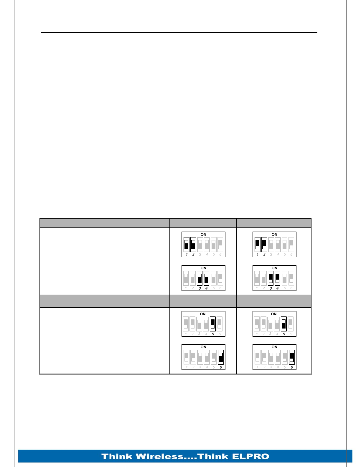
Page 26 915U-2 Wireless I/O
USB Host port
This port is a USB Host (Master port), which can interface with USB storage devices for
data logging (Future) and for upgrading the module Firmware – See section 4.4
“System Tools” for details on how this is done.
Dipswitches
The Dipswitches are used to select a number of functions within the module; the table
below indicates the different switch positions.
Dipswitches 1 to 2 – Selection for measuring Current or Voltage on Analog Input
3. Set DIP switches ON to measure Current (0-20mA) and OFF for Voltage (05VDC).
Dipswitches 3 to 4 – Selection for measuring Current or Voltage on Analog Input
4. Set DIP switches ON to measure Current (0-20mA) and OFF for Voltage (05VDC).
Dipswitch 5 – DIP Switch not used
Dipswitch 6 – When set to ON (Enabled), the module will boot up with a known
factory default including a default IP address for Ethernet connection. (Refer to
4.1 “Default ”)
Switch Function Current Voltage
DIP 1 & 2 Analog Input #3
DIP 3 & 4 Analog Input #4
Switch Function Enabled Disabled
DIP 5 Not used
DIP 6
Default
Configuration
Page 26 915U-2 Wireless I/O
Page 28
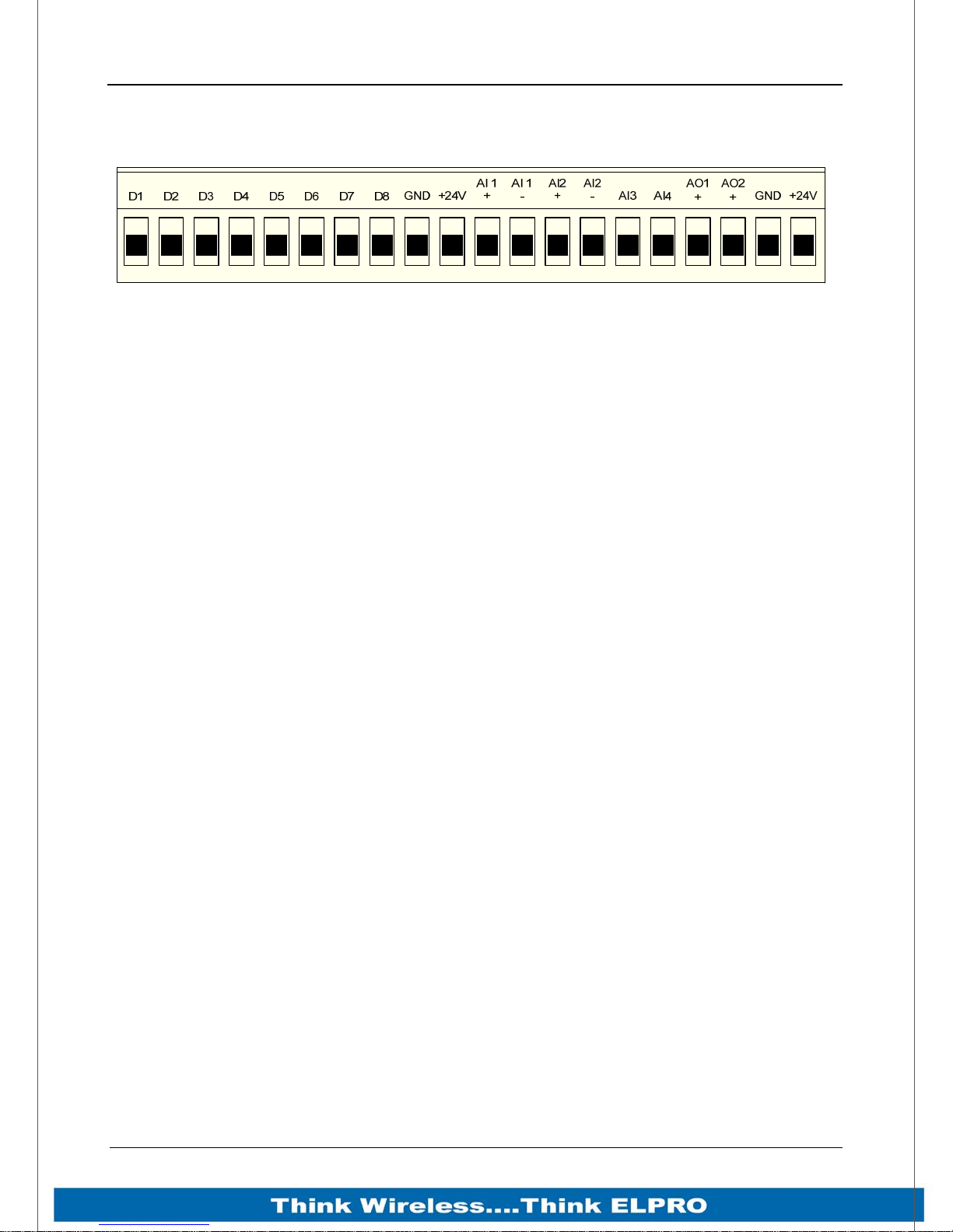
915U-2 Wireless I/O Page 27
Front panel connections
Figure 12 – Front Panel Connections
The 915U-2 front panel provides connections for the following
Eight Digital Input /Output (DIO1-8).
Two 12 bit, 0.1% accuracy differential analog inputs.
Two single ended 12 bit, 0.1% accuracy analog inputs.
Two 15 bit, 0.1% accuracy current sourcing analog outputs.
Connection terminals for Common and +24V Analog Loop Supply (ALS
maximum current limit is 150mA).
Page 27 915U-2 Wireless I/O
Page 29
Page 28 915U-2 Wireless I/O
2.5.3 Digital Inputs
Each digital I/O channel on the 915U-2 can act as either an input or an output. The
input/output direction is automatically determined by the connections and configuration
of the I/O.
If you have an I/O channel wired as an input but operate the channel as an output. No
electrical damage will occur however, the I/O system will not operate correctly.
If operating the channel as an output and performing a “read inputs” on this location it
will indicate the status of the output.
Marked DIO1-8 the Digital inputs share the same terminals as the Digital outputs on the
915U-2 module.
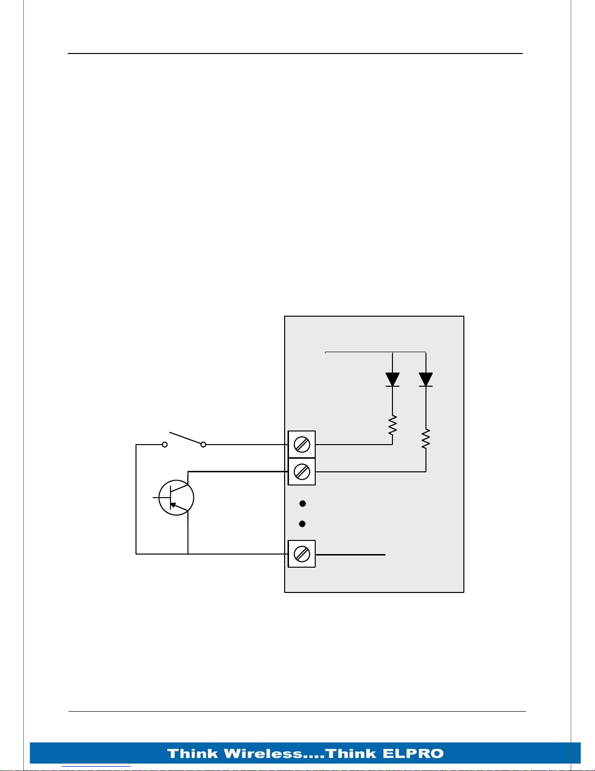
A digital input is activated by connecting the input terminal to EARTH or Common, either
by voltage-free contact, TTL Level, or transistor switch.
Each digital input has an orange indication LED that will turn on when the input has
been connected to a GND or common.
Discrete Input / Output Used as input
Voltage Free Cont act
Transistor
Switch Device
915U-2
V+
DIO1
DIO2
Common
Figure 13 – Digital Input Wiring
V-
Page 28 915U-2 Wireless I/O
Page 30
915U-2 Wireless I/O Page 29
2.5.4 Pulsed Inputs
The 915U-2 supports 8 x digital signals, of which inputs 1-4 can be used as pulsed
inputs.
The maximum pulse frequency is 50 KHz for Input 1 & 2 and 1 KHz for Input 3 & 4.
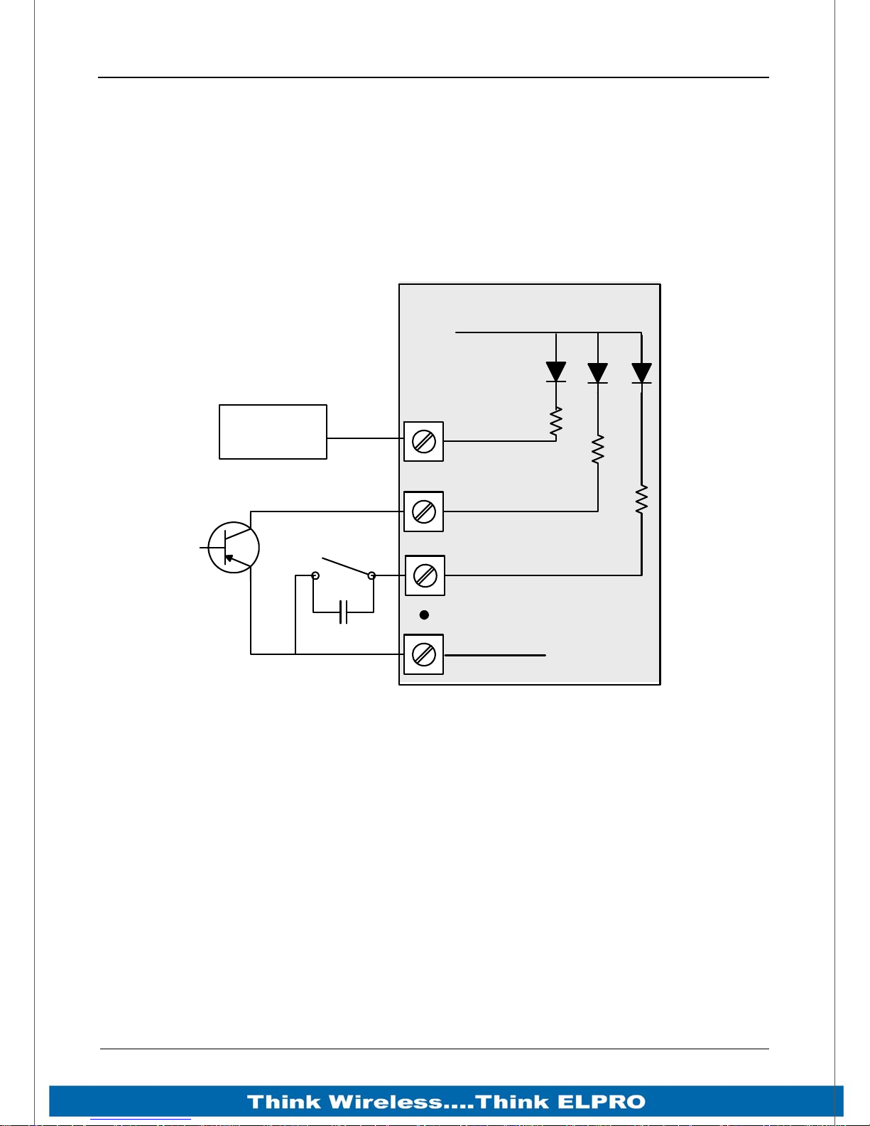
Digital/Pulsed inputs are suitable for TTL signal Level, NPN-transistor switch devices or
voltage-free contacts (relay/switch with debounce capacitor).
Pulsed Inputs
915U-2
V+
TTL CMOS
Output
DIO1
Transistor
Switch Device
DIO2
DIO3
Common
V-
Voltage Free
Contact
Figure 14 – Pulsed Input Wiring
Frequencies greater than 1 KHz need to use a TTL logic drive or an external pull-up
resistor. Pulsed inputs are converted to two different values internally. First is the Pulse
Count, which is an indication of how many times the input has changed state over a
configured time period. Secondly there is a Pulse Rate which is an analog input derived
from the pulse frequency. E.g. 0 Hz = 4mA and 1 KHz = 20mA.
Page 29 915U-2 Wireless I/O
Page 31
Page 30 915U-2 Wireless I/O
2.5.5 Digital Outputs (Pulsed Outputs)
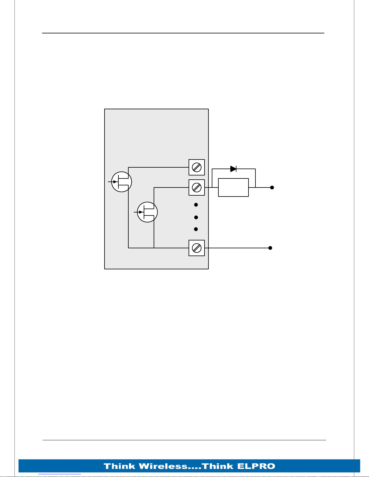
Digital outputs are open-collector transistors and are able to switch loads up to 30VDC,
200mA.
The 8 digital outputs share the same terminals as the digital input. These terminals are
marked DIO1-8.
Discrete Input / Output Used as output
915U-2
DIO1
DIO2
DC Load
+
Max 30VDC
0.2A
_
V-
When active, the digital outputs provide a transistor switch to EARTH (Common).
To connect a digital output, refer to “Figure 15” above. A bypass diode (IN4004) is
recommended to protect against switching surges for inductive loads such as relay
coils.
The digital channels DIO1-4 on the 915U-2 module can be used as pulse outputs with a
maximum output frequency of 1 KHz.
Common
Figure 15 – Digital Output Wiring
Digital Output Fail Safe Status
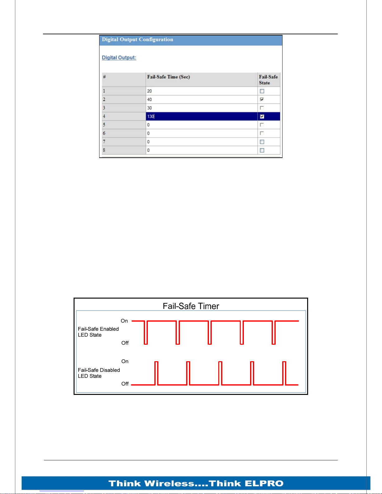
As well as indicating the Digital Output status (on / off), the LEDs can also indicate a
communications failure by flashing the Output LED. This feature can be utilised by
configuring a Fail Safe time and status on the “I/O Configuration” web page as shown
below.
Page 30 915U-2 Wireless I/O
Page 32
915U-2 Wireless I/O Page 31
Figure 16 – Digital Output Failsafe Times
The Fail Safe Time is the time the output counts down before activating a Fail Safe
state.
Normally this would be configured for a little more than twice the update time of the
mapping that is sending data to it.
This is because the Fail Safe Timer is restarted whenever it receives an update. If we
send successive update messages and fail to receive both the timer counts down to
zero and then activates the Failsafe state.
If the Failsafe state is enabled (ON) this will indicate with the LED flashing briefly OFF
and the digital output will turn on.
If the Failsafe state is disabled (OFF) this will indicate with the LED flashing briefly ON
and the digital output will turn off.
Figure 17 - Fail-Safe State
Page 31 915U-2 Wireless I/O
Page 33
Page 32 915U-2 Wireless I/O
2.5.6 Analog Inputs
The 915U-2 can provide two floating differential analog inputs and two grounded singleended analog inputs.
Analog Input 1 & 2 can automatically measure Current (0-20 mA) or Voltage (0-25V)
depending on what is connected to the input.
Analog input 3 & 4 must be configured to measure Current (0-20mA) or Voltage (0-5V)
via the DIP switches under the Side Access Configuration Panel (See Section 2.5.2 ).
An internal 24V Analog Loop Supply (ALS) provides power for any current loops with a
maximum current limit of 150mA.
The LEDs have an analog diagnostic function and will indicate the status of the input.
If the current is less than 3.5 mA the LED will be off and if greater than 20.5mA the LED
will be on.
The LED will flicker with the duty cycle relative to the analog reading in this range. (Note
by default there is a 5 second delay on the input because of the Filter)
Also, LEDs beside AI1+, AI2+ flash according to current on these inputs. LEDs beside
AI1- and AI2- flash according to the voltage on the Analog inputs.
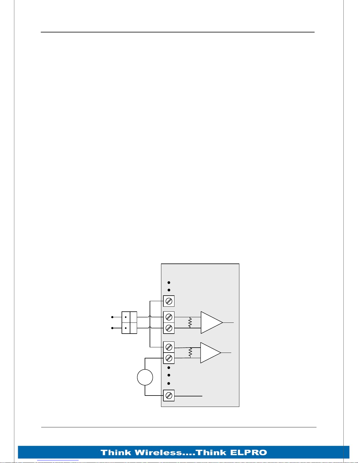
Differential Current Inputs (AIN 1 & 2 only)
Differential mode current inputs should be used when measuring a current loop, which
cannot be connected to earth or ground. This allows the input to be connected
anywhere in the current loop. Common mode voltage can be up to 27VDC.
The diagram below indicates how to connect Loop powered or externally powered
devices to the 915U-2 Differential Analog Inputs.
915U-2
Externally powered
sensor
+
ALS +24V
AIN1+
_
AIN1-
AIN2+
AIN2-
GND
V-
Loop
powered
sensor
+
mA
-
Page 32 915U-2 Wireless I/O
Figure 18 – Differential Current Inputs
Page 34
915U-2 Wireless I/O Page 33
Single Ended Current Inputs (AIN 3 & 4 only)
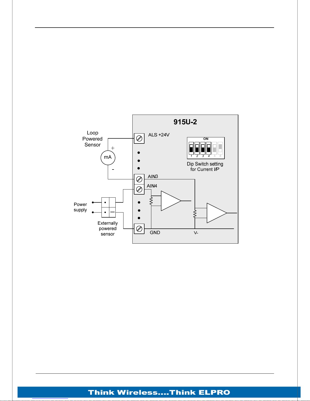
Single-ended current input mode is useful if the sensor loop is grounded to the 915U-2
module. Devices can be powered from the 24V Analog Loop Supply (ALS) generated
internally from the module.
The Dip Switches are used to determine if the inputs will be current or voltage.
Dip Switches 1 & 2 are used for or Analog 3 and Dip Switches 3 & 4 are used for Analog
4
For Current set both Dip Switches to the “On” position, for Voltage set both to “Off”
+
Figure 19– Single Ended Current Inputs
Page 33 915U-2 Wireless I/O
Page 35
Page 34 915U-2 Wireless I/O
Single Ended Voltage Inputs
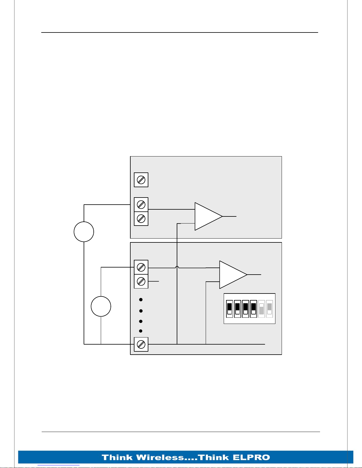
All analog inputs can be setup to read voltage.
If using Analog input 1 & 2 connect the voltage source across the positive terminal of
the input and Common.
If using Analog input 3 & 4 then connect across the input terminal and Common.
Note:
Default scaling gives 0-25V for 4-20mA output on Analog 1 and 2.
Default scaling for analog 3 and 4 gives 0-5V for 4-20mA output.
For Voltage input on analog 3 and 4 set both Dip Switches to the “Off” position,
915U-2
ALS +24V
Differential Voltage
AIN1+
Inputs (AI1&2)
+
0-25V
AIN1-
Sensor
V
-
Single Ended Voltage
Input (AI3&4)
AIN3
0-5VDC
Sensor
AIN4
+
V
-
GND
Figure 20 – Voltage Inputs
V-
1ON23456
Dip Switch setting
for Voltage I/P
Page 34 915U-2 Wireless I/O
Page 36
915U-2 Wireless I/O Page 35
2.5.7 Analog Outputs
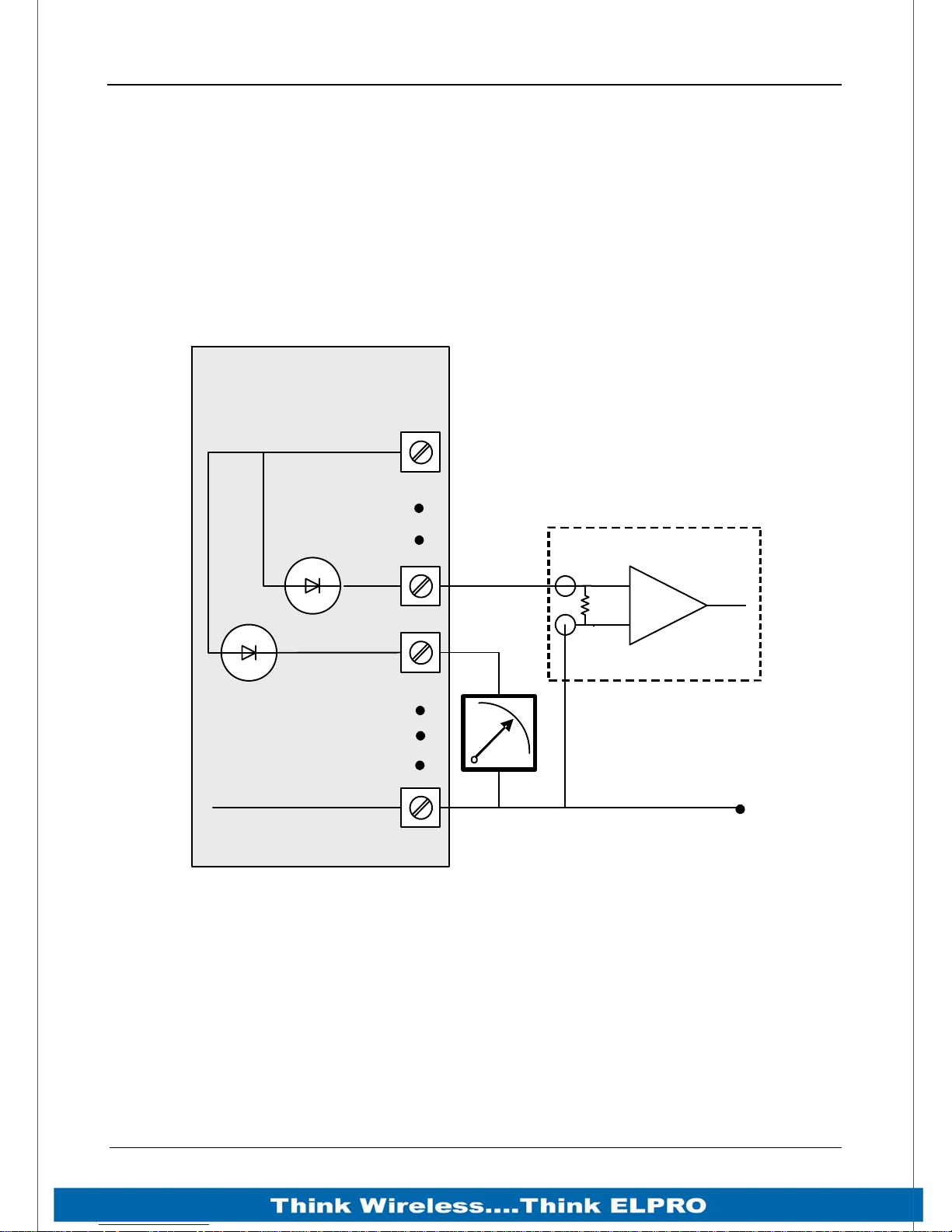
The 915U-2 module provides two 0 - 24 mA DC analog outputs for connecting to
instrument indicators for the display of remote analog measurements.
The 915U-2 Analog outputs are a sourcing output and should be connected from the
analog output terminal through the device or indicator to Common. See diagram for
connections.
The LEDs function as a primitive level indicator depending on current - Dim for 4mA and
Bright for 20mA
915U-2
ALS +24V
V-
AOT1
AOT2
GND
Figure 21 – Analog Outputs
AI
COM
PLC
+
-
Page 35 915U-2 Wireless I/O
Page 37
Page 36 915U-2 Wireless I/O
Chapter 3 - Operation
3.1 Overview
The 915U-2 range of I/O modules has been designed to provide standard “off-the-shelf”
telemetry functions, at an economic price. Telemetry is the transmission of data or
signals over a long distance via radio or twisted-pair wire cable.
3.2 Indications
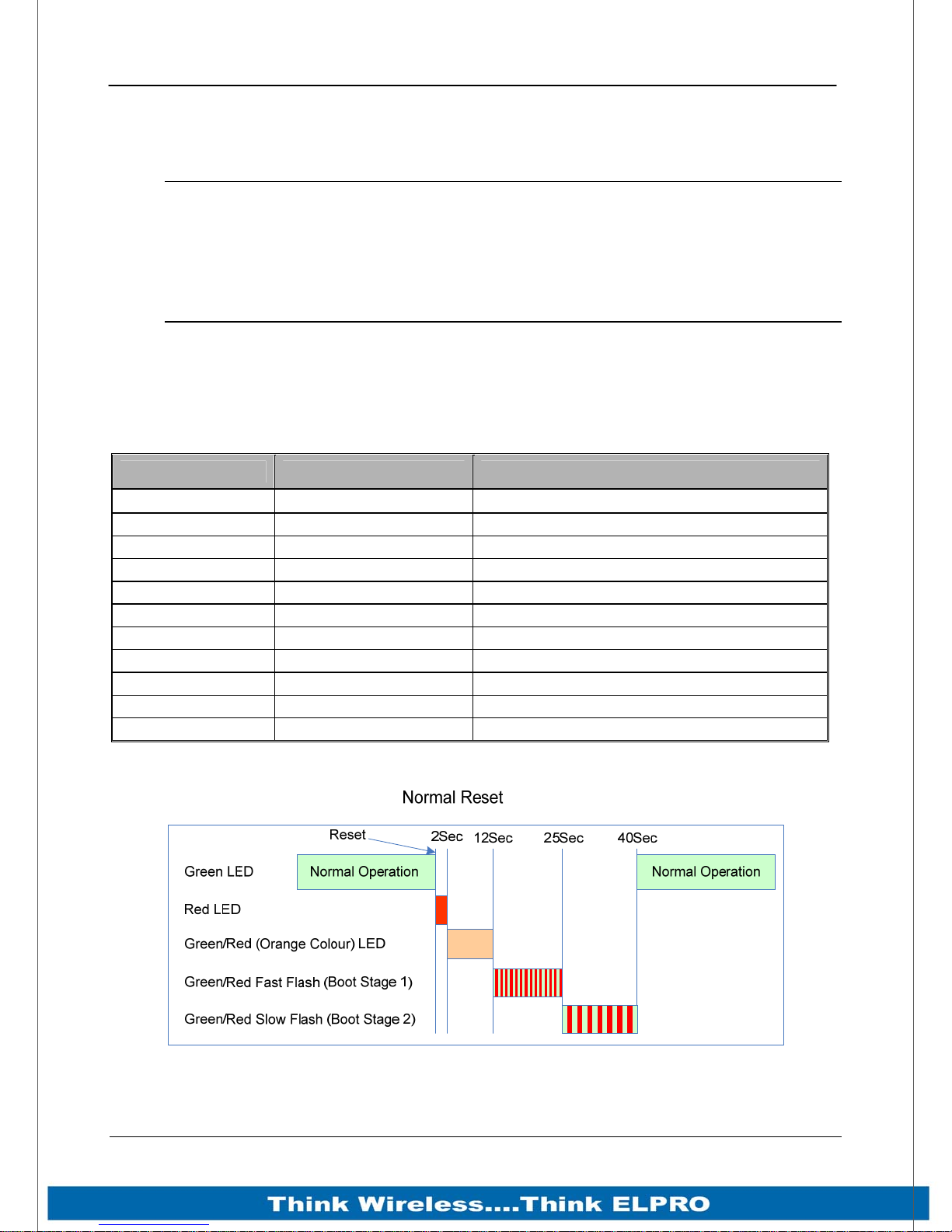
When power is initially connected to the module it will perform some internal setup and
diagnostics checks to determine if the module is operating correctly. These checks will
take approximately 40 seconds. The table below shows the correct LED sequences.
3.2.1 Front Panel Indications
LED Indicator Condition Meaning
PWR GREEN System OK
PWR Fast Flash System Boot – Stage 1
PWR SLOW Flash System Boot – Stage 2
PWR RED System Boot – Initial / System Failure
RF GREEN Receiving Radio data
RF RED Transmitting Radio data
232 GREEN Receiving RS232 data
232 RED Transmitting RS232 data
232 ORANGE Transmitting and Receiving RS232 data
485 GREEN Receiving RS485 data
485 RED Transmitting RS485 data
3.2.2 Boot Sequence “PWR” LED Indications
Figure 22 - Boot Sequence
Page 36 915U-2 Wireless I/O
Page 38
915U-2 Wireless I/O Page 37
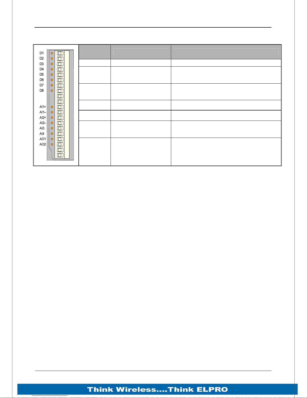
3.2.3 Input / Output Indications
LED
Indicator
D 1- 8 ORANGE Digital input ON
D 1- 8
D 1- 8
AI 1 & 2 + ORANGE Analog input current indication
AI 1 & 2 – ORANGE Analog input voltage indication
AI 3 & 4 ORANGE
AO1 & 2 ORANGE Analog output current indication
Condition Meaning
FLASHING ORANGE
- Mostly On
FLASHING ORANGE
- Mostly Off
Update Failure - Failsafe state On
Update Failure - Failsafe state Off
Analog input current or voltage
indication
Digital Inputs
LED’s display the status of each of the eight DIO’s when used as inputs. (If the LED is lit
then the input is on).
Digital Outputs
When the DIO’s are used as outputs the LEDs will display the status of each of the
digital output (If the LED is lit then the output is on). The LED’s also indicate if the output
has not been updated by flashing. Mostly ON will indicate the Failsafe state is ON and
mostly OFF will indicate the Failsafe state is OFF.
Analog Inputs
Two LEDs exist for each Differential analog input. The first LED (+) is used to indicate
the analogue input is reading a Current (mA), the second LED (-) indicates the input is
reading Voltage.
Each of the analog input LEDs will flash with increasing speed and intenseness
depending on the level of the input (4mA = slow/dim and 20mA= fast/bright)
For each of the single ended analog channels, the LED indicates when the input is
reading Current or Voltage by flashing the LED with the level of the input (4mA =
slow/dim and 20mA= fast/bright).
Analog Outputs
Each Analog output has an LED in series which will indicate the output current by
increasing/decreasing the intensity of the LED. (4mA = dim and 20mA= bright)
Page 37 915U-2 Wireless I/O
Page 39

Page 38 915U-2 Wireless I/O
3.2.4 Ethernet Indications
On the end plate, the ethernet socket incorporates two LED’s These LEDs indicating the
Ethernet status
100M – GREEN LED indicates presence of a 100 Mbit /s
Ethernet connection, with a 10 Mbit /s connection the LED will
be off.
LINK – ORANGE indicates an Ethernet connection and LED
briefly flashes “off” with activity.
Page 38 915U-2 Wireless I/O
Page 40

915U-2 Wireless I/O Page 39
3.3 System Design
3.3.1 Radio Channel Capacity
Messages sent on a cable link are much faster than on a radio channel, and the
capacity of the radio channel must be considered when designing a system. This
becomes more important as the I/O size of a system increases.
The modules are designed to provide “real-time” operation or Change of State (COS).
When an input signal changes, the change message is sent to the output. The system
does not require continuous messages as in a polling system. Update messages are
intended to check the integrity of the system, not to provide fast operation. Update times
should be selected based on this principle. The default update time in the mappings is
10 minutes - we recommend that you leave these times as is unless particular inputs
are very important and deserve a smaller update time.
It is important that radio paths be reliable. For large systems, we recommend a
maximum radio channel density of 300 messages per minute, including change
messages and update messages. We suggest that you do not design the system with
more than 300 messages per minute as this does not take into account any network
communication overheads. Note that this rate assumes that all radio paths are reliable
and the network topology (mesh) is stable - poor radio paths will require retransmissions
and will reduce the channel density. If there are other users on the radio channel, then
this peak figure will also decrease.
Having remotes radios dropping in and out of communications can also increase overall
network traffic because the network would need to relearn the communication paths
each time the module comes back on line.
Dual Band Operation
The 915U-2 radio band is split into two sub-bands, 902-914 MHz (Low) and 915–928
MHz (High). In America and Canada, the 915U-2 uses both sub-bands - but in other
countries, e.g. Australia only the high band is available. In America and Canada, it is
possible to restrict the frequency hopping of the 905U to only the high or low band. If
there are many 905U systems in the same area, this technique will help to separate
systems to avoid radio interference. Note that this technique is only possible in
countries that utilize the full 902-928MHz bandwidth, i.e. America / Canada, etc.
The radio sub-band can be changed by selecting the “Hop Set” on the Radio page.
3.3.2 Radio Path Reliability
Radio paths over short distances can operate reliably with a large amount of obstruction
in the path. As the path distance increases, the amount of obstruction that can be
tolerated decreases. At the maximum reliable distance, “line-of-sight” is required for
reliable operation. The curvature of the earth becomes more of an obstacle if the path is
greater than several kilometres (or miles), and therefore needs to be allowed for. For
example, the earth curvature over 5 miles (8km) is approx 10 feet (3m), requiring
antennas to be elevated at least 13 feet (4m) to achieve “line-of-sight” even if the path is
flat.
Page 39 915U-2 Wireless I/O
Page 41

Page 40 915U-2 Wireless I/O
A radio path may act reliably in good weather, but poorly in bad weather - this is called a
“marginal” radio path. If the radio path is more than 20% of the maximum reliable
distance (see Specification section for these distances), we recommend that you test
the radio path before installation. Each 915U-2 module has a radio path-testing feature refer to Section 5.2 ”Connectivity” of this manual.
There are several ways of improving a marginal path:-
Relocate the antenna to a better position. If there is an obvious obstruction
causing the problem, then locating the antenna to the side or higher will improve
the path. If the radio path has a large distance, then increasing the height of the
antenna will improve the path.
Use an antenna with a higher gain. Before you do this, make sure that the
radiated power from the new antenna is still within the regulations of your
country. If you have a long length of coaxial cable, you can use a higher gain
antenna to cancel the losses in the coaxial cable.
If it is not practical to improve a marginal path, then the last method is to use
another module as a repeater. A repeater does not have to be between the two
modules (although often it is). If possible, use an existing module in the system,
which has good radio path to both modules. The repeater module can be to the
side of the two modules, or even behind one of the modules, if the repeater
module is installed at a high location (for example, a tower, or mast). Repeater
modules can have their own I/O and act as a “normal” 915U-2 module in the
system.
3.3.3 Design for Failures
All well designed systems consider system failure. I/O systems operating on a wire link
will fail eventually, and a radio system is the same. Failures could be short-term
(interference on the radio channel or power supply failure) or long-term (equipment
failure).
The modules provide the following features for system failure:-
Outputs can reset if they do not receive a message within a configured time. If an
output should receive an update or change message every 10 minutes, and it
has not received a message within this time, then some form of failure is likely. If
the output is controlling some machinery, then it is good design to switch off this
equipment until communications has been re-established.
The modules provide a “drop outputs on comms fail” time. This is a configurable
time value for each output. If a message has not been received for this output
within this time, then the output will reset (off, in-active, “0”). We suggest that this
reset time be a little more than twice the update time of the input. It is possible to
miss one update message because of short-term radio interference, however if
two successive update messages are missed, then long term failure is likely and
the output should be reset. For example, if the input update time is 3 minutes, set
the output reset time to 7 minutes.
Page 40 915U-2 Wireless I/O
Page 42

915U-2 Wireless I/O Page 41
A module can provide an output, which activates on communication failure to
another module. This can be used to provide an external alarm that there is a
system fault.
3.3.4 Indicating a Communications Problem
There are two ways to indication communications problems.
Fail-to-transmit alarm
The first method is to setup a communications indication on a register of your choice
when configuring a mapping. This can be done using an existing mapping (do not need
to setup a special comms mapping).
When entering a Block Write or Gather/Scatter Mapping you need to enter into the
“FailReg” field a register location that you wish to indicate a communications fail (As
mentioned previously this register can be a local DIO (Reg 1-8) or an internal register.
When ever the module tries to send this mapping and fails to get a response (Ack) it will
turn on the output.
The Comms Fail indication will clear on the next successful transmission of the
mapping.
This method will work with any number repeaters in the link; however it will only indicate
a failure to transmit if the mapping has the "ACK" field checked.
It will not give a Fail indication if the mappings are configured as Transmit only (do not
have the “Ack” ticked).
Fail-to-receive alarm
The second method is to set up a “Comms Link” indication on the receiving end using
normal Write Mappings on the transmitting end and the “Fail Safe Time” function on the
receiving end. Setup a comms mapping from an unused digital input (can be an internal
signal, i.e. Supply fail) and have it mapped to the output that will indicate the
communication status. The input will be updated at a given time interval (default will be
5 seconds) but select a time that will give a good indication of failure but not update so
much that it generates too many comms check messages, e.g. 30 seconds.
On the receiving end, configure a “Fail Safe Time” on the output that it being mapped to
of twice the update time e.g. 1 minute. Next, configure the Fail Safe State to be on
“ticked” which will turn on the output when it fails to be updated. Alternatively, you could
invert the mapping so the output was always on and then trigger the “Fail Safe State” to
go off when not updated.
This method will work with any number repeaters in the link.
You should use separate outputs to indicate “comms OK” of different remote modules.
3.3.5 Testing and Commissioning
We recommend that that the system is fully tested on the bench before installation. It is
much easier to find configuration problems on the bench when the modules are next to
each other as apposed to being miles apart.
Page 41 915U-2 Wireless I/O
Page 43

Page 42 915U-2 Wireless I/O
When the system is configured and you are happy that it all works, backup the
configurations of all the modules.
After installation, record the radio signal strength and background noise level for each
radio link. If there are future communications problems, you can compare the present
measurements to the as-commissioned values. This is an effective way of finding
problems with antennas, cables, and changes in the radio path (for example, the
erection of new buildings).
3.4 WIBMesh
The ELPRO WIBMesh protocol is based on the “Ad hoc On-demand Distance Vector”
(AODV) routing algorithm which is a routing protocol designed for ad hoc networks.
AODV is capable of unicast (single addressed message) routing and is an “on-demand”
protocol, meaning that it builds and maintains these routes only as long as they are
needed by the source devices. In other words the network is silent until a connection is
needed. The Protocol creates a table, which shows the connection routes to other
device in the system and uses sequence numbers to ensure the routes are kept as
current as possible.
When a module in a network needs to make a connection to another module it
broadcasts a request for connection. Other modules forward this message, and record
the module address that they heard it from, creating a table of temporary routes back to
the starting module. If a module receives a request and it already has an existing route
to the request destination, it will send a message backwards through the temporary
route to the requesting module.
Each request for a route has a sequence number. Modules use this sequence number
so that they do not repeat route requests that they have already passed on. Another
such feature is that the route requests have a "time to live" number that limits how many
times they can be retransmitted. Another such feature is that if a route request fails,
another route request may not be sent until twice as much time has passed as the
timeout of the previous route request.
The original starting module then begins using the route that has the least number of
hops. Unused entries in the routing tables are recycled after a time.
When a link fails, a routing error is passed back to a transmitting node, and the process
repeats.
Page 42 915U-2 Wireless I/O
Page 44
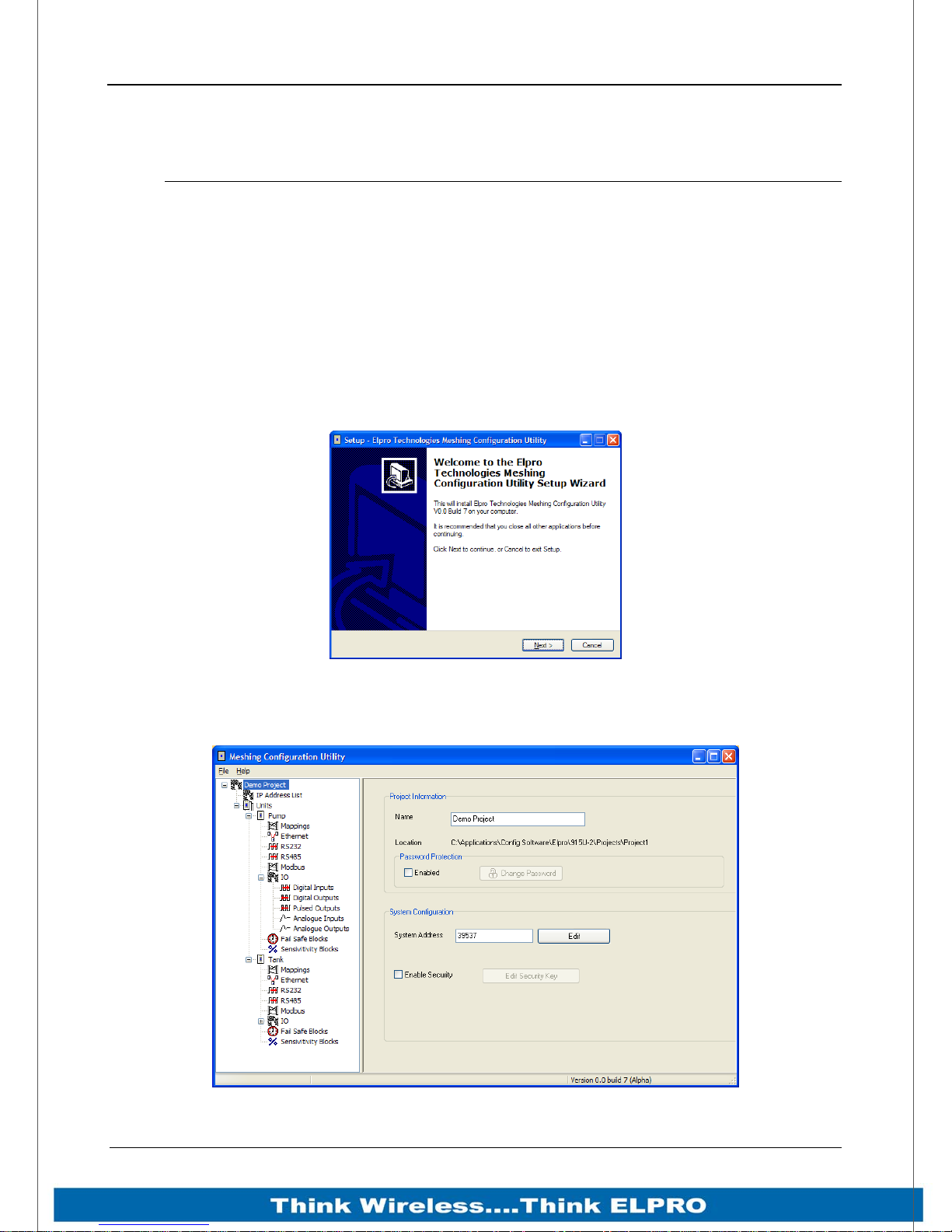
915U-2 Wireless I/O Page 43
Chapter 4 - Configuration
4.1 Module Configuration
Module configuration can be done using the ELPRO MConfig utility or via inbuilt web
pages. We recommend the software be used as the primary config as is easier to use
and simplifies the overall configuration. It is also project based which means you can
group a number of modules in one configuration file.
For instructions on web page based configurations see Appendix E: “Web Page
Configuration”
The Utility is available from the download section on the ELPRO Technologies web site
- www.elprotech.com.
After downloading, run the file to install the software on to your computer.
Figure 23 - Installation
The software is compatible with all current Windows versions and uses a simple point
and click interface. Configuration of the module can be via USB or Ethernet connection.
Figure 24 – Configuration Software
Page 43 915U-2 Wireless I/O
Page 45
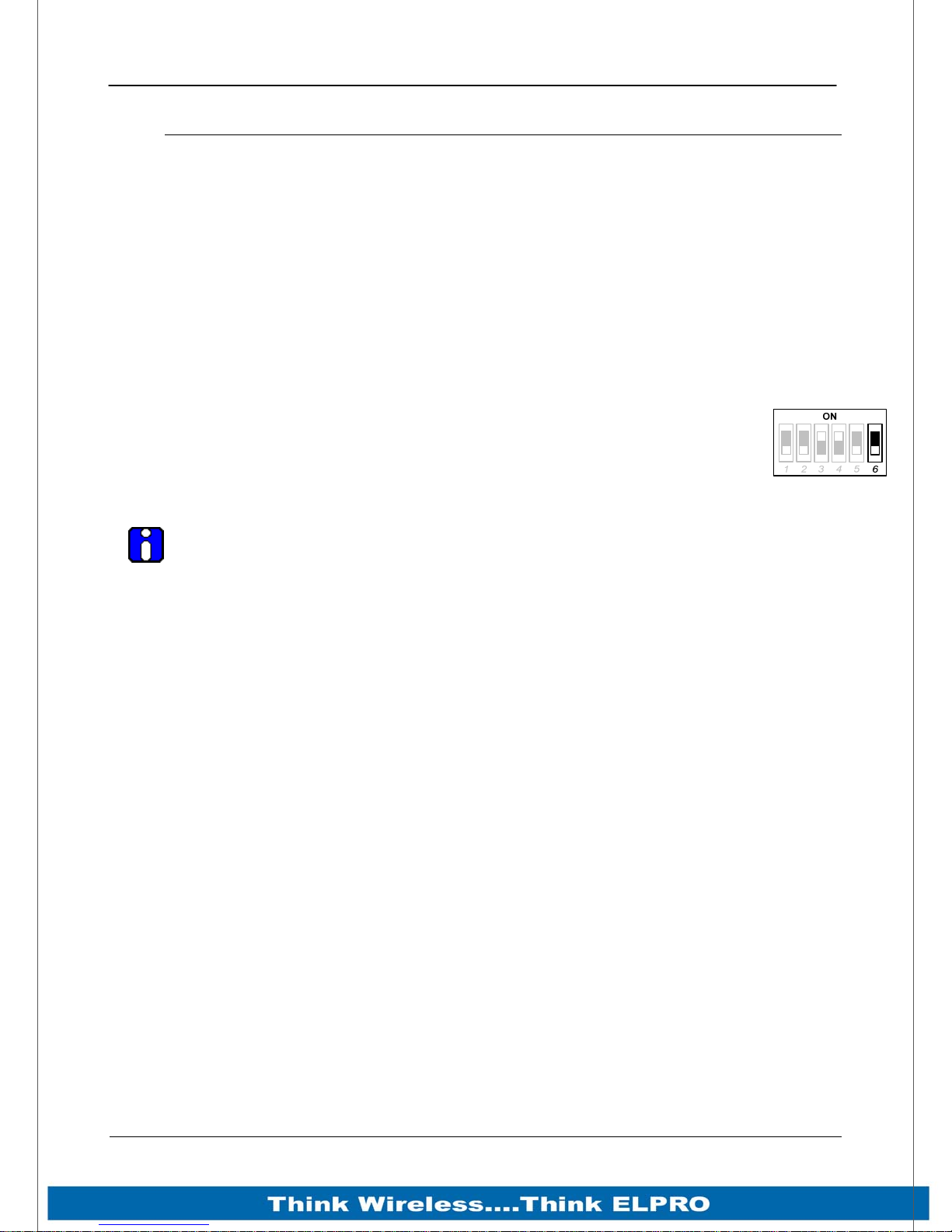
Page 44 915U-2 Wireless I/O
4.2 First time Configuration
The 915U-2 has a built-in web server, containing web pages for analyzing and minor
modification to the module’s configuration. The configuration can be accessed using any
web browser however we recommend using Microsoft® Internet Explorer 8.
4.2.1 Default IP Address
The default factory IP Address of the 915U-2 is 192.168.0.1XX, where XX is the last two
digits of the serial number (the default “Setup IP address” is shown on the printed label
on the side of the module)
Netmask 255.255.255.0
Username is “user” and the default password is “user”
The 915U-2 will temporarily load some factory-default settings if powered up
with the #6 dipswitch under the side configuration panel switched on. When in
SETUP mode, wireless operation is disabled. The previous configuration
remains stored in non-volatile memory and will only change if a configuration
parameter is modified and the change saved.
Do not forget to set the switch back to the OFF position and re-cycle the power
at the conclusion of the configuration for normal operation otherwise, it will
continue to boot into the default IP address.
4.2.2 Accessing Configuration
The Default IP address is in the range 192.168.0.XXX and so will require a PC on this
network or be able to change the network settings to access the module configuration.
This is the procedure for changing A PC network settings.
You will need a “straight-through” Ethernet cable between the PC Ethernet port and the
915U-2. The factory default Ethernet address for the 915U-2 is 192.168.0.1XX where
XX are the last two digits of the serial number (check the label on the back of the
module).
Connect the Ethernet cable between unit and the PC configuring the module.
Open the side configuration panel and set the #6 Dipswitch to ON.
With this switch on the 915U-2 will always start with the Ethernet IP address
192.168.0.1XX, subnet mask 255.255.255.0, Gateway IP 192.168.0.1 and the radio IP
address 192.168.2.1. Do not forget to set the switch back to the OFF position and
restart the module at the conclusion of configuration.
Page 44 915U-2 Wireless I/O
Page 46
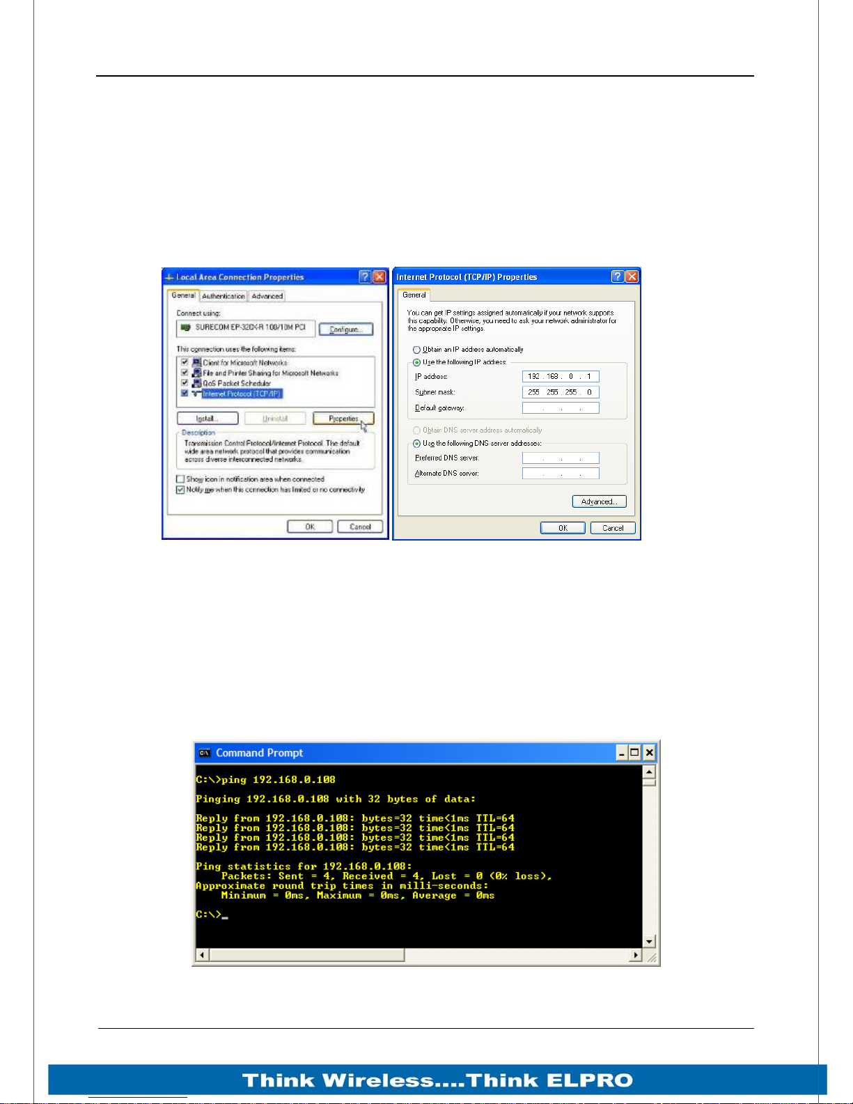
915U-2 Wireless I/O Page 45
4.2.3 Power up the 915U-2 module.
Open “Network Settings” on your PC under Control Panel. The following description is
for Windows XP - earlier Windows operating systems have similar settings.
Open “Properties” of Local Area Connection.
Select Internet Protocol (TCP/IP) and click on Properties.
On the General tab, enter IP address 192.168.0.1, Subnet mask 255.255.255.0 and
press “OK”
Figure 25 – Network Settings
The simplest way to check ethernet communications is to use the “Ping” command
From the Windows Start menu, select “Run” then type “command”
A Command Prompt DOS window will open and from there you can use the Ping
command to check if you are able to connect to the module.
Type ping 192.168.0.1XX (where XX is the last two digits of the serial number)
You should then see a reply like below.
Page 45 915U-2 Wireless I/O
Figure 26 - Ping
Page 47
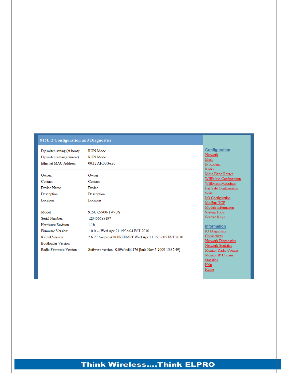
Page 46 915U-2 Wireless I/O
You can then open Internet Explorer and ensure you can connect to the IP address
selected. If the PC uses a proxy server, ensure that Internet Explorer will bypass the
Proxy Server for local addresses.
This option may be modified by opening Tools -> Internet Options -> Connections Tab > LAN Settings->Proxy Server -> bypass proxy for local addresses.
Enter the default IP address for the 915U-2 https://192.168.0.1XX where XX is the last
two digits of the serial number.
Enter the username “user” and default password “user”.
When Configuration is complete switch the 915U-2 Factory Default dip-switch to RUN
and cycle power to resume normal configured operation.
You should now see the Module Welcome Screen (below)
Page 46 915U-2 Wireless I/O
Figure 27 – Main Welcome Screen
Page 48
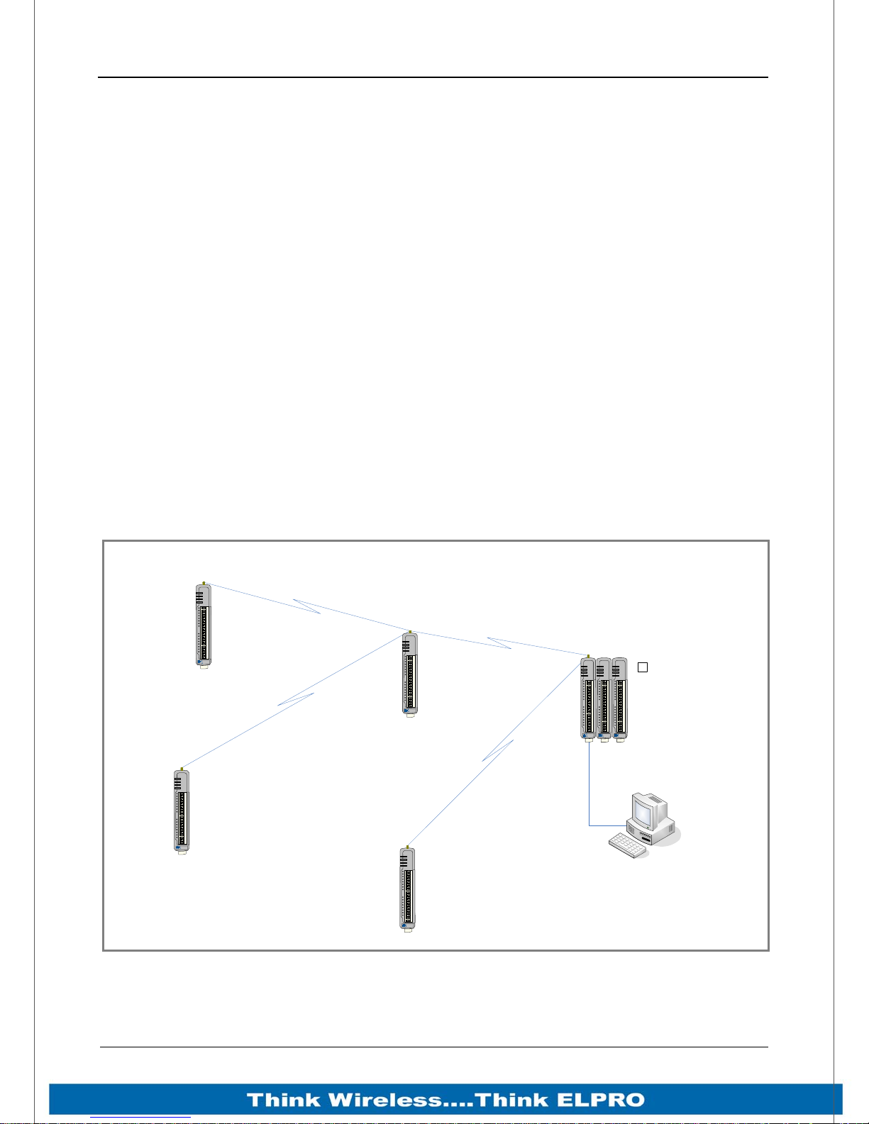
915U-2 Wireless I/O Page 47
4.2.4 Over the Air Web Based Configuration
The 915U-2 modules communicate using Standard Ethernet Protocols which makes it
possible to connect to other 915U-2 module within the radio network for over the air
diagnostics or configuration changes.
A little forethought when designing the system is required as some minor configuration
settings are needed to implement the over air configuration.
The Multi point to point system shown below in Figure 28 will require the following.
Default Gateway address in all remote modules needs to point back to the
Central 915U-2 module radio IP address (i.e. 10.0.0.1)
Central 915U-2 needs to have the “IP Gateway Mode” enabled on the “Mesh”
webpage (see Appendix F: “Web Page Configuration“ for details).
Ethernet IP address range on the remote modules must be different to the
Ethernet IP address range on the Central 915U-2 module or disabled (see
Appendix F: “Web Page Configuration“)
PC must have its Default Gateway address set to the Central 915U-2 Ethernet IP
Address or it must have a route added to its default routing table, e.g. “ROUTE
ADD 10.0.0.0 MASK 255.255.255.0 192.168.1.1
If the system is configured as per above it will allow configuration and diagnostics
access for all remote modules from the PC connected to the Central 915U-2 module.
Over the air Configuration
PWR
RF
232
Default Gateway: 10.0.0.1
Radio: 10.0.0.5
Subnet: 255.255.225.0
Ethernet: 192.168.0.5
Subnet: 255.255.255.0
485
ELPRO
915U-2
PWR
RF
232
485
Default Gateway: 10.0.0.1
Radio: 10.0.0.4
Subnet: 255.255.225.0
Ethernet: 192.168.0.4
Subnet: 255.255.255.0
ELPRO
915U-2
PWR
RF
232
485
ELPRO
915U-2
Default Gateway: 10.0.0.1
Radio: 10.0.0.3
Subnet: 255.255.225.0
Ethernet: 192.168.0.3
Subnet: 255.255.255.0
PWR
RF
232
485
Default Gateway: 10.0.0.1
Radio: 10.0.0.2
Subnet: 255.255.225.0
Ethernet: 192.168.0.2
Subnet: 255.255.255.0
ELPRO
915U-2
CENTRAL 915U-2
PWR
PWR
PWR
Enable IP Gateway Mode
RF
232
485
ELPRO
915U-2
Ethernet: 192.168.1.100
Subnet: 255.255.255.0
Default Gateway: 192.168.1.1 or
A Route Rule , e.g. ROUTE ADD 10.0.0.0
MASK 255.255.255.0 192.168.1.1
√
OK
OK
TX
TX
RX
RX
Radio: 10.0.0.1
Subnet: 255.255.225.0
Ethernet: 192.168.1.1
Subnet: 255.255.255.0
Ethernet IP range must be different to all
other Ethernet Address ranges on the
radio network.
ELPRO
ELPRO
115S-XX
115S-XX
PC
Page 47 915U-2 Wireless I/O
Figure 28 -Over the air Configuration
Page 49
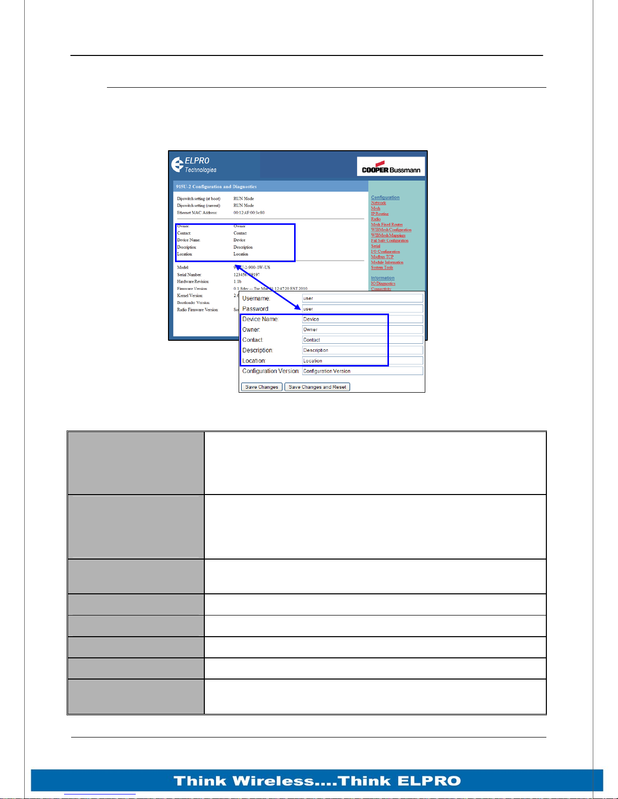
Page 48 915U-2 Wireless I/O
4.3 Module Information Web Page
This Web page is primarily for information purposes. With the exception of the
password, the information entered here is displayed on the home configuration
webpage of the 915U-2.
Username
default = “user”
Password
default = “user”
Device Name
Owner
Contact
Figure 29 – Module Information
Configuration of Username. This is the username used to
access the configuration on the 915U-2. Take care to
remember this username if you change it as it will be needed
to access the 915U-2 in future.
Configuration of Password. This is the password used to
access the configuration on the 915U-2. Take care to
remember this password if you change it as it will be needed
to access the module in future.
A text field if you wish to label the 915U-2. Also name is used
as a DNS Host name with a DHCP Client
A text field for owner name.
A text field for owner phone number, email address etc.
Description
Location
Configuration
Version:
Page 48 915U-2 Wireless I/O
A text field used for a description of the purpose of the unit.
A text field used to describe the location of the 915U-2.
A text field to enter in a version description.
Page 50
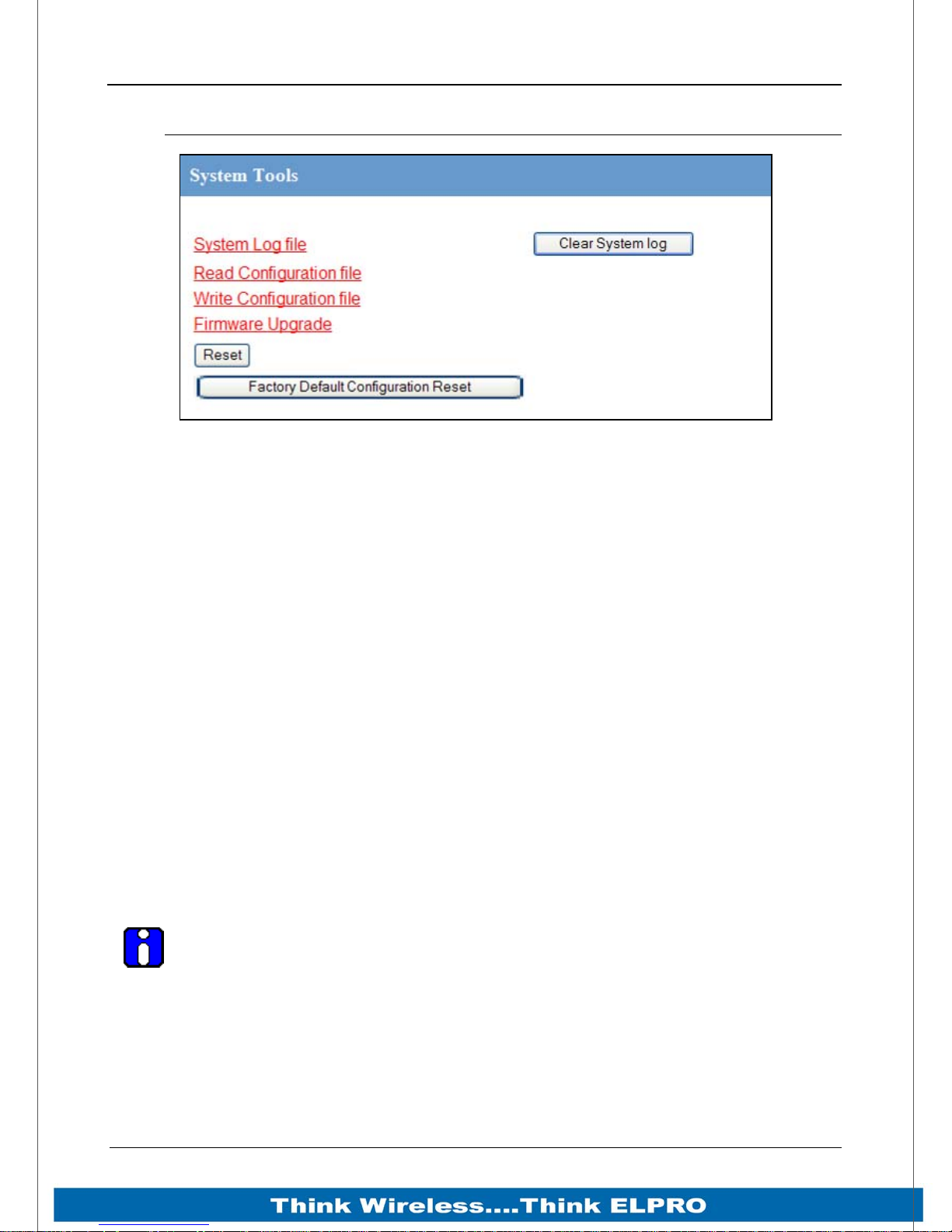
915U-2 Wireless I/O Page 49
4.4 System Tools Web page
Figure 30 – System Tools
System Log File
Logs system instructions, etc to the screen where the log screen can be saved to a file.
Not normally used, however maybe used by Technical Support to diagnose problems.
The “Clear System Log” clears the log screen.
Reading Configuration File
Reads the module configuration into an XML file, which can be saved by selecting
“Save As” from the File menu.
Writing Configuration File
Allows a previously saved XML configuration file to be loaded back into the module.
Firmware Upgrade – Web Page
This option allows the module firmware to be upgraded locally. The process is done by
selecting “Firmware update” and then browsing for the saved firmware file.
Locate and load the firmware file, press the “Send” button which will upload the file to
the module and then press the “Reset” button. The module will do some checks to
ensure the file is valid before a reset can be initiated.
Note: All existing configuration parameters will be saved however if any new
parameters are added to the firmware the default values will be used.
Firmware Upgrade – USB
Firmware can also be upgraded by plugging a USB flash drive with the firmware files
installed into the USB port underneath the “Access Configuration Panel” on the side of
the module. The module will automatically identify that a USB drive has been plugged in
and will initiate the upgrade process.
Page 49 915U-2 Wireless I/O
Page 51
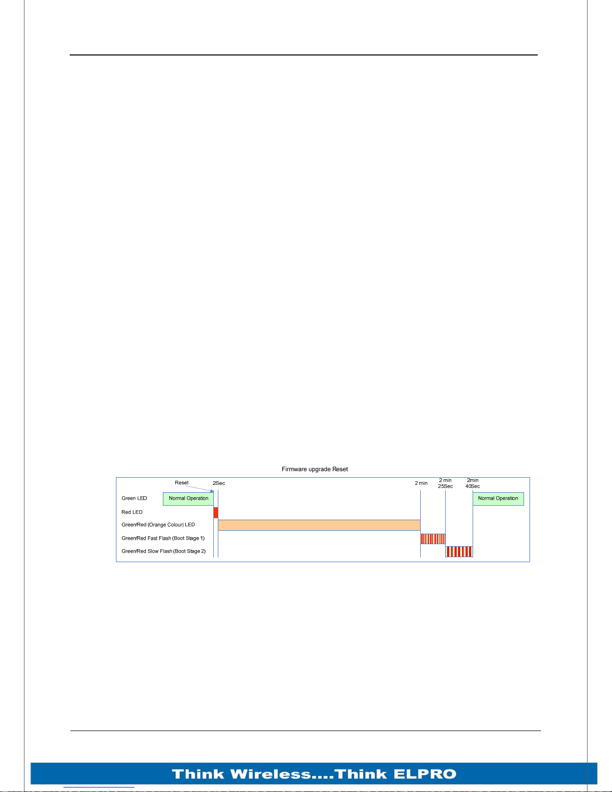
Page 50 915U-2 Wireless I/O
Instructions for upgrading Firmware are as follows.
1. You will need valid ELPRO 915U-2 Firmware upgrade files. Contact ELPRO
Technologies for the latest version. Files must not be renamed, compressed,
or zipped.
2. You will also need a dedicated USB Flash drive which needs to be formatted
and completely free of any other file. Copy the firmware files to the Flash
drive making sure they are in the root of the drive and not in a sub directory.
3. Before upgrading the firmware it is good practice to backup the existing
configuration. Go to the “System Tools” webpage and save the configuration
by selecting “Read Configuration File” and when the XML file is displayed
press <CTRL> F5 to refresh the cache and select “Save As” or “Save Page
As” on the File menu to save the XML as a file.
4. To upgrade, remove the “Configuration Panel” from the side of the module
and plug the Flash drive into the USB port. If the module is mounted on a DIN
rail with other I/O modules it will need to be removed to gain access to the
side panel.
5. Power cycle the module to begin the upgrade process. As the module powers
up it will recognise that a Flash drive has been installed and start upgrading
the firmware. You will see the normal boot up LED sequence (see 3.2
“Indications” for details) however the orange indication will be on for longer.
DO NOT remove the Flash drive or interrupt the power to the module while this
is happening. If the upgrade process is interrupted module could become
unserviceable and will need to be returned to ELPRO for repair.
Upgrade will take approximately 2 minutes and 40 seconds, 120 seconds over
the normal boot time. When update is complete (Solid Green PWR LED
indication) remove the flash drive.
Figure 31 - Firmware Upgrade LED Indications
6. The upgrade process will clear the module flash so you will need to load the
configuration file back into the module. To do this select “Write Configuration
File” from the “System Tools” menu. Browse for the saved XML file and when
loaded press Send and then Reset.
Page 50 915U-2 Wireless I/O
Page 52
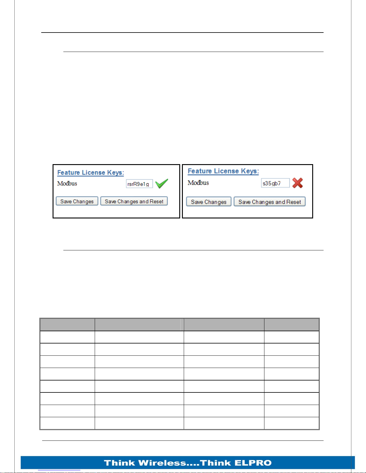
915U-2 Wireless I/O Page 51
4.5 Feature Licence Keys Web Page
Allows the module to be upgraded with enhanced features or upgraded to a more
advanced model .i.e. enabling the Modbus option.
The Feature Licence unlock codes are purchasable by contacting ELPRO Technologies
or your local distributor. The module serial number is needed to generate the Feature
Licence Key which can be found on the default startup web page of the module, for
details on what this looks like see Figure 27 – Main Welcome Screen on page number
46 of this manual.
The upgrade or advanced features are made available by entering in the purchased
“Feature Licence Key” into the appropriate box next to the feature or enhancement.
After entering the code press “Save Changes and Reset”.
The screen will indicate the validity of the code by showing a green tick or a red cross.
Figure 32 - Feature License Keys
4.6 Address Map
The I/O data store provides storage for all I/O data, either local or received from the
system.
The I/O Store provides eight different “data files”, two bit, two word, two long-word and
two floating point files. In addition each file type supports both inputs and outputs of the
device and data storage for the gateway function.
These files are mapped into the address range as described below.
Store name Type Size Address
dot discrete outputs 3000 (bits) 00001
din discrete inputs 2500 (bits) 10001
ain word inputs (16-bit) 2500 (words) 30001
aot word outputs(16-bit) 2500 (words) 40001
pin long inputs (32-bit) 20 (longwords) 36001
real_ain float inputs (32-bit) 20 (floats) 38001
pot long outputs (32-bit) 20 (longwords) 46001
real_aot float outputs (32-bit) 20 (floats) 48001
Page 51 915U-2 Wireless I/O
Page 53
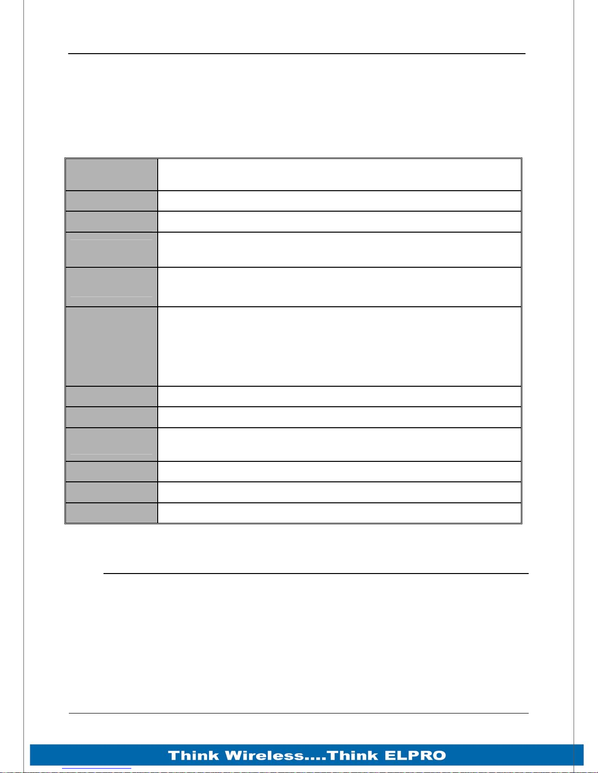
Page 52 915U-2 Wireless I/O
The addressing utilises standard Modbus protocol formatting as well as being common
for ELPRO protocol.
The following table shows the basic onboard I/O available in a standard 915U-2 module
with no expansion I/O connected. For a more detailed I/O map (showing the full register
range), see Appendix B: “I/O Store Registers” at the end of the manual.
4.6.1 Standard 915U-2 I/O (Basic I/O)
Address Input / Output Description
0001 - 0008
10001 - 10008
10009 - 10020
30001 - 30004
30005
30006
30007
30008
30009 - 30012
30013 - 30016
36001 - 36008
38000 - 38021
Local DIO1 – DIO8 (as Outputs)
Local DIO1 – DIO8 (as inputs)
Setpoint status from Analog inputs 1 through 12. (AI1, 2, 3, 4
Current Mode), (Internal Supplies), (AI1, 2, 3, 4 Voltage Mode)
Local AI1 – AI4. (Current Mode)
( AI1, AI2 4-20mA diff, AI3, AI4 4-20mA Sink)
Local Supply voltage (8-40V default scaling)
Local 24V loop voltage (8-40V default scaling)
Local Battery voltage (8-40V default scaling)
115S Expansion I/O Supply Voltage (8-40V default scaling)
Local AI1 – AI4. (Voltage Mode) ( AI1, AI2 0-10V, AI3, AI4 0-5V)
Local Pulse rate inputs PI1 – PI4
Local Pulsed input counts – (PI1 Most significant word is 36001 and
Least significant word is 36002)
Local Analog inputs as Floating point values (mA, Volts or Hz)
40001 - 40002
48001 - 48002
Local AO1 – AO2
Local AO1 – AO2 as floating point values (mA)
4.7 Serial Expansion I/O
4.7.1 Adding modules
Additional 115S serial expansion I/O modules can be added if more I/O is required.
When connecting expansion I/O module to the 915U-2 the RS485 serial port is
configured to communicate ELPRO protocol by default.
The default serial parameters of the RS485 port are 19200, N, 8, 1 which match the
defaults of the 115S serial expansion modules. The parameters can be changed, to
Page 52 915U-2 Wireless I/O
Page 54
915U-2 Wireless I/O Page 53
increase poll speeds in larger systems however the serial modules will need to match
that of the 915U-2 RS485 port.
Also if more than 3 serial expansion modules are added the “Maximum Connections” for
the RS485 port on the “Serial” page will need to be adjusted.
Note: Reducing the “Maximum connections” will slightly improve the serial scan
time however make sure the slave addresses falls within the “Maximum
connections”. If the Slave address is above the “Maximum connections”, it will
not be polled.
Next, connect the serial expansion module and take note of the module address (Rotary
switches on the bottom) as this address will be used as an offset to locate the I/O within
the 915U-2.
Also make sure the last module in the RS485 loop has the termination switch on
(down).
Failure to terminate the RS485 correctly will result in the modules not operating
correctly.
4.7.2 115S Expansion I/O Memory Map
I/O data on the 115S module is read into memory locations according to their Modbus
address. The maximum number of Modbus addresses is 24.
Each 115S module has an “Offset” which applies to the location of all of its registers.
This Offset is equal to the units Modbus address multiplied by 20.
If the modules Modbus address is 15, the Offset value will be 15 X 20 = 300.
E.g. If connecting a 115S-11 (16 x DIO) with address #15
Digital input 1 will be at register location 10301.
Digital Output 1 will be at register location 301
If using a 115S-12 (8 x DIO & 8 AIN) with address 16
Digital input 1 will be at register location 10321
Analog input 1 will be at register location 30321
See Appendix C: “Expansion I/O Store Registers”. For a more detailed address map of
the serial expansion I/O modules.
Page 53 915U-2 Wireless I/O
Page 55
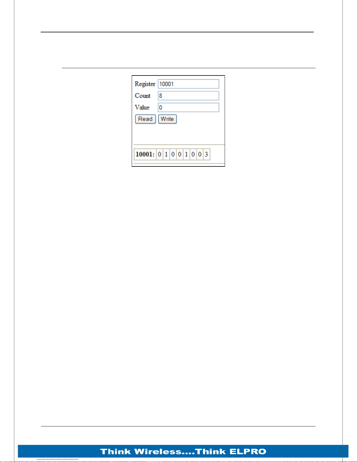
Page 54 915U-2 Wireless I/O
Chapter 5 - Diagnostics
5.1 IO Diagnostics
Figure 33- I/O Diagnostics
Selecting this option from the main screen will allow some basic reading and writing of
the I/O store registers within the module.
To read a register location, enter an address location, e.g. 10001 (for digital Inputs),
enter a count (number of consecutive registers) and then press the “Read” button
Below the buttons, you will see the returned address location and the returned values
To “Write” to outputs, enter the address location, count, and value and then press the
“Write” button.
You will then see the outputs change to the value you entered.
E.g. Write to Register 1 with a count of 8 and a value of 1 will turn all the Local Digital
Outputs on.
Write to Register 40001 with a count of 2 and a value of 49152 will turn all the Local
Digital Outputs on.
Note: If when reading a register and getting the symbol “–“this indicates that the register
has not been written to and so it has no value (not even zero).
Note: if there is a mapping configured and any one of the source register values has a
“–“ the mapping will not be sent (see section 0“Invalid” register state” for more details.
A mapping will only be sent when all registers have a value.
Using the I/O Diagnostics you can check the register locations for these “-“ values and
even write values if required.
If when reading the Status of the DIO on the module you see the value “3”, this
indicates that the DIO is being used as an output in the “ON” state.
Page 54 915U-2 Wireless I/O
Page 56
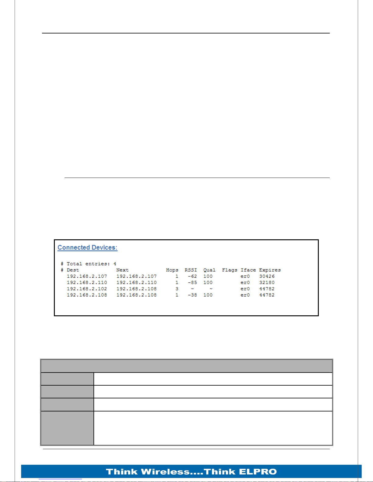
915U-2 Wireless I/O Page 55
5.1.1 Modbus Error Registers
Each of the Expansion I/O modules have diagnostics registers that can indicate any
Modbus Errors, Codes, Counts, etc.
30017 + Offset = Modbus Error Counter (number of errors the modules has had)
30018 + Offset = Modbus Last Error Code (see Appendix D for codes)
30019 + Offset = Modbus Lost Link Counter (number of Communication Errors)
30020 + Offset = Modbus Module Type
dec 257 (101hex) indicates a 115S-11
dec 513 (201hex) indicates a 115S-12
dec 769 (301hex) indicates a 115S-13
5.2 Connectivity
The Connectivity webpage displays connections and available networks. The
“Connected Devices” section displays the radio channel, received signal strength, and
radio data rate for each Client or Access Point by their MAC Address. The readings
shown are based upon the last received data message from the Access Point or Client.
Client stations also display a list of detected Access points (Site Survey), including
network name (SSID), channel and maximum data rate.
Note that when updating the Connectivity webpage, it is necessary to hold down the
<ctrl> key while pressing the refresh button. Otherwise, the information will not be
updated.
Dest
Next
Hops
RSSI
Page 55 915U-2 Wireless I/O
Destination IP Address
Next IP Address
Number of Hops
RSSI (Radio Signal Strength Indication) measured in dBm which is a
negative value scaled from -30dBm (good) to -120dBm (bad). RSSI is
displayed for destination addresses, which are direct neighbours. If the
Destination IP is not the next hop, you will see an RSSI value of “~”
Figure 34 - Connectivity
Description
Page 57
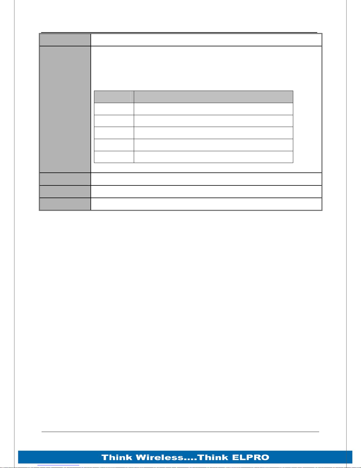
Page 56 915U-2 Wireless I/O
which indicates no direct link to that station.
The LQI is a logarithmic representation of the number of bit errors in the
frame that were corrected by the Forward Error Correction algorithm.
Each data bit is encoded with 7 forward error correction bits, so a 100
byte frame contains 100 * 8 bits / byte * 7 FEC bits/bit = 5600 bits. (see
below this table for details)
Qual
(Link Quality
Index)
LQI Description
100 No Errors (or better than 1 in 100,000)
80 1 in 10,000 raw bit errors
60 1 in 1000 raw bit errors
40 1 in 100
20 1 in 10.
Flags
Iface
Expires
Addition indications for this entry
The connection interface (er0 = Ethernet radio, eth0 = Ethernet LAN)
This is the timeout in msec for the entry
LQI (Link Quality Indication)
Because a typical frame is around 80 bytes (4480bits), you should not normally
see any readings between 75 and 99.
Communication becomes unreliable with LQI around 30.
As the LQI drops below 25, nearly every frame will have enough bit errors that
the FEC will no longer be able to recover the original data, so the frame will be
corrupted. Hence you will hardly ever see a reading below 25.
With signal strength (RSSI) -100 dBm or better, the LQI should always read 100.
You should expect LQI readings below 100 with signal strength -105 dBm or
worse.
If you have good signal strength and are getting LQI readings less than 100, this
is a sign of interference, or of a problem with the radio of the unit you are using.
Page 56 915U-2 Wireless I/O
Page 58
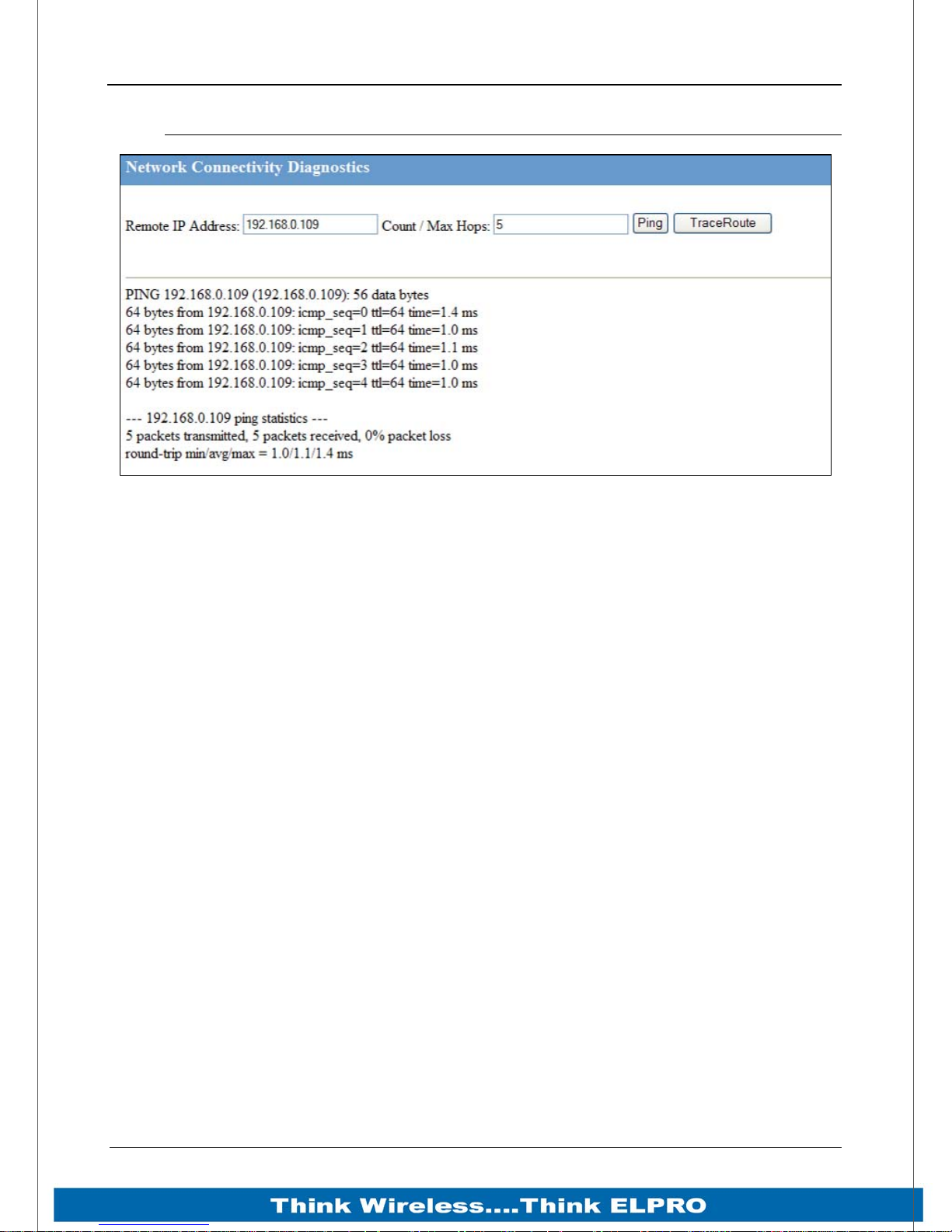
915U-2 Wireless I/O Page 57
5.3 Network Diagnostics
Figure 35 – Network Diagnostics
Network Diagnostics allows you to check the communications path to other modules
within the system.
There are two options for checking the communications.
Ping
Ping is a standard Network instruction that sends out a small data probe to the IP
address configured letting you know if you have a communication path or not.
You will receive a response for each Ping, which will show a packet size, IP Address,
Sequence number and a time in milliseconds.
Followed by a summary showing the number of packets transmitted, the number of
packets received, any lost packets and the Minimum, Average and Maximum Ping times
in milliseconds.
A Ping can be done on either the Radio Network or Ethernet Network. The ping
command will automatically select the correct network interface according to the
address selected.
Remote IP Address – This is the IP address that you want to Ping
Count / Max Hops – This is the number of Ping probes that are send out. You should
see this many responses come back.
Page 57 915U-2 Wireless I/O
Page 59
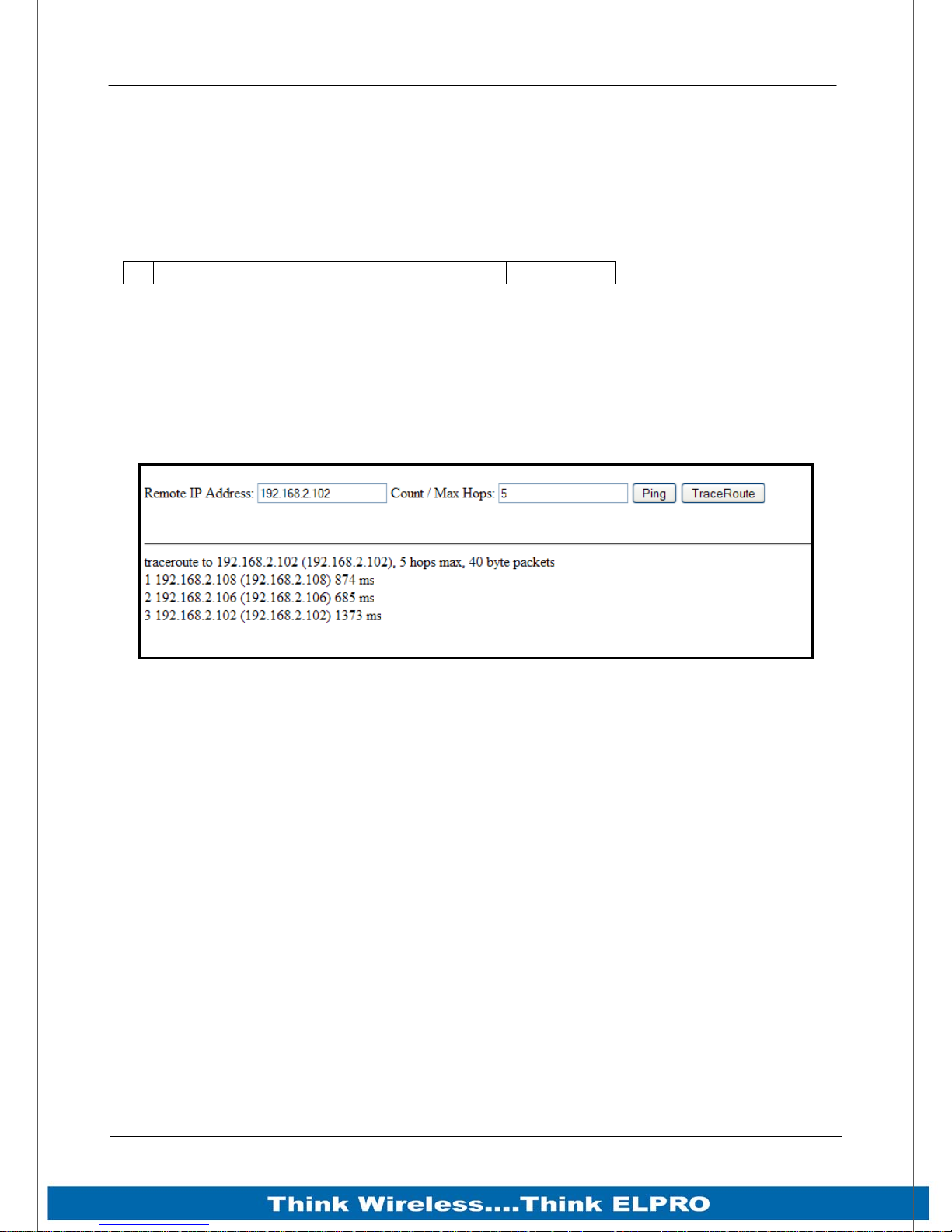
Page 58 915U-2 Wireless I/O
Trace Route
Because the modules use the AODV protocol which is a routing protocol capable of
finding its own path through the network it can be difficult to determine the selected
communications path.
“Trace Route” allows you to trace the communications path through the network.
Example from the screen shot below:
1 192.168.2.108 (192.168.2.108) 874 ms
“1” = Hop number
“192.168.2.108” = DNS Name of the device.
“(192.168.2.108)” = IP Address of the device.
“874 ms” = A roundtrip response time (ping) in milliseconds from the Local IP to each
hop point.
Figure 36 – Trace Route
E.g. The above example shows the Ping time from the Host to the first IP address
(192.168.0.102) is 874 msec, The jump from Hop1 (192.168.0.108 to Hop2
(192.168.0.106) is 685msec, etc.
Page 58 915U-2 Wireless I/O
Page 60
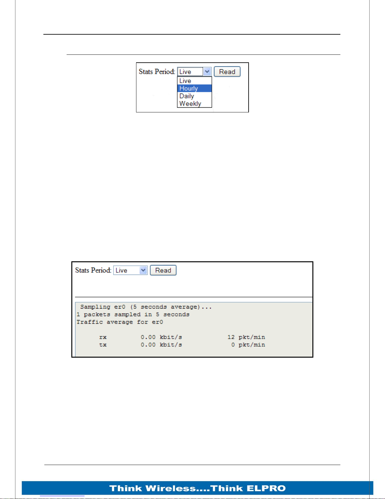
915U-2 Wireless I/O Page 59
5.4 Network Statistics
Figure 37 – Network Statistics Period
After enabling the “Gather Statistics” on the Main Network page, this page will display
the average Receive and Transmit traffic throughput over a configured time period.
From the drop down “Stats Period”, select the appropriate sample period then press the
“Read” button.
The following is a list of available sample periods and what will be displayed:
Live, this will display the average Transmit and Receive data through put in kbit/s and
the number of data packets seen on the radio interface (er0), displayed in packet pre
minute.
Figure 38 – Network Statistics
Page 59 915U-2 Wireless I/O
Page 61
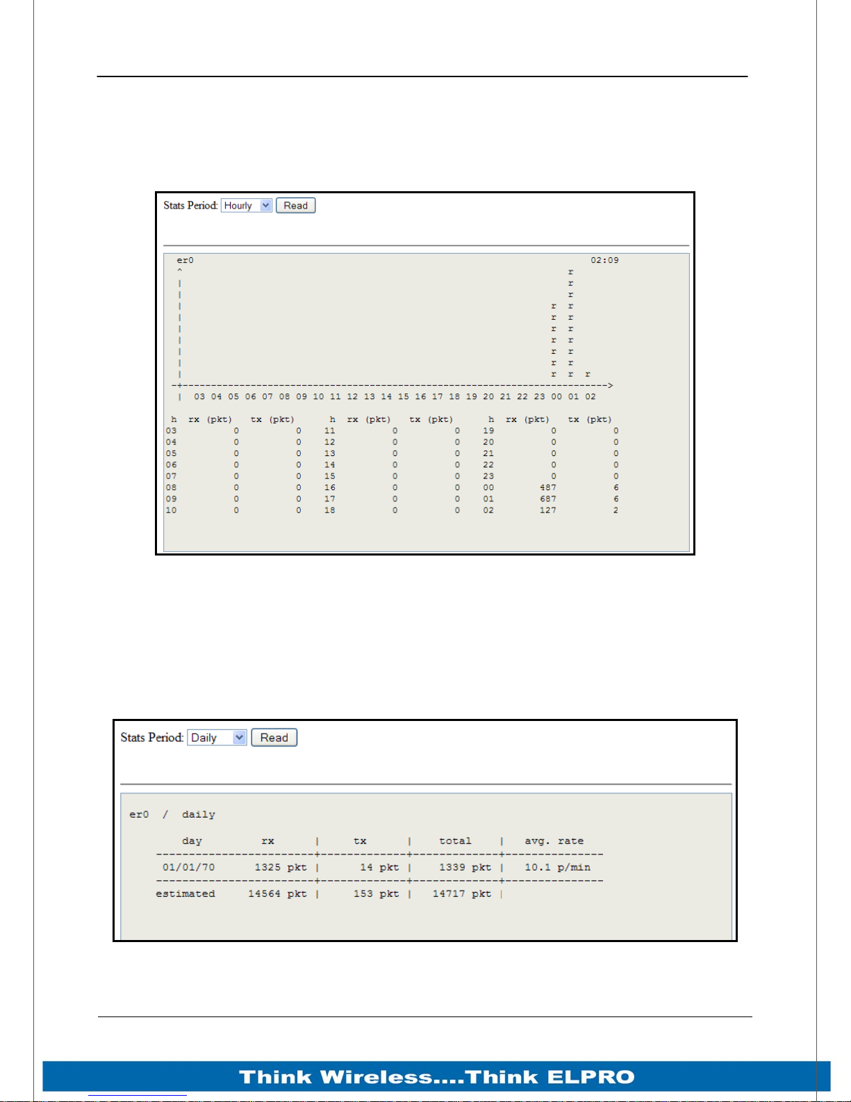
Page 60 915U-2 Wireless I/O
Hourly, this will display a graph showing overall transmit (t) and Receive (r) data on an
hourly scale in accordance with the module Date and time stamp. (“rt” indicate both
Transmit and Receive)
Below the graph is a table showing the average data throughput (in packets) for
transmit and receive and for each hour.
Figure 39 – Hourly Statistics
Daily and Weekly, period shows the average throughput over the daily or weekly time
period.
Also shows the average number of packet received (rx) and Transmitted (tx) as well as
the total.
Average is an estimated value based on the amount of data gathered in the time
available.
Figure 40 –Daily/Weekly Statistics
Page 60 915U-2 Wireless I/O
Page 62
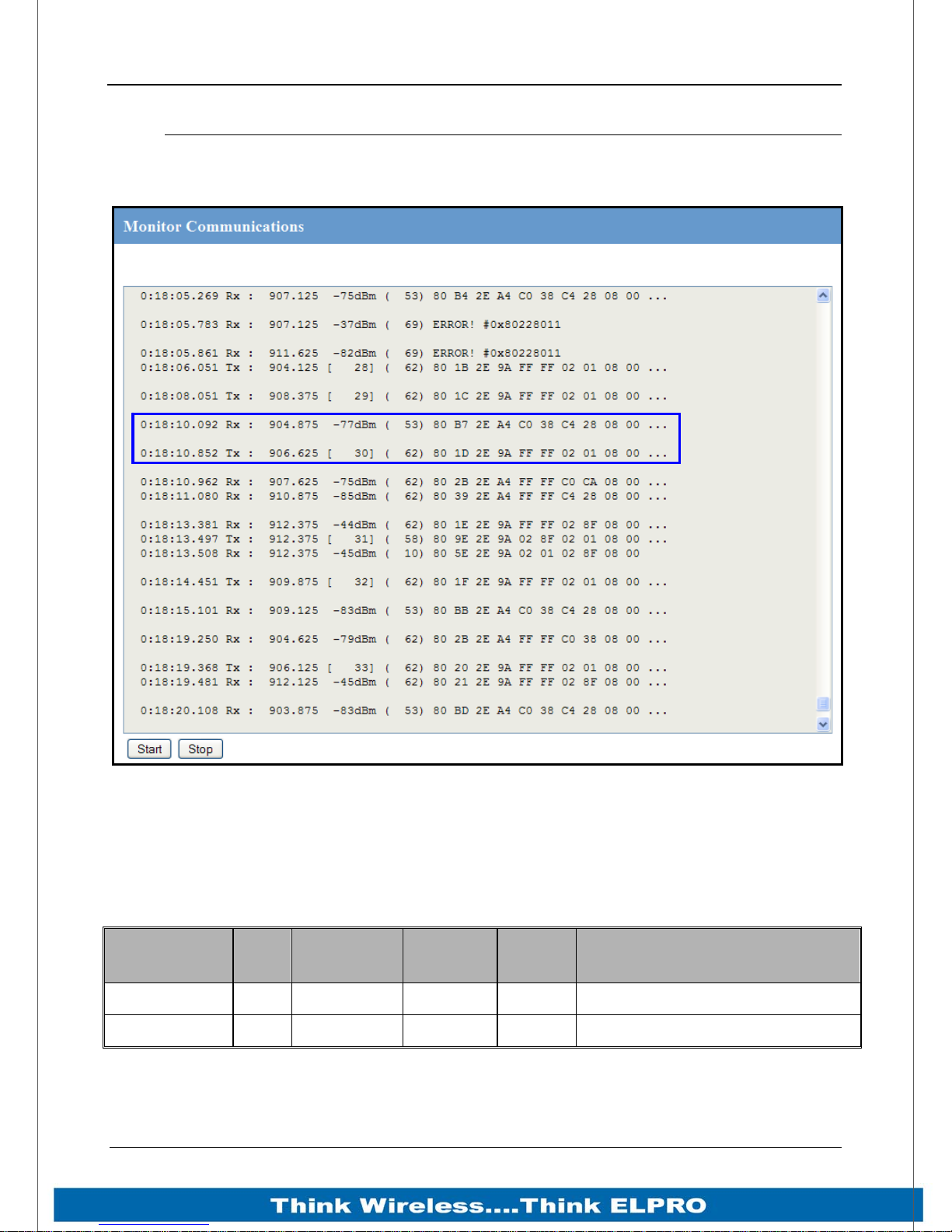
915U-2 Wireless I/O Page 61
5.5 Monitor Radio Comms
The Monitor Comms page shows radio communication frames that are received or
transmitted by the radio.
Figure 41 - Monitor Comms
The Table below shows some data frames from the communication log screen above.
Below that is another table explaining each of the field within the data frame.
Corrupted data frames are shown with an “ERROR!” in the frame.
Time
0:18:10.092 Rx : 904.875 -77dBm ( 53) 80 B7 2E A4 C0 38 C4 28 08 00
0:18:10.852 Tx : 906.625 [ 30 ] ( 62 ) 80 1D 2E 9A FF FF 02 01 08 00
Page 61 915U-2 Wireless I/O
TX/
RX
Frequency
Signal
Level
Data
Length
Data
Page 63
Page 62 915U-2 Wireless I/O
Time
TX/RX
Frequency
Signal
Level
Data
Length
Data
Time stamp indicating the time from when the module was turned on.
Indicates whether the message is received or transmitted
Shows the Frequency of the RX/TX frame
Shows the Receive Signal Level on any received message or internal
sequence number for the transmitted message.
Total length of the transmitted or received message
The TX Data frame from above is dissected below
First two bytes (80 11) = Frame Flags
Second two bytes (2E 9A) = Network Address
Third two bytes (FF FF) = Destination Address, (FFFF is A broadcast
address)
Fourth two bytes (02 01) = Source Address (Convert each byte to decimal
and they will be the last two bytes of the Radio IP address.)
Fifth two bytes (08 00) = EtherType flag (Internet Protocol, Version 4)
Page 62 915U-2 Wireless I/O
Page 64
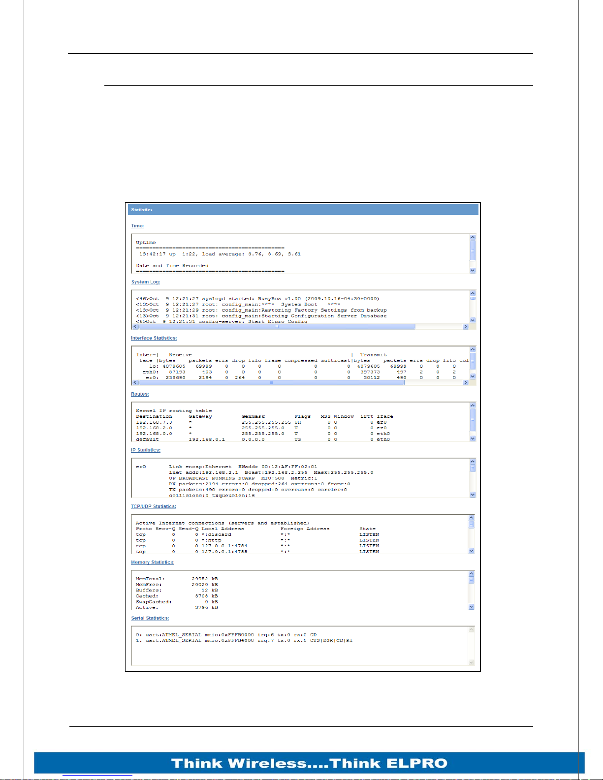
915U-2 Wireless I/O Page 63
5.6 Statistics
The Statistics webpage is used for advanced debugging of 915U-2. This webpage
details the state of the 915U-2 and performance information.
The page is useful to ELPRO technical support personnel in diagnosing problems with
the module.
Note that when updating the Statistics webpage, it is necessary to hold down the <ctrl>
key while pressing the refresh button. Otherwise, the information will not be updated.
Page 63 915U-2 Wireless I/O
Figure 42 – Module Statistics
Page 65
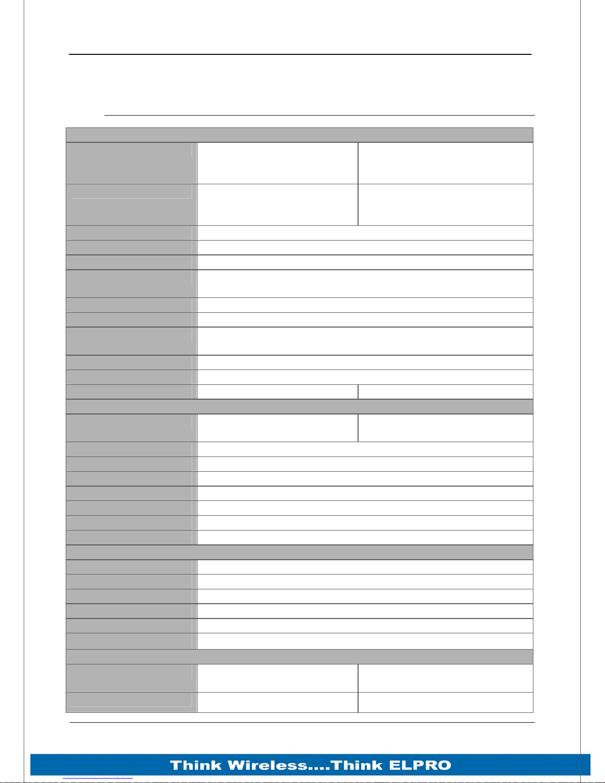
Page 64 915U-2 Wireless I/O
Chapter 6 - Specifications
6.1 Specifications
General
EMC specification
Radio specification
Emission designator
Hazardous Spec
IP Rating
Housing
Mounting
Terminal blocks
LED indication
Operating Temp
Humidity
Weight
Power Supply
Battery supply
AC Supply
Solar Supply
Analog Loop Supply
Static Current Drain
TX Current drain
Batt charging current
Operating Frequency
Channels / Hop-sets
Line of Site Range
Antenna Connector
Radio data rate
Transmit power
Modulation
FCC Part 15
EN 300 683
AS 3548
FCC Part 15.427
AS 4268.2
RFS29 NZ
160KF1D
Class 1 Div 2 Hazardous Areas - (pending)
IP40
High Density Thermo-Plastic
5.91”x 7.09” x 1.38” (170 x 150 x 33 mm)
DIN Rail mounting
Removable Terminals up to 12 gauge (2.5mm2) conductors
Power, RF, RS232, and RS485 serial, I/O. Ethernet Link and
100Mbit indication
-40 to +140 °F, -40 to +60°C,
99% RH non-condensing
1.1 lb (500gm) 1.3lb (600gm) boxed
Power Supply
15 to 30VDC Overvoltage and Reverse
12 to 15VDC
N/A
2 Watt solar option (Factory fitted)
24VDC 150mA
220mA
500mA
1.0 Amp nominal
Radio Transceiver
902 – 928 MHz
50 channels, 2 hop sets
15 mile LOS (USA / Canada) 12km LOS (Australia/ NZ)
SMA Female
19200 baud
Transmitter
1W
1W
FSK
FCC Part 90
89/336/EEC
voltage protected
USA/Canada 4W EIRP
Australia / NZ 1W EIRP
Page 64 915U-2 Wireless I/O
Page 66
915U-2 Wireless I/O Page 65
Receiver
RX Sensitivity
-109dBm FER = 12%
Serial Ports
RS232 Port
RJ45 to EIA-562 specification
RS485 Port
Data rates
Parity
Stop Bits
DIO
DI On-state Voltage
Wetting Current
Max I/P Pulse Rate
Min I/P Pulse Width
DO Max voltage
DO Max current
Max Pulse out Rate
Analog Input
Current Range
Current Resolution
Voltage Range
Voltage Resolution
Input Impedance
AI1, AI2 (to common)
Input Impedance
AI3, AI4 (V)
Input Impedance (I)
Calibrated Accuracy
Analog Output
Current Range
Current Resolution
Calibrated Accuracy
Encryption
User Configuration
2 pin terminal block
110 – 230400 baud
Odd, Even, None.
1,2,
Digital Inputs/Outputs
8 x
<2.1VDC
5mA
DI 1 & 2 = 50KHz, DI 3 & 4 = 1KHz
100uSec using TTL pulsed inputs
30VDC
200mA
1 KHz
Analog Input / Outputs
2 x Differential 2 x Single Ended
0-24mA 0-24mA
14bit 13bit
AI 1 & 2 = 0-25V AI 3 & 4 = 0-5V
13bits
55K ohm
25 K ohm
100 ohm
0.1%
2 x 24mA sourcing outputs
0-24mA
15 bits
0.1%
System Parameters
ELPRO 64 bit Proprietary 128 bit AES
Web page and Software Configuration
Page 65 915U-2 Wireless I/O
Page 67
Page 66 915U-2 Wireless I/O
Appendix A: dBm to mW conversion table
dBm to mW Conversion
Watts dBm Watts dBm
10 mW 10 dB 200 mW 23 dB
13 mW 11 dB 316 mW 25 dB
16 mW 12 dB 398 mW 26 dB
20 mW 13 dB 500 mW 27 dB
25 mW 14 dB 630 mW 28 dB
32 mW 15 dB 800 mW 29 dB
40 mW 16 dB 1.0 W 30 dB
50 mW 17 dB 1.3 W 31 dB
63 mW 18 dB 1.6 W 32 dB
80 mW 19 dB 2.0 W 33 dB
100 mW 20 dB 2.5 W 34 dB
126 mW 21 dB 3.2 W 35 dB
158 mW 22 dB 4.0 W 36 dB
Page 66 915U-2 Wireless I/O
Page 68
915U-2 Wireless I/O Page 67
Appendix B: I/O Store Registers
“Output Coils”
0001
0008
0009
0020
0021
0040
0041
0500
0501
3000
3001
10000
Local DIO1 – DIO8 (as Outputs) at address 1-8.
Spare
Locally attached 115S modules DIO Outputs
(See 115S detail below)
(space for up to 24 115S modules – 20 registers for each module)
General Purpose Bit Storage – Used for:
Staging area for data concentrator
Fieldbus Mappings storage
Force Mapping registers (assigned in Config)
Not Available
“Input Bits”
10001
10008
10009
10020
10021
10040
10041
10500
10501
12500
12501
30000
Local DIO1 – DIO8 (as inputs) at address 1-8.
Setpoint status from Analog inputs 1 through 12.
Locally attached 115S modules DIO Inputs
(See 115S detail below)
(space for up to 24 115S modules)
General Purpose Bit Storage – Used for:
Staging area for data concentrator
Fieldbus Mappings storage
Not Available
Page 67 915U-2 Wireless I/O
Page 69
Page 68 915U-2 Wireless I/O
“Input Registers”
30001
30004
30005
30006
30007
30008
30009
30012
30013
30016
30018
30020
30021
30040
30041
Local AI1 – AI4. (Current Mode)
( AI1, AI2 4-20mA differential, AI3, AI4 4-20mA Sink)
Local Supply voltage (8-40V scaling)
Local Battery voltage
Local 24V loop voltage
115S Supply Voltage
Local AI1 – AI4. (Voltage Mode)
( AI1, AI2 0-10V, AI3, AI4 0-5V)
Local Pulse rate inputs PI1 – PI4
Spare
Locally attached 115smodules
(See 115S detail below)
30500
30501
32500
32501
36000
36001
36008
36009
36040
36041
38000
38001
38032
(space for up to 24 115S modules)
General Purpose word Storage – Used for:
Staging area for data concentrator
Fieldbus Mappings storage
Not Available
Local Pulsed inputs 1-4.B.E Format.
Most significant word at lower / odd address.
spare
Not Available
Local Analog inputs as floating point values
Modscan Format (Sign + Exponent + Most significant 7 bits of
significant at Even / Higher Addressed location. Lower 16 bits of
Significant at lower / Odd addressed location)
(12.3 => 38001=CCCD, 38002=4144)
Page 68 915U-2 Wireless I/O
Page 70
915U-2 Wireless I/O Page 69
38033 - 38040
32501
40000
Spare space for floating point values
Not Available
“Holding Registers”
40001
40002
40003
40020
40021
40040
40041
40500
40501
Local AO1 – AO2
Spare
Locally attached 115S modules
(See 115S detail below)
(space for up to 24 115S modules)
General Purpose word Storage – Used for:
42500
42501
46000
46001
46008
46009
46040
46041
48000
48001
48004
Staging area for data concentrator
Fieldbus Mappings storage
Not Available
Local Pulsed Outputs 1-4. B.E Format.
Most significant word at lower / odd address.
spare
Not Available
Local Analog outputs as floating point values
Modscan Format (Sign + Exponent + Most significant 7 bits of
significand at Even / Higher Addressed location. Lower 16 bits of
significand at lower / Odd addressed location)
(12.3 => 48001=CCCD, 48002=4144)
48005
48040
48041
onwards
Page 69 915U-2 Wireless I/O
Spare space for floating point values
Not Available
Page 71

Page 70 915U-2 Wireless I/O
Appendix C: Expansion I/O Store Registers
To calculate the I/O Store register you need to find the address of the I/O point
from the module tables below and then add the offset.
The Offset is the Modbus address multiplied by 20.
E.g1. Digital input #1 on an 115S-11 with address 5 would be: (5x20) +10001 =
100+10001 = 10101
E.g2. Digital output #2 on an 115S-11 with address 6 would be: (6x20) +2 =
120+2= 122
E.g3. Analog input #3 on an 115S-12 with address 3 would be: (3x20) +30003 =
60+30003 = 30063.
E.g4. Analog Output #8 on an 115S-13 with address # 7 would be: (7x20) +
40007 = 140+40007 = 40147
Page 70 915U-2 Wireless I/O
Page 72
915U-2 Wireless I/O Page 71
I/O store for a 115S-11 Expansion I/O module
0001 + Offset
0016 + Offset
0017 + Offset
0020 + Offset
10001 + Offset
10016 + Offset
10017 + Offset
10018 + Offset
10019 + Offset
10020 + Offset
30001 + Offset
30004 + Offset
30005 + Offset
30012 + Offset
30013 + Offset
30016 + Offset
DIO Outputs 1 - 16
Spare
DIO Inputs 1 - 16
Spare
Modbus Error indication for this 115S module
Detected indication for this 115S module
115S-11 pulsed input rate 1 – 4
115S-11 Pulsed input count
Spare
30017 + Offset
30018 + Offset
30019 + Offset
30020 + Offset
40001 + Offset
40008 + Offset
40009 + Offset
40016 + Offset
40017 + Offset
40020 + Offset
Modbus Error Counter for this 115S module
Modbus Last Error Code for this 115S module
Modbus Lost Link Counter for this 115S module
Module type (0x0101) = 257. / Error Status
Spare
Pulsed Output target 1 – 8 (1 register per pulsed output)
Spare
Page 71 915U-2 Wireless I/O
Page 73
Page 72 915U-2 Wireless I/O
I/O store for a 115S-12 Expansion I/O module
0001 + Offset
0008 + Offset
0009 + Offset
0020 + Offset
10001 + Offset
10008 + Offset
10009 + Offset
10018 + Offset
10019 + Offset
10020 + Offset
30001 + Offset
30008 + Offset
30009 + Offset
30016 + Offset
30017 + Offset
DIO Outputs 1 - 8
Spare
DIO Inputs 1 - 8
Spare
Modbus Error indication for 115S module
Detected indication for this 115S module
Inputs AIN 1 – AIN8
Spare
Modbus Error Counter for this 115S module
30018 + Offset
30019 + Offset
30020 + Offset
40001 + Offset
40008 + Offset
40009 + Offset
40016 + Offset
40017 + Offset
40020 + Offset
Modbus Last Error Code for this 115S module
Modbus Lost Link Counter for this 115S module
Module type (0x0201) = 513. / Error Status
Spare
Pulsed Output target 1 – 8 (1 register per output)
Spare
Page 72 915U-2 Wireless I/O
Page 74
915U-2 Wireless I/O Page 73
I/O store for a 115S-13 Expansion I/O module
0001 + Offset
0008 + Offset
0009 + Offset
0020 + Offset
10001 + Offset
10008 + Offset
10009 + Offset
10018 + Offset
10019 + Offset
10020 + Offset
30001 + Offset
30016 + Offset
30017 + Offset
30018 + Offset
DIO Outputs 1 - 8
Spare
DIO Inputs 1 - 8
Spare
Modbus Error indication for 115S module
Detected indication for this 115S module
Spare
Modbus Error Counter for this 115S module
Modbus Last Error Code for this 115S module
30019 + Offset
30020 + Offset
40001 + Offset
40008 + Offset
40009 + Offset
40016 + Offset
40017 + Offset
40020 + Offset
Modbus Lost Link Counter for this 115S module
Module type (0x0301) = 769. / Error Status
Analog Output 1 – 8
Pulsed Output target 1 – 8 (1 register per pulsed output)
Spare
Page 73 915U-2 Wireless I/O
Page 75

Page 74 915U-2 Wireless I/O
Appendix D: Modbus Error Codes
Code Name Meaning
The function code received in the query is not an allowable
action for the server (or slave). This may be because the
0
02
Illegal
Function
Illegal Data
Address
function code is only applicable to newer devices, and was not
implemented in the unit selected. It could also indicate that the
server (or slave) is in the wrong state to process a request of
this type.
The data address received in the query is not an allowable
address for the server (or slave). More specifically, the
combination of reference number and transfer length is invalid.
For a controller with 100 registers, the PDU addresses the first
register as 0, and the last one as 99. If a request is submitted
with a starting register address of 96 with a quantity of 4
registers, then this request will successfully operate on
registers 96, 97, 98, 99. If a request is submitted with a starting
register address of 96 and a quantity of registers of 5, then this
request will fail with Exception Code 0x02 “Illegal Data
Address”.
03
04
05
06
Illegal Data
Value
Slave Device
Failure
Acknowledge
Slave Device
Busy
A value contained in the query data field is not an allowable
value for server (or slave). This indicates a fault in the structure
of the remainder of a complex request, such as that the implied
length is incorrect. It specifically does NOT mean that a data
item submitted for storage in a register has a value outside the
expectation of the application program, since the MODBUS
protocol is unaware of the significance of any particular value
of any particular register.
An unrecoverable error occurred while the server (or slave)
was attempting to perform the requested action.
Specialized use in conjunction with programming commands.
The server (or slave) has accepted the request and is
processing it, but a long duration of time will be required to do
so. This response is returned to prevent a timeout error from
occurring in the client (or master).
Specialized use in conjunction with programming commands.
The server (or slave) is engaged in processing a long–duration
program command. The client (or master) should retransmit
the message later when the server (or slave) is free.
08
Page 74 915U-2 Wireless I/O
Memory
Parity Error
Specialized use in conjunction with function codes 20 and 21
and reference type 6, to indicate that the extended file area
failed to pass a consistency check.
Page 76
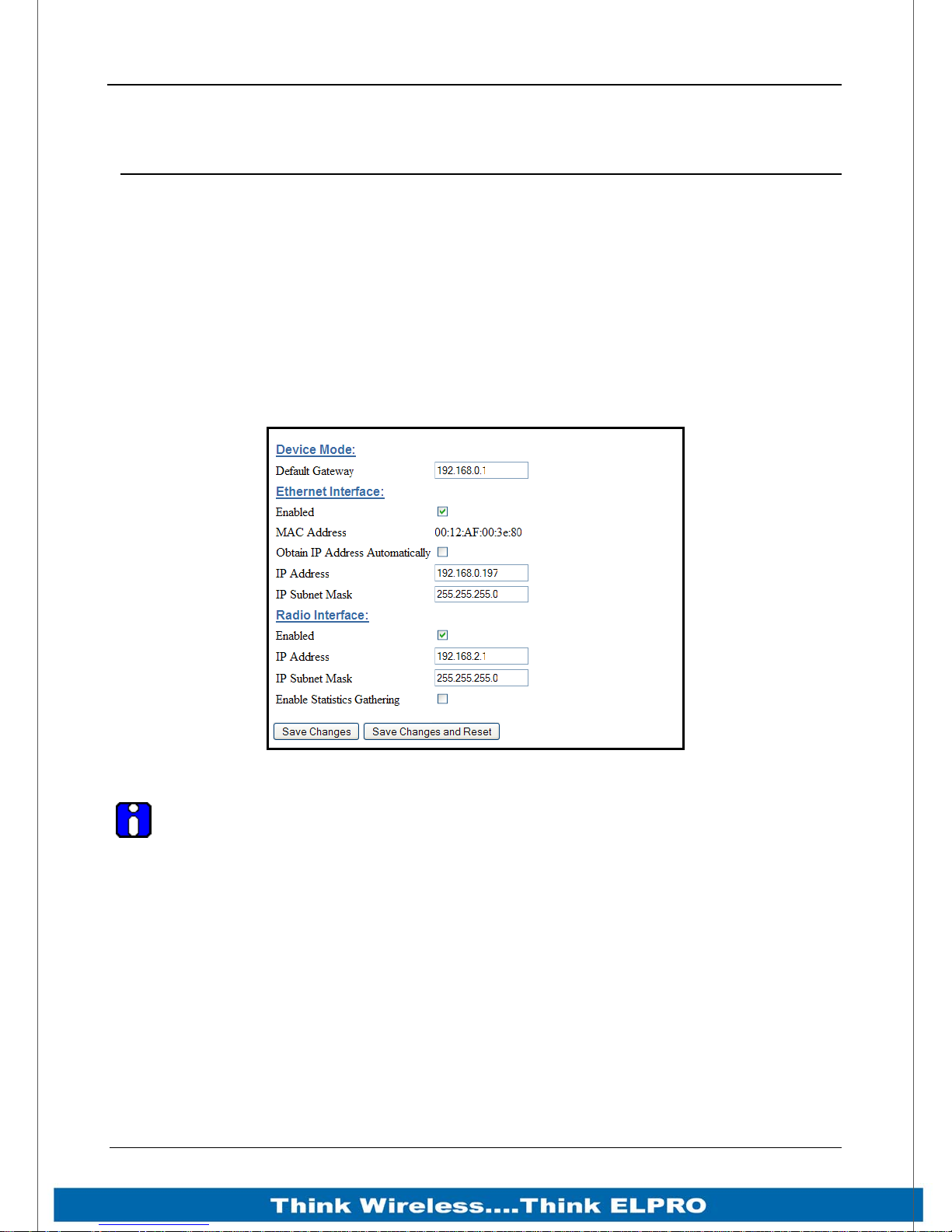
915U-2 Wireless I/O Page 75
Appendix E: Web Page Configuration
Network Configuration
You can view or modify Ethernet network parameters by selecting the “Network” menu.
When prompted for username and password, enter “user” as the username, and “user”
as the password in the password field (This is the factory default – See section 4.3
”Module Information ” to change). If you have forgotten the IP address or password, the
Factory Default switch may be used to access the existing configuration. Refer to
section above for this procedure.
The Network Configuration page allows configuration of parameters related to the wired
and wireless Ethernet interfaces. In general, IP address selection will be dependant
upon the connected wired Ethernet device(s) – before connecting to an existing LAN
consult the network administrator.
Figure 43 – Network Configuration Screen
Note: If configuring a system of 915U-2 radios and the Ethernet IP address of
each of the 915U-2 modules is configured with the same Address and if using a
common PC to do the configuring there can be some issues with web pages not
reading correctly.
This is because Web Browsers associate web pages with an Ethernet IP address, they
also cache web pages to speed up the loading process.
This means that if a browser connects to a previously loaded IP address it may
sometimes load the web page from the cache and not from the live device.
To overcome this all modules must be configured with an individual ethernet IP address
or when connecting to the module force the web pages to be reloaded from the Device
instead of from cache by pressing <CRTL F5> after the page has loaded.
Web Browsers can be configured to flush the cache after each session, review browser
help for details on how this is done.
Page 75 915U-2 Wireless I/O
Page 77
Page 76 915U-2 Wireless I/O
Device Mode
This is the address that the device will use to forward messages to
remote hosts that are not connected to any of the local networks
(Ethernet or Wireless). This is only required if the wired LAN has a
Default Gateway
Gateway unit which connects to devices beyond the LAN - for
example, Internet access. If there is no Gateway on the LAN, set
to the same address as the Station used for remote configuration that is, the “Ethernet Interface IP Address” below.
Ethernet Interface
Enables or disables the Ethernet interface. If the Ethernet
connection is not used you can disable which will marginally
Enabled
improve the boot time and lower the current drain. To restore the
Ethernet port, you can set the Factory Defaults DIP-Switch and
reboot the module
MAC Address
This is the unique hardware address of the 915U-2 and is
assigned in the Factory.
Checking this item enables DHCP client on the 915U-2. A DHCP
client requests its IP address from a DHCP server, which assigns
Obtain IP Address
Automatically
the IP Address automatically. To use this option, you will need to
have a DHCP server configured on your network. The module will
attempt to register its configured unit name with any connected
DNS server.
The IP address of the 915U-2 on its wired (Ethernet Interface) port
IP Address
and wireless (Wireless Interface) port. This should be set to the IP
address you require.
The IP network mask of the 915U-2 on its wired (Ethernet
IP Subnet Mask
Interface) port and wireless (Wireless Interface) port. This should
be set to appropriate subnet mask for your system (Typically
255.255.255.0).
Radio Interface
Enabled
Enables or disables the Radio interface. If using the module as an
Ethernet I/O based device.
The IP address of the 915U-2 on its Radio (Wireless Interface)
IP Address
port. This should be set to the IP address you require. Default will
be 192.168.2.1
The IP network mask of the 915U-2 on its wired (Ethernet
IP Subnet Mask
Interface) port and wireless (Wireless Interface) port. This should
be set to appropriate subnet mask for your system (Typically
255.255.255.0).
Enable Statistic
Gathering
Save Changes
Save Changes and
Reset.
Enabling this option will allow the radio to gather information about
the radio throughput, which can then be viewed on the “Network
Statistics” web page.
Save changes to non-volatile memory. The module will need to be
restarted before the changes take effect.
Save settings to non-volatile memory, and reboot 915U-2. Once
the module has completed the reboot sequence, all changes are
in effect.
Page 76 915U-2 Wireless I/O
Page 78
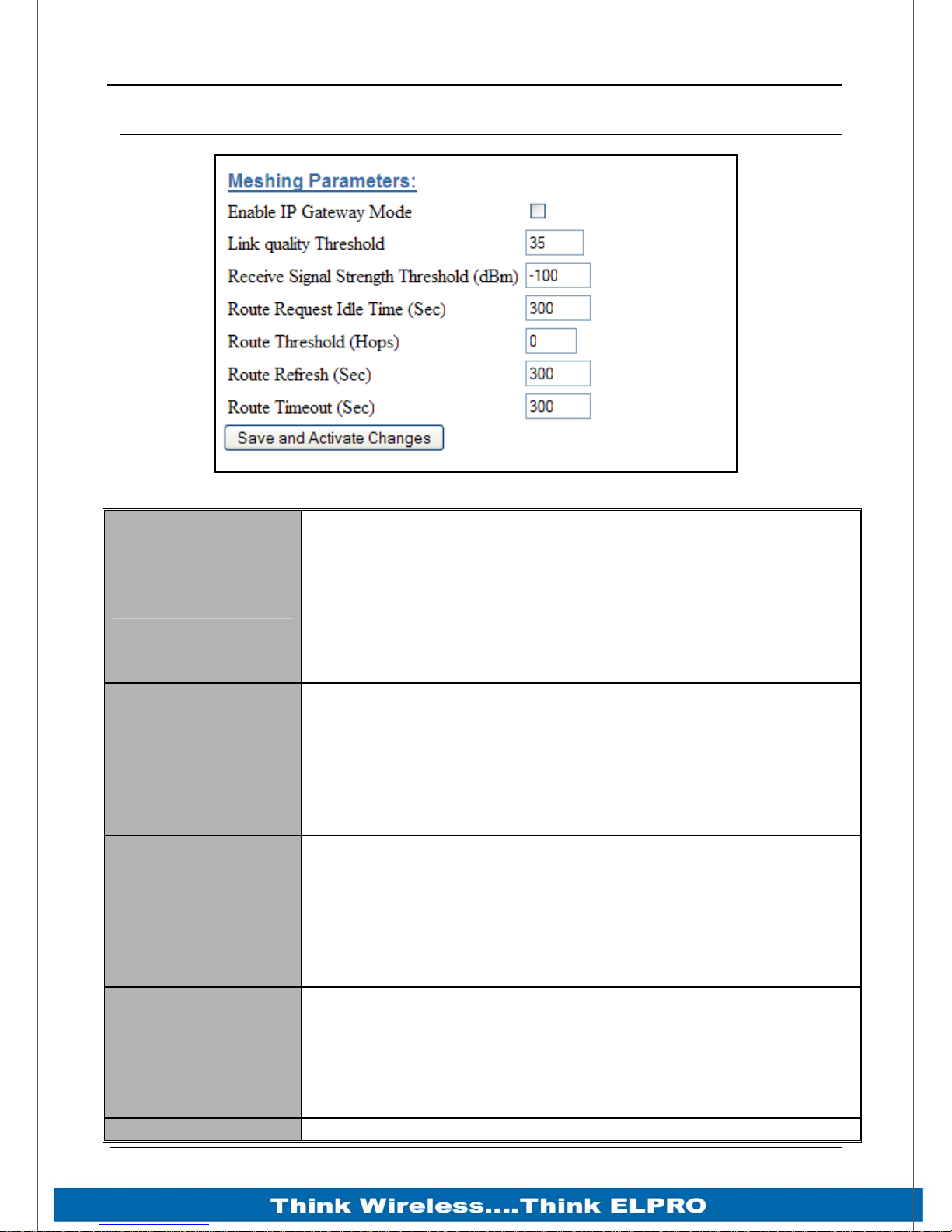
915U-2 Wireless I/O Page 77
Mesh
Figure 44 - Mesh Configuration
Enabling this option will advertise all other communicating
modules that an Ethernet Network is connected (IP address
range configured under Network Settings) and that all traffic for
Enable IP Gateway
Mode
Link Quality
Threshold
Receive Signal
Strength Threshold
Route Request Idle
Time (Sec)
Route Threshold Configures the number of additional hops that this unit reports
this network can be routed through this IP address. Care should
be taken when enabling this option as it can increase overall
network traffic. Default is off – Should remain off unless there is
an Ethernet network connected and other devices on the radio
network need to communicate to it.
The radio will use this threshold levels when establishing a mesh
link with other radios in the system. It represents a 0-100% level
of link quality (100 being the best). If the Link Quality is lower
than the threshold the link will be ignored.
Link Quality can be monitored on the Connectivity web page. If
the link quality is lower than this threshold, then mesh routes will
not be assigned over this link
The radio will use this threshold level when establishing a mesh
link with other radios in the system. When establishing a mesh
the radio sends out a broadcast message and then monitors the
signal strength from all other nodes that respond, if any of the
signal levels are below the “Receive Signal Strength Threshold”
the mesh link will be ignored. This threshold is used in
conjunction with the “Link Quality Threshold” above
Configures the time the unit will back off if a route request to
another unit fails. If the destination unit is switched off, and this
parameter is zero, the network may become congested with
route request messages, preventing other traffic from using the
radio network. Setting this parameter to higher values reduces
the network congestion.
Page 77 915U-2 Wireless I/O
Page 79
Page 78 915U-2 Wireless I/O
(Hops) when replying to mesh routing requests.
This parameter should be set to zero for units that should always
act as repeater units, and higher for units that are less preferred
as repeaters.
Setting this parameter to 10 means the unit will never be used
as a repeater.
Configures the period at which the unit will try to find a better
(shorter) route for an existing route. This is used where network
Route Refresh (Sec)
topology changes can occur that potentially allow a shorter path
to be taken. Without route refresh, the existing route would
continue to be used. Setting this parameter to zero disables
route refresh operation.
Configures the time the route will remain active for after the last
time it has been used. When this timeout expires, the route is
deleted from the unit and will have to be re-discovered the next
Route Timeout (Sec)
time communication with that destination unit is required.
Normally, this time should be greater than the WIBMesh update
time to a destination, so that the routes will not time out, and
remain active.
Save Changes and
Activate.
Save changes to non-volatile memory, and restarting the
function to load new configuration.
Page 78 915U-2 Wireless I/O
Page 80
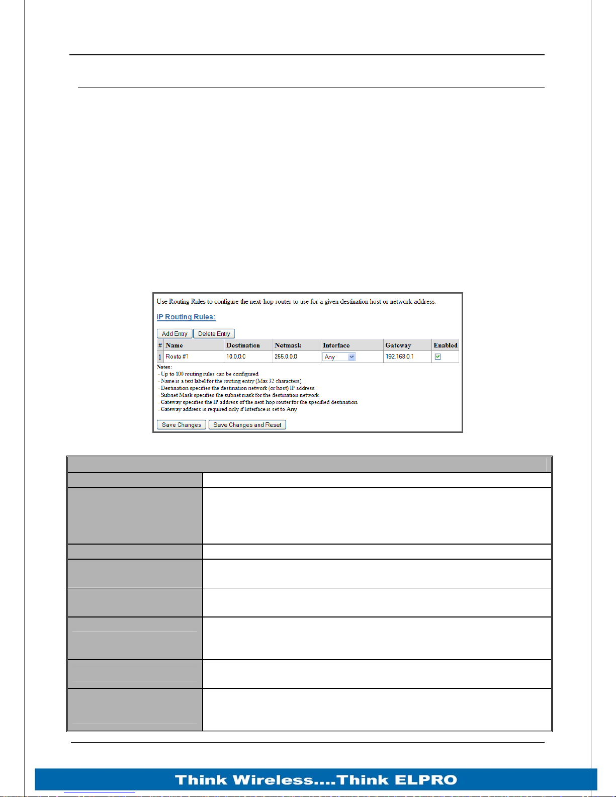
915U-2 Wireless I/O Page 79
IP Routing
When a 915U-2 receives an IP frame that is destined for an IP address on a different
network, it checks to see if the network address matches one of its own interfaces (i.e.
hard-wired Ethernet, or Radio) and forwards the frame appropriately. However, if the IP
network address does not match the network address of any of its interfaces, the 915U2 will forward the frame to its default gateway. In this case it is assumed that the default
gateway has a valid route to the destination.
In some cases, it is not practical to have just one default gateway (i.e. routed wireless
networks with more than two 915U-2 routers. If more than one “next-hop router” is
required, the 915U-2 allows for up to 100 routing rules to be configured. A routing rule
specifies a destination network (or host) IP address and the corresponding next-hop
router that messages for the specified destination will be forwarded to (Gateway). It is
assumed that the Gateway will then deliver the data to the required destination (or
forward it on to another router that will).
Figure 45 - IP Routing
IP Routing
Name A name to describe the routing rule (Max 32 characters).
The destination network or Host IP address. You can specify a
Destination
Netmask The subnet mask for the destination network.
Interface
Gateway
Enabled
Save Changes
Save Changes and
Reset.
whole network by entering the IP range 192.168.0.0 with a
Netmask of 255.255.255.0 or specify an individual host IP
address by setting the Netmask to 255.255.255.255.
Choose the interface to use for the route. Selections are
Radio, Ethernet or Any – Default is Any.
Specifies the IP address of the next-hop router for the
specified destination.
Check this box to enable the rule. You can Uncheck the box to
disable a routing rule without needing to re-enter the
information at a later time.
Save changes to non-volatile memory. The module will need
to be restarted before the changes take effect.
Save settings to non-volatile memory, and reboot 915U-2.
Once the module has completed the reboot sequence, all
changes are in effect.
Page 79 915U-2 Wireless I/O
Page 81
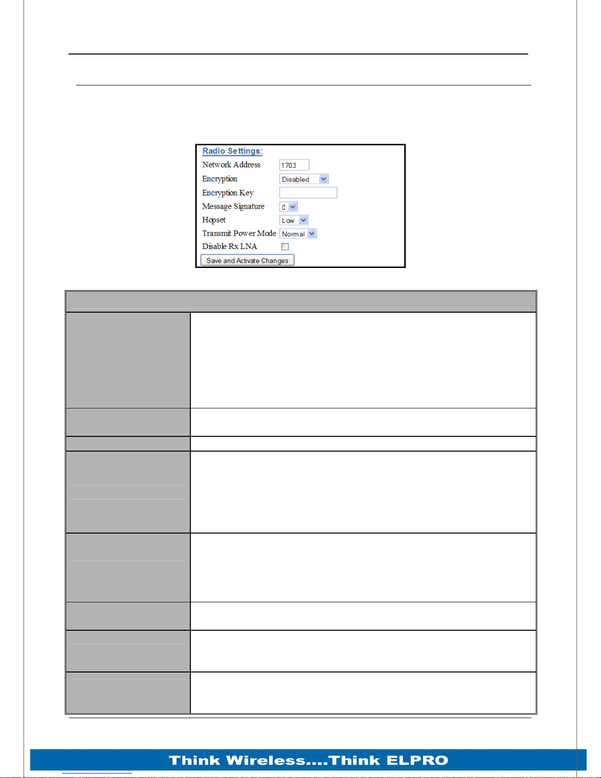
Page 80 915U-2 Wireless I/O
Radio Settings
Select the “Radio” Menu to change the following configuration parameters. If a change
is made, you need to select “Save Changes” to retain the changes. Changes will not
take effect until the unit is reset.
Figure 46 – Radio Configuration Screen
Radio Settings
A unique address that is used to differentiate one wireless
system from another, All radios that are required to
communicate within the system will need to have the same
Network Address
Encryption
Encryption Key Up to 32 characters are available for Encryption key.
Message Signature
Hopset
Transmit Power
Mode
Disable Rx LNA
Save Changes and
Reset.
Network Address
Messages received with a different System Address will be
ignored. It is used to prevent Cross-talk between systems.
Valid values are between 0 and 32768
Can select either 64 bit ELPRO Proprietary or 128 bit AES
encryption level from the drop down list
The radio preamble is a section of data at the head of a packet
that contains a unique “signature” that the radio locks on to
when receiving messages. Any message with a different
signature is ignored.
There are 4 different Message Signatures and all modules that
communicate together will need to have the same one set.
From here you can select from available Hopset bands, If the
radio has a Country code of US/Canada then there are 2 bands
available, Low (902-914MHz) and High (915-928MHz)
If country is Australia or New Zealand then the only option is
the high band
Change the Transmit power level from the Normal (1 W) to Low
Power (100 mW)
Check box to disable the LNA (Low Noise Amplifier)
Reduces the Receive Sensitivity by about 12dB, used during
Demos, Bench testing, etc.
Save settings to non-volatile memory, and reboot 915U-2.
Once the module has completed the reboot sequence, all
changes are in effect.
Page 80 915U-2 Wireless I/O
Page 82
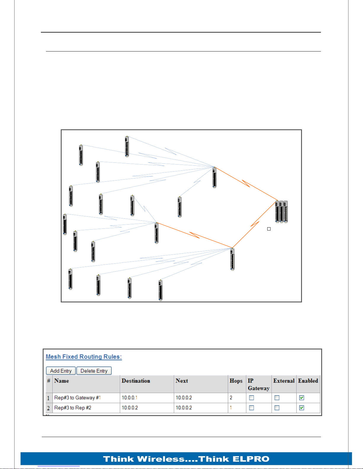
915U-2 Wireless I/O Page 81
Mesh Fixed Routes
In large radio systems there will often be a number of radios that will act as Repeaters
for the other radios. Because these sites are generally stationary they do not need to
learn the different paths and can have fixed routes back to the destination. We configure
these routes with Mesh Fixed Route Rules.
You can configure up to 100 fixed Route Rules for each site and the rules can be
targeted to a specific IP address by using a Host Route or a complete Subnet.
Example #1
PWR
RF
232
485
PWR
RF
232
485
ELPRO
915U-2
ELPRO
915U-2
PWR
RF
232
485
ELPRO
915U-2
PWR
RF
232
485
PWR
ELPRO
915U-2
RF
232
485
ELPRO
915U-2
PWR
RF
232
485
ELPRO
915U-2
PWR
RF
232
485
ELPRO
915U-2
PWR
RF
232
485
ELPRO
915U-2
PWR
RF
232
485
ELPRO
915U-2
PWR
RF
232
485
ELPRO
915U-2
Auto Paths - Moving
Vehicles, redundant paths,
Temporary paths, etc.
PWR
RF
232
485
ELPRO
915U-2
Fixed Repeater Site #3
Auto Paths - Moving
Vehicles, redundant paths,
Temporary paths, etc.
PWR
RF
232
485
ELPRO
915U-2
Mesh Fixed Routes 1
Fixed Repeater Site #1
Radio: 10.0.0.3
F
i
x
e
d
P
a
t
h
Subnet: 255.255.225.0
PWR
RF
232
485
ELPRO
915U-2
PWR
RF
232
485
ELPRO
915U-2
PWR
RF
232
485
ELPRO
915U-2
PWR
RF
232
485
ELPRO
915U-2
Fixed Repeater Site #2
PWR
RF
232
485
ELPRO
915U-2
Radio: 10.0.0.2
Subnet: 255.255.225.0
F
i
x
ed P
ath
Gateway #1
PWR
PWR
PWR
RF
OK
OK
232
TX
TX
485
RX
RX
h
t
a
P
d
e
x
i
F
ELPRO
ELPRO
ELPRO
915U-2
115S-XX
115S-XX
√
Enable IP Gateway Mode
Radio: 10.0.0.1
Subnet: 255.255.225.0
Ethernet: 192.168.1.1
Subnet: 255.255.255.0
Figure 47 - Mesh Fixed Route #1
The Network Diagram above shows a typical network with mesh fixed routes. Normally
a meshing network will automatically learn the routes within a network and setup
appropriate communication paths to the destination. When manually configuring these
routes all communication paths need to be setup by using Mesh Fixed Routing Rules.
Page 81 915U-2 Wireless I/O
Figure 48 - Mesh Fixed Route#2 Routing Rules
Page 83
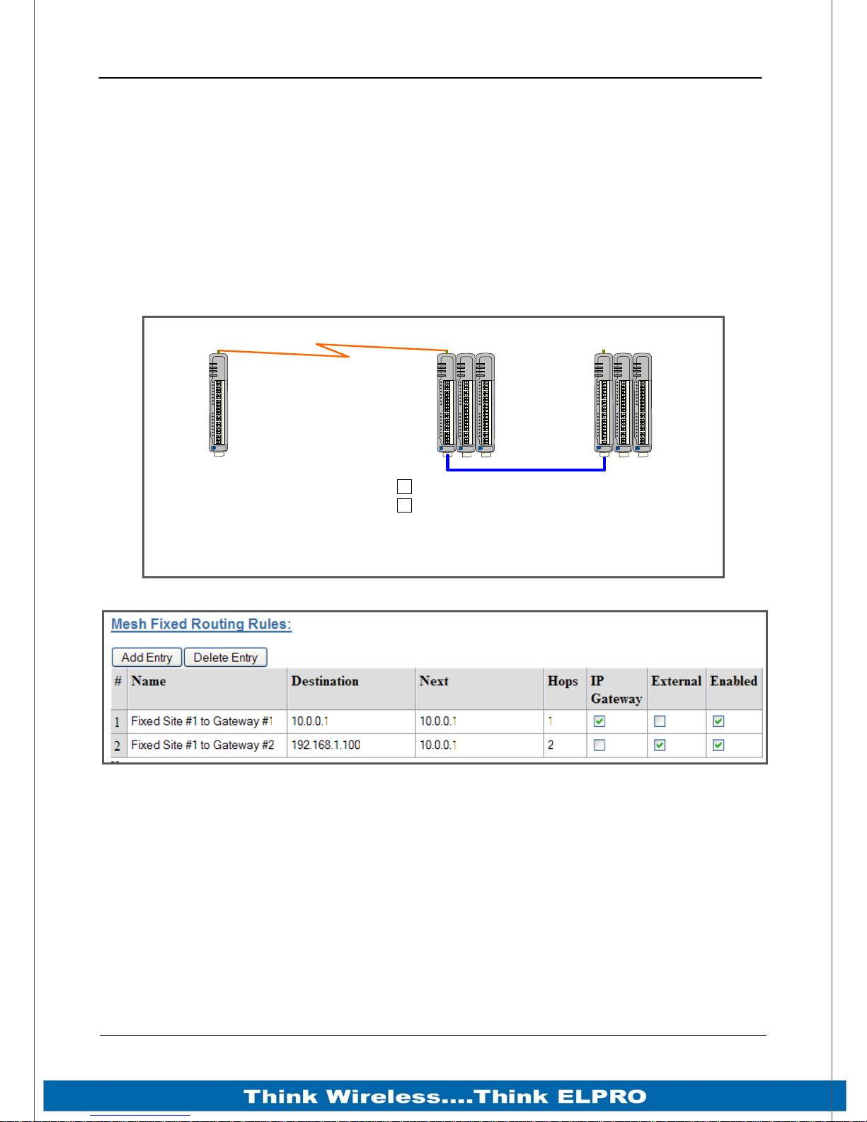
Page 82 915U-2 Wireless I/O
Figure 48 above show the Mesh Fixed Routing Rules for the network diagram in Figure
47 above.
In fixed Route #1 it shows the Destination IP Address will be 10.0.0.1 and its Next hop
will be 10.0.0.2, there will be a total of 2 hops and the ”IP Gateway” and “External” are
un ticked as the destination will be the local I/O on 10.0.0.1.
In Route #2 is a route showing the communication path with repeater #2. The
destination and next addresses are both 10.0.0.2 because it’s a single hop and again
the “IP Gateway” and “External” are un ticked as the communications is all local and not
through a Gateway or out of the mesh.
Example #2
Fixed Site #1
PWR
RF
232
485
ELPRO
915U-2
Radio: 10.0.0.2
Subnet: 255.255.225.0
Fixed Path
Gateway #1
PWR
RF
232
485
ELPRO
915U-2
√
Enable IP Gateway Mode
√
External
Radio: 10.0.0.1
Subnet: 255.255.225.0
Ethernet: 192.168.1.1
Subnet: 255.255.255.0
Figure 49 - Mesh Fixed Route #2
Gateway #2
PWR
PWR
PWR
PWR
OK
OK
TX
TX
RX
RX
ELPRO
ELPRO
115S-XX
115S-XX
PWR
RF
OK
OK
232
TX
TX
485
RX
RX
ELPRO
ELPRO
ELPRO
915U-2
115S-XX
115S-XX
Ethernet: 192.168.1.100
Subnet: 255.255.255.0
Figure 50 – Mesh Fixed Route #2 Routing Rules
Figure 50 shows the routing rules for the network diagram Figure 49- Mesh Fixed Route
#2” above
The first route shows the destination and next addresses are both 10.0.0.1 as it’s a
single hop. Because the destination is a Gateway on an external network the IP
Gateway must be enabled.
The second routing rules shows the Destination (192.168.1.100) is an external network
and is outside of the radio mesh, therefore the External tick box must be enabled. The
next address will be 10.0.0.1, which is the IP Gateway.
Page 82 915U-2 Wireless I/O
Page 84
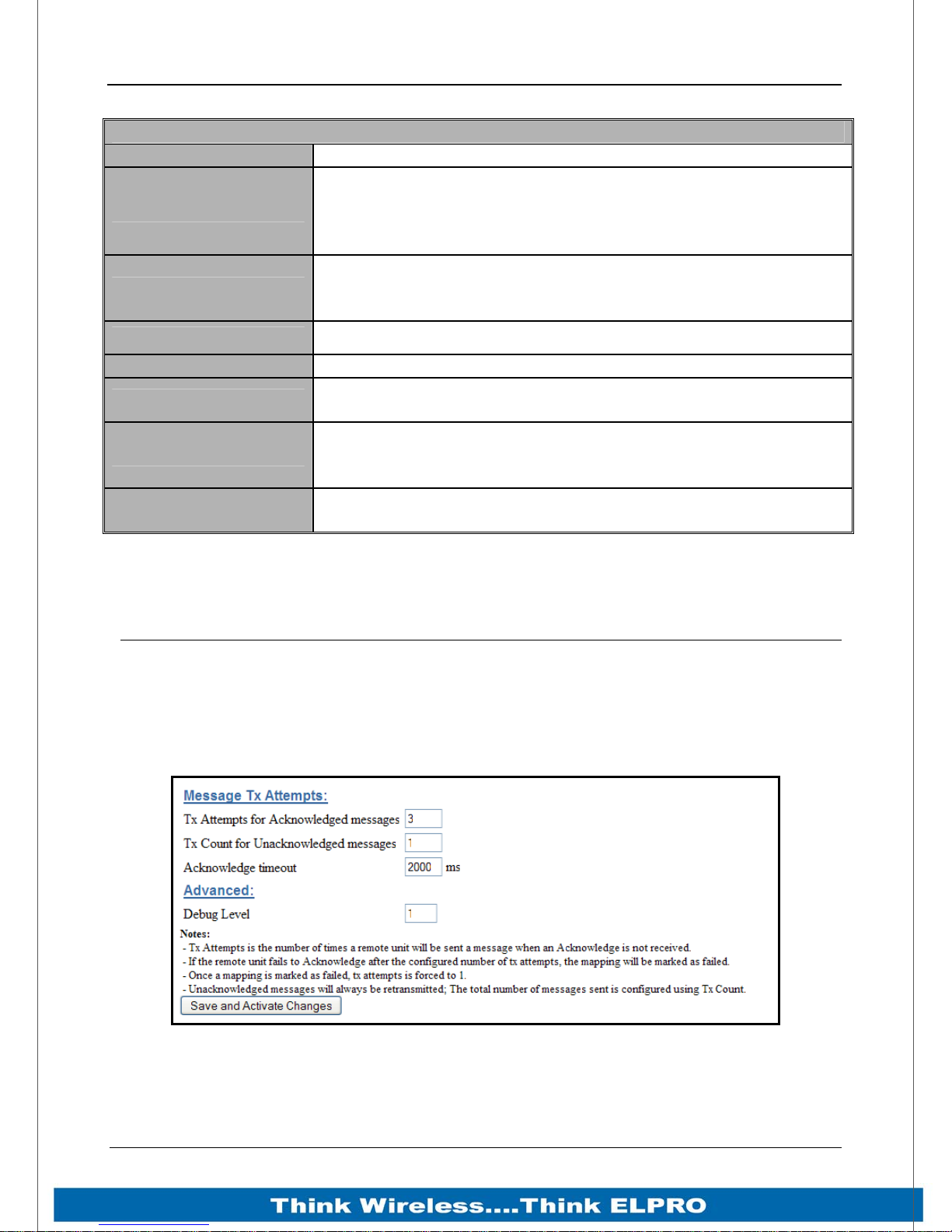
915U-2 Wireless I/O Page 83
IP Routing
Name A name that describes the routing rule (Max 32 characters).
The destination network or Host IP address. You can specify a
Destination
Next
Hops Indicates the number of routing hops to the destination.
IP Gateway Indicates the Destination acts as a gateway out of the mesh
External
Enabled
Save Changes and
Activate.
whole network by entering the IP range 192.168.0.0 with a
Netmask of 255.255.255.0 or specify an individual host IP
address.
Specifies the IP address of the next hop router for the
specified destination. Next is the same as destination for the
final hop. Next is the same as destination for one-hop routes.
Indicates that it is routed through a Gateway out side of the
mesh
Check this box to enable the rule. You can Uncheck the box to
disable a routing rule without needing to re-enter the
information at a later time.
Save changes to non-volatile memory, and restarting the
function to load new configuration.
WIBMesh Configuration
WIBMesh is an extremely efficient proprietary radio protocol used for radio
communications. The protocol is based on the “Ad hoc On Demand Distance Vector”
(AODV) routing algorithm which is a routing protocol designed for ad hoc networks.
There is very little configuration for the WIBMesh as the protocol automatically routes
through the mesh to the destination.
Page 83 915U-2 Wireless I/O
Figure 51 – WIBMesh Configuration Screen
Page 85
Page 84 915U-2 Wireless I/O
WIBMesh Configuration
How many times the configured module will attempt to communicate
a message to another module (message reties).
After failing to communicate the module will be flagged as being in
TX Attempts for
Acknowledged
messages
comms fail.
If it tries to communicate to the remote module again, it will reduce
the number of attempts down to one as it has been flagged as being
in Comms fail.
If communications is restored the module will go back to transmitting
the number of time configured in “Tx Attempts for Acknowledged
messages”.
The number of times it transmits the same data message. It is used if
the 915U-2 has been setup as a transmit only module (similar to the
TX count for
unacknowledged
messages
older ELPRO 905U-K or 505U-K modules). It is done by not
selecting the “Ack” tick box in any Block Write and Gather/Scatter
Block mappings. (See 0 “WIBMesh Mappings” below)
Being a Transmit only module there is no communication handshake
between modules so transmitting the same message a number of
times gives a greater reliability in communications.
Acknowledge
timeout
Time to wait for the Acknowledgement before the message is timed
out. The default time is 2 Seconds but the time can be increased to
10 seconds for very long Mesh networks
The level of debug information that can be shown via the serial port
Debug Level
during normal operation and boot up. A value between 1 (only show
normal operating parameters) and 8 (showing all debug messages)
Save Changes
and Reset.
Save settings to non-volatile memory, and reboot 915U-2. Once the
module has completed the reboot sequence, all changes are in
effect.
Page 84 915U-2 Wireless I/O
Page 86
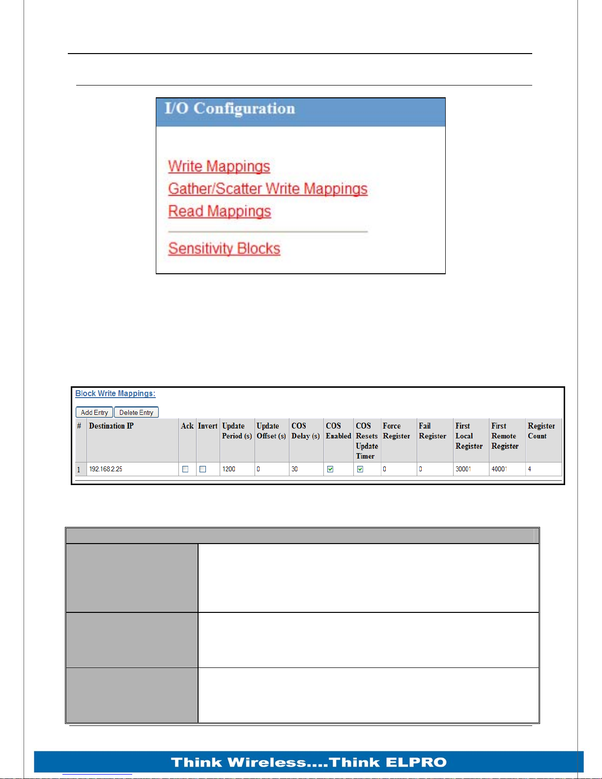
915U-2 Wireless I/O Page 85
WIBMesh Mappings
Figure 52 – WIBMesh Mappings
Selecting WIBMesh Mappings from the right hand side of the main menu will show the
I/O Configuration screen.
This is where you configure Read, Write and Gather/Scatter mappings as well as any
Sensitivity Blocks.
Write Mappings (Writing Local I/O to remote I/O)
Figure 53 – Write Mappings
Add or delete mapping by using the buttons then select “Save and Activate Changes”.
Block Write Mapping
This is the IP address that you wish to write the I/O to. If
mapping 915U-2 I/O to another 915U-2 I/O via radio, the
Destination IP
Ack
Invert
destination IP address must be the radio IP address. If
mapping via ethernet port (or WAN) then the destination IP
Address will be the Ethernet IP of the destination.
Selecting this box means the mapping will be acknowledged
when the end device receives the message. This is an end-toend acknowledgement, and is over and above the normal
hop-by-hop frame acknowledgment between links.
This will allow the mapping to be inverted. E.g. if the digital
input is on and inverted then the output will be off and visa
versa. Applies to all of the I/O in the mapping and can only be
used with Words and Bits, No Floating Point or Long values
Page 85 915U-2 Wireless I/O
Page 87
Page 86 915U-2 Wireless I/O
can be inverted.
Update Period (sec)
This is the period that the mappings are sent as an update or
check signal. (Zero disabled updates)
Configures an offset time for the update mapping. Used to
stagger the update transmissions so on start-up and every
Update Offset (sec)
update period the module does not send all mapping at the
same time. Default will be 0 however the normal would be
around 5 seconds.
You can enter a delay period such that the message is
Change of State
(COS) Delay (sec)
delayed from sending for the configured time. Used to hold off
the transmissions to allow more COS messages to be added
to the mapping.
Can enable or disable the COS messages. If enabled the
Change of State
(COS) Enabled
values will be sent on COS and if the value complies with any
Sensitivity blocks (see Sections 0“Sensitivity Block”). If COS is
disabled, messages would only be sent on the update period.
The Update Period Timer will be reset if this option is enabled
and a COS is received in between updates, meaning it will not
receive another update until a further Update period has
COS Resets Update
Timer
elapsed - Can help reduce the amount of radio traffic
produced when multiple mappings are configured.
Note: If the Turn on an I/P and at <30s past COS, check COS
is sent 30s past change and old COS time is not used
Turn on an I/P and at >30s past COS, check COS is only sent
at the old COS time and not at 30s past the change or both.
Register location that when written to will force the Write
Force Reg
Mapping to be sent. E.g. External device can initiate the
transmissions. (reg 501 – 3000)
Register location that indicates a failure to communicate with
Fail Reg
the configured remote Destination Address. Note: Register
must be Bit register, i.e. Digital I/O or internal Bit registers
(10501, 501, etc) also ‘Ack’ must be enabled.
First Local Reg Starting Local address that values will be written to.
First Remote Reg Starting Remote address that the values will read from.
Reg Count Total number of register values (consecutive)
Save Changes and
Activate.
Save changes to non-volatile memory, and restarting the
function to load new configuration.
Page 86 915U-2 Wireless I/O
Page 88
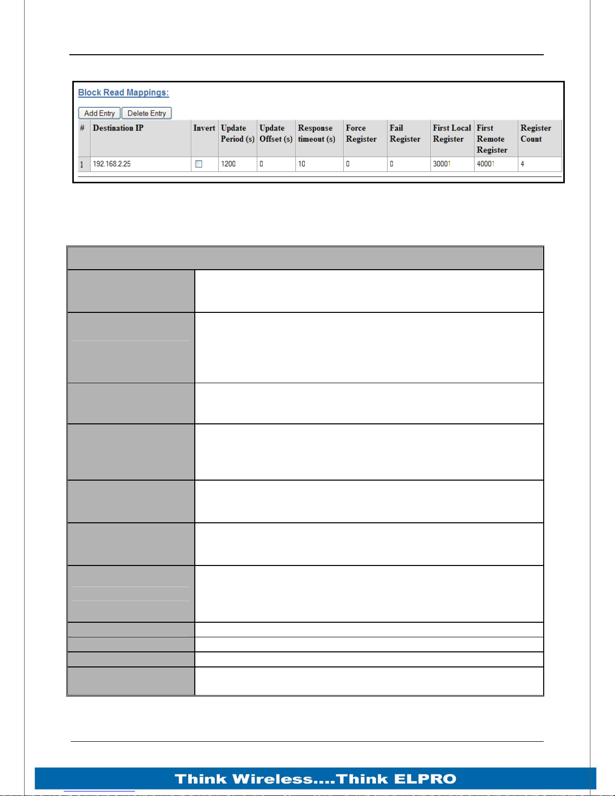
915U-2 Wireless I/O Page 87
Read Mappings (Read remote I/O and storing it locally)
Figure 54 – Read Mappings
Add or delete mapping by using the buttons then select “Save and Activate Changes”.
Block Read Mapping
This is the IP address that you wish to read the I/O from. If
Destination IP
Invert
reading I/O via radio from another 915U-2 the destination IP
address must be the radio IP address.
This will allow the mapping to be inverted. E.g. if the digital
input is on and inverted then the output will be off and visa
versa. Applies to all the I/O in the mapping and can only be
used with Words and Bits, No Floating Point or Long values
can be inverted
Update Period (sec)
This is the period that the mappings are sent as an update or
check signal. (Zero disables the update)
Allows an offset to be configured for each mapping. Used to
Update Offset
(sec)
stagger the transmissions so on start-up the module does not
try to read all mapping at the same time. Default will be 0
however the normal would be around 5 seconds.
The time the module needs to count down before registering a
Response Timeout
communications failure for the configured read mapping.
When the time out is complete, the FailReg will be activated.
Register location that when written to will force the Read
Force Reg
Mapping to be sent. E.g. External device can initiate the
transmissions.
Register location that will indicate a failure to communicate
Fail Reg
with the remote Destination Address. Note: Register must be
Bit register, i.e. Digital I/O or internal Bit registers (10501, 501,
etc) also 'Ack' must be enabled.
First Local Reg Starting Local address that values will be written to.
First Remote Reg Starting Remote address that the values will read from.
Reg Count Total number of register values (consecutive)
Save Changes and
Activate.
Save changes to non-volatile memory, and restarting the
function to load new configuration.
Page 87 915U-2 Wireless I/O
Page 89
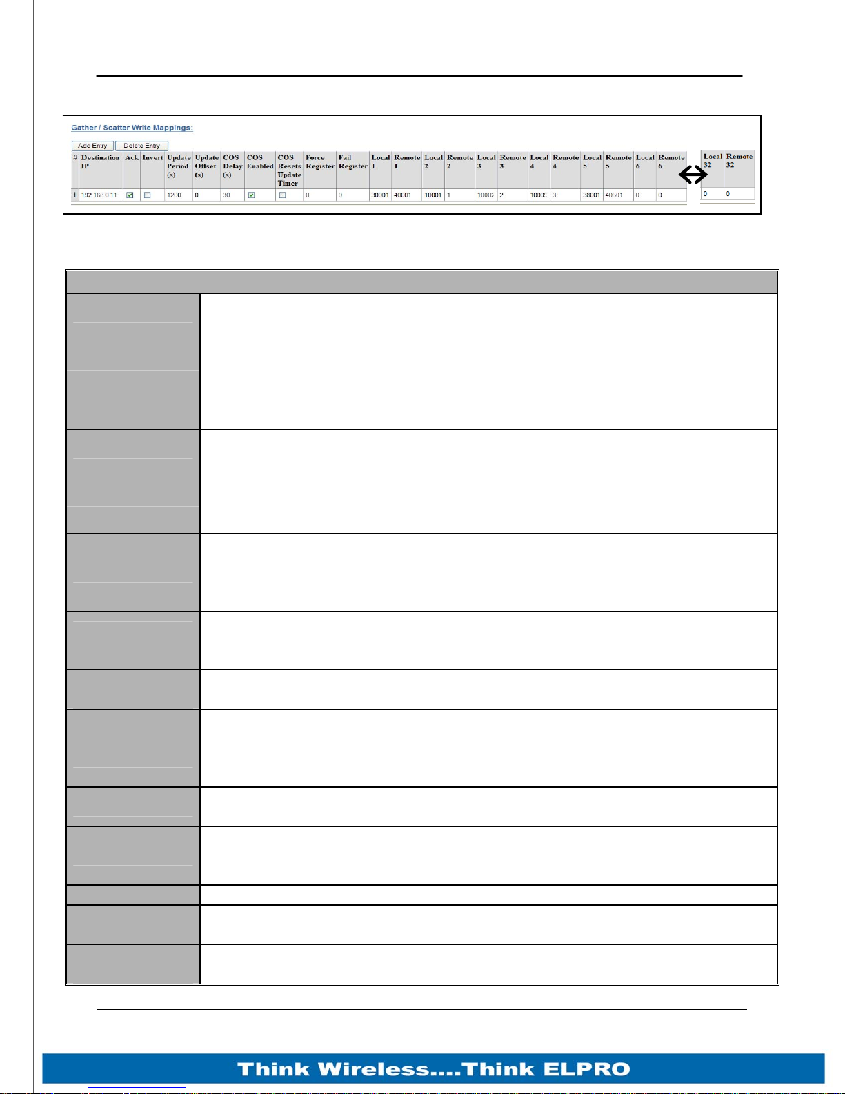
Page 88 915U-2 Wireless I/O
Gather/Scatter Write Mappings
Figure 55 – Gather/Scatter Mappings
Gather/Scatter Write Mapping
This is the IP address that you wish to write the I/O to. If mapping 915U-2
Destination IP
Ack
Invert
I/O to another 915U-2 I/O via radio, the destination IP address must be the
radio IP address. Use the Ethernet IP of the destination if mapping via
ethernet port (or WAN).
Selecting this box will mean the mapping will be acknowledged when the
end device gets the mapping. This is over and above the normal Ethernet
frame acknowledgments between links.
This will allow the mapping to be inverted. E.g. if the digital input is on and
inverted then the output will be off and visa versa. Applies to all the I/O in
the mapping and can only be used with Words and Bits, No Floating Point
or Long values
Update Period This is the period that the mappings are sent as an update or check signal.
Allows an offset to be configured for each mapping. Used to stagger the
Update Offset
transmissions so on start-up the module does not try to send all mapping at
the same time. Default will be 0 however the normal would be around 5
seconds.
Change of State
(COS) Delay
Change of State
(COS) Enabled
You can enter a delay period such that the message is delayed from
sending for the configured time. Used to hold off the transmissions to allow
more COS messages to be added to the mapping.
Can enable or disable the COS messaged. If disabled messages would
only be sent on the update period.
Enabling this timer will mean If a COS is received in between any updates it
COS Resets
Update Timer
will reset the Update timer, meaning it will not receive another update until
the further Update period has passed.- used to reduce the amount of radio
traffic
Force Reg
Register location that when written to will force the Write Mapping to be
sent. E.g. External device can initiate the transmissions.
Register location that indicates a failure to communicate with the configured
Fail Reg
remote Destination Address. Note: Register must be Bit register, i.e. Digital
I/O or internal Bit registers (10501, 501, etc) also ‘Ack’ must be enabled.
Reg Count Total number of register values (consecutive)
L1 & R2 – L32
& R32
Save Changes
and Activate.
Local and Remote pairs. Up to 32 scattered local I/O registers can be
mapped to 32 scattered remote I/O registers
Save changes to non-volatile memory, and restarting the function to load
new configuration.
Page 88 915U-2 Wireless I/O
Page 90
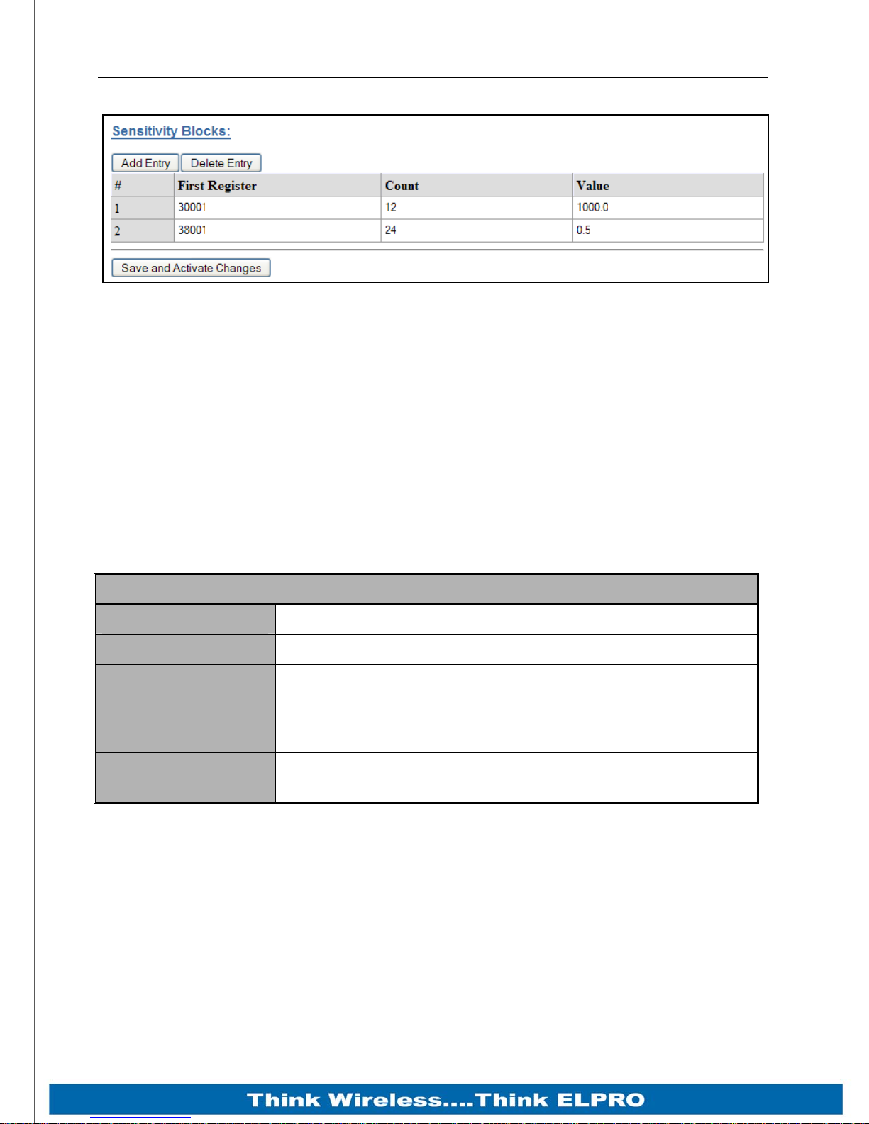
915U-2 Wireless I/O Page 89
Sensitivity Block
Figure 56 – Sensitivity Block
All registers have a configurable “Sensitivity” value, which determines how much the
register needs to change by before being sent as a “Change of State” (COS).
All registers have a default sensitivity value of 1 except the following.
The 12 analog inputs have a sensitivity of 1000 (3.2%) and the 24 floating point values
will have a default sensitivity of 0.5 units. In the case of 38001 – 38004 this will be
0.5mA, in the case of 38005-38012 it will be Volts and in 38013 – 38016 it will be Hertz.
(The reason is so the module does not send every single bit change of an analog value
and subsequently saturate the radio channel with unwanted change messages.
If a lower sensitivity is required then the above blocks can be adjusted and up to 48
more Sensitivity Blocks can be configured for different registers or different values.
They are configured as per the table below
Sensitivity Blocks
First Register
Count
This is the starting register
Indicates the number of registers in the sensitivity block
This is the number of counts the value needs to change by to
Value
force a COS, e.g. a value of 1000 would be a change of 1000
counts in the total range (32768), which would represent
about 3%
Save Changes and
Activate.
Save changes to non-volatile memory, and restarting the
function to load new configuration.
Page 89 915U-2 Wireless I/O
Page 91
Page 90 915U-2 Wireless I/O
915U-2 Module I/O Registers
I/O Description Input Output
Digital I/O 1
Digital I/O 2
Digital I/O 3
Digital I/O 4
Digital I/O 5
Digital I/O 6
Digital I/O 7
Digital I/O 8
Analog Input 1
Analog Input 2
Analog Input 3
Analog Input 4
Analog Input 5
Analog Input 6
Analog Input 7
Analog Input 8
Analog Input 9
Analog Input 10
Analog Input 11
Analog Input 12
Analog Input 13
Analog Input 14
Analog Input 15
Analog Input 16
Analog Setpoint 1
Analog Setpoint 2
Analog Setpoint 3
Analog Setpoint 4
Analog Setpoint 5
Analog Setpoint 6
Analog Setpoint 7
Analog Setpoint 8
Analog Setpoint 9
Analog Setpoint 10
Analog Setpoint 11
Analog Setpoint 12
Analog Output 1
Analog Output 2
Pulsed Input 1 Count
Digital Input/Output 1 10001 1
Digital Input/Output 2 10002 2
Digital Input/Output 3 10003 3
Digital Input/Output 4 10004 4
Digital Input/Output 5 10005 5
Digital Input/Output 6 10006 6
Digital Input/Output 7 10007 7
Digital Input/Output 8 10008 8
Analog input 1 mA 30001
Analog input 2 mA 30002
Analog input 3 mA 30003
Analog input 4 mA 30004
Local Supply Voltage 30005
Local Battery Voltage 30006
Local +24V Loop Supply 30007
Local 115S Supply Voltage 30008
Analog Input 1 Volts 30009
Analog Input 2 Volts 30010
Analog Input 3 Volts 30011
Analog Input 4 Volts 30012
Pulsed Input Rate 1 30013
Pulsed Input Rate 2 30014
Pulsed Input Rate 3 30015
Pulsed Input Rate 4 30016
Analog Setpoint 1 10009
Analog Setpoint 2 10010
Analog Setpoint 3 10011
Analog Setpoint 4 10012
Analog Setpoint 5 10013
Analog Setpoint 6 10014
Analog Setpoint 7 10015
Analog Setpoint 8 10016
Analog Setpoint 9 10017
Analog Setpoint 10 10018
Analog Setpoint 11 10019
Analog Setpoint 12 10020
Analog Output 1 40001
Analog Output 2 40002
Pulsed Input Count 1 36001-36002
Page 90 915U-2 Wireless I/O
Page 92
915U-2 Wireless I/O Page 91
Pulsed Input 2 Count
Pulsed Input 3 Count
Pulsed Input 4 Count
Pulsed Input 1 Rate
Pulsed Input 2 Rate
Pulsed Input 3 Rate
Pulsed Input 4 Rate
Pulsed Output 1 Count
Pulsed Output 2 Count
Pulsed Output 3 Count
Pulsed Output 4 Count
Analog I/P Floating Point
Analog I/P Floating Point
Analog I/P Floating Point
Analog I/P Floating Point
Analog I/P Floating Point
Analog I/P Floating Point
Analog I/P Floating Point
Analog I/P Floating Point
Analog I/P Floating Point
Analog I/P Floating Point
Analog I/P Floating Point
Analog I/P Floating Point
Analog I/P Floating Point
Analog I/P Floating Point
Analog I/P Floating Point
Analog I/P Floating Point
Analog I/P Floating Point
Analog I/P Floating Point
Analog I/P Floating Point
Analog I/P Floating Point
Pulsed Input Count 2 36003-36004
Pulsed Input Count 3 36005-36006
Pulsed Input Count 4 36007-36008
Pulsed Input Rate 1 30013
Pulsed Input Rate 2 30014
Pulsed Input Rate 3 30015
Pulsed Input Rate 4 30016
Pulsed Output Count 1 46001-46002
Pulsed Output Count 2 46003-46004
Pulsed Output Count 3 46005-46006
Pulsed Output Count 4 46007-46008
(FP) Analog input 1 38001-38002
(FP) Analog input 2 38003-38004
(FP) Analog input 3 38005-38006
(FP) Analog input 4 38007-38008
(FP) Analog input 5 38009-38010
(FP) Analog input 6 38011-38012
(FP) Analog input 7 38013-38014
(FP) Analog input 8 38015-38016
(FP) Analog input 9 38017-38018
(FP) Analog input 10 38019-38020
(FP) Analog input 11 38021-38022
(FP) Analog input 12 38023-38024
(FP) Analog input 13 38025-38026
(FP) Analog input 14 38027-38028
(FP) Analog input 15 38029-38030
(FP) Analog input 16 38031-38032
(FP) Analog Output 1 48001
(FP) Analog Output 2 48002
(FP) Analog Output 3 48003
(FP) Analog Output 4 48004
115S Serial Expansion Modules I/O Registers
Description
Digital I/O 1
Digital I/O 2
Digital I/O 3
Digital I/O 4
Digital I/O 5
Digital I/O 6
Page 91 915U-2 Wireless I/O
Inputs Outputs Inputs Outputs Inputs Outputs
10001 1 10001 1 10001 1
10002 2 10002 2 10002 2
10003 3 10003 3 10003 3
10004 4 10004 4 10004 4
10005 5 10005 5 10005 5
10006 6 10006 6 10006 6
115S-11 115S-12 115S-13
Page 93
Page 92 915U-2 Wireless I/O
Digital I/O 7
Digital I/O 8
Digital I/O 9
Digital I/O 10
Digital I/O 11
Digital I/O 12
Digital I/O 13
Digital I/O 14
Digital I/O 15
Digital I/O 16
Analog I/O 1
Analog I/O 2
Analog I/O 3
Analog I/O 4
Analog I/O 5
Analog I/O 6
Analog I/O 7
Analog I/O 8
Pulsed I/O Count 1
Pulsed I/O Count 2
Pulsed I/O Count 3
Pulsed I/O Count 4
Pulsed I/O Count 5
Pulsed I/O Count 6
Pulsed I/O Count 7
Pulsed I/O Count 8
Pulsed I/O Rate 1
Pulsed I/O Rate 2
Pulsed I/O Rate 3
Pulsed I/O Rate 4
Supply Voltage
Analog Loop Supply
10007 7 10007 7 10007 7
10008 8 10008 8 10008 8
10009 9
10010 10
10011 11
10012 12
10013 13
10014 14
10015 15
10016 16
30001 40001
30002 40002
30003 40003
30004 40004
30005 40005
30006 40006
30007 40007
30008 40008
30017-30018 30009 30009 30009
30019-30020 30010 30010 30010
30020-30022 30011 30011 30011
30023-30024 30012 30012 30012
30013 30013 30013
30014 30014 30014
30015 30015 30015
30016 30016 30016
30001
30002
30003
30004
30033 30033 30033
30034 30034 30034
All Expansion I/O is calculated by adding the module address multiplied by 20 to the I/O
address in the table.
E.g
Digital input #1 on an 115S-11 (address 5) would be: (5x20) + 10001 = 100 + 10001 = 10100
Digital output #2 on an 115S-11 (address 6) would be: (6x20) + 2 = 120 + 2= 121
Analog input #3 on an 115S-12 (address 3) would be: (3x20) + 30003 = 60 + 30003 = 30063.
Analog Output #8 on an 115S-13 (address 7) would be: (7x20) + 40007 = 140 + 40007 =
40146
Page 92 915U-2 Wireless I/O
Page 94
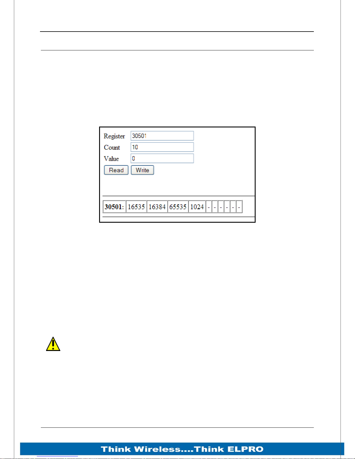
915U-2 Wireless I/O Page 93
Fail Safe Configuration
Fail Safe Block configuration allows registers to be set to a pre configured value on
startup as well as configuring the outputs to reset to a predefined value after a timeout
period has elapsed, when the real value comes in it will update as normal. Also if the
value is lost because of a communication problem it can be configured to set the output
to a failsafe value after the pre-configured time.
“Invalid” register state
Figure 57- Invalid Register State
All registers within the module can have various states depending on what type of
register it is and what sort of value it holds, an analog would be between 0 and the
maximum 65535, a digital can be 0 or 1, etc.
All registers that are not associated with any physical I/O have another state which we
call “invalid”, this state means that the value has not been written to and so does not
hold a value but more a non value or null.
If you were to read the registers using the “I/O Diagnostics” an invalid register would
read “~“as shown in Figure 57 above.
Any mapping with an invalid register will be inhibited from sending. This is to
ensure the data that gets to the destination is valid and not just default values
that the module starts up with. Refer to section 0“Fail Safe Blocks” below for a
way of giving registers a valid value at start-up
Page 93 915U-2 Wireless I/O
Page 95
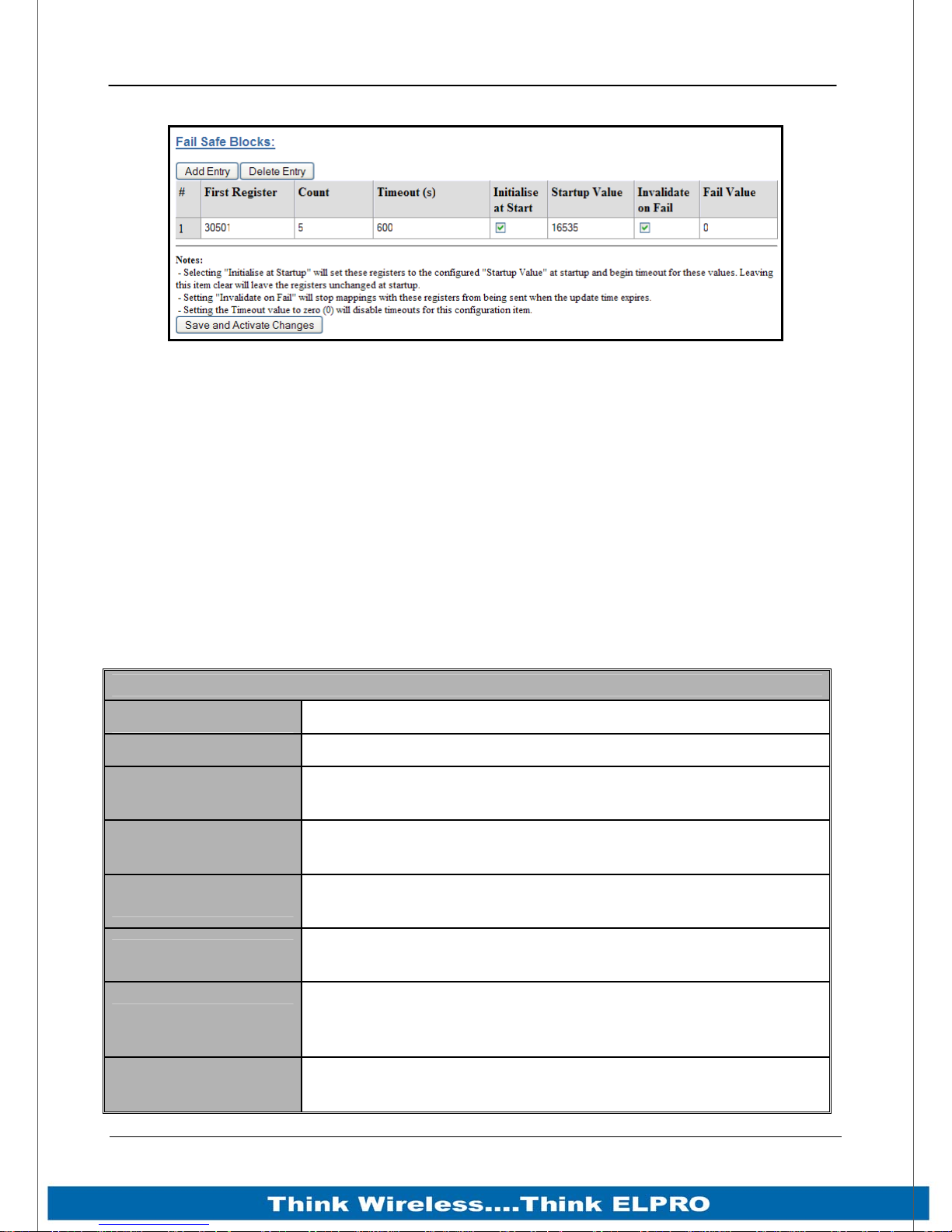
Page 94 915U-2 Wireless I/O
Fail Safe Blocks
Figure 58 – Fail Safe Blocks
In the screen shot above, register 30501 is an analog value that has been mapped from
another module, it has an update interval of 1 minute.
On startup this module will write a value of 16535 into register 30501 and then start
counting down from the “Timeout” value (in this case 600 seconds).
If after 600 seconds, the module still has not received an update from the other module,
register 30501 will be set to the “Fail Value” (in this case 0).
If the “Invalidate on Fail” were ticked, the value would be set to a null or invalidated
value (-).
If this register was mapped to some other location the mapping would be inhibited until
the” Invalid” value was updated with a real value.
The maximum number of Fail Safe blocks you can have is 50.
Fail Safe Blocks
First Register
Count
Timeout
Initialise at Startup
Startup Value
Invalidate on Fail
This is the starting register
Indicates the number of registers in the Fail Safe block
This is the starting timeout value in seconds. (setting value to
0 will disable the Timeouts)
Indicates that on startup the Fail Safe Block registers will be
set to the Startup value.
This is the value that the Fail Safe block registers will be set
to on Startup if the “Initialise at Startup” is ticked.
If ticked will set the registers back to an Invalid state (See
above) when failed.
The value the register will be set to if “Invalidate on Fail” is
Fail Value
ticked and the timeout is reached, otherwise this value is
ignored.
Save Changes and
Activate.
Save changes to non-volatile memory, and restarting the
function to load new configuration.
Page 94 915U-2 Wireless I/O
Page 96
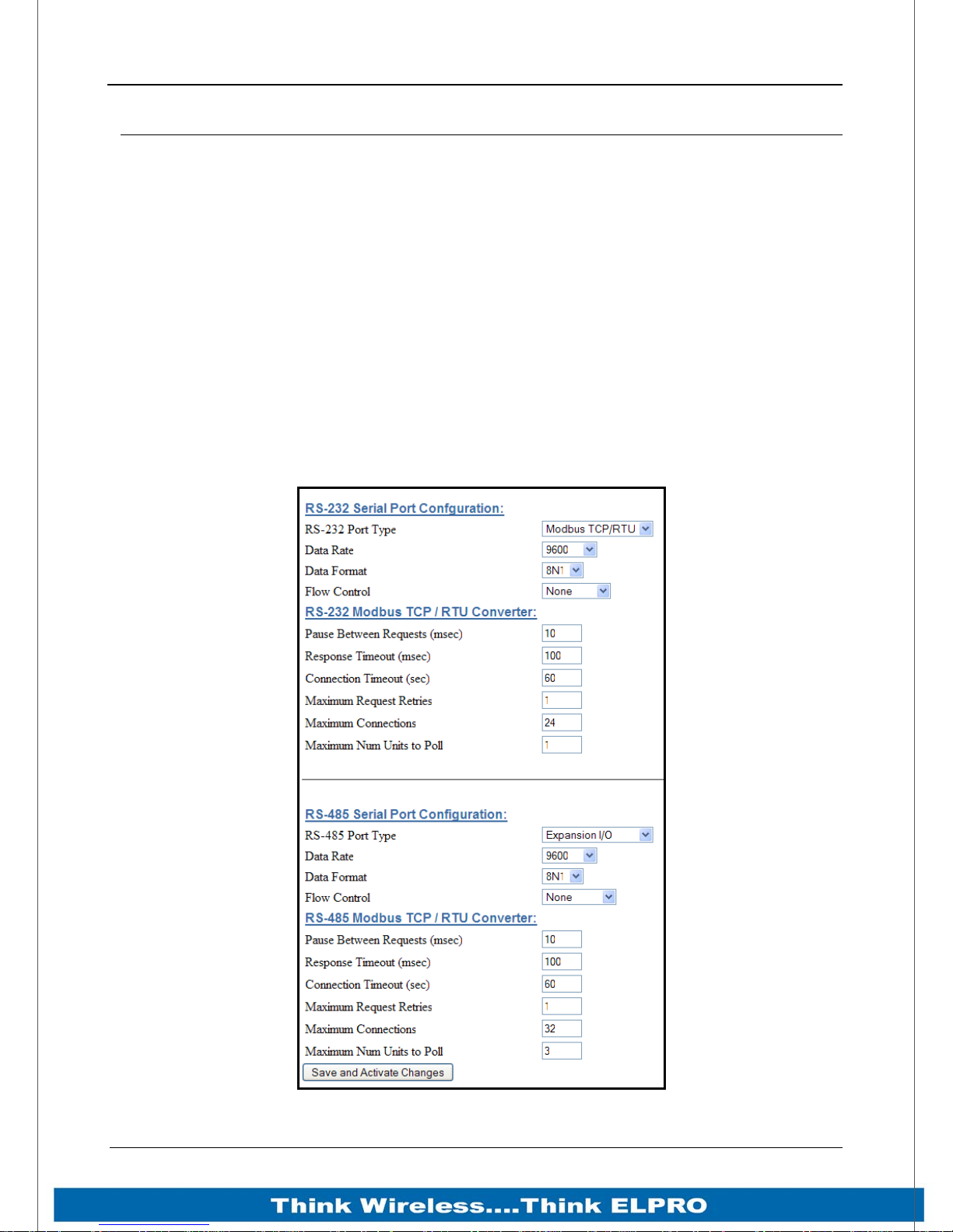
915U-2 Wireless I/O Page 95
Serial Configuration
The 915U-2 has an RS-232, and an RS-485 port for serial communications. These ports
may be used to connect external Modbus RTU devices via the Modbus TCP to RTU
Gateway and or ELPRO serial expansion I/O modules.
Modbus TCP to RTU Gateway
The Modbus TCP to RTU Gateway allows an Ethernet Modbus/TCP Client (Master) to
communicate with a serial Modbus RTU Slave. The 915U-2 makes this possible by
internally performing the necessary protocol conversion. The conversion is always
performed by the 915U-2, which is directly connected to the Modbus serial device (i.e.
only this module needs to have Modbus TCP to RTU Gateway enabled).
The example below demonstrates how a Modbus/TCP Client (Master) can connect to
one or more Modbus RTU (i.e. serial) Slaves. In this example the remote 915U-2 is
configured with the “RS232 Modbus/TCP to RTU Gateway” enabled
.
Page 95 915U-2 Wireless I/O
Figure 59– Serial Port Configuration
Page 97
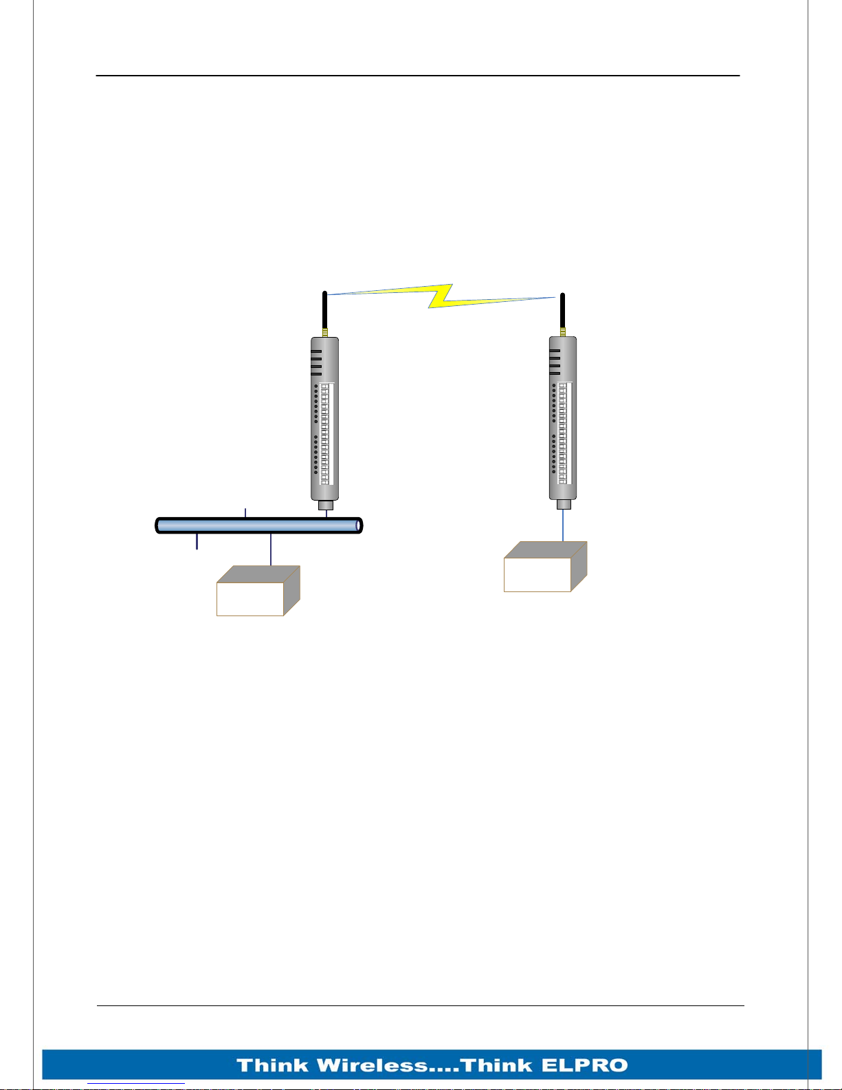
Page 96 915U-2 Wireless I/O
Once enabled, the gateway converts the Modbus/TCP queries received from the Master
into Modbus RTU queries and forwards these over the RS232 port to the Slave.
When the serial response to the query arrives from the Slave, it is converted to a
Modbus/TCP response and forwarded via the network to the Modbus/TCP Master. If no
response was received serially by the 915U-2 within the configured Response Timeout,
the 915U-2 will initiate a number of retries specified by the configured Maximum
Request Retries.
The Modbus TCP to RTU Gateway may be configured to operate on either the RS-232
or RS-485 port.
LAN
Modbus TCP
Client (Mas te r)
Local
915U-2
Remote
915U-2
PWR
RF
232
485
D1 D2 D3 D4 D5 D6 D7 D8
PWR
RF
232
485
D1 D2 D3 D4 D5 D6 D7 D8
RS232
Modbus TCP
COM+24V + - + - COM+24V
AI 1 AI2
AI3 AI4
AO1 AO2
++
E2
COM+24V + - + - COM+24V
AI 1 AI2
AI3 AI4
AO1 AO2
++
E2
to RTU
Gateway
RS232
Modbus RTU
Slave
Page 96 915U-2 Wireless I/O
Figure 60 – Modbus TCP to RTU
Page 98
915U-2 Wireless I/O Page 97
RS232 / RS485 Modbus TCP / RTU Converter
Pauses Between
Requests
Response Timeout
Connection Timeout
Maximum Request
Retries
Maximum
Connections
Maximum num units
to Poll
Save Changes and
Activate.
Enter the delay between serial request retries in milliseconds
Enter the serial response timeout in milliseconds – a serial
retry will be sent if a response is not received within this
timeout.
Enter the TCP connection timeout in seconds – if no
Modbus/TCP data is received within this timeout then the TCP
connection will be dropped. Set this field to zero for no
timeout.
Enter the maximum number of request retries performed
serially.
Enter the maximum number of simultaneous TCP connections
to the server allowed.
This is the maximum number of slave addresses that the
Modbus Client will scan or poll for. Default is 3. If adding more
that 3 115S expansion I/O module this number will need to be
increased.
Save changes to non-volatile memory, and restarting the
function to load new configuration.
Expansion I/O
By default the RS485 port will be automatically enabled for “Expansion I/O “.
This means that when expanding the I/O all that is needed is to add the ELPRO
Expansion I/O module/s, e.g. 115S-11, 115S-12, or 115S-13 to the RS485 port and the
I/O will automatically be available from within the 915U-2’s I/O store. See Appendix B:
“I/O Store Registers” for location addresses.
By default the Data Rate, Data Format will all be standard 9600, N81 and none for Flow
Control which matches the default Serial baud rate and data Format of the 115S serial
expansion module.
Serial parameters can be adjusted for compatibility or faster serial performance by
adjusting the rates and format and then selecting the “Save and Activate” Button.
Serial port parameters will also need to be changed on the expansion I/O module by
using the 115S Configuration Utility which can be downloaded from the ELPRO
Technologies Website (www.elprotech.com)
Note: Be aware that using settings other than the default will mean new
modules from the factory will require a reconfigure using the 115S configuration
utility to change these serial settings.
Page 97 915U-2 Wireless I/O
Page 99
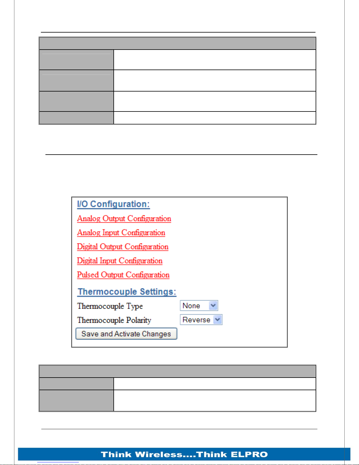
Page 98 915U-2 Wireless I/O
RS232 / RS485 Serial Port Configuration
RS232 / RS485 Port
Data Rate
Data Format
Flow Control
Select the desired functionality. Select either Modbus TCP /
RTU or Expansion I/O
The serial data rate desired. Serial data rates available range
from 110bps to a maximum of 230,400bps.
The data format desired. All the standard data formats are
supported.
Selects CTS/RTS or None
I/O Configuration
Main I/O Configuration Selection page
From here you select the I/O type that you wish to configure.
The Thermocouple Type selection is also done from this page.
Thermocouple Type
Thermocouple
Polarity
Page 98 915U-2 Wireless I/O
Selects the type of Thermocouple.
Selects the Thermocouple Polarity, Normal, or Reverse.
Figure 61 – I/O Configuration
Thermocouple Settings
Page 100
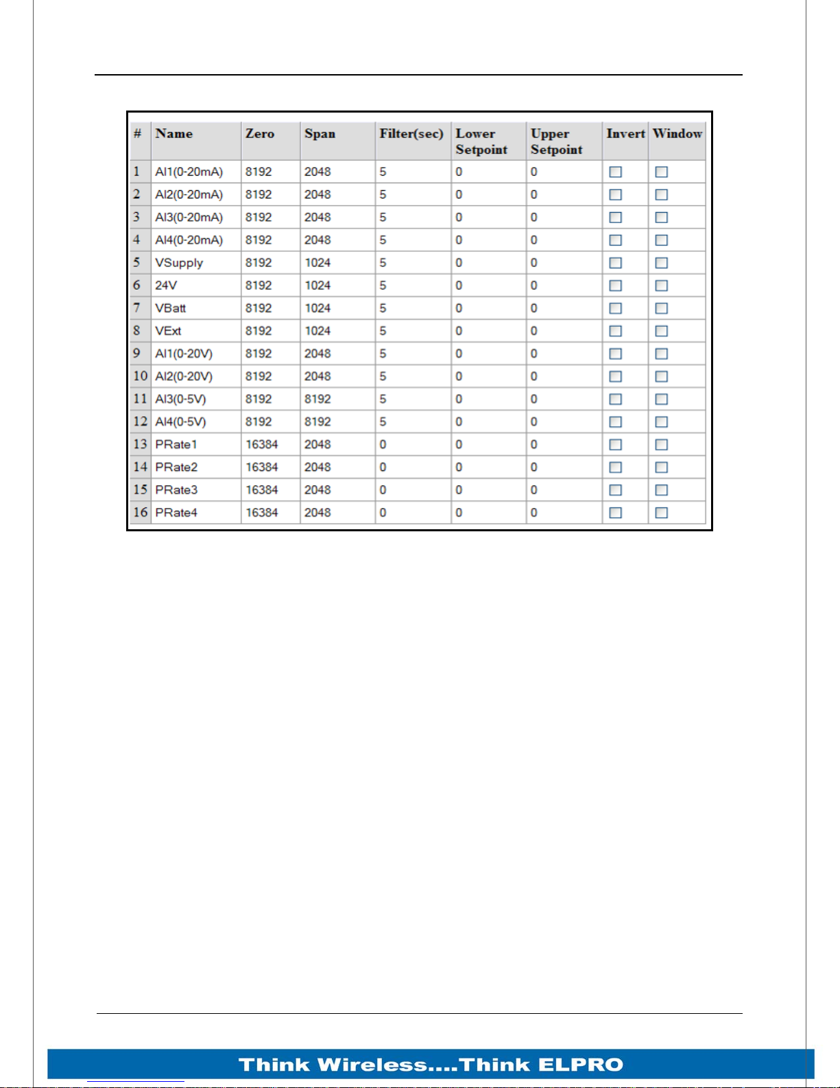
915U-2 Wireless I/O Page 99
Analog Inputs
Figure 62 – Analog Input Configuration
The 915U-2 Analog inputs have the following configuration parameters.
Name – The inputs can be named to help with configuration or use the default, up to 30
characters including spaces.
Zero / Span – These variables will change the Scale of the Analog Inputs.
Zero – Starting Value (counts) when measured value is zero
Span – Number of counts per measured value (mA, V, Hz, etc)
Filter (sec) – The Filter time Constant is the time the analog takes to settle on a step
changed of an analog value. By default, all the inputs except the Pulse Rates have a
Time constant of 5 seconds. Pulsed input rates are not filtered.
Lower & Upper Setpoints – The Setpoint is a discrete signal that is controlled using the
Upper and Lower Setpoints, Invert and Window selection boxes. All the analogs have
these controls and they can be used to turn on an output locally or at a remote location.
The internal setpoint status must be mapped to a remote output for this option to have
effect.
The two main Setpoint control options are.
Deadband (Default) - If the Analog Input is greater than the Upper Set
point, the set-point status will be active (on, “1”). The setpoint will reset
(off, “0”) when the Analog Input is less than the Lower Set Point. Note that
the Upper Set Point must always be higher than the Lower Set Point.”
Windowed – If the analog value is inside the upper and lower setpoints,
the setpoint will be active (on, “1”), and if the analog value is outside of
these setpoints the setpoint will be reset (off, “0”)
Page 99 915U-2 Wireless I/O
 Loading...