


ELPRO Technologies Pty Ltd, 9/12 Billabong Street, Stafford Q 4053, Australia.
Tel: +61 7 33524533 Fax: +61 7 33524577 Email: sales@elprotech.com
Web: www.elprotech.com
User Manual
905U-G Wireless Gateway

Important Notices
MAN_905G_1.16 Page 2
Thank you for your selection of the 905G module. We trust it will give you many
years of valuable service.
ATTENTION!
Incorrect termination of supply wires may
cause internal damage and will void warranty.
To ensure your 905G enjoys a long life,
double check ALL your connections with
the user’s manual
before turning the power on.
Caution!
For continued protection against risk of fire, replace the module fuse F1 only with
the same type and rating.
CAUTION:
To comply with FCC RF Exposure requirements in section 1.1310 of the FCC Rules, antennas
used with this device must be installed to provide a separation distance of at least 20 cm from
all persons to satisfy RF exposure compliance.
DO NOT:
• operate the transmitter when someone is within 20 cm of the antenna
• operate the transmitter unless all RF connectors are secure and any open connectors are
properly terminated.
• operate the equipment near electrical blasting caps or in an explosive atmosphere
All equipment must be properly grounded for safe operations. All equipment should be serviced
only by a qualified technician.

905U-G Wireless Gateway User Manual
Page 3©September 2004
FCC Notice:
This user’s manual is for the ELPRO 905U-G radio telemetry module. This device complies with
Part 15.247 of the FCC Rules.
Operation is subject to the following two conditions:
1) This device may not cause harmful interference and
2) This device must accept any interference received, including interference that may cause
undesired operation.
This device must be operated as supplied by ELPRO Technologies Pty Ltd. Any changes or
modifications made to the device without the written consent of ELPRO Technologies Pty. Ltd.
May void the user’s authority to operate the device.
End user products that have this device embedded must be supplied with non-standard antenna
connectors, and antennas available from vendors specified by ELPRO Technologies. Please
contact ELPRO Technologies for end user antenna and connector recommendations.
Notices: Safety
Exposure to RF energy is an important safety consideration. The FCC has adopted a safety
standard for human exposure to radio frequency electromagnetic energy emitted by FCC regulated
equipment as a result of its actions in Docket 93-62 and OET Bulletin 65 Edition 97-01.
CAUTION:
To comply with FCC RF Exposure requirements in section 1.1310 of the FCC Rules, antennas
used with this device must be installed to provide a separation distance of at least 20 cm from all
persons to satisfy RF exposure compliance.
DO NOT:
• operate the transmitter when someone is within 20 cm of the antenna
• operate the transmitter unless all RF connectors are secure and any open connectors are
properly terminated.
• operate the equipment near electrical blasting caps or in an explosive atmosphere
All equipment must be properly grounded for safe operations. All equipment should be serviced
only by a qualified technician.

Important Notices
MAN_905G_1.16 Page 4
Important Notice
ELPRO products are designed to be used in industrial environments, by experienced industrial
engineering personnel with adequate knowledge of safety design considerations.
ELPRO radio products are used on unprotected license-free radio bands with radio noise and
interference. The products are designed to operate in the presence of noise and interference,
however in an extreme case, radio noise and interference could cause product operation delays or
operation failure. Like all industrial electronic products, ELPRO products can fail in a variety of
modes due to misuse, age, or malfunction. We recommend that users and designers design
systems using design techniques intended to prevent personal injury or damage during product
operation, and provide failure tolerant systems to prevent personal injury or damage in the event
of product failure. Designers must warn users of the equipment or systems if adequate protection
against failure has not been included in the system design. Designers must include this Important
Notice in operating procedures and system manuals.
These products should not be used in non-industrial applications, or life-support systems, without
consulting ELPRO Technologies first.
1. For 905G modules, a radio license is not required in most countries, provided the module
is installed using the aerial and equipment configuration described in the 905U Installation
Guide. Check with your local 905G distributor for further information on regulations.
2. For 905G modules, operation is authorized by the radio frequency regulatory authority in
your country on a non-protection basis. Although all care is taken in the design of these
units, there is no responsibility taken for sources of external interference. The 905U
intelligent communications protocol aims to correct communication errors due to
interference and to retransmit the required output conditions regularly. However some
delay in the operation of outputs may occur during periods of interference. Systems
should be designed to be tolerant of these delays.
3. To avoid the risk of electrocution, the aerial, aerial cable, serial cables and all terminals of
the 905G module should be electrically protected. To provide maximum surge and
lightning protection, the module should be connected to a suitable earth and the aerial,
aerial cable, serial cables and the module should be installed as recommended in the
Installation Guide.
4. To avoid accidents during maintenance or adjustment of remotely controlled equipment,
all equipment should be first disconnected from the 905U module during these
adjustments. Equipment should carry clear markings to indicate remote or automatic
operation. E.g. "This equipment is remotely controlled and may start without warning.
Isolate at the switchboard before attempting adjustments."
5. The 905G module is not suitable for use in explosive environments without additional
protection.

905U-G Wireless Gateway User Manual
Page 5©September 2004
Limited Warranty, Disclaimer and Limitation of
Remedies
ELPRO products are warranted to be free from manufacturing defects for a period of 2 years
from the effective date of purchase. The effective date of purchase is decided solely by
ELPRO Technologies.
This warranty does not extend to:
- failures caused by the operation of the equipment outside the particular product's
specification, or
- use of the module not in accordance with this User Manual, or
- abuse, misuse, neglect or damage by external causes, or
- repairs, alterations, or modifications undertaken other than by an authorized Service
Agent.
ELPRO’s liability under this warranty is limited to the replacement or repair of the product.
This warranty is in lieu of and exclusive of all other warranties. This warranty does not
indemnify the purchaser of products for any consequential claim for damages or loss of
operations or profits and ELPRO is not liable for any consequential damages or loss of
operations or profits resulting from the use of these products. ELPRO is not liable for
damages, losses, costs, injury or harm incurred as a consequence of any representations,
warranties or conditions made by ELPRO or its representatives or by any other party, except as
expressed solely in this document.
How to Use This Manual
To receive the maximum benefit from your 905G product, please read the Introduction,
Installation and Operation chapters of this manual thoroughly before using the 905G.
Chapter Four Configuration explains how to configure the modules using the Configuration
Software available.
Chapter Six Troubleshooting will help if your system has problems.
The foldout sheet 905U-G Installation Guide is an installation drawing appropriate for most
applications.

Contents
MAN_905G_1.16 Page 6
CONTENTS
CHAPTER 1 INTRODUCTION 9
1.1 905G OVERVIEW 9
1.1.1 Modbus / DF1 905G 10
1.1.2 Profibus 905G 10
1.1.3 Ethernet 905G 11
1.1.4 DeviceNet 905G 12
1.1.5 Modbus Plus 905G 12
1.2 T
HE 905G STRUCTURE 13
1.2.1 On-board I/O 14
1.2.2 I/O Expansion - 105S modules 14
1.3 T
HE WIRELESS NETWORK 14
1.3.1 905U to 905G Network 14
1.3.2 905G to 905G Network 15
1.3.3 “Data Concentrator” Networks 16
1.3.4 905G Repeaters 17
CHAPTER 2 OPERATION 19
2.1 START-UP 19
2.2 O
PERATION 19
2.3 D
ATABASE 21
2.4 T
HE HOST - 905G LINK 22
2.4.1 Modbus / DF1 22
2.4.2 Profibus 23
2.4.3 Ethernet 23
2.5 R
ADIO SYSTEM DESIGN 23
2.5.1 Radio Signal Strength 24
2.5.2 Repeaters 24
2.6 R
ADIO COMMS FAILURE 24
2.6.1 Monitoring Communications Failure 25
2.7 S
ECURITY CONSIDERATIONS 26
CHAPTER 3 INSTALLATION 27
3.1 GENERAL 27
3.2 A
NTENNA INSTALLATION 27
Dipole and Collinear antennas. 29
3.2.2 Yagi antennas. 29
3.3 P
OWER SUPPLY 33
3.3.1 AC Supply 33
3.3.2 DC Supply 33
3.3.3 Solar Supply 33
3.4 I
NPUT / OUTPUT 33
3.4.1 Digital Inputs / Outputs 33
3.5 S
ERIAL PORT 33
3.5.1 RS232 Serial Port 33
3.5.2 RS485 Serial Port 34
3.6 P
ROFIBUS PORT 36
3.7 E
THERNET PORT 37
3.8 M
ODBUS PLUS PORT 38
3.9 D
EVICENET PORT 39
CHAPTER 4 CONFIGURATION 41
4.1 INTRODUCTION 41
4.2 C
ONFIGURATION PROGRAM 42
Program Operation 42

905U-G Wireless Gateway User Manual
Page 7©September 2004
4.2.2 Security 46
4.3 M
APPINGS 905G TO 905U I/O MODULES 48
4.3.1 Mappings from Inputs at Remote 905U I/O Modules 48
4.3.2 Mappings from 905G to Outputs at Remote 905U I/O Modules 50
4.3.3 Don’t Send if in Comm Fail 52
4.3.4 Startup Polls 53
4.3.5 Polls to Remote Modules 53
4.4 M
APPINGS FROM 905G TO OTHER 905G MODULES 53
4.4.1 Entering a Block Mapping 55
4.4.2 Host Device Trigger 56
4.4.3 Time Period 57
4.4.4 Real-Time 58
Change-of-State 60
4.4.6 Mixing Normal Mappings and Block Mappings 60
4.4.7 Comms Fail for Block Mappings 60
“Repeater-only” Configuration 61
4.5 C
HANGE SENSITIVITY 61
4.6 S
ERIAL CONFIGURATION - MODBUS 63
4.6.1 MODBUS Slave 63
4.6.2 MODBUS Master 65
4.7 S
ERIAL CONFIGURATION - DF1 68
4.8 F
IELDBUS CONFIGURATION 73
Fieldbus Mappings 74
4.9 F
IELDBUS CONFIGURATION - PROFIBUS SLAVE 79
4.10 F
IELDBUS CONFIGURATION - PROFIBUS MASTER 80
4.10.1 GSD File 80
4.10.2 Protocol and Supported Functions 80
4.10.3 Configuration 81
4.10.4 Message Interface 92
Error Codes 112
DPV1 Return Codes 113
4.11 F
IELDBUS CONFIGURATION - ETHERNET 113
4.11.1 Setting IP Address 114
4.11.2 Modbus TCP 116
4.11.3 EtherNet/IP 119
4.12 F
IELDBUS CONFIGURATION – DEVICENET 123
4.12.1 DeviceNet Introduction 123
4.12.2 DeviceNet Address Setting 123
4.12.3 EDS File 123
4.12.4 Protocol and Supported Functions 124
4.13 F
IELDBUS CONFIGURATION – MODBUS PLUS 124
4.13.1 Modbus Plus Introduction 124
4.13.2 Modbus Plus Addressing 124
4.13.3 Protocol & Supported Functions 125
4.13.4 Configuration 126
4.14 C
ONNECTING 105S SERIAL I/O 128
4.15 U
PLOADING AND DOWNLOADING 129
4.15.1 Loading from a 905G 129
CHAPTER 5 SPECIFICATIONS 131
CHAPTER 6 DIAGNOSTICS 133
6.1 DIAGNOSTICS CHART 133
6.2 D
IAGNOSTICS MENU 134
6.3 E
THERNET DIAGNOSTICS 141

Contents
MAN_905G_1.16 Page 8
6.4 FIELDBUS INDICATING LEDS 143
CHAPTER 7 WARRANTY 149
APPENDIX 1 STATUS REGISTERS 151
APPENDIX 2 IT FUNCTIONALITY 153

905U-G Wireless Gateway User Manual
Page 9©September 2004
Chapter 1 INTRODUCTION
1.1 905G Overview
The 905U-G Wireless Gateway products provide a wireless interface between various
fieldbus protocols used in process and automation
applications. The 905U-G includes an integral
900MHz license-free radio transceiver, and
transfers transducer and control signals (I/O) using
a highly secure and highly reliable radio protocol.
The 905U radio protocol is designed for very
efficient radio band usage, with event reporting
communications, automatic acknowledgment and
error-correction, peer to peer addressing, multiple
path routing, and frequency encoding and data
encryption for system security.
Application types include:
• The 905U-G interfaces between 905U wireless
I/O and various fieldbus protocols. Connect
wireless I/O to PLC’s, DCS, SCADA or
Internet.
• Wireless extension of factory automation buses
such as Profibus.
• Wireless interconnectivity between different
fieldbuses - Ethernet to Profibus to Modbus to
DF1.
• Combined networks of the above.
The 905U-G has eight on-board discrete I/O. Each
I/O point can be configured individually as a contact input signal, or a discrete output signal.
Input signals can sent via its fieldbus connection to a host device (PLC, DCS etc) or be
transmitted by radio to other 905U units. The output signals can be driven by a host device,
or linked to inputs on remote 905U units.
This document assumes the reader is familiar with the operation of the 905U I/O modules for further information, please refer to the User Manuals for these products.
Profibus
Ethernet
Modbus
DF1
Internet
905U I/O
905U I/O
Direct I/O
905U-G
Direct I/O
905U-G
Profibus
905U-G
Profibus
905U-G
Profibus
Ethernet
905U I/O
905U I/O
Direct I/O
905U-G
Direct I/O
Profibus
Modbus
905U-G
905U-G
905U-G
Modbus
905U-G
Ethernet
905U-G
Profibus

Chapter One Introduction
MAN_905G_1.16 Page 10
The 905U-G is referred to as the 905G for the rest of this document, to clearly differentiate
from normal 905U I/O modules.
Ordering information:
905U-G-MD1 Modbus Master & Slave / DF1 interface
905U-G-PR1 Profibus-DP Slave interface
905U-G-PR2 Profibus-DP Master interface
905U-G-ET1 Ethernet interface - Modbus TCP, Ethernet IP, FTP, HTML, Email
905U-G-DE1 DeviceNet Slave interface
905U-G-M+1 Modbus Plus Slave interface
1.1.1 Modbus / DF1 905G
The 905U-G-MD1 can be configured for Modbus master interface, Modbus slave, or DF1.
Modbus is a Master-Slave protocol originally developed by Modicon (now part of the
Schneider group). It became a popular interconnect protocol with many equipment
manufacturers. One Modbus master controls the Modbus network communications, which
can comprise up to 250 Modbus slave devices. The Modbus master can read or write I/O
values to/from Modbus slaves. The 905G can be configured as either Modbus Master or
Modbus Slave. The variation of Modbus supported by the 905G is “Modbus RTU” (also
known as “Modbus binary”).
DF1 is an Allen-Bradley protocol (Allen-Bradley is now part of the Rockwell Automation
group). DF1 offers both full-duplex (point to point) and half-duplex (multidrop) operation.
The 905G only supports the full-duplex operation - this is the default DF1 mode on most
equipment. DF1 full-duplex is a “peer-to-peer” protocol. Either DF1 device can initiate
commands to the other device, and both devices will respond to commands from the other
device.
The 905U-G-MD1 has two serial connections - RS232 and RS485, on the bottom end plate
of the module. The serial port provides both RS232 and RS485 hardware connections,
however both connections are paralleled internally - both connections cannot be used at the
same time. Either RS232 or RS485 can be used for Modbus communications, however only
the RS232 port can be used for DF1. The serial port must be configured to suit the host
device. Serial data rates between 1200 and 19200 baud may be selected, and character types
with 7 or 8 data bits, even/odd/none parity, and 1 or 2 stop bits may be selected.
The Modbus/DF1 905G has 4300 general-purpose I/O registers. Each discrete, analog and
pulse I/O point takes up one register.
1.1.2 Profibus 905G
The Profibus 905G provides Profibus-DP Slave functionality according to EN 50170.
Profibus is a popular automation fieldbus that originated in Germany and is used extensively
by Siemens and other automation suppliers.
The Profibus connection on the 905G is optically isolated RS485 using an on-board DC/DC
converter. The Profibus port has automatic baudrate detection (9600 bit/s - 12 Mbit/s).
The Profibus Slave 905G (PR1) will connect to a Profibus LAN controlled by an external
master device. The Profibus Master 905G (PR2) will control communications on a Profibus
LAN, and can connect to up to 125 Profibus slave devices.

905U-G Wireless Gateway User Manual
Page 11 ©September 2004
The Profibus 905G I/O database has 4300 registers (each of 16 bit value), however the
Profibus interface limits the amount of I/O that can be transferred via the Profibus port.
Slave unit (PR1). The PR1 slave unit only supports 416 x 8 bit bytes of I/O. Of the 416
bytes of I/O, there is a maximum 244 input bytes and maximum 244 output bytes - that is,
if 244 input bytes are used then only 172 output bytes can be used (416 – 244). Each byte
can represent 8 discrete inputs or outputs, or an 8-bit value, or two bytes can represent a 16bit value. That is, analog or pulse I/O can be transferred as 8-bit registers (1 byte) or 16-bit
registers (2 consecutive bytes).
An “output” is a value coming into the 905G via the fieldbus (that is, a value written to the
905G from the Profibus master). An input is a value going out from the 905G via the
fieldbus (a value read by the Profibus master).
So a Profibus Slave 905G could handle up to 1952 (244 x 8) discrete inputs or 244 low
resolution analog inputs or 122 (244 x ½) high resolution analog inputs, or some combination
in between.
For example, a Profibus 905G can handle 400 discrete inputs, 240 discrete outputs, 90
analog inputs and 60 analog outputs (assume analogs are 16-bit). The number of input bytes
is 230 (400/8 + 90*2). The number of output bytes is 150 (240/8 + 60*2). The total number
of I/O bytes is 380. If the number of analog outputs was increased to 90, then the total
output bytes would be 210 (240/8 + 90*2), and the total number of I/O bytes is 440 - this
exceeds the capacity of the Profibus interface.
Master unit (PR2). The Profibus master interface supports 2048 input bytes and 2048 output
bytes. Each byte can be 8 discrete inputs or outputs, but analog or pulse I/O take up 1 byte
for low resolution values (8-bit) or 2 bytes for high resolution values (16-bit).
So a Profibus Master 905G can handle up to 4300 I/O total, but analog or pulse inputs are
limited to 2048 x 8-bit values or 1024 x 16-bit values. The same limit applies to outputs.
For example, a Profibus Master 905G can handle 2000 discrete inputs and 500 analog inputs
(assume analogs are 16-bit). The number of input bytes is 1250 (2000/8 + 500*2). The
same unit could handle 4000 discrete outputs and 750 analog outputs. The number of output
bytes is 2000 (4000/8 + 750*2). The total number of I/O is 3250 which is less than the total
limit of 4300.
1.1.3 Ethernet 905G
The Ethernet 905G provides several different types of Ethernet functionality:
♦ Modbus TCP. Modbus TCP uses Modbus as a base protocol within an Ethernet
communications structure. The 905G provides class 0, 1 and partially class 2 slave
functionality.
♦ EtherNet IP. EtherNet IP is the version of Ethernet used by Allen-Bradley devices. The
905G provides level 2 I/O server CIP (ControlNet and DeviceNet).
♦ Internet functionality. The 905G has 1.4Mbyte of non-volatile “flash” memory for
embedded web “pages” (dynamic HTTP), on-board file system, user downloadable web
pages thru FTP server, and email functionality (SMTP).
The Ethernet connection is a transformer isolated RJ45 connector, 10/100 Mbit/sec.
The Ethernet 905G I/O database has 4300 registers (each of 16 bit value), however the
Ethernet interface only supports 2048 input bytes and maximum 2048 output bytes. Each

Chapter One Introduction
MAN_905G_1.16 Page 12
byte can be 8 discrete inputs or outputs, but analog or pulse I/O take up 1 byte for low
resolution values (8-bit) or 2 bytes for high resolution values (16-bit).
An “output” is a value coming into the 905G via the fieldbus. An input is a value going out
from the 905G via the fieldbus.
So an Ethernet 905G can handle up to 4300 I/O total, but analog or pulse inputs are limited
to 2048 x 8-bit values or 1024 x 16-bit values. The same limit applies to outputs.
For example, an Ethernet 905G can handle 2000 discrete inputs and 500 analog inputs
(assume analogs are 16-bit). The number of input bytes is 1250 (2000/8 + 500*2). The
same unit could handle 4000 discrete outputs and 750 analog outputs. The number of output
bytes is 2000 (4000/8 + 750*2). The total number of I/O is 3250 which is less than the total
limit of 4300.
1.1.4 DeviceNet 905G
The DeviceNet 905G provides DeviceNet 2.0 Slave functionality. DeviceNet is an
automation fieldbus developed by Allen-Bradley (Rockwell Automation).
The DeviceNet connection on the 905G is optically isolated RS422 with selectable baudrate
between 125 and 500 Kbit/sec.
The 905G I/O database has 4300 registers (each of 16 bit value), however the DeviceNet
interface only supports 512 x 8 bit input bytes and 512 x 8 bit output bytes, and this limits
the amount of I/O that can be transferred via the DeviceNet port.
Each byte can represent 8 discrete inputs or outputs, or an 8-bit value, or two bytes can
represent a 16-bit value. That is, analog or pulse I/O can be transferred as 8-bit registers (1
byte) or 16-bit registers (2 consecutive bytes).
An “output” is a value coming into the 905G via the fieldbus (that is, a value written to the
905G from the DeviceNet master). An input is a value going out from the 905G via the
fieldbus (a value read by the DeviceNet master).
So a DeviceNet 905G can normally handle up to 4096 (512 x 8) discrete inputs or 512 low
resolution analog inputs or 256 (512 x ½) high resolution analog inputs, or some combination
in between. It can also handle the same number of outputs, however the total I/O count
cannot exceed the 905G database size of 4300.
1.1.5 Modbus Plus 905G
The Modbus Plus 905G provides Modbus Plus Slave functionality. The Modbus Plus
connection on the 905G is optically isolated RS485 with standard baudrate of 1 Mbit/sec.
The 905G I/O database has 4300 registers (each of 16 bit value), however the Modbus Plus
interface only supports 1024 input registers and maximum 1024 output registers. Each
register can be 16 discrete inputs or outputs, or one analog or counter 16-bit value.
An “output” is a value coming into the 905G via the fieldbus. An input is a value going out
from the 905G via the fieldbus.
So an Modbus Plus 905G can handle up to 4300 I/O total, but analog or pulse inputs are
limited to 1024 x 16-bit values. The same limit applies to outputs.
The Modbus Plus interface allows global data base transactions with routing for up to six
Modbus Plus networks.

905U-G Wireless Gateway User Manual
Page 13 ©September 2004
1.2 The 905G Structure
The 905G has three functional sections:
• The Radio Interface consists of an I/O database (or "Process Image") that maintains the
latest values of all I/O in the wireless I/O system. The I/O database comprises 4300 x 16
bit I/O registers and 4300 x 16 bit status registers. There are also other registers in the
database that can be used for system management - they are discussed later in this
manual. NOTE – the terms ‘Radio Interface’ and ‘I/O database’ are used interchangeably
throughout the manual.
• The radio port allows the 905G to communicate with other 905G and/or 905U modules
using the 905U protocol (called “ELPRO 905U”). Messages from the 905U modules are
received by the radio port and used to update the input values in the 905G Radio Interface.
The radio port also creates the correct radio message to set outputs on the remote 905U
modules.
The ELPRO 905U protocol is an extremely efficient protocol for radio communications.
Radio messages can be sent using exception reporting - that is, when there is a change of
an input signal - or by read/write messages. Each message can comprise a single I/O
value, or multiple I/O values (termed a “block” of I/O). There are also update messages,
which are sent for integrity purposes. Messages include error checking, with the
destination address sending a return acknowledgment. Up to five attempts are made to
transmit the message if an
acknowledgment is not received.
The ELPRO 905U protocol is
designed to provide reliable radio
communications on an open
license-free radio channel.
• The Fieldbus port enables
communications between a host
device, which could be a PLC,
DCS, HMI, intelligent transducer,
etc), and the 905G Radio Interface
database. A “host device” may be
one or several devices connected to
the same fieldbus or network (for
example, an Ethernet LAN) - in this manual, the LAN is considered as a “host device”.
The fieldbus port decodes messages from the host device and reads or writes I/O values to the
database. The fieldbus port can also generate messages to the host device.
The 905G I/O database effectively isolates the fieldbus and the radio network. This provides
a high level of system performance. The 905U radio protocol is very efficient and reliable
for radio communications. It minimizes radio channel usage by "change-of-state" reporting,
and allows the use of intermediate repeater addresses. It also allows peer-to-peer (905U to
905U, 905G to 905G) and peer-to-master (905U to 905G) communications. PLC protocols,
by comparison, are designed to provide transfer of large I/O files by "wire" link. The 905G
retains the advantage of both protocols in their respective communications media.
FIELDBUS
INTERFACE
FIELDBUS
PROFIBUS
ETHERNET
MODBUS
DF1
DEVICENET
MODBUS +
RADIO
PORT
RADIO
INTERFACE
I/O
DATABASE
905U
RADIO
INTERFACE
905U-G
ON-BOARD I/O
EIGHT DISCRETE I/ O SIGNALS

Chapter One Introduction
MAN_905G_1.16 Page 14
1.2.1 On-board I/O
The 905G has eight on-board discrete I/O. Each I/O point can be used as either a discrete
input (voltage free contact input) or discrete output (transistor output) - an I/O point cannot
be used as both input and output. Each I/O point is linked to two separate I/O registers in the
database - one for the “input” function and one for the “output” function.. If the output
register is set “on” by the fieldbus or by a radio message from a remote module, then the
905G will automatically set the input register for the same I/O point to “off”. This means that
the output register has priority over the input register - if there is a conflict, the input value
is ignored.
The 905G also has three internal inputs linked to I/O registers:
♦ Supply voltage status - if the normal supply fails, this status is set on.
♦ Low battery voltage. The 905G has an internal battery charger to trickle charge a back-
up battery. If the battery voltage is low, this status is set.
♦ Battery voltage - the actual value of the connected battery voltage.
1.2.2 I/O Expansion - 105S modules
The 905G provides eight on-board discrete I/O. Where additional I/O is required, 105S
modules can be connected to the RS485 port of the 905G modules.
Note: 105S modules cannot be connected to the 905U-G-MD1 unit (as this unit uses the
RS485 port for Modbus or DF1 communications), unless this unit is configured as
“Repeater-only” and does not have a host device connected.
1.3 The Wireless Network
The 905G can communicate with up to 490 other addresses - this could be 490 other 905U
modules, or in the case of 905K modules, it could be many thousands of modules (as many
905K modules can share the same address). 905G modules may take up more than one
address under some circumstances.
Any 905G or 905U module can act as a radio repeater for other modules - that is, radio
messages can be passed onto other modules. Up to five repeater addresses can be configured
for messages transmitted to a 905G module.
Each module can have a unit address between 1 – 95, but the 905G also recognizes repeater
addresses in conjunction with the unit address as the module “identifier”. Hence module #2
is recognized as different to #2 via #57 - #57 being a repeater.
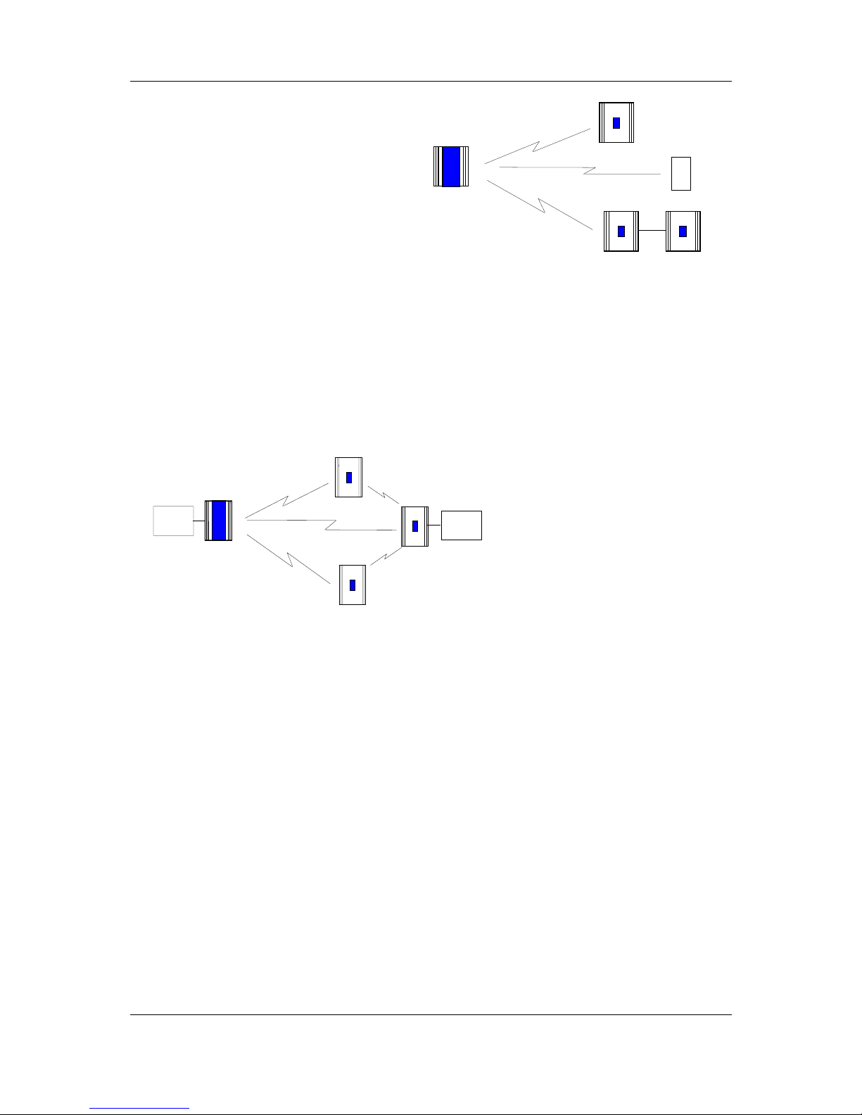
1.3.1 905U to 905G Network
In the wireless I/O system, the 905G acts as a normal 905U module (this covers 905U I/O,
105S I/O, 905U-K and 905U-C modules).
905U modules transmit messages to the 905G address and the 905G acknowledges these
messages like a normal 905U module. When a 905G transmits messages to change remote
outputs, it will "re-try" if it does not receive an acknowledgment, like a normal 905U module.
Remote 905U modules can connect to 105S modules in the normal way. The 905G host can
access I/O on 105S modules by using the intermediate 905U as a repeater.
905U-G Wireless Gateway User Manual
Page 15 ©September 2004
905U modules can transmit input
messages directly to outputs on other
905U module, as well as the 905G. The
same input can be transmitted to different
addresses by entering two "mapping"
configurations at the remote module.
Normal 905U Messages
I/O registers in a 905G can be configured
(mapped) to outputs at remote 905U
modules, or I/O registers in 905G
modules. The 905G will transmit an I/O message when a “change-of-state” occurs for that
I/O register . Registers have a configurable “sensitivity” value - this determines how much
the register value has to change to trigger a change message. A change-of-state occurs when
the register value has changed by more than the sensitivity value since the last transmission.
The 905G also transmits periodic update messages if there has been no change - if an I/O
register is mapped to a remote output or another 905G, then that register can be configured
with an update time.
905G modules can transmit to 905G modules as well as other 905G modules. There can be
multiple 905G and 905C modules in a network - as well as 905U I/O. Because the 905U
protocol is peer-to-peer, there are few constraints on communications between multiple 905U
modules.
Poll Messages
A 905G can also generate poll messages to remote 905U modules. These poll messages act in
the same way as a start-up poll - the remote module immediately responds with update
messages for any I/O mappings configured to the 905G.
Poll messages can be triggered by:
♦ time period, configurable 1 – 4096 sec (1.1 hour), or
♦ real time clock, or
♦ on demand by the host device, by writing to a “trigger register” in the 905G
1.3.2 905G to 905G Network
Different types of 905G modules can communicate - for example, a Modbus 905G can
communicate with an Ethernet 905G. I/O registers in one 905G can be transmitted to I/O
registers in another 905G. When the 905G is configured, “mappings” can be entered linking
I/O registers to registers in another 905G.
905U-G
905U-3
905U-1
105S-2
905U-K
905U-G
905U-3
905U-1
PLC
905U-C
PLC

Chapter One Introduction
MAN_905G_1.16 Page 16
As well as the normal “I/O change” messages and update messages, the 905G has “block
read” and “block write” messages for use with other 905G modules. These messages will
transmit multiple register values instead of only one as in the normal 905U message. The
block read/write messages increase the efficiency of radio communications where a 905G
“sees” a large number of changes in its database at the one time. For example, if a host
writes a block of 100 signal values to a 905G, and 20 of these values have changed since the
last write-operation. If the block is mapped to another 905G, then the 905G can transmit all
20 values in one radio message, instead of 20 messages.
Normal I/O messages can be repeated by any type of 905U I/O module, however block
read/write messages can only be repeated by other 905G modules.
Block Read Message
A block read message is a request to another 905G to transmit the values of a consecutive
block of registers. The destination 905G will respond with the values, which will be stored in
a corresponding block of registers in the originating 905G. A block read message can be
triggered by:
♦ time period, configurable 1 – 4096 sec (1.1 hour), or
♦ real time clock, or
♦ on demand by the host device, by writing to a “trigger register” in the 905G.
Block Write Message
A block write message transmits a consecutive block of register values from one 905G to a
destination 905G. It can be triggered by:
♦ time period, configurable 1 – 4096 sec (1.1 hour), or
♦ real time clock, or
♦ on demand by the host device, by writing to a “trigger register” in the 905G, or
♦ a change-of-state event occurring within the block of I/O registers.
If a block write message has been configured to be transmitted on change-of-state, a “time
window” is configured. When a change-of-state occurs in one of the registers in the block,
the time window will be activated. All changes during the time window will be grouped
together and transmitted as one block write message. That is, the block write message will
not be sent immediately the first change-of-state occurs (unless the time window is
configured to zero), but will be sent at the end of the time window - any other registers in
the block that change during the time window will be sent as part of the same message. The
time window can be configured from 0 – 255 seconds.
1.3.3 “Data Concentrator” Networks
905G units can act as “data concentrator” units to collect I/O from a local network of 905U
wireless I/O modules and pass the I/O on to another 905G as a block.

905U-G Wireless Gateway User Manual
Page 17 ©September 2004
This type of network reduces the amount of radio traffic and is suitable for systems with a
large number of I/O modules. The system is divided into local sub-networks, each with a
905G unit. The 905U modules transmit their I/O vlaues to the 905G. The 905G then
transfers these values to the “central” 905G using a block transfer which is very efficient
compared to a lot of individual I/O transmissions.
The data concentrator network is different than using the 905G as a repeater. A repeater retransmits each message in the same format. A data concentrator collects the I/O values as a
block, and transmits the complete block in one transmission.
1.3.4 905G Repeaters
Any 905U module can repeat a normal radio message, however only 905G modules can
repeat a block message. 905G units connected to a host device can also act as a repeater for
other modules.
Where a 905G is being used without a host device as a repeater or data-concentrator, it can
be configured as “Repeater-only”. This allows the RS232/485 port to be used for on-line
diagnostics. If the unit is a 905U-G-MD1, the “Repeater-only” configuration also allows
this module to connect to 105S serial I/O modules.
TO HOST
DEVICE
NETWORK OF
905U I/O UNITS
905U-G
905U-G
NETWORK OF
905U I/O UNITS
905U-G

905U-G Wireless Gateway User Manual
Page 19 ©September 2004
Chapter 2 OPERATION
2.1 Start-up
The 905G operating software and the database configuration are stored in non-volatile
memory, however the database I/O register values are lost on power failure (in the same way
as a PLC).
On start-up, the 905G sends "start-up poll" messages to remote modules based on the source
address of inputs configured in the database (the start-up messages can be disabled by
configuration). The remote modules respond with update messages for their inputs, which
sets initial values in the 905G I/O database registers. The 905G provides a delay of 5
seconds between each start-up poll, to allow the remote module to respond and to avoid
overloading the radio channel.
If there are a lot of remote modules, then this start-up stage may take a significant time, and
this should be allowed for in the system design. The 905G has an internal battery charger
feature and the use of a back-up battery should be considered if this start-up delay presents a
constraint to system reliability. Start-up polls may be disabled for individual remote modules
in the database configuration.
For the host device, the 905G provides an "Active" signal on the RS232 port (DCD pin 1).
Its purpose is to indicate to the host that the 905G is now processing output messages for the
remote modules. When the 905G powers down (or should an internal fault occur), the
"Active" signal resets (turn “off” or “0”). When the 905G starts-up, it holds the "Active"
signal in a reset condition (“off” or “0”) for a time equal to the number of remote addresses
(or modules) configured times 5 seconds plus any delay if remote addresses are offline. For
example, if there are 20 remote addresses configured in the 905G database, then the “active”
signal will be held in the reset state for 100 seconds (20 x 5). During this period, the 905G
will not change any output values in its database. After this time, the 905G will set the
"Active" signal (to “on” or “1”) - the host can then send messages to the 905G to update the
output values in the database.
2.2 Operation
The 905G database can hold values for 4300 I/O signals plus the 8 on-board I/O. The
database registers (also called I/O registers) can be accessed by both the radio port and the
fieldbus port. The host device can change values in the database via the fieldbus, and the
905G can transmit radio messages out with the new values. Radio messages can be received
with new values for database registers, and these new values can be written to the host device
or read by the host device, via the fieldbus.
The 905G operation must be configured before the 905G will function. Configuration is
achieved by creating a configuration file on a PC and downloading this file to the 905G. The
905G configuration may also be "uploaded" to a PC for viewing and modification. For more
information, refer to the Configuration section of this document.
Each I/O register in the 905G database has a 16-bit value. It doesn’t matter if the remote I/O
is digital (discrete), analog or pulse. The host protocol driver in the 905G will convert the 16
bit value into a value that the host will understand. For example, if the host device requests a

Chapter Two Operation
MAN_905G_1.16 Page 20
binary/digital read command, the 905G will convert the 16 bit value into a binary (1 bit)
value before it responds.
An example of normal operation - assume that a remote module has address 14 and the
905G is address 1. Module #14 is configured with a mapping DI1 → I/O Reg 76 at #1.
When DI1 turns "on", module #14 transmits a message. If the 905G can hear this message, it
will transmit an acknowledgment back to module #14, and updates the value of I/O register
76 in the 905G database. The host device can read I/O register 76 via the data-bus, or the
905G may write the value of I/O register 76 to the host device.
I/O registers that receive values from other 905U or G modules via radio are configured with
a “Communications fail time”. If the 905G does not receive a message for this I/O register
within the comms-fail time, then the I/O register is given a “comms fail” status which the
host device can read.
I/O registers that transmit out to other 905U or G modules are configured with an “update
time” and a “sensitivity”. The 905G will transmit a message to the configured remote output
whenever the I/O register value changes by the sensitivity amount – if it has not changed
within the update time, the 905G will send a message anyway. The 905G will make five
attempts to send a message - if it does not receive an acknowledgment from the remote
module, then the I/O register is given a “comms fail” status which the host device can read.
Each I/O register has an associated “status” register, which includes information such as
comms-fail status. As well as each I/O register having an individual comms-fail status, each
remote module has an overall comms fail status. This status is “set” (on) whenever a commsfail occurs for an individual I/O register, and is “reset” (off) whenever a message is received
from the remote module. The 905G can be configured to not send any update messages to a
remote module if it senses that the remote module is in “comms fail” - that is, if any I/O
register associated with the remote module is in “comms fail”. It will start sending update
messages again when the 905G receives a message from the remote module. The default
configuration is that output updates ARE sent during comms fail conditions.
905U-G
905U-1
DIN1
#14
#1

905U-G Wireless Gateway User Manual
Page 21 ©September 2004
2.3 Database
The 905G database (Radio Interface) has 10 000 registers, each of 16 bit size. The structure
of the database is:
Registers Purpose
0 - 4299 I/O registers
4300 - 4399 On-board I/O
4401 - 4499 Comms-fail status and radio strengths for remote modules
5000 - 9499 Status registers - 16 bit status for each I/O signal
9500 - 9999 Status registers for block read/write messages
The register numbers may be used by the Host Protocol Driver to access I/O values and I/O
status information. Each configured I/O point has a 16 bit value (in registers 0000 - 4299),
and a 16 bit status value. The status register is located at 5000 plus the I/O value register.
For example, an I/O point in register number 2560 has a status value in register number 7560
(5000 + 2560).
Details of the status register are provided in Appendix A. The most important part of the
status register is the 15th or most significant bit - this indicates comm-fail status for the I/O
register. If the most significant bit is set, then the I/O register is in comms-fail.
The host device can read the status registers. For example, the communications status of an
output configured at register number 3001 can be examined by reading register number 8001
(5000 + 3001). If the register value is greater than 32767, then the 15th bit is set, indicating
that the output has a communications failure.
2.3.1 On-board I/O and Internal I/O
The 905G has eight discrete I/O points. These may be used as inputs or as outputs. Inputs are
linked to registers 4300-4307. That is, if a contact connected to DIO1 is “on”, then register
4300 is given an “on” value. Outputs are controlled from registers 4320-4327; that is, if
register 4327 is set to an “on” value, then output DIO8 is activated.
Whenever an output register is set “on”, the corresponding input register is automatically set
“off”. For example, if register 4321 is set to “1”, the 905G will also set 4301 to “0”. This
means that if both the input and output registers corresponding to the same I/O point are used
in the configuration, then the output register has priority.
Outputs may be written to by either the host device or by a remote 905U via the radio port.
Input values can be sent to the host device or to a remote module via the radio port.
The 905G also monitors its battery voltage and supply voltage. These are stored in registers
4310 and 4311 respectively, as 16 bit values, scaled so that a value of 16384 decimal (hex
4000) corresponds to 8 V, and a value of 49152 (hex C000) corresponds to 40V.
A low battery alarm is available at register 4308. This becomes active when the battery
voltage falls below 11.3V, and clears when the battery voltage rises above 11.8V. Supply

Chapter Two Operation
MAN_905G_1.16 Page 22
voltage is also monitored, and an alarm is available at register 4309. This becomes active if
the supply voltage falls below 8.0V, and clears when the supply voltage rises above 9.0V.
I/O Register Description I/O Register Description
4300 Input value DIO 1 4320 Output value DIO 1
4301 Input value DIO 2 4321 Output value DIO 2
4302 Input value DIO 3 4322 Output value DIO 3
4303 Input value DIO 4 4323 Output value DIO 4
4304 Input value DIO 5 4324 Output value DIO 5
4305 Input value DIO 6 4325 Output value DIO 6
4306 Input value DIO 7 4326 Output value DIO 7
4307 Input value DIO 8 4327 Output value DIO 8
4308 Low battery voltage status
4309 Supply voltage fail status
4310 Battery voltage value
4311 Supply voltage value
2.4 The Host - 905G Link
For the host device, the 905G "looks" like a single device (or a "virtual PLC"), containing the
I/O for the complete wireless I/O system.
DATABASE
I/O
"VIRTUAL PLC"
DATA-BUS
“HOST DEVICE”
905U-G
2.4.1 Modbus / DF1
The user selects whether the 905U-G-MD1 should act as a Modbus Master or Modbus Slave
or DF1 device.
The data type and baud rate of the serial communications must be configured at the 905G to
match the host. Data types can be 7 or 8 bit, even/odd/no parity, with 1 or 2 stop bits. Data
rates can be 300 - 19200 baud.
The full 905G database (4300 registers) can be accessed by the Host Device.

905U-G Wireless Gateway User Manual
Page 23 ©September 2004
2.4.2 Profibus
The Profibus port has auto-detect of baud rate from 9600 bits/sec to 12Mbit/sec - no
configuration is required.
The Profibus units have internal hardware comprising the Profibus Interface. The Profibus
Interface handles all Profibus DP Network communications. The internal Radio Interface is
separate to the Profibus Interface, and handles all radio communications. I/O in the Radio
Interface is linked to I/O in the Profibus Interface in a flexible way via ESeries Configuration
Software.
The Profibus Slave interface provides a total of 416 I/O bytes, with a maximum 244 input
bytes and maximum 244 output bytes. A Profibus byte can contain 8 discrete (binary)
values, or two bytes can be used for a 16-bit analogue or pulse register. So the Profibus
interface is limited to 1952 discrete inputs or 122 analogue inputs or a combination. The
same applies for outputs.
For example, a Profibus host wants to read 800 discrete inputs (100 bytes) and write 400
discrete outputs (50 bytes). This will take up 150 bytes of the Profibus Interface, leaving 266
left. The remaining bytes could be used for 133 analogue I/O - up to 72 analogue inputs
(244 – 100 discrete input bytes) plus 61 analogue outputs - or vice-versa.
The Profibus Master interface provides a total of 2048 input bytes and 2048 output bytes. A
byte can contain 8 discrete (binary) values, or two bytes can be used for a 16-bit analogue or
pulse register. So the interface is limited to 4300 discrete inputs (the limit of the 905G
database) or 1024 analogue inputs (the limit of the HMS interface) or a combination. The
same applies for outputs.
2.4.3 Ethernet
The Ethernet port automatically handles Ethernet communications at 10 or 100 Mbit/sec. An
IP address is entered so that other Ethernet devices can recognize the 905G.
The Ethernet units have internal hardware comprising the Ethernet Interface. The Ethernet
Interface handles all Ethernet Network communications. The internal Radio Interface is
separate to the Ethernet Interface, and handles all radio communications. I/O in the Radio
Interface is linked to I/O in the Ethernet Interface in a flexible way via ESeries Configuration
Software.
The Ethernet Interface provides a total of 2048 input bytes and 2048 output bytes. An
Ethernet byte can contain 8 discrete (binary) values, or two bytes can be used for a 16-bit
analog or pulse register. So the Ethernet Interface is limited to 4300 discrete inputs (the limit
of the 905G database) or 1024 analog inputs (the limit of the Ethernet interface) or a
combination. The same applies for outputs.
For example, an Ethernet host wants to read 500 analog inputs (1000 bytes). The remaining
input bytes (1548) could be used for 12,384 discrete inputs - but the 905G database is not
this big. Provided there are no outputs required, there could be 3800 discrete inputs (4300 –
500 analogs). If there are outputs required, then the number of discrete inputs available will
be further limited.
2.5 Radio System Design
Each wireless I/O system can have up to 95 unit addresses, although up to 255 905K module
can share the same unit address (refer to 905K User Manual).

Chapter Two Operation
MAN_905G_1.16 Page 24
Each 905U module can have up to 31 x 105S modules connected to it. These modules are
addressed 96 - 127. More than one 105S module can have the same address, provided they
are not connected to the same 905U module - that is, #100 via #16 is identified as a different
module to #100 via #65.
A constraint that needs to be considered is the capacity of the radio channel. If there is too
much traffic on the radio channel, then the system quickly becomes unreliable. The
recommended maximum average traffic density is 100 messages per minute provided all
radio paths are reliable. If there are marginal radio paths, resulting in re-tries of transmitted
messages, then the maximum traffic density is reduced considerably. Each block read/write
messages should be counted as two messages because of the length of these messages.
A 905G can be used as a repeater module for messages between other modules.
2.5.1 Radio Signal Strength
The 905G records the radio signal strength of remote modules that communicate directly
(that is, not via repeaters). There are 95 database registers (4401 – 4495) which store the
radio strengths – corresponding to remote addresses #1 - #95. The radio strength (RSSI) is
measured in dBm (relative to 1mW of RF power). The RSSI value is stored in the 8 least
significant bits of each register - a value of –84 dBm would be stored as decimal 84.
These database registers will hold the strength of the last message received from the address.
If a message is received from a remote module via a repeater, then the measurement is
recorded in the address of the last repeater. For example, if a message is received from #24
directly, then the RSSI will be recorded in register 4424. If a message is received from #24
via #25, then the RSSI is recorded in register 4425. The 905G will not know what the radio
strength of the message from #24 to #25 is. If #25 is another 905G, then it can record this
RSSI and this register could be mapped to an I/O register in the first 905G.
The RSSI registers can be read by the host device, or mapped to I/O registers in other 905G
modules.
The first half of the register (8 most significant bits) will be decimal 0 (hex 00) if the remote
module has active communications. If a comms fail status to this address occurs, the most
significant bit will be set. For example, if the last message received from #38 is –99dBm,
then the 16 bit value of register 4438 will be decimal 99 or hex 0063. If the “comms fail”
status for #38 is set, the 16 bit value of register 4438 will become decimal 32,867 (32768 +
99) or hex 8063.
2.5.2 Repeaters
Radio paths may be extended by using intermediate modules as repeaters. A repeater will
receive and re-transmit the radio message. Up to five repeater addresses can be configured that is, a radio message can pass through five intermediate modules. For normal I/O
messages, any 905U module (except 905U-K modules) can be used as a repeater, however
for block read/write messages, only 905G modules can act as repeaters.
2.6 Radio Comms Failure
The 905G has an internal "communications failure" (comms fail) status for each I/O point in
its database. There is also a comms fail status for each module with direct communications see 2.5.1 above.

905U-G Wireless Gateway User Manual
Page 25 ©September 2004
For I/O registers which are mapped to a remote output or another 905G, the comms fail
status is set if the 905G does not receive an acknowledgment for a message being sent to that
remote output. The comms fail status resets when a successful transmission occurs.
For I/O registers which have been mapped , from a remote input or another 905G, a comms
fail time period may be configured. If a radio message for this I/O register has not been
received within this time, then this registers comms fail status is set. The comms fail status
will reset when a message is received for this register. If the comms fail time is configured as
zero, then the comms fail status will never be activated.
The communications failure status is bit 15 of the status register for each I/O point. If the
host device reads a register as a digital or binary value, then the 905G returns bit 15 of the
register (0 or 1) - this is the comms fail bit of a status register.
It is important to use the comms fail status in the overall system design, as any system can
fail.
The 905G also provides an additional comms failure feature to stop the 905G transmitting
output messages to an individual remote address if the 905G already knows that this remote
address is in communication failure. This prevents the 905G from congesting the radio
channel with a lot of unnecessary transmissions (and re-transmissions). This function is
called "Don’t Send if In Comm Fail" and is configurable by the user for each individual
remote address. The 905G retains a "remote address comms fail" status for the remote
addresses configured for this function. If any output with this remote address goes into
communications failure, then the remote address comms fail status is set ("on" or 1) - every
time an input with this remote address receives a radio message, then the remote address
comms fail status is reset ("off" or 0). While the remote address comms fail status is set, the
905G disables any output messages being sent to this remote address.
When this feature is configured, all output transmissions are stopped if communications with
a remote module fails for a short period. They will start again when an input message from
this module is received. If the 905G determines that a output message should be sent to an
output which is disabled because of this feature, then the output message will not be sent and
the comms fail status of that output is set ("on" or 1).
If it is desired to use this function with a remote 905U module, but there are no inputs from
this module being used, then it is easy to configure an unused input or an internal input
(mains fail or low battery voltage etc). It is the comms fail status for the input, which is used,
not the input itself.
2.6.1 Monitoring Communications Failure
The host device can monitor the communications status of an I/O point by reading the status
register for this point as a binary/discrete register. Modbus, and many other protocols, will
convert a 16 bit register value to a binary/discrete value by returning the most significant bit
- for the status register, this corresponds to the comms status bit.
For example, to monitor the comms status of I/O register 1045, perform a binary/discrete
read on register 6045 (the status register for 1045). A value of “1” will be returned if this I/O
point is in comms fail, and a “0” returned if the status is normal.
If it is desired to monitor the comms status of all I/O points, it is more efficient to only
monitor the comms status of one I/O point at each remote module (if this point is in comms
fail, then all points at the remote module will be in comms fail). If this point is an input,
then the comms fail time for this input can be made short, to give an early warning of a

Chapter Two Operation
MAN_905G_1.16 Page 26
comms problem (this means that the corresponding update time for the input at the 905U will
need to be short). If the point is an output, then the update time for the output should be
made short.
2.7 Security Considerations
There are three dimensions of security considerations:
1. Failure to operate when required - or “operational reliability”.
The features discussed above optimize operating reliability. Using an acknowledgment
and re-try protocol ensures that the transmitting module is aware whether the transmitted
message has been transmitted reliably. The “comms fail” alarms provide indication if the
radio link has failed to operate.
2. Mal-operation, or operating when not requested.
This problem occurs when an output is “triggered” by the wrong radio device. The 905G
modules use frequency encoding and a very secure addressing system to ensure this does
not occur. An additional security level using data encryption can also be selected.
3. Malicious operation, or “hacking”
This is the problem most associated with security concerns - the ability for someone to
access information from a radio system by “listening-in”, or to cause damage by
transmitting radio messages to force outputs.
A security option can be selected during the module configuration to protect against this.
The security option (if selected) adds data encryption to radio messages. Modules in the
same system are automatically configured with the encryption key, such that only these
modules can understand each other. “Foreign” modules will hear the messages, but
cannot decrypt the messages. For more information, refer to section 4.2.2.

905U-G Wireless Gateway User Manual
Page 27 ©September 2004
Chapter 3 INSTALLATION
3.1 General
The 905G module is housed in a rugged aluminum case, suitable for DIN-rail mounting.
Terminals will accept wires up to 12 gauge (2.5 sqmm) in size.
All connections to the module must be low voltage (SELV). Normal 110-240V mains
supply should not be connected to any terminal of the 905G module. Refer to Section 3.3
Power Supply.
Before installing a new system, it is preferable to bench test the complete system.
Configuration problems are easier to recognize when the system units are adjacent.
Following installation, the most common problem is poor communications caused by
incorrectly installed aerials, or radio interference on the same channel, or the radio path being
inadequate. If the radio path is a problem (i.e. path too long, or obstructions in the way), then
higher performance aerials or a higher mounting point for the aerial may rectify the problem.
Alternately, use an intermediate 905U Module as a repeater.
The foldout sheet 905U-G Installation Guide provides an installation drawing appropriate to
most applications. Further information is detailed below.
Each 905G module should be effectively earthed/grounded via the "GND" terminal on the
905U module - this is to ensure that the surge protection circuits inside the module are
effective.
3.2 Antenna Installation
The 905G and 905U modules will operate reliably over large distances. The distance which
may be reliably achieved will vary with each application - depending on the type and location
of antennas, the degree of radio interference, and obstructions (such as hills or trees) to the
radio path. Typical reliable distances are :
USA/Canada 15 miles 6dB net gain antenna configuration permitted (4W ERP)
Australia/NZ 12 km unity gain antenna configuration (1W ERP)
Longer distances can be achieved if one antenna is mounted on top of a hill.
To achieve the maximum transmission distance, the antennas should be raised above
intermediate obstructions so the radio path is true “line of sight”. Because of the curvature of
the earth, the antennas will need to be elevated at least 15 feet (5 metres) above ground for
paths greater than 3 miles (5 km). The modules will operate reliably with some obstruction
of the radio path, although the reliable distance will be reduced. Obstructions that are close
to either antenna will have more of a blocking effect than obstructions in the middle of the
radio path. For example, a group of trees around the antenna is a larger obstruction than a
group of trees further away from the antenna. The 905G modules provide a test feature that
displays the radio signal strength.
Line-of-sight paths are only necessary to obtain the maximum range. Obstructions will
reduce the range, however may not prevent a reliable path. A larger amount of obstruction
can be tolerated for shorter distances. For very short distances, it is possible to mount the

Chapter Three Installation
MAN_905G_1.16 Page 28
antennas inside buildings. An obstructed path requires testing to determine if the path will be
reliable - refer the section 6 of this manual.
Where it is not possible to achieve reliable communications between two modules, then
another 905U or 905G module may be used to receive the message and re-transmit it. This
module is referred to as a repeater.
An antenna should be connected to the module via 50 ohm coaxial cable (eg RG58, RG213
or Cellfoil) terminated with a male SMA coaxial connector. The higher the antenna is
mounted, the greater the transmission range will be, however as the length of coaxial cable
increases so do cable losses. For use on unlicensed frequency channels, there are several
types of antennas suitable for use. It is important antenna are chosen carefully to avoid
contravening the maximum power limit on the unlicensed channel - if in doubt refer to an
authorized service provider.
The net gain of an antenna/cable configuration is the gain of the antenna (in dBi) less the loss
in the coaxial cable (in dB).
The maximum net gain of the antenna/cable configuration permitted is
Country Max. gain (dB)
USA / Canada 6
Australia / New Zealand 0
The gains and losses of typical antennas are
Antenna Gain (dB) Elpro Part Nos.
Dipole with integral 15’ cable 0 CFD890EL
5dBi Collinear (3dBd) 5 SG900EL
8dBi Collinear (6dBd) 8 SG900-6
6 element Yagi 10 YU6/900
9 element Yagi 12
16 element Yagi 15 YU16/900
Cable type Loss (dB per 30 ft / 10 m)
RG58 -5
RG213 -2.5
Cellfoil -3 CC10/900 (33’ or 10m)
CC20/900 (66’ or 20m)
The net gain of the antenna/cable configuration is determined by adding the antenna gain and
the cable loss. For example, a 6 element Yagi with 66 feet (20 meters) of Cellfoil has a net
gain of 4dB (10dB – 6dB).
Connections between the antenna and coaxial cable should be carefully taped to prevent
ingress of moisture. Moisture ingress in the coaxial cable is a common cause for problems
with radio systems, as it greatly increases the radio losses. We recommend that the
connection be taped, firstly with a layer of PVC Tape, then with a vulcanizing tape such as
“3M 23 tape”, and finally with another layer of PVC UV Stabilized insulating tape. The first
layer of tape allows the joint to be easily inspected when trouble shooting as the vulcanizing
seal can be easily removed.

905U-G Wireless Gateway User Manual
Page 29 ©September 2004
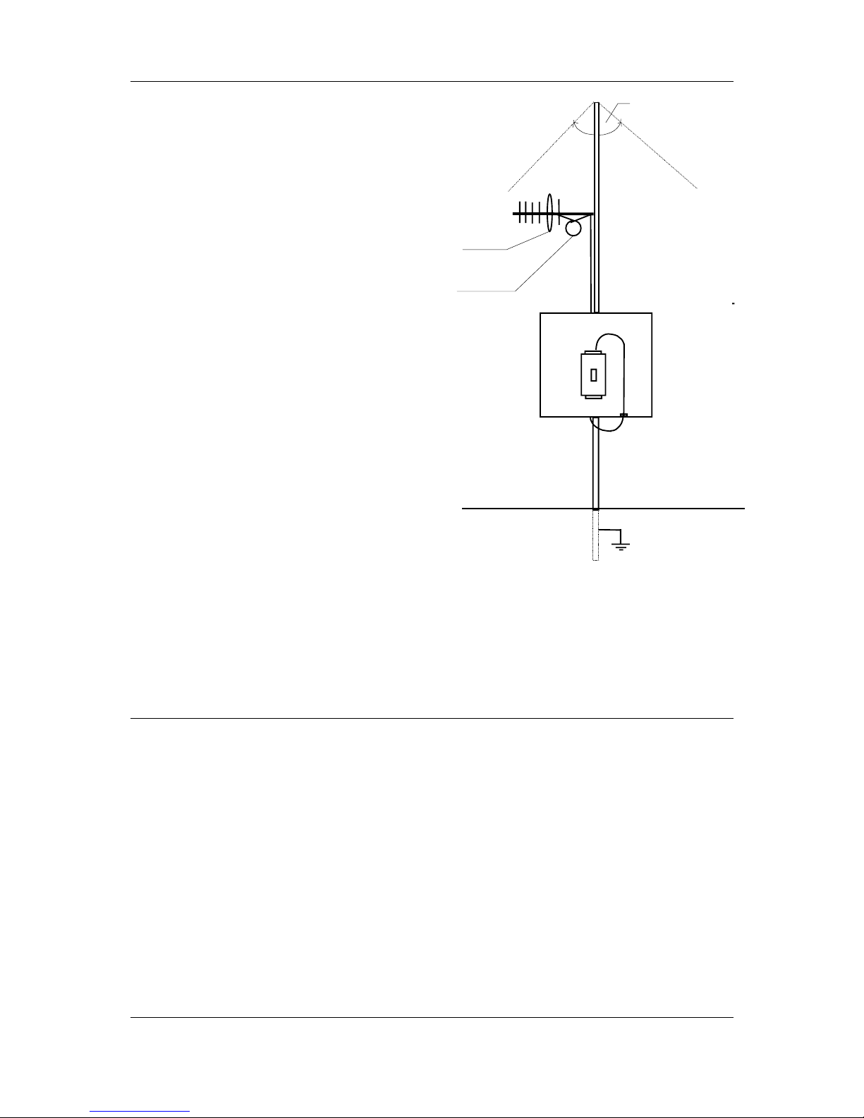
Where antennas are mounted on elevated masts, the masts should be effectively earthed to
avoid lightning surges. For high lightning risk areas, surge suppression devices between the
module and the antenna are recommended. If the antenna is not already shielded from
lightning strike by an adjacent earthed structure, a lightning rod should be installed above the
antenna to provide shielding.
3.2.1 Dipole and Collinear antennas.
A collinear antenna transmits the same amount of radio power in all directions - it is easy to
install and use. The dipole antenna with integral 15 ft (5m) cable does not require any
additional coaxial cable, however the other collinear antennas do not have integral cable and
an external cable length must be connected - such as the CC10 or CC20 cable kits..
Collinear and dipole antennas should be mounted vertically, preferably no less than 2 ft (0.6
metre) away from a wall or mast to obtain maximum range. The CFD890 dipole antenna is
the preferred antenna for use in industrial plants and factories.
3.2.2 Yagi antennas.
A Yagi antenna provides high gain in the forward direction, but lower gain in other
directions. This may be used to compensate for coaxial cable loss for installations with
marginal radio path.
1m minimum
COLINEAR
ANTENNA
MAST
EARTH STAKE
IF GROUND CONDITIONS ARE
POOR, INSTALL MORE THAN
INSTALL AE R IAL ABO V E
LOCAL OBSTRUCTIONS
ANT
905U
SURGE
ARRESTOR
(OPTIONAL)
COAXIAL CABLE
WEATHERPROOF
CONNECTORS WITH
“3M 23” TAPE
STRESS RELIEF LOOP
PROVIDE GOOD
GROUND
CONNECTION TO
MAST, MODULE
AND SURGE
ARRESTOR
GND
for best performance
Chapter Three Installation
MAN_905G_1.16 Page 30
The Yagi gain also acts on the
receiver, so adding Yagi
antennas at both ends of a link
provides a double
improvement.
Yagi antennas are directional.
That is, they have positive gain
to the front of the antenna, but
negative gain in other
directions. Hence Yagi
antennas should be installed
with the central beam
horizontal and must be pointed
exactly in the direction of
transmission to benefit from
the gain of the antenna. The
Yagi antennas may be installed
with the elements in a vertical
plane (vertically polarized) or
in a horizontal plane
(horizontally polarized). For a
two station installation, with
both modules using Yagi
antennas, horizontal
polarization is recommended.
If there are more than two stations transmitting to a common station, then the Yagi antennas
should have vertical polarization, and the common (or “central” station should have a
collinear (non-directional) antenna.
Also note that Yagi antennas normally have a drain hole on the folded element - the drain
hole should be located on the bottom of the installed antenna.
3.3 Power Supply
The 105G power supply is a switch-mode design which will accept either AC or DC supply.
The module includes an integral battery charger for a backup battery.
The module accepts supply voltages in the following ranges :
12 – 24 volts AC RMS or 9 – 30 volts DC at the “supply” terminals, or
10.8 –15 volts DC at the “battery” terminals.
The power supply should be rated at 1.5 Amps and be CSA Certified Class 2. For use in
Class 1 Div 2 explosive areas (USA/Canada), the power supply must be approved for Class 1
Div 2 use.
905U
A
ntenna installe d
with drain holes
down
Coax feed looped
at connection
90
o
905U-G Wireless Gateway User Manual
Page 31 ©September 2004
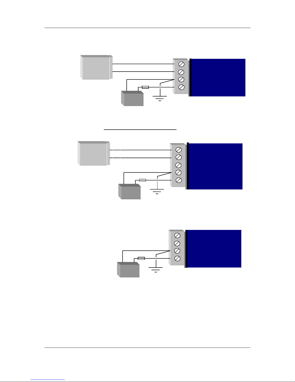
3.3.1 AC Supply
The AC supply is connected to the “SUP1” and “SUP2” terminals as shown below. The AC
supply should be “floating” relative to earth.
3.3.2 DC Supply
For DC supplies, the positive lead is connected to “SUP1” and the negative to “GND”. The
positive side of the supply must not be connected to earth. The DC supply may be a
floating supply or negatively grounded.
The module may also be powered from an external 11 – 15 VDC battery supply without the
need for a “normal” supply connected to “SUP1”. This external battery supply is connected
to “BAT+” and “GND” terminals. The positive lead of the external supply should be
protected by a 5A fuse.
Upon failure of the normal supply, the module may continue to operate for several hours
from a backup battery. The battery charger is designed for sealed or vented lead acid batteries
between 5 and 24 amphours - other types of batteries should not be used. Typically, a 5
Ahr battery will supply the 105G for 1 – 2 days, depending on the type of 105G.
SUP1
SUP2
GND
BAT+
12 – 24 VAC
Power
Supply
AC Out
- +
105U-G
Optional Battery
Fuse 5A
GND
SUP1
SUP2
GND
BAT+
9 – 30 VDC
Power
Supply
DC Out
- +
105U-G
Optional Battery
Fuse 5A
_
+
SUP1
SUP2
GND
BAT+
- +
105U-G
BATTERY SUPPLY
11-15 VDC
Fuse 5A

Chapter Three Installation
MAN_905G_1.16 Page 32
On return of normal supply, the unit will recharge the battery. The maximum output of the
battery charger is 0.7A when the supply voltage is greater than 12V, and 0.3A for less than
12V.
The 105G monitors the power supply and provides the following internal values, which can
be mapped as I/O values:
• Power failure (I/O Reg 4309) - if the supply voltage drops below 8V, this status value is
set on, and set off again when the voltage is more than 9V. For AC Supplies, this
indicates low voltage at approximately 10 VAC, and the status is cleared when the supply
voltage rises above approximately 12VAC
• Low battery voltage (I/O Reg 4308) - this status value is set on if the battery voltage
drops to 11.3, and resets off when the battery voltage is more than 11.8V.
• Battery voltage value (I/O Reg 4310) - 8 – 40VDC corresponds to hex 4000 – hex C000.
• Supply voltage (I/O Reg 4311) - 8 – 40VDC corresponds to hex 4000 – hex C000.
3.3.3 Solar Supply
A 105G can be powered from a solar supply using an external regulator. If a 12V solar
supply is used, the 12V battery can be connected to the battery supply connections of the
105G and the 105G will monitor for low battery status and also battery voltage. If a 24V
solar supply is used, the 24V battery should be connected as a DC supply (SUP1 and GND) the supply voltage can be monitored however the “supply fail” voltage will activate too low
to be used as a battery fail status.
3.4 Input / Output
The 105G has eight on-board discrete/digital I/O. These act as both discrete inputs and
discrete outputs.
3.4.1 Digital Inputs / Outputs
All eight of the 105G DIO terminals may be used as discrete inputs. These inputs are
suitable for voltage free contacts (such as mechanical switches) or NPN transistor devices
(such as electronic proximity switches). PNP transistor devices are not suitable. Contact
wetting current of approximately 5mA is provided to maintain reliable operation of driving
relays.
Each digital input is connected between the appropriate “DIO” terminal and common
“COM”. Each digital input circuit includes a LED indicator which is lit when the digital input
is active, that is, when the input circuit is closed. Provided the resistance of the switching
device is less than 200 ohms, the device will be able to activate the digital input.
+
_
DIO
DIO
GND
105U-G
Voltage-free
contact in
p
ut
Transisto
r
input
V+
V
-

905U-G Wireless Gateway User Manual
Page 33 ©September 2004
All eight of the 105G DIO terminals may also be used as discrete outputs. The digital
outputs are transistor switched DC signals, FET output to common rated at 30VDC 500 mA.
Digital outputs may be configured to individually turn off if no command message is
received to that output for a certain period. This feature provides an intelligent watch dog for
each output, so that a communications failure at a transmitting site causes the output to revert
to a known state. See Chapter 4 Configuration for further details.
The output circuit is connected to the appropriate “DIO” terminal. Each digital output circuit
includes a LED indicator which is lit when the digital output is active.
3.5 Serial Port
3.5.1 RS232 Serial Port
The serial port is a 9 pin DB9 female and provides for connection to a terminal or to a PC for
configuration, field testing and for factory testing. It is also used by the Modbus/DF1 version
for fieldbus connection.
This port is internally shared with the RS485 - ensure that the RS485 is disconnected before
attempting to use the RS232 port. Communication is via standard RS232 signals. The 905G
is configured as DCE equipment with the pinout detailed below.
DB9 Connector Pinout:
Pin Name Direction Function
1DCD Out
Used for "active" signal.
2 RD Out Serial Data Output
3 TD In Serial Data Input
4DTR In
Data Terminal Ready - may be used by Host Protocol
Driver
5 SG Signal Ground
6 DSR Out Data Set Ready - always high when unit is powered on.
7 RTS In Request to Send - may be used by Host Protocol Driver
8 CTS Out Clear to send - may be used by Host Protocol Driver
9 RI Ring indicate - not connected
_
+
DC
Load
Max 30VDC
0.5A
DIO
DIO
GND
105U-G

Chapter Three Installation
MAN_905G_1.16 Page 34
Hardware handshaking using the CTS/RTS lines is provided, and are under the control of the
Host Comms Driver. Example cable drawings for connection to a DTE host (a PC) or another
DCE host are detailed below:
905U-G
DB9
905U-G
DB9
3.5.2 RS485 Serial Port
RS485 should not be used with the DF1 unit. The RS485 port provides for communication
between the 905G unit and its host device using a multi-drop cable. Up to 32 devices may be
connected in each multi-drop network. Note that the RS485 port is shared internally with the
RS232 port - make sure that the RS232 port is disconnected before using the RS485 port.
RS485 is a balanced, differential standard but it is recommended that shielded, twisted pair
cable be used to interconnect modules to reduce potential RFI. An RS485 network should be
wired as indicated in the diagram below and terminated at each end of the network with a
120-ohm resistor. On-board 120 ohm resistors are provided and may be engaged by operating
the single DIP switch in the end plate next to the RS485 terminals. The DIP switch should be
in the “1” or “on” position to connect the resistor. If the module is not at one end of the
RS485 cable, the switch should be off.
905U-G
INTERNAL
EXTERNAL RESISTOR
REQUIRED
TERMINATING
RESISTOR SWITCH
ON = TERMINATION
OFF = NO TERM.
RESISTOR

905U-G Wireless Gateway User Manual
Page 35 ©September 2004
It is important to maintain the polarity of the two RS485 wires. On the 905G, terminal A
(the terminal on the right) is positive and terminal B is negative.

Chapter Three Installation
MAN_905G_1.16 Page 36
3.6 Profibus Port
The Profibus RS485 connector is a D9 connector in the top end-plate of the module (see
below).
905U-G-PR1 (Profibus Slave) End Plate:
Note: If the “Use Rotary Switch Address” option in configuration software is selected, the
two rotary switches are used to specify the Profibus Node Address in the range 0 – 99. In this
case, the value on the left switch is multiplied by 10 and added to the value on the right
switch to give the node address.
Where the 905G module is mounted at the end of the RS485 link, the RS485 link should be
terminated by switching the termination switch “on” (down in the above diagram).
905U-G-PR2 (Profibus Master) End Plate:
For the Profibus Master 905G a second, unused, connector is also present.
The Profibus RS485 connection should be made to pins 3 and 8 of the Profibus D9 connector.
The pinouts for this connector are:
ANTENNA
CONNECTION
PROFIBUS D9
CONNECTOR
SELECTOR
SWITCHES
DIAGNOSTIC
LED’s
CONFIGURATION
ENABLE
RS485
TERMINATION
SWITCH
ANTENNA
CONNECTION
PROFIBUS D9
CONNECTOR
DIAGNOSTIC
LED’s
CONFIGURATION
ENABLE
UNUSED D9
CONNECTOR

905U-G Wireless Gateway User Manual
Page 37 ©September 2004
Pin Description
1 Not connected
2 Not connected
3 +ve RS485 (Positive)
4 RTS (request to send)
5 GND - Isolated GND from RS485 side
6 +5V - Isolated 5V from RS485 side
7 Not connected
8
-ve RS485 (Negative)
9 Not connected
3.7 Ethernet Port
For 905U-G-ET1 modules only.
The Ethernet connection uses a standard RJ45 connector on the top end-plate of the module.
The selector switches should all be “off” (in the diagram below, “off” is up).
ANTENNA
CONNECTION
RJ45 ETHERNET
CONNECTION
SELECTOR
SWITCHES
DIAGNOSTIC
LED’s
CONFIGURATION
ENABLE

Chapter Three Installation
MAN_905G_1.16 Page 38
3.8 Modbus Plus Port
For 905U-G-M+1 modules only.
Connection to the Modbus Plus Network is via the 9-pin D-SUB connector located at the
antenna end of the module. Pin-outs are outlined in the table below.
See section on configuration for description of selector switches.
Modbus Plus 9-pin D-SUB Connector:
Pin Name
1 Cable Shielding
2 MBP Line B
3 MBP Line A
Housing PE
ANTENNA
CONNECTION
D9 MODBUS
PLUS
SELECTOR
SWITCHES
DIAGNOSTIC
LED’s
CONFIGURATION
ENABLE

905U-G Wireless Gateway User Manual
Page 39 ©September 2004
3.9 DeviceNet Port
For 905U-G-DE1 modules only.
Connection to the DeviceNet Network is via the 5-pin plugable screw terminal connector
located at the antenna end of the module. Pin-outs are specified below.
5-pin plugable screw terminal fieldbus connector:
Pin Signal Description
1 V- Negative Supply Voltage
2 CAN_L CAN_L bus line
3 SHIELD Cable shield
4 CAN_H CAN_H bus line
5 V+ Positive supply voltage
DeviceNet uses termination resistors at each physical end of the bus. The termination resistor
should be 121 ohm. This should be connected between CAN_H and CAN_L on the bus.
ANTENNA
CONNECTION
DEVICENET
CONNECTION
SELECTOR
SWITCHES
DIAGNOSTIC
LED’s
CONFIGURATION
ENABLE

905U-G Wireless Gateway User Manual
Page 41 ©September 2004
Chapter 4 CONFIGURATION
4.1 Introduction
A Windows program is provided to configure the 905U system. The configuration is done on
a system basis - referred to as a “project” in the program. After the system configuration is
entered, the configuration file can be loaded into each module via the RS232 port.
Each Project is configured with:
• a system address, which is common to every module in the same system, and is used to
prevent "cross-talk" between modules in different systems. Separate networks with
different system addresses may operate independently in the same area without affecting
each other. The system address may be any number between 1 and 32 767. The actual
value of the system address is not important, provided all modules in the same system
have the same system address value. A system address of zero should not be used.
The configuration program automatically offers a random number for the system address
- you can change this to any number in the valid range but we recommend that you use
the random number.
• a password for access protection. This is an optional feature. If selected, the project file
can only be opened by entering the correct password.
• a security encryption key, used to encrypt and decrypt radio messages. This is an
optional feature. If selected, the configuration program will offer a random security key,
or this can be over-written with your own key. A key is a string of any 8 ASCII
characters.
Each module in the project is configured with a unit address. Each module must have a
unique unit address within the one system. A valid unit address for a 905G is 1 to 95. A
network may have up to 95 addresses communicating directly via radio (unit addresses 1 to
95). 905U I/O modules can have up to 31 modules communicating via RS485 (unit addresses
96 to 127).
The configuration program may allocate more than one unit address to a 905G if it is required
because of the size of the system. If this is necessary, it will be done automatically by the
configuration software.
Configuration consists of:
1. selecting the types of modules in the system and selecting address values
2. linking (called “mapping”) I/O registers to remote I/O
3. setting operating parameters such as change sensitivities and update times
4. selecting “block mappings” - only for block transfer of I/O registers between 905G
modules
5. selecting fieldbus addressing, and serial port configuration (Modbus & DF1 only)
6. linking Radio Interface registers to Fieldbus Interface registers (All modules except
MD1)
All of these steps must be performed to configure the 905G module.

Chapter 4 Configuration
MAN_905G_1.16 Page 42
4.2 Configuration Program
The configuration software is available on a CD, and needs to be installed on your PC before
you can use it. The CD contains a setup file called setup.exe. Select the configuration
software window on the Product CD and an installation Wizard will guide you through the
installation procedure. To upload and download configuration files to a module, you will
need a RS-232 serial cable as shown below.
1 1
2 2
3 3
4 4
5 5
6 6
7 7
8 8
9 9
4.2.1 Program Operation
Start the software by either
clicking on the start bar and
navigating to the
Configuration menu or by
running ESERIES.EXE in
the directory selected in the
setup stage.
The Initial screen will
appear.
From the initial screen, , you
can select an existing
project, or start a new
project. The name of the
project will create a new
folder which will eventually
contain the configuration
files for the modules in this
system. Project folders are located under
the folder \Projects\ - for example, if
you create a project called “Fire Pumps”,
then the files for this project will be
found in the folder c:\……\Projects\Fire
Pumps\.
When you have selected the project, a
Required
Optional
905G PC
DB9 Male DB9 Female

905U-G Wireless Gateway User Manual
Page 43 ©September 2004
screen will appear where you may enter the system address.
If you are editing an existing project, the system address will already have been entered. Do
not change the system address
unless you are going to reprogram all of the modules in
the system.
Password. You have the
option of entering a password to
protect the configuration files
against unauthorized changes.
When you open a new project,
you will be asked to enter a
password - if you do not enter
any text - that is, press “ESC”
or “Enter”, then password
protection is disabled. If you do
enter a password, then you will
need to enter this password to
access the project. Without the
password, you are unable access
the project
The password can be between 6
and 256 characters. You can
also change password at any
time by over-typing the
passowrd.
If you are starting a new project, you have the option of “Enabling Security”. This option
enables encryption of
the data sent over the
radio. - please read
Section 4.2.2 and the
associated warnings
before using this
option.
To proceed with the
configuration, doubleclick on the project
name on the menu on
the left side of the
screen. “Units” will
appear. You can now
enter the types of units
which will be used in
the system. If you double-click on “Units”or select the “+” sign beside “Units”, then the
modules that have already been created will be displayed.
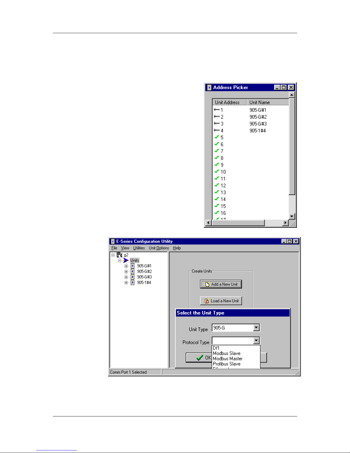
Chapter 4 Configuration
MAN_905G_1.16 Page 44
Loading configuration from an existing module
To load the configuration from a module, connect the module to the PC via the RS232 cable,
put the module into “Configuration Mode” by pressing the configuration button on the top
end-plate, and click on “Load Unit”. This will allow you to view the module configuration,
change it, or copy it for another module - refer to section 4.10 for full details.
Adding a new module to the system configuration
To add a new module to the system configuration, click
on “Units” on the left-hand menu and then “Add Unit”.
Select the type of module from the list. For 905G
modules, you will be asked to select the bus protocol.
This must match the 905U-G module type you have
installed.
You have the option of selecting a unit address for the
module, or allowing the program to select one
automatically. If you choose to select the unit address
the program will display the list of available addresses
for you to select - valid addresses are 1 – 95.
The default name for a unit will include the unit
address. For example, “905-G#10” is a 905U-G
module with unit address 10. You can change the name
of a unit - for example, you could replace the default
name with “Pump Station 14”.
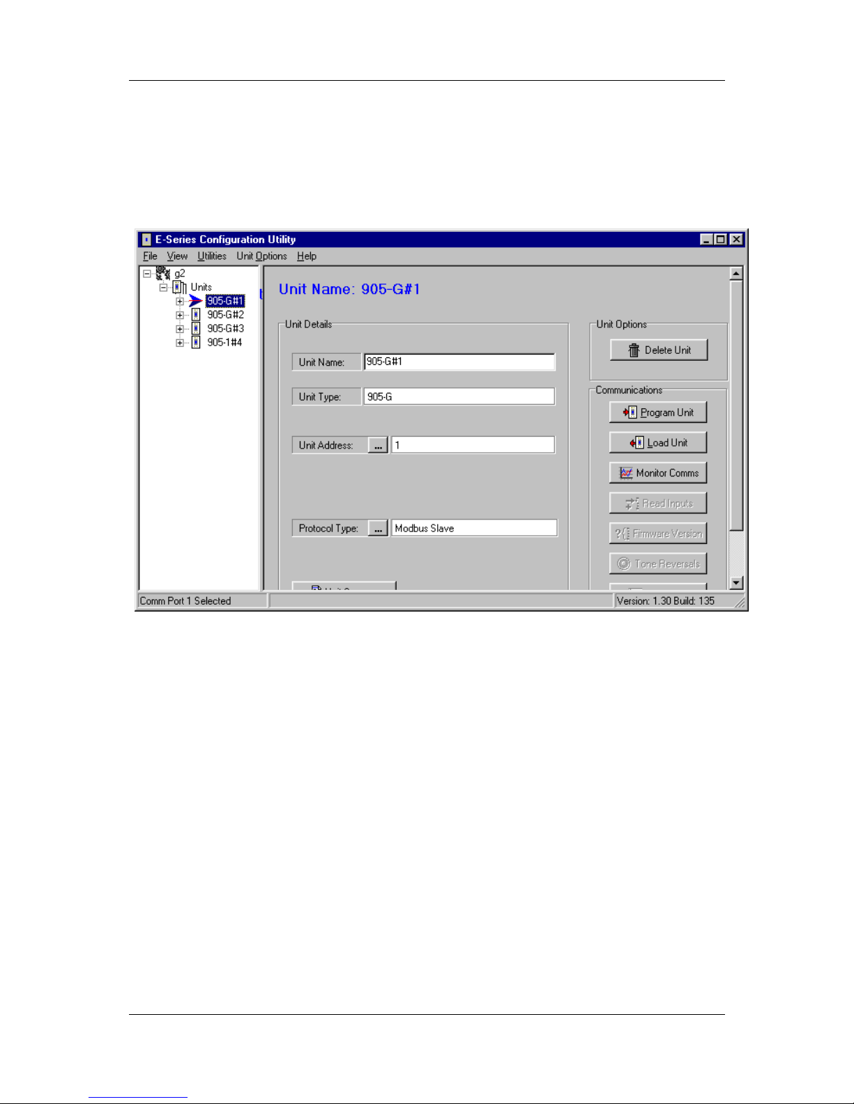
905U-G Wireless Gateway User Manual
Page 45 ©September 2004
Deleting a Unit
A module can be deleted from the configuration by highlighting the unit and selecting
“Delete Unit”.

Chapter 4 Configuration
MAN_905G_1.16 Page 46
4.2.2 Security
There are two security features available. You can enter a password to protect the
configuration files, and you can enable security encryption of the radio transmissions.
The password can be between 6 and 256 characters. The password is case sensitive and any
ASCII characters can be used. If you have entered a password, then this password will need
to be entered whenever the configuration is changed. You are able to change the password
from the “Utilities” menu. If unauthorized access to the files is a concern, we recommend
that you change the password regularly or whenever there is a change of staff.
Data Encryption is an additional level of security. The security option uses a 64 bit security
key to provide data encryption of the radio messages. All modules in the same system will
be configured with the same security key used to encrypt and decrypt the messages. This
feature is available for modules with firmware version 2.1 and higher. If you are adding
modules to an old system which does not have the security encryption feature, then you
cannot use security encryption on the new modules.
Note that the security key is different than the password.
• To enable the security encryption, select the “Enable Security” box on the project display.
An 8-character random security key is automatically generated. If desired, a different
security key may be entered and you will be prompted to enter the security code a second
time to confirm. The security key can be any characters or numbers. Characters are case
sensitive. The security key will never be displayed.
• If you do not enable security, there will be no data encryption of the radio messages.
This is the default setting.
• If a security key has been entered, this key is downloaded into each module as part of the
configuration download process. You can download another configuration at any time if the security key is different, or if there is no security key in the new configuration, the
old key will be over-written.
• You can change the security key in the configuration files simply by entering a new
security key in the security key window. You will be prompted to confirm the new
security key. Note that if you change the security key, it will not match the security key
previously loaded into existing modules.
• If you want to change a configuration, we recommend that you change the archived
configuration, and then download the configuration onto the module. The archived
configuration already has the valid security key.
• If you lose the archived configuration, you can upload the configuration from a module,
but you cannot upload a security key. That is, you can upload the module configuration,
view it, change it - but if you don’t know the original security key, the old key will be
over-written when you download the new configuration. This module will no longer
communicate with other modules in the system as the security key is different.
The security options provide security against a “hacker” in the following way:
A hacker cannot listen-in to radio messages without the security key to decrypt the radio
messages. Similarly, a hacker cannot force outputs by transmitting a radio message to a
module without the security key.
A hacker cannot access the security key from an installed module or from the
configuration files.

905U-G Wireless Gateway User Manual
Page 47 ©September 2004
The archived configuration files cannot be changed, downloaded or uploaded without the
password.
Warning!!
These security options provide a high level of security, but no data-security system can
provide “100% protection”. But it does make it very difficult for someone to interfere
with the 905U system - difficult to the point where there would be many easier
alternate ways to cause malicious damage.
The password must be kept in a secure place. Security procedures need to be adopted.
If staff with access to the password leave your organization, we recommend that the
password be changed.
We recommend that you use a random 8-character string for the security key and that
you do not record the key. It is not necessary to know what the security key is. The key
will be recorded in the archived configuration files, and therefore the configuration files
should be held in a secure place and backed up.
The security key does not prevent a hacker uploading a configuration from a module
and downloading with a new security key. This module will no longer operate with
other modules in the system. To prevent this, unauthorized access to modules must be
prevented.
If you lose the configuration files, you can regenerate these by uploading the configuration
from every module in the system into a new project with a new security key. After uploading
each module, download the configuration with the new security key.
If you wish to change the security key, simply enter a new key in the configuration program,
and download the new configuration to all modules in the system.
Note on Ethernet 905U-G. You are able to access the module configuration of an Ethernet
905G via the Ethernet port. To prevent this access, do not select “Enable Ethernet Debug” on
the Ethernet configuration display - see section 4.8.

Chapter 4 Configuration
MAN_905G_1.16 Page 48
4.3 Mappings 905G to 905U I/O Modules
To transfer remote input signals to a 905G, or transfer a value to a remote output from a
905G, you set up “I/O mappings”. You enter mappings into the source unit, not the
destination unit. That is, you configure a mapping at the “input” module. If you want to
transfer an input signal at a 905U module to a 905G register, you enter a mapping at the
905U I/O module. If you want to transfer a 905G register to an output signal at a 905U
module, you enter a mapping at the 905G module.
To configure mappings, double-click on the module in the left-hand menu - the menu will
expand with selections for that module. Select “Mappings”.
Each mapping comprises only one I/O point.
“Block Mappings” provide more advanced
communications between 905G modules.
4.3.1 Mappings from Inputs at Remote 905U I/O Modules
Refer to the 905U I/O User Manual.
When mapping inputs to a 905G, you will be asked to select an I/O Register. Select the “…”
box beside the “At I/O Register” heading - this will allow you to select the I/O register
between 0 and 4299.

905U-G Wireless Gateway User Manual
Page 49 ©September 2004
Any I/O registers that have already been selected will have a color shading.
The update times, analog sensitivities for these mappings can be set as per normal I/O
mappings.
To map several inputs to consecutive I/O registers, use “Shift”-select or “Ctrl” - select to
highlight the inputs, and select the first I/O register in the range. The selected mappings will
be entered with consecutive I/O registers.
For each “remote input” configured to a 905G, there is a comms-fail time parameter in the
905G. If the 905G does not receive a message destined to that I/O register within the
“comms fail” time, then the “comms fail” status for that I/O register will be set - the most
significant bit of the status register will be set to 1. The comms fail time should be more
than the corresponding update time at the remote input.

Chapter 4 Configuration
MAN_905G_1.16 Page 50
To set the
comms fail
times, select
the 905G, and
select the
“Comms Fail
Time” option.
Each remote
input already
mapped to the
905G will
automatically
be listed,
including the
remote module
containing the mapping.
The default value for the comms-fail time is “disabled” or zero. To enter a time, select the
I/O register from the list. The comms-fail time should be greater than the update time of the
remote input.
4.3.2 Mappings from 905G to Outputs at Remote 905U I/O Modules
Mappings can be entered in the 905G to remote outputs. Select the “Mappings” option under
the 905G. Select an I/O register and select the remote module and the output channel.
To map several consecutive I/O registers to several outputs, select the first I/O register in the
range and use “Shift”-select or “Ctrl” - select to highlight the multiple outputs. The selected
mappings will be entered with consecutive I/O registers.
Change Sensitivities
Radio messages to remote modules can be change messages (when the value of the I/O
register changes) or update messages (when the update time has elapsed). If a change
message is sent, the update period restarts.

905U-G Wireless Gateway User Manual
Page 51 ©September 2004
You can configure the amount of change required to trigger a change message - this is
called the change sensitivity. Sensitivities are configured for blocks of I/O registers - that
is, each I/O register does not have a unique sensitivity. You can configure up to 50
sensitivity values - that is, there can be 50 blocks of registers with different sensitivities.
For more information on this, refer to section 4.5.

Chapter 4 Configuration
MAN_905G_1.16 Page 52
Update Times
To change the
update times of
output
mappings,
select the
Update Times
option. Any
I/O registers
that have
already been
mapped to
remote outputs
will
automatically
be listed. The default update time is 10 minutes.
Changing Multiple Settings
You can change the Comms Fail Times or Update Times of several I/O points simultaneously
by using the <Shift> Select feature. For example, if you want to change all times to 1
minute, you could change each individually, or you could “block” all entries using the “Shift”
Select feature and select “Edit”. You only need to enter the change once to change all of the
inputs selected. This feature is also available with the other configurable parameters.
4.3.3 Don’t Send if in Comm Fail
You can configure a special “Don’t Send if in Comms Fail” mapping. If this is configured
for a particular remote module, the 905G will not transmit output messages to this remote
address, if there is a communications failure status on any input or output configured for the
same remote address. Output messages will re-start when a message is received from the
remote module. The use of this option can prevent the radio channel becoming congested if
there are many outputs at that module.

905U-G Wireless Gateway User Manual
Page 53 ©September 2004
To configure this special mapping, select the “New Don’t Send in Comms Fail Mapping”
box. You will be asked to select which remote module this function applies to. You can
enter more than one of these mappings if there are more than one modules.
4.3.4 Startup Polls
You can enter start up polls for remote modules by using the “New Poll Mapping” box. This
function is the same as for the 905U I/O modules. A start-up poll is a special message sent
when the 905G starts up. When the remote module receives a start-up poll, it will
immediately respond with update messages for all its inputs that are mapped to the 905G.
This allows the 905G to have correct values on start-up.
4.3.5 Polls to Remote Modules
It is possible for a 905G to send a poll to a remote module at other times apart from start-up.
A poll can be sent under the following events:
• based on a configurable time period
• based on real time clock
• on-demand by the host device.
For information on this configuration, refer to the next section on “Block Mappings”.
4.4 Mappings from 905G to other 905G Modules
Individual links between 905G modules can be configured under the “Mappings” selection as
described in the previous section. For example, if you want to transfer I/O Reg 144 in
905G#2 to I/O Reg 286 in 905G#3, you can enter the following mapping:
Whenever I/O Reg 144 changed by the sensitivity amount, 905G#2 would send a message to
905G#3 to write the value in I/O Reg 286. The problem arises if there are a lot of these
mappings. Each radio message only relates to one register-register link. If you want to map
1000 registers from one 905G to another, then this could generate a lot of radio messages.
To get around this problem, it is possible to configure “block mappings”. With a block
mapping, multiple registers (a “block of registers”) can be transferred together in the one
radio message. This improves the efficiency of the radio communications.

Chapter 4 Configuration
MAN_905G_1.16 Page 54
Read/Write Mappings
The mappings can be “read” or “write” mappings. A Read mapping is a request sent to
another 905G to return a block of values. A Write mapping is a message sending a block of
values to another 905G. A Read mapping from 905G#2 to 905G#3 could be the same as a
Write mapping from 905G#3 to 905G#2 (that is, in the reverse direction) - except the Read
mapping is initiated from #2 and the Write mapping is initiated from #3.
Word/Bit Mappings
Read and Write mappings are also selected as Word or Bit mappings - that is, you can select
a Read Word mapping or a Read Bit mapping and you can select a Write Word mapping or a
Write Bit mapping. “Word” refers to a complete 16-bit register value; “Bit” refers to the
value of the most significant bit of a register - this bit is the “binary value” or “digital value”
of the register.
If you use a Word block mapping of 50 registers, you are transferring a block of 50 x 16-bit
values. If you use a Bit block mapping of 50 registers, you are only transferring the digital
value of each register - that is 50 x 1 bit values. This is a lot more efficient for a radio
message, but bit mappings are only suitable for discrete or digital I/O. A Bit mapping will
convert the 16-bit register to a single bit, transfer it and store the bit value in the most
significant bit of the destination register.
Note: The maximum block size for each block mapping is 64 registers.
REMOTE
905G
BLOCK OF I/O
REGISTERS
ACKNOWLEDGMENT
BLOCK WRITE
MESSAGE
BLOCK OF I/O
REGISTERS
READ REQUEST
BLOCK READ
MESSAGE
LOCAL
905G

905U-G Wireless Gateway User Manual
Page 55 ©September 2004
4.4.1 Entering a Block Mapping
Select the “source” 905G on the left hand menu - select “Block Mappings” and then “New
Block Mapping” from the right-hand display. The Block Mapping Configuration display will
appear.
Select the “Command Type” from the pop-down window in the centre of the display. The
red arrow will confirm the direction of the block transfer. Now select the destination module
- only the 905G modules already configured will be shown. If you need to use repeaters in
the radio link, enter the repeater addresses, starting with the repeater closest to the source
module.
Under “Source Gateway”, enter the I/O Register and I/O Count. The I/O Register is the first
register in the block and the I/O Count is the number of registers - in the above example, the
block of registers will be 110 – 124 (15 registers starting at I/O Reg 110).
If you are entering a Write mapping, then the values in this block will be sent to another
905G. If it is a Read mapping, then values from another 905G will be sent to this block.
Under “Destination Gateway”, enter the I/O Register - this is the first register in the block.
You do not need to enter the block size as this will always be the same as the block size in
the source 905G. In the above example, the destination block will be I/O registers 32 – 46
(15 registers starting at register 32). So, in the above example, a block of 15 x 16-bit values
will be written from I/O Reg 110 – 124 in 905G#1 to I/O Reg 32 – 46 in 905G#2.
Each mapping entered is allocated a status register - the register number appears on the right
hand of the Block Mapping display. These registers store relevant status information about
the block mapping - the structure of the Block Mapping status registers is shown in
Appendix 1.

Chapter 4 Configuration
MAN_905G_1.16 Page 56
In the above example, the status register for the block mapping has been automatically
assigned to register 9500.
The rest of the mapping configuration involves the mapping trigger - or what initiates the
mapping message.
Mapping “Triggers”
A block mapping can be “triggered” or initiated by several different methods.
• By the host device writing to a “trigger register” in the source 905G - the block mapping
message is sent each time the host device writes to the trigger register.
• By configuring a time period - the 905G will send the block mapping message if this
time period has elapsed since the last message has been sent.
• By configuring a real-time clock - the 905G will send the block mapping message at the
configured times.
• By a change-of-state within the I/O block. This can only occur for Write mappings. If a
value in the block changes by more than the sensitivity amount, then the block message
will be sent. You can enter a delay period such that the message is sent after the delay
period.
Combinations of the above triggers can occur - for example, the block mapping message
will be sent if a change-of-state occurs, AND at the configured real-time, AND when the host
device writes to the trigger register.
4.4.2 Host Device Trigger
Each block mapping that is configured is allocated a status register in the range 9500 – 9999
(i.e. one status register for a maximum of 500 possible block mappings). The status register
for a given block mapping is shown on the right hand side of the Block Mapping display
(under the heading “Status Lcn”). Bit 13 of the associated status register is the “Force bit” - if
Bit 13 is turned “on”, then the associated mapping is forced, or triggered. Depending on the
module version, a particular algorithm may apply to the setting of the force bit. This
algorithm and details of the block status registers are given in Appendix 1.

905U-G Wireless Gateway User Manual
Page 57 ©September 2004
4.4.3 Time Period
On the Block Mapping display, there are two configuration windows - “Period” and
“Offset” - these determine the time period trigger and real-time trigger.
For a time-period trigger, select “Continuous” in the “Period” pop-down window. Under
“Offset” enter the time-period in seconds. In the above example, the mapping will be sent
every 300 seconds or 5 minutes.
Note that the time period is after the last transmission - if the block mapping message is
triggered by the host device, or by a change-of-state, then the timer is reset and the time
period starts again.
The “Offset” value can be set from 0 – 4095 seconds (68 minutes). If you do not want the
message to be sent on a time period, set the “Offset” value to zero.
If you want the block mapping to be sent only on time period (and not on change as well),
select the “Disable” box in the bottom left hand corner - this disables change messages for
this block mapping.

Chapter 4 Configuration
MAN_905G_1.16 Page 58
4.4.4 Real-Time
The block mapping message can be sent at a real-time by setting the “Period” value. In this
example, “period” is set to 6 minutes - the message will be sent every 6 minutes starting at
the beginning of each hour. That is, the message will be sent at XX:00, XX:06, XX:12,
XX:18, XX:24 …. XX:54 - where XX represents any hour of the day.
If “Period” was set to 1 minute, then the message would be sent every minute, on the minute.
The “Offset” value provides an offset to the specified time. In this example, if the “Offset”
was set to 10 seconds, then the messages will be sent 10 seconds later - at XX:00:10,
XX:06:10, XX:12:10 etc.
The reason for the offset is to stagger messages with the same time setting. For example, if
you configure 5 block mappings all to be sent at 10 minutes, then the 905G will try to send
these messages at the same time - some of the messages will have to wait until the earlier
messages have been sent. If you are sending Read messages as well as Write messages, then
the return messages could clash with outgoing messages.
To avoid this, you can delay some messages using the Offset feature. For example, if you
have 5 mappings to be sent at 10 minutes, then the first could have zero offset, the second 3
sec offset, the third 6 sec offset etc.
If you do not wish to have a real-time trigger, set “Period” to continuous.
If you want the block mapping to be sent only on real-time (and not on change as well),
select the “Disable” box in the bottom left hand corner - this disables change messages for
this block mapping.
Setting the Clock
The clock within the 905G can be set by the host device, and read by the host device. The
905G provides four clock registers for days/hours/minutes/seconds - the registers are 4330 –

905U-G Wireless Gateway User Manual
Page 59 ©September 2004
4333. On power-up, these registers are set to zero. Reg 4333 increments each second, Reg
4332 increments each minute, Reg 4331 each hour and Reg 4330 each day.
The clock registers are used by the 905G for the real-time-clock trigger. The host device can
read these registers. The host device can also set the 905G clock at any time by writing to the
appropriate Set register. The Set registers are : 4340 – 4343. The procedure for setting the real
time clock via these registers depends on the module firmware version (to find out what
firmware version the module contains, simply display the diagnostics menu – see section on
diagnostics). The set registers can also be set via radio using appropriate I/O or block
mappings.
Item Clock Location Set Location
Days 4330 4340
Hours 4331 4341
Minutes 4332 4342
Seconds 4333 4343
Firmware versions up to 1.50:
Registers 4340 – 4343 are normally zero. When a value is written into one of these registers,
the 905G copies the value into the corresponding clock register, and then sets the Set register
back to zero. For example, if the host device writes a value of 7 into Reg 4341, the 905G will
write 7 into 4331 and set 4341 back to zero.
Firmware version 1.50 and later:
Registers 4340 – 4343 will only be transferred to the corresponding clock registers when
their value changes from 0. For example to write a value of 7 to the hours register, first write
the value 0 to the Set hours register 4341, then write the value 7 to the same register. (i.e. by
always first writing the value 0 to the Set register this ensures that the change-of-state from 0
will be detected). Values must be held (i.e. not change) for approx 200msec to be detected.
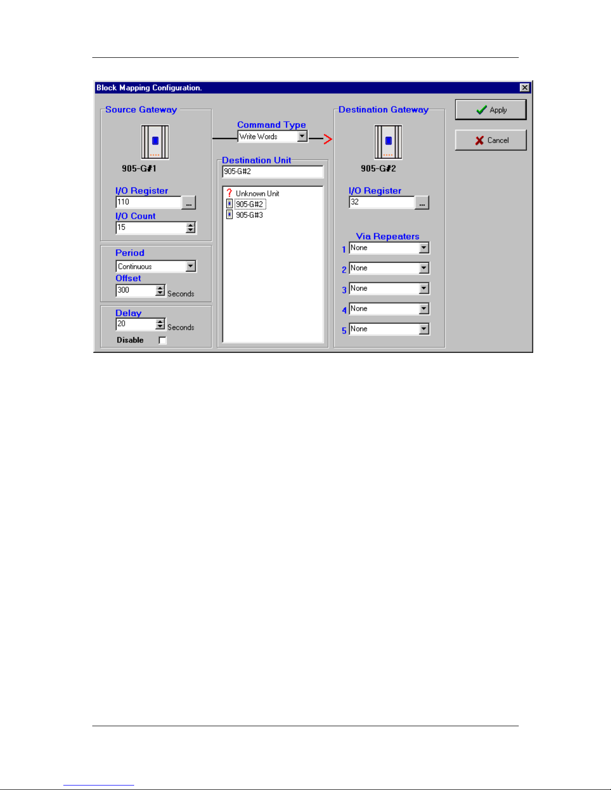
Chapter 4 Configuration
MAN_905G_1.16 Page 60
4.4.5 Change-of-State
If a value in the block changes by more than the sensitivity amount, then the block message
will be sent (this can only occur for Write mappings). The sensitivity values are set under the
“Sensitivity” option as per section 4.5.
A delay time can be entered to reduce the number of change triggers in active systems. For
example, if 20 seconds is selected in the “Delay” window, then the change message will be
sent 20 seconds after the change-of-state occurs - if other changes occur during the 20
second period, all of these changes are sent in the one message.
The delay time can be set from 0 – 254 seconds.
If you do not wish change messages to occur, select the “Disable” box.
4.4.6 Mixing Normal Mappings and Block Mappings
Block mappings can include I/O Registers already used with normal I/O mappings.
For example, a remote 905U I/O module could map a remote input to I/O Reg 743. At the
905G, the host device could read I/O Reg 743, and you could also configure a block mapping
including this register to another 905G. You could write a block I/O Reg 700 – 800 to
another 905G.
4.4.7 Comms Fail for Block Mappings
Each block mapping has an associated mapping number. Up to 500 block mappings may be
entered. A status register is maintained for each block mapping. The most significant bit of
this register contains the comm fail status.
If a block mapping does not receive an acknowledgement from the remote module, then the
comms fail status is set - this can be monitored by the host device.
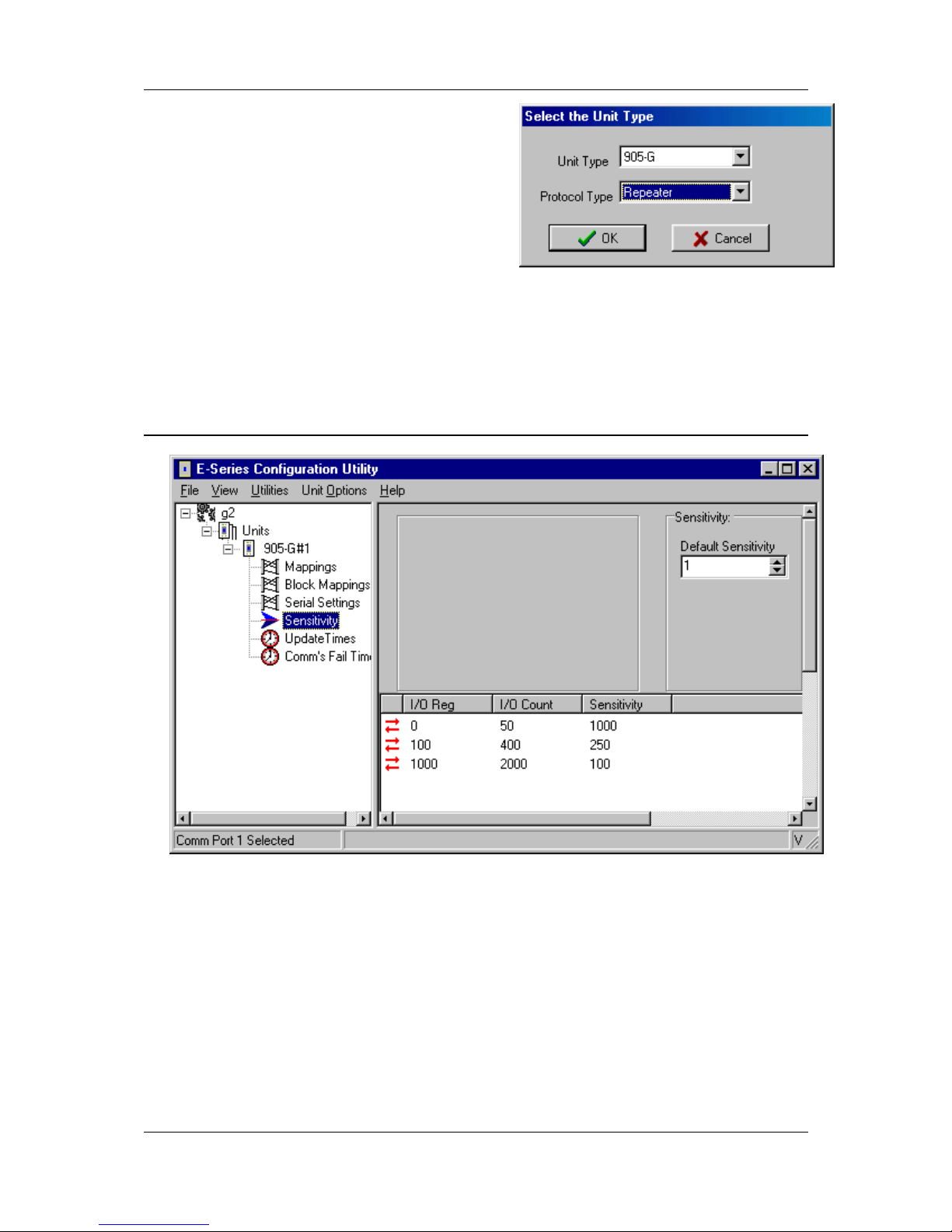
905U-G Wireless Gateway User Manual
Page 61 ©September 2004
4.4.8 “Repeater-only” Configuration
Any 905G module can act as a repeater unit.
However a 905G may need to be installed as a
repeater only (that is, there is no host device
connected). In this case, the base 905G, the 905UG-MD1 unit would normally be used as this is the
lowest cost of the 105G modules.
A repeater can be configured as a “Repeater-only”
unit. The advantages are:
the serial port will then provide on-line diagnostics (instead of off-line diagnostics), or
105S serial I/O modules can be connected to the serial port - normally 105S modules
cannot be used with MD1 units.
4.5 Change Sensitivity
“Change” messages for both individual I/O mappings and block mappings use a sensitivity
value to trigger the message. Sensitivities are configured for blocks of I/O registers - that is,
each I/O register does not have a unique sensitivity. You can configure up to 50 sensitivity
values - that is, there can be 50 blocks of registers with different sensitivities.
In the above example, three sensitivity blocks have been configured:
1. I/O registers 0 – 49 have a sensitivity of 1000 (or 1.5% of the 16 bit range)
2. I/O registers 100 – 499 have a sensitivity of 250 (or 0.4% of the 16 bit range)
3. I/O registers 1000 – 2999 have a sensitivity of 100 (or 0.15% of the 16 bit range)
All of the registers between 0 and 49 have a sensitivity value of 1000. If register 34 has
changed value by more than 1000 since the last transmission for that register, then a change

Chapter 4 Configuration
MAN_905G_1.16 Page 62
trigger will occur for register 34. Sensitivity values are in decimal and can vary between 1
and 65535 (16-bit).
Up to 50 blocks of sensitivities can be configured. If a register is included in more than one
block, then the first sensitivity value configured will be accepted and later values ignored.
Registers which are not included in any block use the “default” sensitivity which is also userconfigurable. In the above example, the default sensitivity is 1 and is the sensitivity for all
I/O registers not included in the three blocks.
Important Note. Sensitivity values need to be selected carefully for analog or counting
registers as small values can result in a large number of change messages, which can
overload the radio channel. A sensitivity value of 1 in 65535 is a change of 0.0015%. If the
host device writes an analog value to a 905G every 100msec, it will change by at least 1 bit
each time. A small sensitivity value will cause a change message to be sent every 100msec.
If there are many analog values in the same situation, then there would be many change
messages every 100msec. Sensitivity values for analog I/O should be set to be greater than
the normal process noise of the signal. For example, if a flow signal has a normal process
oscillation of 2.5%, then the sensitivity should be set to 3% (or a value of 2000) to avoid
change transmissions from the process oscillations.

905U-G Wireless Gateway User Manual
Page 63 ©September 2004
4.6 Serial Configuration - MODBUS
The 905U-G-MD1 module provides interface for Modbus Slave, Modbus Master and AllenBradley DF1. This Modbus interface uses the Modbus RTU protocol - also known as the
Modbus Binary protocol. This manual assumes that the reader has a good understanding of
the Modbus or DF1 protocol.
4.6.1 MODBUS Slave
If you use the 905G Modbus Slave interface, then the host device will be a Modbus Master
device. The only configuration required for the Modbus slave interface is selecting the
Modbus address and serial port parameters. This is done in the “Serial Settings” screen. A
valid Modbus slave address is 1 to 255.
Each I/O register (and status register) in the 905G can act as one of the following types of
Modbus registers
00001-09999 = Output Coils (digital/single bit)
10001-19999 = Input Bits (digital/single bit)
30001-39999 = Input Registers (analog/16 bit)
40001-49999 = Output Registers (analog/16 bit)
For example:
• If the Modbus Master sends the 905G a “read” command for Modbus input 10457, then
the 905G will respond with the value in I/O register 457.
• If the Modbus Master sends the 905G a “write” command for Modbus output 02650, then
the 905G will write the value to I/O register 2650.
• If the Modbus Master sends the 905G a “read” command for Modbus input 30142, then
the 905G will respond with the value in I/O register 142.
• If the Modbus Master sends the 905G a “write” command for Modbus output 40905, then
the 905G will write the value to I/O register 905.
The 905G I/O register values are 16 bit (hexadecimal values ‘0000’ to ‘FFFF’, or decimal 0 to
65535), regardless of whether the register represents a discrete, analog or count point.
The value of a discrete (digital) I/O point is stored in the 905G database as a hexadecimal '0000'
(“off”) or hex 'FFFF' (“on”). However the 905G will respond with either a ‘0’ (“off”) or ‘1’
(“on”) to a digital read command from the Modbus master - these are commands 01 and 02.
Similarly, the 905G will accept ‘0’ or ‘1’ from the Modbus master in a digital write command
and store ‘0000’ or ‘FFFF’ in the database location - these commands are 05 and 15.
The modbus function codes that the 905G will respond to are shown in the table below.
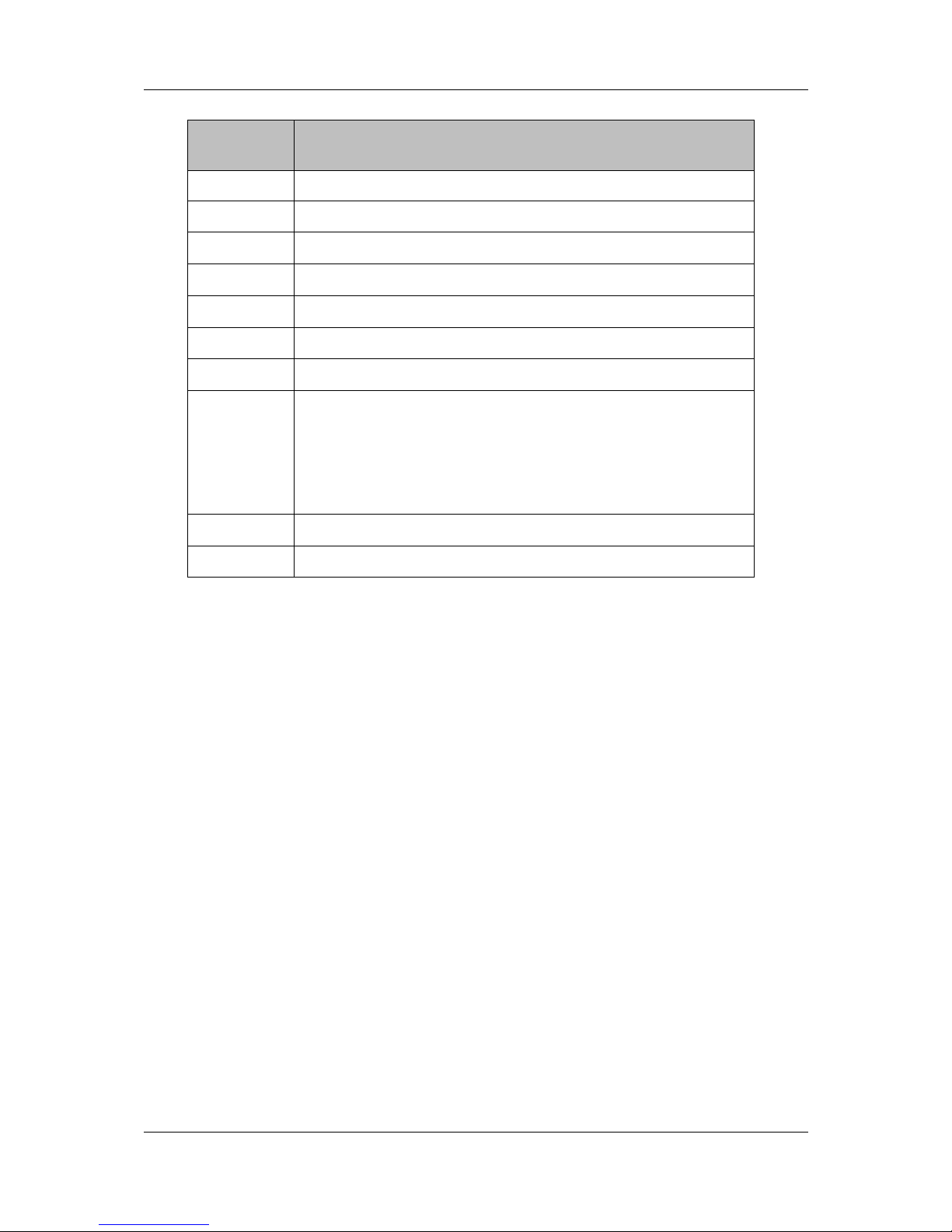
Chapter 4 Configuration
MAN_905G_1.16 Page 64
Supported Modbus Function Codes:
Function
Code
Meaning
01 Read the state of multiple digital output points
02 Read the state of multiple digital input points
03 Read the value of multiple output registers
04 Read the value of multiple input registers
05 Set a single digital output ON or OFF
06 Set the value of a single output register
07 Read Exception Status - compatibility - returns zero
08
Loopback test
Supported codes 0 return query data
10 clear diagnostic counters
11 bus message count
12 CRC error count
14 slave message count
15 Set multiple digital output points ON or OFF
16 Set multiple output registers
Analog I/O are 16 bit register values. A value of decimal 8192 (hex 2000) represents 0mA. A
value of 49152 (hex C000) represents 20mA. Each 1 mA has a value of 2048 (hex 0800) - a
change of 4096 (hex 1000) is equivalent to a change of 2mA. A 4-20mA signal will vary
between 16384 (hex 4000) and 49152 (hex C000). A 0-20mA signal will vary between 8192
(hex 2000) and 49152 (hex C000).
Pulse counts are stored as a 16-bit register. When the register rolls over, from ‘FFFF’ (hex),
the next value will be ‘0001’. The register will only have a value of ‘0000’ when the remote
module starts up, and the previous count is lost. This value will indicate that the counter has
reset.
Modbus Errors
Four Modbus error messages are reported to the Modbus Master. An error response is
indicated by the address of the return message being 128 plus the original slave address.
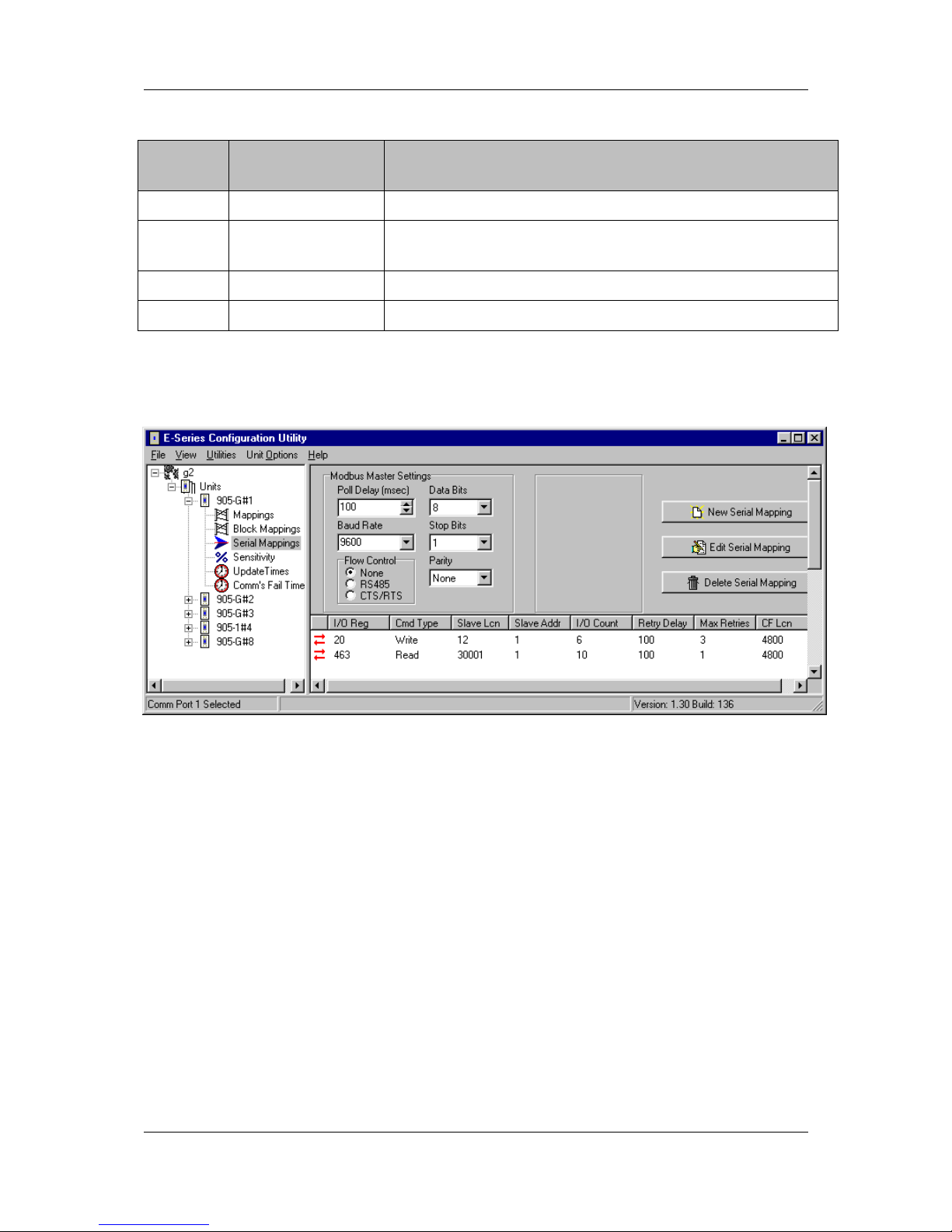
905U-G Wireless Gateway User Manual
Page 65 ©September 2004
Supported Exception Codes:
Exceptio
n Code
Name Description
01 Illegal function The module does not support the function code in the query
02 Illegal data address The data address received in the query is outside the
initialized memory area
03 Illegal data value The data in the request is illegal
06 Busy Unable to process message
4.6.2 MODBUS Master
If you use the 905G as a Modbus Master, then the host device/s will be Modbus Slave
device/s. If the RS485 port is used, then multiple Modbus Slave devices can be connected to
the 905G. The 905G Modbus Master will generate Modbus read and write commands to the
Modbus Slave devices.
First read the above section on Modbus Slave operation, for an understanding of how the
905G handles Modbus registers, and the types of Modbus commands the 905G Master can
generate.
The Modbus Master commands are configured in the “Serial Mapping” screen. The serial
port is configured in the same way as described in the above section on Modbus Slave.
To enter a Modbus command, select “New Serial Mapping”. The following example is a
digital write command which writes 905G I/O registers 20 – 25 (6 registers) to Modbus
outputs 00012 – 00017, at Modbus Slave address 1.
The entry under “I/O Register” is the first I/O register in the 905G to be transferred - the
“I/O count” is the number of registers to be transferred. If the selected Modbus slave does
not respond to the command, then the 905G will write a ‘FFFF’ value to one of its own
registers, configured under “CF Register” - in this case it is register 4800.
The “Command Type” selected is a write command (you can select read or write) - which
means that the values are sent from the 905G to the Modbus Slave. The type of write

Chapter 4 Configuration
MAN_905G_1.16 Page 66
command is a “Digital” write, meaning that the register values will be written as
digital/binary values”.
If the Modbus Slave device does not respond to the Modbus command, the 905G will try
another 3 times (“Max Retries” = 3). The Modbus command will be sent to the Modbus
Slave every 100msec. The address of the Modbus Slave is 1 (permissible addresses are 1 –
255). Because a digital write command has been selected, the destination register type will
be digital outputs, with Modbus tag “0xxxxx”. The first destination Modbus location is 12
(or 00012) - as there are 6 registers transferred, the destination locations will be 00012 –
00017.
The second example is a register read command to the same Modbus Slave (address 1). The
command requests the Modbus Slave to return the values of 10 registers which will be stored
in I/O registers 463 - 473 in the 905G. As the command is a “register read” command, the
target Modbus locations will be of the type 3xxxx. The starting location is 30001. So the
values of locations 30001 – 30010 in Modbus Slave 1 will be transferred to I/O registers 463
– 473 in the 905G.
The CF Register (“comms fail” register) acts as a digital alarm – the value of the register will
normally be 0, and will be set to FFFF (hex) if the slave device does not positively respond to
the serial command within Max Retries attempts. In the examples, the same CF Register
(4327 – i.e. DOT8) has been used for both serial mappings, such that the local digital output
will be activated if the slave fails to respond to either serial command. Alternately, any other
internal register could have been chosen and mapped via radio if desired.
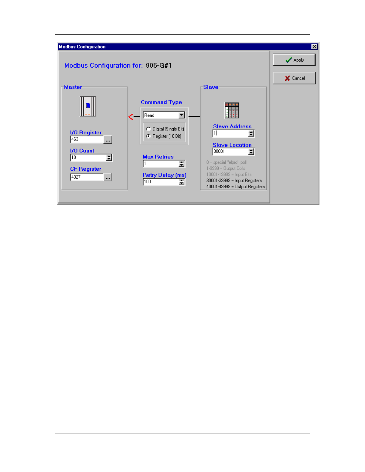
905U-G Wireless Gateway User Manual
Page 67 ©September 2004
To complete the Fieldbus Configuration, enter any other Modbus commands that may be
required to transfer I/O points between the 905G and the Modbus Slave devices.
Digital I/O
The value of a digital I/O point is stored in the 905G database as a hexadecimal '0000' (“off”) or
hex 'FFFF' (“on”). However the 905G will generate either a ‘0’ (“off”) or ‘1’ (“on”) to a digital
output point (Coil) when sending commands to a Modbus slave - these are commands 05 and 15.
Similarly, the 905G will accept ‘0’ or ‘1’ from the Modbus slave in response to a digital read
command and store ‘0000’ or ‘FFFF’ in the database location - these commands are 01 and 02.
Analog I/O
Analog I/O from the remote 905U modules are 16 bit register value. A value of 8192 (hex 2000)
represents 0mA. A value of 49152 (hex C000) represents 20mA. Each mA has value of 2048
(hex 0800) - a change of 4096 (hex 1000) is equivalent to a change of 2mA. A 4-20mA signal
will vary between 16384 (hex 4000) and 49152 (hex C000). A 0-20mA signal will vary between
8192 (hex 2000) and 49152 (hex C000).
Pulse I/O
Pulse counts from the remote 905U modules are shown as a 16-bit register. When the
register rolls over, from ‘FFFF’ (hex), the next value will be ‘0001’. The register will only
have a value of ‘0000’ when the remote module starts up, and the previous count is lost. This
value will indicate that the counter has reset.
Modbus Retry Delay
The 905G Modbus Master configuration includes a feature to limit the frequency at which slave
devices are polled for data. The 905G will poll each Modbus slave in order. If there is no delay
time entered, the 905G will poll as quickly as it is able to. If there is a delay time entered, then
this delay time will occur between each poll message.

Chapter 4 Configuration
MAN_905G_1.16 Page 68
When updated values are received from the 905U radio network, the current polling sequence is
interrupted, and the new values are written immediately to the appropriate slaves.
Re-tries on the Serial Port
When communicating with Modbus slaves, the 905G may be configured to re-try (or re-send)
a message zero or more times if no response is received from a slave. If all retries are used
up, that slave is flagged as being in communication failure. Further attempts to communicate
with the slave will have zero re-tries. When a successful response is received from the
Modbus slave, the communication failure flag is reset and the configured number of re-tries
will be used. This means that an off-line slave device will not unduly slow down the
communications network.
Comms Fail
A “Comms Fail” image location in the 905G database. This image location should be in the
range 4500 to 4999. If a response is not received from the Modbus slave after all re-tries
have been sent, the 905G will set this Comms Fail image location to hex(FFFF). When the
905G sends the next poll for this I/O Command, it will not send any re-tries if a response is
not received to the first message. When a response is eventually received, the 905G will
reset the value in Comms Fail image location to 0, and the normal re-try sequence will
operate.
Different I/O Commands can use different Comms Fail image locations, however we
recommend that you use the same image location for all I/O Commands to the same Modbus
slave address.
4.7 Serial Configuration - DF1
The 905G DF1 Driver allows the 905G to communicate with Allen-Bradley devices
supporting the DF1 protocol. Supported commands allow communication with 500 CPU
devices (SLC and Micrologix) and with PLC2 series devices. DF1 offers both full-duplex
(point to point) and half-duplex (multidrop) operation. The 905G only supports the fullduplex operation - this is the default DF1 mode on most equipment. DF1 full-duplex is a
“peer-to-peer” protocol. Either DF1 device can initiate commands to the other device, and
both devices will respond to commands from the other device. The 905G can act as both a
command initiator and a command responder.
An Application Note and configuration files are available describing how to configure an
Allen-Bradley PLC to communicate with a DF1 905G. This is available from the Elpro
website www.elprotech.com
The 905G will initiate the following command types to a command responder, according to
the configuration. The 905G will automatically generate the correct command type
depending on the configuration you enter. The 905G will also respond to these command
types if they are sent from a command initiator.

905U-G Wireless Gateway User Manual
Page 69 ©September 2004
Command Description Code Function
Code
Comment
Protected Write 0x00
NONE
PLC2 series and SLC / Micrologix
Unprotected Read 0x01
NONE
PLC2 series and SLC / Micrologix
Diagnostic Status 0x06
0x00
Diagnostic Commands
Echo message 0x06 0x00
Unprotected Write 0x08
NONE
PLC2 series and SLC500 / Micrologix
Typed logical Read 0x0F 0xA2 Type SLC500 and Micrologix
Read Bits
0x0F
0xA2 0x85 Reads MSB of each 905G I/O register and
writes the bits to the destination register,
starting at the LSB of the register. Min.
transfer is 16 bits.
Read Integers
0x0F
0xA2 0x89 Return signed 16 bit value
Read Long Ints
0x0F
0xA2 0x91 Unsigned 16 bit register per long-word
Typed logical Write 0x0F 0xAA Type SLC500 and Micrologix
Write Bits
0x0F
0xAA 0x85 Writes bits from the source register, starting
at the LSB, to the MSB of a block of 905G
I/O registers. Min. transfer is 16 bits.
Write Integers
0x0F
0xAA 0x89 Writes a signed 16 bit value
Write LongIntegers
0x0F
0xAA 0x91 Low 16 bits of long-word placed in register.
Upper 16 bits ignored.
The SLC and Micrologic PLC’s read/write two types of registers. An “Integer” has a signed
16 bit value (-32768 to 32767). A “Long Integer” has a 32 bit value. The 905G registers
contain an unsigned 16 bit value (0 to 65535). We recommend that you use Long Integer
read/write commands - the upper 16 bits of the 32 bit value will be ignored. Refer to more
information in the Analog I/O and Pulse I/O sections below. The PLC2 uses unsigned 16 bit
registers in the same format as the 905G.
The 905G DF1 driver will update remote outputs whenever a data value changes by more
than the I/O register sensitivity. If the response from a data request contains a changed data
value, the new value will be transmitted to the remote 905U on the radio network. Similarly,
if the 905G receives a command to change a data value, the new value will be transmitted to
the remote 905U module.
The DF1 commands are configured in the “Serial Mapping” screen. The serial port should be
configured in the same way as the host device. If the 905G acts only as a command
responder, no further configuration is required.

Chapter 4 Configuration
MAN_905G_1.16 Page 70
If the 905G acts as a command initiator, you can enter a “Request Delay” between
commands sent to the host. To enter a DF1 command, select “New Serial Mapping”. The
following example is a file write command which writes 905G I/O registers 80 – 104 (25
registers) to DF1 files I3.1 to I27.1 at DF1 address 2.
The entry under “I/O Register” (see below) is the first I/O register in the 905G to be
transferred - the “I/O count” is the number of registers to be transferred.
The “Command Type” selected is a file write command (you can select read or write) which means that the values are sent from the 905G to the host device. The type of write
command is a “Integer” write, meaning that the register values will be written as register
values.
The DF1 address of the host device (or “Slave”) is 2.

905U-G Wireless Gateway User Manual
Page 71 ©September 2004
Discrete I/O
The value of a digital I/O point is stored in the 905G database as a hexadecimal '0000' (“off”) or
hex 'FFFF' (“on”). However the 905G will generate either a ‘0’ (“off”) or ‘1’ (“on”) to a binary
file when initiating a “Typed Logical Write” command or responding to a “Typed Logical Read”
command. Similarly, the 905G will accept ‘0’ or ‘1’ from responding device to a “Typed
Logical Read” command or from an initiating device generating a “Typed Logical Write”
command and store ‘0000’ or ‘FFFF’ in the database location. The file type for a binary file (bit
file) is 0x85.
In the PLC (that is, the DF1 host device), discrete values (“bits”) are stored in 16 bit registers each register stores 16 bit values (or 16 discrete values). You can only transfer these values in
groups of 16. That is, a read or write command will transfer a minimum of 16 bits to/from the
905G. If more than 16 are transferred, then they will be transferred in multiples of 16. You
cannot transfer an individual bit - you must transfer the 16 bits in that PLC register, which will
be transferred to/from 16 consecutive I/O registers in the 905G.
Note: The PLC reads or writes digital bits starting at the LSB of each register. In the 905G,
only one bit is written to each I/O register, and this is the MSB.
Analog I/O
Analog I/O from the remote 905U modules are 16 bit register value. A value of 8192 (hex 2000)
represents 0mA. A value of 49152 (hex C000) represents 20mA. Each mA has value of 2048
(hex 0800) - a change of 4096 (hex 1000) is equivalent to a change of 2mA. A 4-20mA signal
will vary between 16384 (hex 4000) and 49152 (hex C000). A 0-20mA signal will vary between
8192 (hex 2000) and 49152 (hex C000).
Note: If analog values are read to and written from an integer file in an SLC or Micrologix CPU,
integer files contain 16 bit signed values. These represent values in the range -32768 to 32767.
The data values from the 905U modules are treated as 16 bit unsigned values. To convert the
data from an analog input, move the data from the integer file to a long file (MOV command)

Chapter 4 Configuration
MAN_905G_1.16 Page 72
then mask out the high 16 bits (MVM with mask value FFFF). This will result in a long integer
value in the range 0 to 65535.
Alternatively, use a long integer file type to transfer the analog value as a long integer in the
range 0-65535.
Pulse I/O
Pulse counts from the remote 905U modules are shown as a 16-bit register. When the
register rolls over, from ‘FFFF’ (hex), the next value will be ‘0001’. The register will only
have a value of ‘0000’ when the remote module starts up, and the previous count is lost. This
value will indicate that the counter has reset.
Note: The values from the 905G module are 16 bit unsigned values. When they are copied to
the Integer file in the PLC, they will be treated as 16 bit signed values. These values may be
converted to the original (unsigned) values using the MOV and MVM instructions described
in the previous section (Analog I/O). Again, using a Long Integer type will avoid this
problem.
500 CPU (SLC and MicroLogix) file types and addressing
The 905G provides a linear address space of 10,000 data words. This is compatible with
PLC2 addresses, but does not match the addressing used by the 500CPU modules (SLC and
Micrologic). These address data by file number and file offset. To address an I/O register, L,
in the 905G, use DF1 file number L / 100, with the remainder value (L % 100) as the DF1
file offset. For example, to read I/O register 2643 in the 905G, read from file number 26,
offset 43.

905U-G Wireless Gateway User Manual
Page 73 ©September 2004
4.8 Fieldbus Configuration
All 905G modules (except MD1) have separate internal hardware comprising the Fieldbus
Interface, consisting of a separate microprocessor and appropriate hardware for the network
connection. This Fieldbus Interface handles all fieldbus communications, and transfers I/O in
the Fieldbus Interface Registers to/from the fieldbus. Conversely, the 905G Radio Interface
handles all radio communications, and transfers I/O in the Radio Interface Registers to/from
the radio network. For I/O transfer between the radio network and the fieldbus network, I/O
Registers in the Radio Interface must be linked with registers in the Fieldbus Interface using
configuration software.
Depending on the fieldbus protocol, the size of the Fieldbus Interface may be limited (for
example, the Profibus Slave interface supports only 416 bytes I/O). The Radio Interface
supports 10,000 registers, of which 4300 are general-purpose I/O registers. Each Radio
Interface register is 16-bit, even for discrete (or “digital”) input or output values. The
Fieldbus Interface comprises a block of 8-bit bytes (referred to as “locations”). Digital I/O
can be packed - each fieldbus location can hold 8 digital inputs or outputs. Analog or pulse
values can be stored as a low resolution 8-bit value (a single fieldbus location) or as a high
resolution 16-bit value (two consecutive fieldbus locations).
To optimize I/O usage, the 905G provides a flexible method of data transfer between the
Radio Interface and the Fieldbus Interface. The user configures links between the Radio
Interface and Fieldbus Interface via Fieldbus Mappings in the ESeries Configuration
Software. The diagram shows in more detail the relationship between the Radio Interface and
Fieldbus Interface.
WRITE
RADIO
INTERFACE
I/O
DATABASE
I/O REGISTERS FIELDBUS
LOCATIONS
READ
FIELDBUS
INTERFACE
RADIO
DRIVER
DATA BUS
ANTENNA

Chapter 4 Configuration
MAN_905G_1.16 Page 74
4.8.1 Fieldbus Mappings
The Fieldbus Interface is divided into two distinct areas. The IN Area contains input data that
is made available to the host device. The OUT Area contains output data from the host
device. This is in contrast to the Radio Interface, in which each 16-bit register can be used as
input or output. Also note the size of the Fieldbus Interface is variable, depending on the type
of fieldbus.
ESeries Configuration Software provides user configurable Fieldbus Mappings to link the
required Fieldbus I/O to the Radio Interface. Write mappings write I/O values from the
Radio Interface to the Fieldbus IN Area. Read mappings read I/O values from the Fieldbus
OUT Area to the Radio Interface.
If you want to send a value from the 905G to the host device, use a Fieldbus Write Mapping.
The input data from the Radio Interface (i.e. input data that has either come in from the radio
or from local I/O) will be transferred to the IN Area via the fieldbus write mapping. The host
device can then read this input data from the IN Area.
If you want to send a value from the host device to the 905G, use a Fieldbus Read Mapping.
The host device can write output data to the OUT Area. The output data from the OUT Area
will then be transferred to the Radio Interface via the fieldbus read mapping. The radio driver
can then either send this output over the radio or to a local I/O.
Several different configurable transfer modes are also available for fieldbus mappings to
ensure the I/O is formatted according to the requirements of the particular fieldbus protocol
or host device. The six possible types of Fieldbus Mapping are outlined in the table below.
905G Module
IN Area
OUT Area
Radio Interface
Write
from
I/O
Re
g
Read to
I/O Reg
Fieldbus Interface
Write from
Host
Read from
Host
Fieldbus
Profibus 244 Bytes
Modbus/TCP 2048 Bytes
Ethernet/IP allows 6 input
connections; each
connection Max 512 bytes
Modbus Plus 2048 bytes
DeviceNet 512 bytes
Profibus 244 Bytes
Modbus/TCP 2048 Bytes
Ethernet/IP allows 6
output connections; each
connection Max 512 bytes
Modbus Plus 2048 bytes
DeviceNet 512 bytes
10,000 x 16-bit
I/O Registers

905U-G Wireless Gateway User Manual
Page 75 ©September 2004
Fieldbus Mapping Types
Transfer Mode Read Mapping Write Mapping
Single Bit
The 905G reads a block of
consecutive bits from Fieldbus OUT
Area and stores each bit in
consecutive I/O Registers, as hex
FFFF or 0000.
The 905G takes the MSB (most
significant bit) of a block of
consecutive I/O Registers, converting
the 16 bit I/O register values into 0 or
1, and writes to consecutive bits of
Fieldbus IN Area.
Byte (8-bit)
The 905G reads consecutive bytes
(8-bit values) from Fieldbus OUT
Area and stores each byte in the most
significant 8-bits of a consecutive I/O
register.
The 905G takes the most significant
8-bits of consecutive I/O registers
and writes them to consecutive bytes
(8-bit values) of the Fieldbus IN area.
Word (16-bit)
The 905G reads consecutive words
(2x8-bit values) form Fieldbus OUT
Area and stores each word in a
consecutive I/O Register.
The 905G takes consecutive I/O
registers and writes them to
consecutive words (2x8-bit values) of
Fieldbus IN Area.
4.8.2 Transfer Mode
Radio Interface registers are all 16-bit general-purpose input or output registers. That is,
analog inputs or outputs are stored as a 16-bit value. Digital inputs or outputs occupy a whole
16-bit register and are stored as either 0000(hex) or FFFF(hex) for compatibility with the
ELPRO Radio Protocol. However, the Fieldbus Interface may contain (depending on the
protocol) significantly less registers than the Radio Interface (see diagram above). Also,
certain protocols may require a different I/O structure than that used by the Radio Interface
registers. Consequently, depending on the fieldbus mapping transfer mode (see above table),
Radio Interface registers may or may not be compressed.
“Word” transfer mode offers no compression, but rather a direct transfer of 16-bit registers
between Radio Interface and Fieldbus Interface. This mode would suit the transfer of
registers containing pulse counts or analog values with no loss of resolution.
“Byte” transfer mode operates on only the most significant BYTE (the first 8 bits) of Radio
Interface registers, but allows these bytes to be consecutively packed in the Fieldbus
Interface. This mode would suit the transfer of analog values in low-resolution, in cases
where I/O space is at a premium. Byte Address Mode is recommended when using byte
transfer mode (see Address Mode section below).
Bit transfer mode operates on only the most significant BIT of Radio Interface registers, but
allows these bits to be consecutively packed in the Fieldbus Interface. This mode would suit
the transfer of digital I/O in cases where it is not desirable (or possible) to use a whole 16-bit
register just to store a 0 or 1 value.
4.8.3 Address Mode
Configuration software allows the Fieldbus Interface IN and OUT areas to be addressed as an
array of 8-bit bytes (Byte Address Mode) or an array of 16-bit words (Word Address Mode).
The address mode may be required to change depending on the transfer mode, the protocol,
or the particular host device. The Address Mode option is included so that the configuration
software can be setup to use the same I/O addressing method used by the host device. The
actual structure of I/O in this database can only be physically altered via the transfer mode.

Chapter 4 Configuration
MAN_905G_1.16 Page 76
The Fieldbus Interface IN and OUT areas are simply a block of I/O memory, exchanged
according to the configured protocol. For example, with a Profibus slave that supports 244
bytes of inputs, the fieldbus interface IN area could be addressed either as byte locations 1 to
244 or as word locations 1 to 122. Note that in either case, the underlying database structure
is unchanged, the difference is limited to the Fieldbus IN/OUT Area address that is displayed
by configuration software.
Certain protocols have an inherent or preferred byte or word structure – for example,
Modbus is a protocol that usually operates on 16-bit (word) registers. Consequently,
configuration software will default to the most common address mode for that protocol.
Configuration software may also apply an offset and/or scaling to the IN/OUT Area
addressing to suit the particular protocol. For example Modbus/TCP areas start from location
1, but other fieldbuses may start at location 0.
Note:
• The Fieldbus Interface IN and OUT Area both number from 0 - that is, there is an input
0 as well as an output 0 (an offset may apply for some protocols).
• All IN/OUT Area locations accessed by the fieldbus must be part of a fieldbus mapping
in the 905G - that is, if a host device is writing to bytes 0 – 100 in the OUT Area, there
must be at least one fieldbus read mapping that uses these locations - if not, the Fieldbus
Interface will generate an error response message.
• Fieldbus mappings to/from the IN/OUT areas should always start at location 0 if possible
(or the lowest available unused location). Configuration Software will always
automatically choose the next lowest available location – it is strongly recommended that
this topology be used so as not to place unnecessary processing overhead on the module.
4.8.4 Fieldbus Mapping Configuration
The example below shows the Fieldbus Mapping configuration screen when adding new or
editing existing Fieldbus Mappings. Starting from the left of the screen, the I/O Register
selection specifies the starting I/O Register from the Radio Interface (press the “…” button to
make a selection graphically). The I/O Count parameter specifies how many consecutive I/O
Registers are to be transferred or linked. Command Type and Transfer Mode specify the type
of Fieldbus Mapping (see Fieldbus Mappings table above). Finally, I/O Location specifies the
IN or OUT Area location in the Fieldbus Interface (see earlier diagram).

905U-G Wireless Gateway User Manual
Page 77 ©September 2004
Three Fieldbus Mappings are illustrated in the example above. Note that “Word Address
Mode” is selected, meaning that the Fieldbus Interface IN and OUT Areas will be treated as
word-addressed arrays by configuration software. The parameters for each fieldbus mapping
were setup using the mapping configuration screen as described above.

Chapter 4 Configuration
MAN_905G_1.16 Page 78
The first Fieldbus Mapping is a “Write WORD” mapping, writing I/O Registers 10 – 15 from
the Radio Interface to word-locations 1 – 5 in the Fieldbus IN Area. Because the transfer
mode is “word” complete 16-bit registers are transferred.
The second mapping is a “Read BIT” mapping, reading 12 bits from Fieldbus OUT Area
word-location 1(word address mode is selected) to I/O Registers 30 – 41. Remember that for
such a BIT transfer, that each individual bit in the Fieldbus Interface is transferred to an
entire 16-bit I/O Register. Note also that there is a word-location 1 for both the Fieldbus OUT
and IN areas.
The third mapping is another “Read BIT” mapping, reading 8 bits from Fieldbus OUT Area
word-location 1 to I/O Registers 4320 – 4327 (i.e. local DOT 1 – 8). Note here that we are
again reading from Fieldbus OUT Area word-location 1 (as with the previous mapping).
However, since each word-location contains 16-bits and the last mapping used only 12 of
those, we have been able to follow on from the previous mapping (see below).
The Fieldbus Register Selection screen above was shown when selecting the Fieldbus OUT
Area location for the third mapping in the above example. This screen shows the currently
used portion of the Fieldbus OUT Area, and allows the user to graphically select the location
for the current mapping. NOTE – by default configuration software will always choose the
next available Fieldbus Interface register for fieldbus mappings. Allowing configuration
software to automatically make the selection is strongly recommended wherever possible.
Clicking on the required location in the top panel will alter the currently selected wordlocation. Further, clicking individual bits in the “Bit Usage” panel at the bottom of the screen,
allows the current BIT mapping to be specified at the bit-level of the currently selected word.
The lighter blue areas indicate the extent of already existing fieldbus mappings. It can be seen
that bits 0 – 11 of word location 1 have already been used (by the second mapping in the

905U-G Wireless Gateway User Manual
Page 79 ©September 2004
example). The dark blue area in the register selection screen above shows the extent and
location of the current fieldbus mapping graphically. The status panel at the bottom of the
window always displays the extent of the current selection, which can be seen to be word 1,
bit 12 to word 2, bit 3.
A status location (4500) may be used to give the host device status information about the
Fieldbus Interface. This register will be value 0x0000 if the Fieldbus Interface is “on-line”
and communicating with the fieldbus, or value 0xFFFF if it is “off-line”. If you wish to use a
status register, select the “Enable Status Location” box. This register could be mapped to a
remote module or local output as an alarm.
4.9 Fieldbus Configuration - Profibus Slave
The Profibus 905U-G-PR1 acts as a Profibus DP Slave - the host device is a Profibus
Master. If you use the 905U-G with a PLC, the PLC configuration tool will require a GSD
file so it can recognize the Profibus interface in the 905U-G. This file loads into the PLC
configuration software (for example, Siemens STEP 7). The file is available on the same CD
as the configuration software or from the Elpro web page www.elprotech.com.
Configuration of the Profibus Fieldbus Interface comprises allocating a Profibus Slave
address to the 905G, and configuring links between the Radio Interface and the Fieldbus
Interface (i.e. Fieldbus Mappings).
The Profibus address can be set in the “Fieldbus Config” screen or via the rotary switch on
the end-plate of the module- valid slave addresses are 1 – 126. If the “Enable Rotary
Switch” box is not selected, then the address entered in the program will be used and the
rotary switch value ignored. If the “Enable Rotary Switch” box is selected, then the address
entered in the configuration program will be ignored and the rotary switch read on start-up of
the 905G.
The Profibus interface has 416 bytes, of which 244 can be used as input bytes, or 244 can be
used as output bytes.
Note: For bit transfers, the bit offset is counted from the least significant bit (LSB) of the byte
(with bit 0 being the LSB) - if you transfer 3 bits with a bit offset of 5, then you will
transfer bits 5-7 of the byte. This is different than the Ethernet unit which counts the offset
from the most significant bit - refer next section.
An application note for configuring a Siemens S7 PLC to communicate with a Profibus 905G
can be downloaded from the Elpro web-site www.elprotech.com
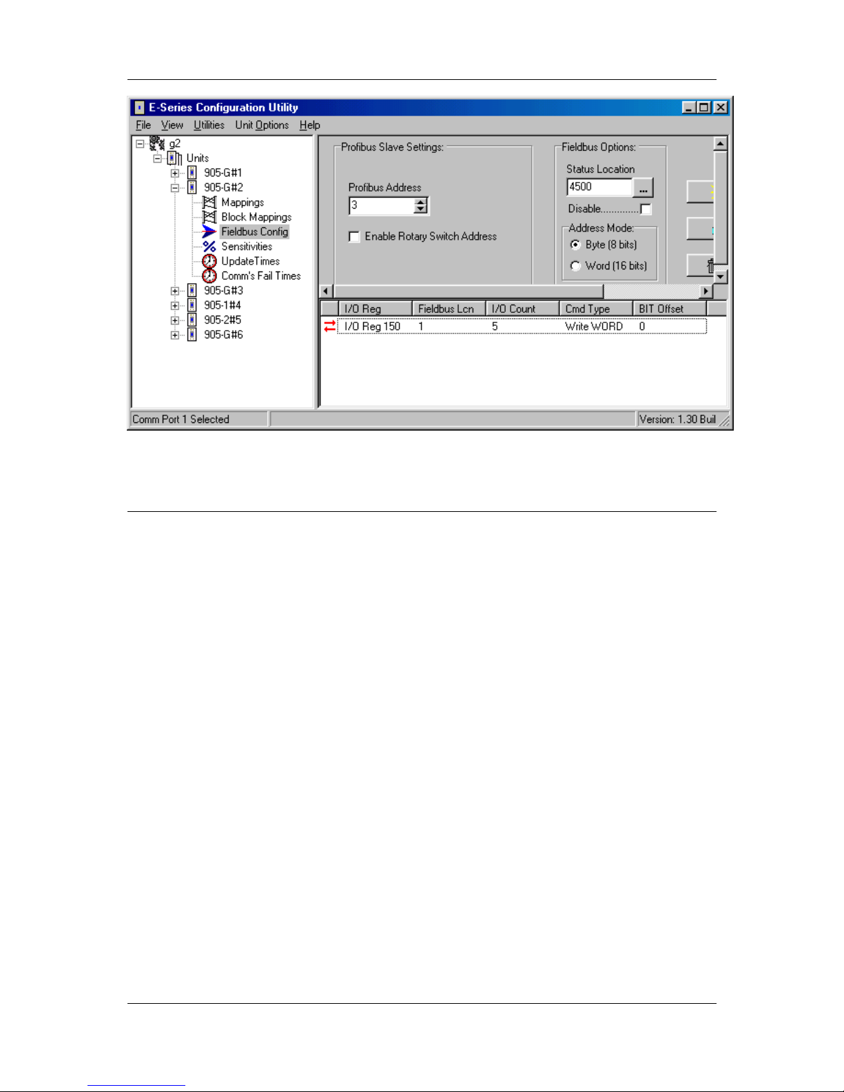
Chapter 4 Configuration
MAN_905G_1.16 Page 80
4.10 Fieldbus Configuration - Profibus Master
The 905U-G-PR2 implements a complete Profibus-DPV0/DPV1 master. The hardware is
optimized for high throughput and can be used in mono or multi master networks up to 12
Mbit/s. Up to 125 slaves with a total max of 2048 byte input and 2048 byte output data can
be connected.
4.10.1 GSD File
Each device in a Profibus network is associated with a GSD file, containing all necessary
information about the device. In general, the profibus slave device manufacturer supplies the
relevant GSD files. ESeries Configuration Software uses these files during network
configuration.
4.10.2 Protocol and Supported Functions
The 905U-G-PR2 implements a complete Profibus-DPV0/DPV1 master and includes the
following features:
• Up to 125 slaves can be connected
• Up to 2048 bytes input &output data
• Up to 12 Mbit/s on Profibus
• RS-485 optically isolated Profibus interface with on-board DC/DC converter
• Configuration via ESeries Configuration Software
• Acyclic Communication (DPV1)
• Alarm Handling (DPV1)
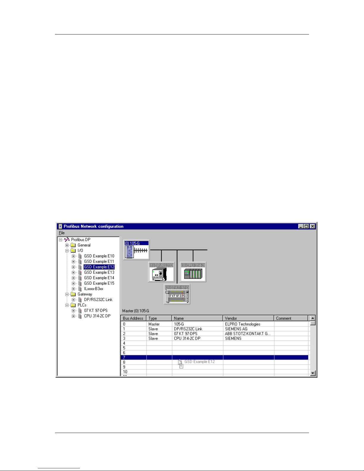
905U-G Wireless Gateway User Manual
Page 81 ©September 2004
4.10.3 Configuration
Profibus network configuration is performed via the ESeries Configuration Utility. The
905G Profibus Master provides up to 2048 bytes of inputs and 2048 bytes of outputs in the
fieldbus interface for I/O on the profibus network. I/O in the fieldbus interface must be linked
with I/O in the radio interface via appropriate fieldbus mappings (see 4.8 Fieldbus
Configuration above) for I/O transfer with the radio network.
Configuration of the profibus network is through the Profibus Network Config tab in ESeries
Configuration Software. Through this section, the entire (local) profibus network including
I/O data transfer with profibus slaves is configured. Before a profibus slave is configured on
the network, its corresponding GSD file must be installed. To install a GSD file choose
File|Install GSD File. Once the GSD file(s) have been installed, the devices corresponding to
those GSD files will appear as devices on the Profibus DP treeview on the left side of the
network configuration screen.
The profibus network configuration screen is divided into three main areas (see below). The
left hand Profibus DP Treeview displays all the available slaves, i.e. those whose
corresponding GSD files have been installed. The right hand top section Busview displays
graphically the devices that are currently configured on the profibus network – individual
devices can be selected here and their I/O configuration and other properties viewed/altered.
The right hand bottom section Listview shows the I/O configuration of a particular slave
when a slave device is selected in the busview, or the netowrk configuration (i.e. what slaves
are configured and their corresponding addresses) when the profibus master node is selected
in the busview.
Adding a Slave to the Network
To add a profibus slave to the network, locate the required slave and simply drag the slave
icon onto the visible bus cable on the busview, or right click the required slave and choose
add to network. To add a slave with a specific profibus node address to the network, locate
the required slave and drag the icon to the network listview (ensure that the master node is

Chapter 4 Configuration
MAN_905G_1.16 Page 82
selected in the busview so that the network list is displayed in the listview rather than the
slave I/O configuration list). The above example shows a slave device being added to the
network at node address 7.
Slave Address
To change the node address of a slave already configured on the network, locate the slave in
the network listview and drag it to the position in the list corresponding to the desired
address. Alternately, the slave address can be modified from the module properties page (see
below).
Module Properties (Slave)
To display the properties of a given slave, right click the required slave in the busview and
choose properties (or double click the icon in the busview). Under the general tab, various
details (including GSD file details) relating to the selected slave device are displayed. Several
configurable options are also available (see below).
Profibus Address
The actual profibus address of the selected slave is shown in the address selection box. Only
available addresses are listed and can be selected as new address.
Watchdog
According to the profibus specification, a slave device may be configured with a watchdog
function such that the master must poll the slave within a defined interval. If this feature is
enabled and the master fails, the slaves watchdog timer will timeout and the slave will reset
itself.

905U-G Wireless Gateway User Manual
Page 83 ©September 2004
Group Assignment
If the slave supports sync/freeze functionality, it can be assigned to the masters sync/freeze
groups by clicking on the checkboxes. The sync/freeze assignment of the groups is also
displayed (these can be changed via the master properties dialog).
Parameter Assignment
A slaves user-specific parameters can be changed via the parameter assignment page. Userspecific parameters for a slave device are defined in the corresponding GSD file for the
device, the definition of which are device-specific and should be found in the documentation
for the device.
Parameters can be altered via combo boxes or via direct input of hexadecimal values. The
hexadecimal values for the user_prm_data are displayed at the bottom of the screen and can

Chapter 4 Configuration
MAN_905G_1.16 Page 84
be edited directly (consult the device specific documentation for the meaning of these
values).
Adding I/O to a Slave
The possible I/O combinations for a given slave may be fixed or configurable (i.e. modular)
depending on the GSD file for the device. When the I/O configuration is fixed, the fixed I/O
are always defined whenever the device is added to the network. However, for modular
devices, the I/O configuration must be assigned manually.
The GSD file for a modular slave will define a maximum number of I/O slots – each of which
may be configured with an I/O module. The available I/O module’s for a particular slave can
be viewed by expanding the slave node in the Profibus DP Treeview. To add an I/O module
to a slave, first ensure the required slave is selected in the busview, then drag the required I/O
module into a spare slot of the slave listview.
When an I/O module is added to a slave, configuration software will automatically assign that
I/O to the next available space in the fieldbus interface. The input and output addresses that
are assigned here will correspond to the locations that must be transferred via fieldbus
mappings in order to make the I/O available to the radio network. The input and/or output
address assigned by software for a given I/O module can be altered by double clicking on that
I/O module entry in the slave listview (see above).
The start address in the fieldbus interface for the inputs or outputs can be altered in the
corresponding Start field as shown above. Since the 905G provides for up to 2048 bytes of
inputs and 2048 bytes of outputs, the possible range for inputs or outputs is 0 – 2047.

905U-G Wireless Gateway User Manual
Page 85 ©September 2004
I/O modules may also have associated user parameter data defined by the corresponding
GSD file. The meaning of these parameters (if applicable) is specific to the slave
implementation, and may be altered via the Parameter Assignment tab of the Module
Properties form.
Configuration software also provides an additional I/O module to all slaves that is not defined
in the GSD files, which is the Universal Module. The universal module allows the
input/output length, unit, and consistency to be assigned custom values as required – however
not all slave implementations will support this feature (consult the specific slave
documentation for details).
The Length parameter defines the length of the input or output module in either bytes or
words (according to the corresponding Unit parameter). The data consistency over the
profibus network may be applied to the selected unit (i.e. byte or word) or to the total length
of the input or output selection.
Depending on the particular slave, Manufacturer Specific Data may also apply to an I/O
module. This data is a string of hexadecimal bytes, the meanings of which (if applicable) are
device specific and should be detailed in the documentation for the particular device.
Master Properties
The profibus master 905G has some configurable properties that affect the entire profibus
network. These properties can be accessed by double clicking the master icon in the network
busview, or right-clicking the icon and choosing properties.
Profibus Tab
The Address parameter specifies the actual profibus address of the profibus master (default =
0). Only available addresses are listed and can be selected as new address. The serial baud
rate for the entire profibus network is selected – this is the baud rate that will be used by the
master and therefore must also be supported by all slave devices on the network. Most slaves
will support auto baud rate detect, but it should be ensured that any slave on the network
supports the configured baud rate.
The Profile parameter controls the assignment of Bus Parameters for the profibus network.
In the single master
(default) profile, the bus
parameters are calculated
automatically by
configuration software
and are optimised for
speed – no other masters
may be connected to the
network. The User
Defined profile allows the
bus parameters to be
manually configured for
special network
configurations and should
only be used if the user is
familiar with the
individual profibus

Chapter 4 Configuration
MAN_905G_1.16 Page 86
parameters (see Bus Parameters Tab below).
The storage format determines if word values are stored in big endian (Motorola – most
significant byte has lowest address) or little endian (Intel – Least significant byte has lowest
address) format.
Group Properties Tab
A DP master can send the SYNC and/or FREEZE control commands simultaneously to a
group of slaves for synchronization purposes. Therefore the slaves must be assigned to
Sync/Freeze - groups. Up to 8 groups may be configured as SYNC and/or FREEZE groups.
Any slaves that are configured to belong to a particular group (via that slaves module
properties|group assignment configuration) may be synchronized using the Message
Interface instruction SET_SLAVE_MODE (see section on the Message Interface below).
Bus Parameters Tab
The bus parameters can be adjusted only when the selected profile is user defined (see
Profibus Tab above). These parameters should only be changed if the user is familiar with the
individual profibus parameters according to the profibus specification.
Adjustable bus parameters:
Tslot
The slot time determines the maximum length of time the sender has to wait to receive a
response from the partner.
Max. Tsdr + 15 <= Tslot <= 16.383 t_bit
Max Tsdr
The maximum station delay responder determines the maximum length of time required by
the responding node to respond
35 + 2*Tset + Tqui <= Max. Tsdr <= 1.023 t_bit
Min Tsdr
The minimum station delay responder determines the minimum length of time permitted for
the responding node to respond.
11 t_bit <= Min. Tsdr <=Max. Tsdr - 1
Tset
The setup time determines the length of time elapsing in the node between a data frame being
received and a response occuring
1 t_bit <= Tset <= 494 t_bit

905U-G Wireless Gateway User Manual
Page 87 ©September 2004
Tqui
The quiet time is the time a modulator needs after recognizing a send frame to switch from
send to receive.
0 t_bit <= Tqui <= MIN(31 t_bit, Min. Tsdr - 1)
Gap Factor
The Gap Factor determines how many token rounds occur before a new active node (master)
can be added to the token ring.
1 <= Gap Factor <= 100
Retry Limit
The Retry Limits determines the number of attemps (repeated message frames) allowed to
access a node.
1 <= Retry Limit <= 15
HSA
All active nodes (masters) scan the network continuously up to the HSA (highest station
address). HSA must be set at minimum to the highest profibus address (master or slave)
connected to the network.
0 <= HSA <= 126
Delta_Ttr
This value can be set for multi master networks with the selected profile Multi Master. Delta
Ttr is added to the calculated Ttr to increase the Ttr for using multiple masters in a network.

Chapter 4 Configuration
MAN_905G_1.16 Page 88
256 t_bit <= Ttr <= 16.776.960 t_bit
Non-adjustable bus parameters
Ttr
The target rotation time determines the maximum available time for a token pass. During this
time all active nodes (masters) obtain the token one time to send data. ESeries Config
Software calculates an optimized Ttr depending on the values of other bus parameters. If an
individual bus parameter is changed, pressing the Recalculate-button recalculates the Ttr
including Delta_Ttr.
Watchdog
The watchdog determines the watchdog time transferred to slaves if the watchdog is enabled.
Tid2
The idle time 2 determines the maximum length required before a transmitting node can send
the next message after sending a message frame that is not acknowledged.
Tid2 = Max. Tsdr
Tid1
The idle time 1 determines the minimum length required before a transmitting node can send
the next message after sending a message frame that is not acknowledged.
Tid1 = 35 + 2*Tset + Tqui
Trdy
The ready time determines the minimum time for a transmitting node to receive a response
message frame.
Trdy = Min. Tsdr

905U-G Wireless Gateway User Manual
Page 89 ©September 2004
Configuration Example:
The Following example describes a simple configuration of a 905G connected to a simple
Profibus Slave I/O device. Described is the configuration of the local 905G Profibus master
only, for more detailed configuration examples, an application note can be downloaded from
www.elprotech.com.
The example will transfer 8 x digital points from the radio network to the slave device. A
single 16-bit analog value will be transferred from the profibus slave to the radio network.
Several configuration steps via ESeries Configuration Software are required:
• Profibus Network Configuration
• Fieldbus Configuration (Fieldbus Mappings)
• Radio Configuration (I/O or Block Mappings)
1) Profibus Network Configuration
Once the GSD file for the profibus slave has been installed, the slave device can be added to
the profibus network (see Configuration section above). For this example, the slave is a
modular device, therefore we add the necessary I/O modules to the slave. The example
requires 8 x digital points to be transferred to the slave - hence we add the ‘1 Byte Out’
module - and 1 x analog point (16-bit) to be transferred from the slave – hence we add the ‘2
Byte In’ module (see below).
When these modules are added, configuration software automatically picks the next free
fieldbus interface registers (shown in the Input Address and Output Address columns), which
may later be altered by double-clicking on the relevant I/O module. In this example, the
automatically chosen locations are Fieldbus IN locations 0..1, and Fieldbus OUT location 0.

Chapter 4 Configuration
MAN_905G_1.16 Page 90
2) Fieldbus Configuration.
The next configuration step is to transfer the I/O in the Fieldbus Interace to the Radio
Interface so that the profibus I/O is available to the radio network. The 8 x digital output to
be sent to the profibus slave are transferred using a fieldbus write mapping. Since the 8 x
digital outputs are all contained in a ‘1 Byte Out’ module, we use ‘Single Bit Mode’ for the
fieldbus write mapping. The configured mapping (see below) transfers the 8 x I/O Registers
100..107 in the radio interface to single bits in Fieldbus Location 0 of the fieldbus interface
(corresponding to the Output Address of the corresponding ‘1 Byte Out’ module).
The 1 x analog input to be read from the slave must now be transferred to the radio interface.
Here we use a fieldbus read mapping using a ‘Word Mode’ (16-bit) transfer from Fieldbus
Locations 0..1 to I/O Register 200.

905U-G Wireless Gateway User Manual
Page 91 ©September 2004
3) Radio Configuration
To complete the configuration, the I/O that has now been transferred to the radio interface
must be mapped over the radio network. The analog input from the slave is mapped to an
analog output at a remote 905U-1, the 8 x digital output at the profibus slave will be activated
in this example via appropriate mapping from 8 x digital input at a remote 905U-4 (see
below).
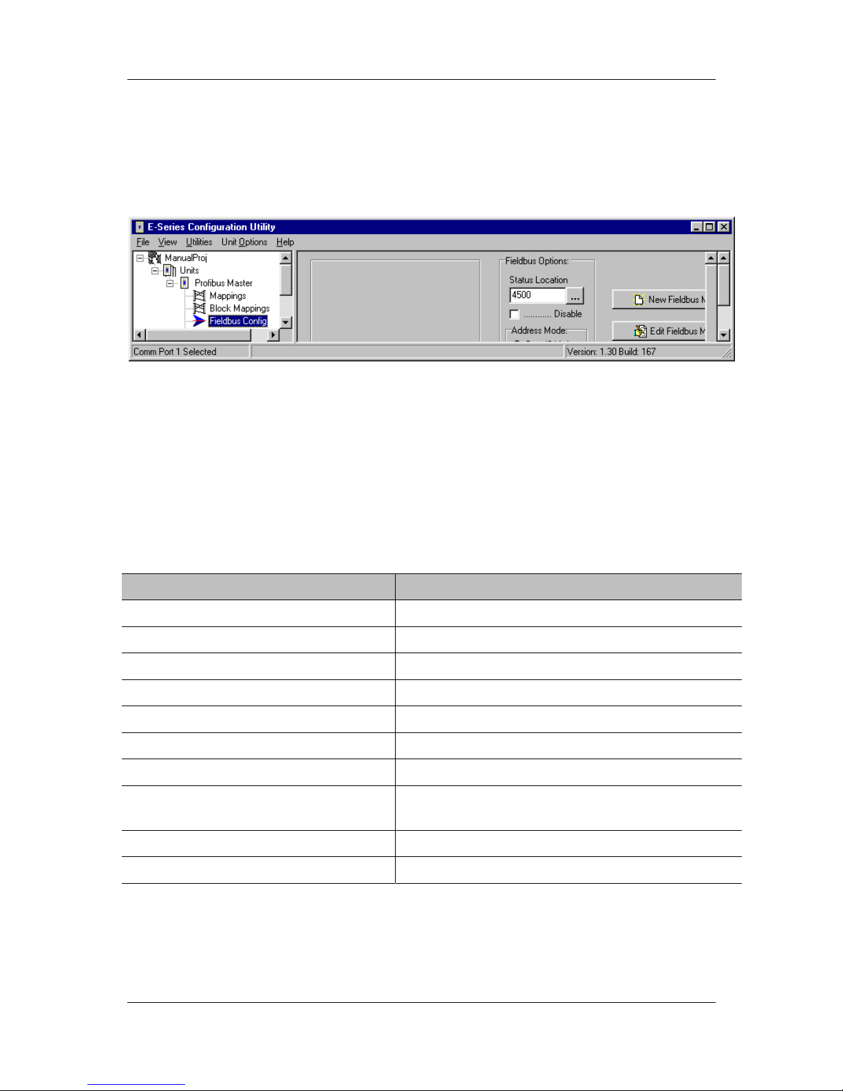
Chapter 4 Configuration
MAN_905G_1.16 Page 92
4.10.4 Message Interface
In addition to cyclic data exchange with slave devices, the 905G Profibus Master also
supports a number of acyclcic services that may be triggered via a special Message Interface.
The message interface is by default disabled, but will become enabled by also enabling a
“Status Location” via the fieldbus configuration tab in configuration software.
The message interface is used to instruct the 905G to perform a specific task, to request data,
to indicate certain events (alarms), or to respond to requests. The message interface can be
controlled via a host or other smart device by constructing the appropriate message in the
Message Interface Area of the 905G I/O Registers (radio interface). Since the message
interface is part of the radio interface, it may be controlled either remotely via appropriate
block mappings (i.e. remote 905G), or locally via a device on the profibus network (i.e.
configuration tool, PLC, or other smart device).
The supported messages are listed in the table below.
Message Description
SET_SLAVE_MODE Send control command to slave(s) (Sync/Freeze)
GET_SLAVE_DIAG Get diagnostic information from a slave
GET_SLAVE_CONFIG Get slave configuration
SET_SLAVE_ADDRESS Set node address of a slave (If supported by slave)
MSAC1_READ acyclic read (class 1)
MSAC1_WRITE acyclic write (class 1)
GET_LIVE_LIST Get information from all nodes on the network
MSAC1_PROFIDRIVE_V3_PARAM_
WRITE
PROFIdrive v.3 acyclic parameter access
MSAL1_ALARM_IND Alarm indication from DPV1 slave
MSAL1_ALARM_CON Confirmation to FB_MSAL1_ALARM_IND

905U-G Wireless Gateway User Manual
Page 93 ©September 2004
The message interface supports the following types of communication:
• Command - Response
A message is sent by the message initiator, and the message recipient is required to
respond. The message initiator can be either the 905G or host device.
• Indication
A message is sent by the message initiator, and no response is required. The message
initiator can be either the 905G or host device.
Message Structure
A message consists of a message header and message data (see table below). The header
consists of a series of 16-bit registers that specifies the type of message and the length of the
message data. The message data may be up to 128 x 16bit registers in length and contain data
that is specific to the particular message.
Offset: Register:
0 Message ID
1 Message Information
2 Command Number
3 Data Size
4 Extended Word 1
5 Extended Word 2
6 Extended Word 3
7 Extended Word 4
8 Extended Word 5
9 Extended Word 6
10 Extended Word 7
11 Extended Word 8
12 Message Data
:::
(up to
139 256 Bytes)
Message ID
The Message ID register contains a 16-bit integer identifier for the command. When a
response is sent back to the message initiator, the same message ID is used in that message.
Message ID’s can be selected arbitrarily, but successive messages must contain different ID’s
so as to trigger the execution of the message (i.e. a message will only be executed upon the
ID value changing).
Header
Data

Chapter 4 Configuration
MAN_905G_1.16 Page 94
Message Information
This register contains information about whether the message is a command or a response,
and may also indicate an error (see below).
b15 b 14 b13 b12 b11 b10 b9 b8 b7 b6 b5 b4 b3 b2 b1 b0
Err C/R(reserved) Error Code Message Type
For example, a command message will always contain the value 4002h in this register. A
response message will contain 0002h, and may contain error information as detailed in the
table below.
Bit/Field Description Contents
Err This bit indicates if the received message
contains any errors
0: Message OK
1: Error
C/R This bit indicates if the message is a
command or a response
0: Response Message
1: Command Message
Error
Code
If the Err bit is set this field contains
additional error information
0h: Invalid Message ID
1h: Invalid Message Type
2h: Invalid Command
3h: Invalid Data Size
4h-6h: Message header malformed
8h: Invalid Response
9h: Flash Config Error
Fh: Invalid Other
(All other values are reserved)
Message
Type
This field specifies the message type 2h: This field must always equal 2.
Command Number
This register contains a 16 bit command identifier, which contains the identifier
corresponding to the exact message command to be executed.
Data Size
This register specifies the size of the Message Data in bytes. The maximum Message Data
size is 256 bytes.
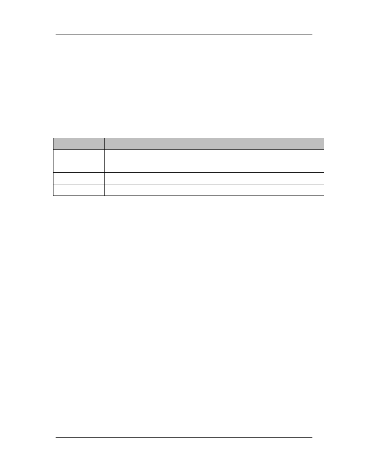
905U-G Wireless Gateway User Manual
Page 95 ©September 2004
Extended Words 1 ... 8
These registers are specific for each command. Consult the specification for each command
for further information.
Message Interface Addressing
Command messages and response messages are allocated fixed locations in the radio
interface (I/O Registers). Also, spontaneously generated alarm messages are allocated unique
fixed locations in the radio interface. The memory allocation of these messages in the radio
interface is outlined in the table below.
I/O Register Purpose
4550 - 4689 Message IN Area (i.e. Messages to send to Profibus Interface)
4700 - 4839 Message OUT Area (i.e. Messages from Profibus Interface)
4850 - 4899 Spontaneous Message OUT Area (i.e. Alarm Messages from Profibus)
4900 – 4949 Spontaneous Alarm ACK IN Area (i.e. ACK to above)
For example, a message could be sent to the Profibus Interface by constructing the required
message in the “Message IN Area”, either via radio using appropriate block mapping(s) or
locally via a host device or configuration tool. This message is activated upon change-of-state
of the Message ID field (see “Message Structure” above). The profibus interface may
generate a response to this message in the “Message OUT Area”, which may then also be
transmitted via radio using appropriate block mappings or locally via the host device.
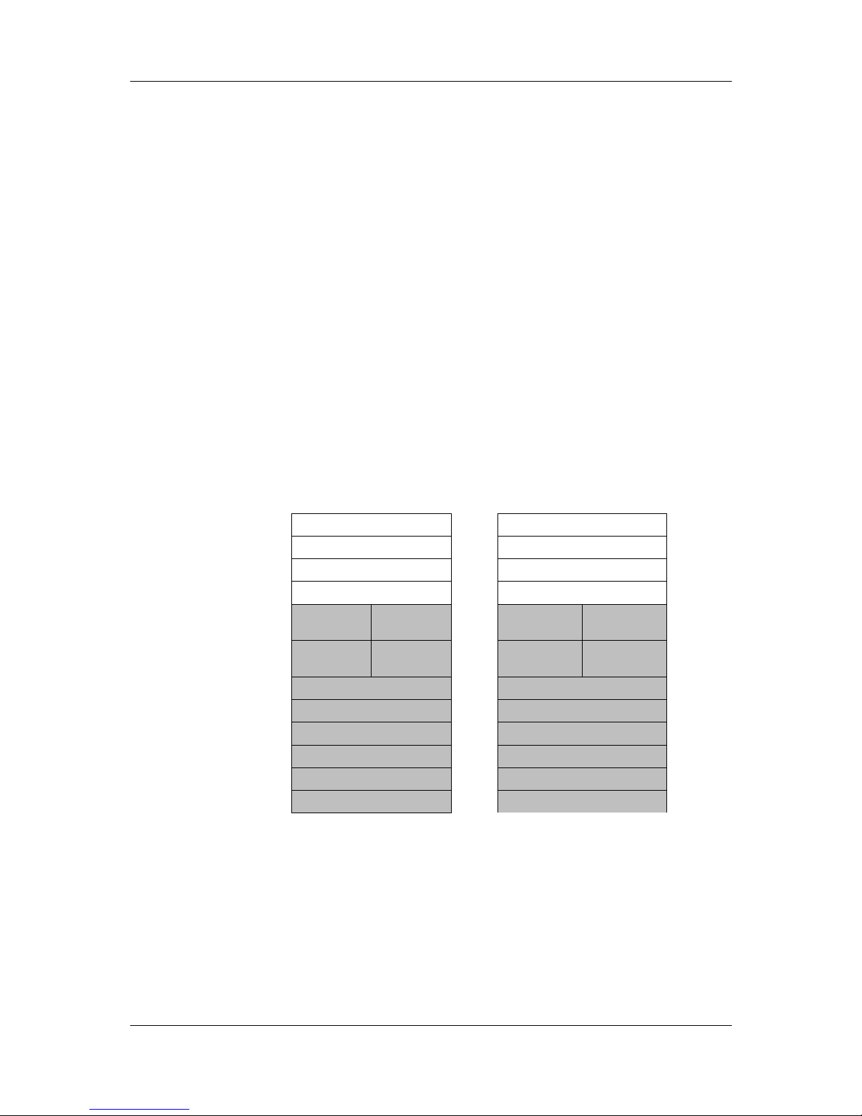
Chapter 4 Configuration
MAN_905G_1.16 Page 96
Set Slave Mode
SET_SLAVE_MODE: Command Number = 0003h.
In addition to station related user data transfer, which is executed automatically, the master
can send control commands to a single slave, a group of slaves or all slaves simultaneously.
These control commands are transmitted as multicast commands. This permits use of sync
and freeze modes for event controlled synchronisation of the slaves.
The slaves begin sync mode when they receive a sync command from their assigned master.
The outputs of all addressed slaves are then frozen in their current state. During subsequent
user data transmissions, the output data are stored at the slaves, but the output states remain
unchanged. The stored output data are not sent to the outputs until the next sync command is
received. Sync mode is concluded with the unsync command.
Similarly, a freeze control command causes the addressed slaves to assume freeze mode. In
this operating mode, the states of the inputs are frozen until the master sends the next freeze
command. Freeze mode is concluded with the unfreeze command.
Note : Not all slaves supports this feature. Consult the documentation for the actual slave for
further information.
Command and response layout:
Command Response
Message ID
(ID) (ID)
Message Information
4002h 0002h
Command Number
0003h 0003h
Data Size
0000h 0000h
Extended Word 1
Slave
Address
Group Select Slave Address Group Select
Extended Word 2
Control
Command
- Control
Command
-
Extended Word 3
- -
Extended Word 4
- -
Extended Word 5
- -
Extended Word 6
- -
Extended Word 7
- Extended Fault Info
Extended Word 8
- Fault Information
• Slave Address
Range 1-125; 127
If the request applies for only one slave, that Slave Address must be entered in the range
1-125. If a slave group is to be addressed, Slave Address should be 127 (Multicast
address).
• Group Select
Range 01h -FFh (Bit coded)
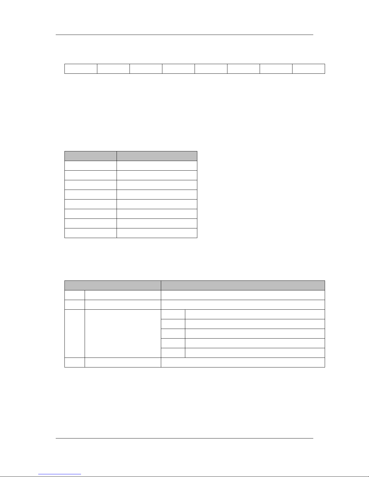
905U-G Wireless Gateway User Manual
Page 97 ©September 2004
This parameter decides which group should be addressed, see below.
bit 7 bit 6 bit 5 bit 4 bit 3 bit 2 bit 1 bit 0
Group 8 Group 7 Group 6 Group 5 Group 4 Group 3 Group 2 Group 1
Example: To address Group 1, 2 and 4, the Group Select value should be 0Dh. If an
individual slave should be addressed the correct group selection must also be made, since
the slave will ignore the message if it does not belong to the requested group(s).
The group(s) a slave belongs to is determined during network configuration with ESeries
Configuration Software, and is downloaded during initialisation to each slave via the
Profibus telegram Set_Prm.
• Control Command
This parameter specifies the command to send.
Bit Explanation
0 (LSB) Reserved (set to zero)
1 Reserved (set to zero)
2 Unfreeze input data
3 Freeze input data
4 Unsynchronize output data
5 Synchronize output data
6 Reserved (set to zero)
7 (MSB) Reserved (set to zero)
• Fault Information &Extended Fault Information
If ‘Invalid Other ’is returned in the Message Information word in the header of the
response, information about the fault can be found here.
‘Fault Information’ contents ‘Extended Fault Information’ contents
0001h Address out of range 0002h Group number 0 not permitted -
000Ah Incorrect operation mode
5001h Invalid Freeze group (Group is not initiated to be Freeze group)
5002h Invalid Sync group (Group is not initiated to be a Sync group)
5003h Incorrect Control Command
000Ah
Failed to send Global Control
request
5004h No Sync-/ or Freeze groups enabled in master configuration.
00FFh Module not initialised -

Chapter 4 Configuration
MAN_905G_1.16 Page 98
Get Slave Diagnostics
GET_SLAVE_DIAG: Command Number = 0004h
This command reads diagnostic data from a specified slave.
Note: The response data size depends on the actual slave implementation. Range 6 -244.
Command and response layout:
Command Response
Message ID
(ID) (ID)
Message Information
4002h 0002h
Command Number
0004h 0004h
Data Size
0000h (Size of data)
Extended Word 1
Slave
Address
Type of
request
Slave Address
Type of
request
Extended Word 2
- -
Extended Word 3
- -
Extended Word 4
- -
Extended Word 5
- -
Extended Word 6
- -
Extended Word 7
- Extended Fault Info
Extended Word 8
- Fault Information
Response data word 1
Station Status1Station Status
2
Response data word 2
Station Status
3
Master
Address
Response data word 3
Ident Number
Response data word 4
:::
Response data word n
Extended Diagnostic Data
• Slave Address
Range 1-125, specifies the slave to read diagnostics from.
• Type of request
0x00: Internal slave diagnostic request. The diagnostic information stored in the master is
returned. Can only be requested for slaves configured by the master.
0x01: External slave diagnostic request. A diagnostic request is sent on the network to the
specified slave. Can be requested for all slaves on the network.
• Station Status [1 ...3 ]
Consult EN50170 Vol.2 for further information.
• Master Address

905U-G Wireless Gateway User Manual
Page 99 ©September 2004
Address of the master that parameterized the slave
• Ident Number
Unique ID assigned by the Profibus User Organization
• Extended Diagnostic Data
Slave user specific diagnostic data. Consult the documentation for the actual slave for
further information.
• Fault Information &Extended Fault Information
If ‘Invalid Other ’is returned in the Message Information word in the header of the
response, information about the fault can be found here.
‘Fault Information’ contents ‘Extended Fault Information’ contents
0001h Address out of range -
0018h
DPMC_M_START has not yet occurred
(DPMC_ERR_M_NOT_ALLOWED)
000Ah
Failed to read Diagnostic Data
from slave
002Bh
Buffer provided by the user is not sufficient.
(DPMC_ERR_M_BLOCK_LEN_INVALID)
00FFh Module not initialised -

Chapter 4 Configuration
MAN_905G_1.16 Page 100
Set Slave Address
SET_SLAVE_ADDRESS: Command Number = 0006h
This command makes it possible to set the node address of a specified slave, provided that
the slave supports this feature.
Note: The message data size depends on the actual slave implementation; range 0 -240 bytes.
Command and response layout:
Command Response
Message ID
(ID) (ID)
Message Information
4002h 0002h
Command Number
0006h 0006h
Data Size
(Size of data) (Size of data)
Extended Word 1
Current
Slave Add
New Slave
Add
Current Slave
Add
New Slave
Add
Extended Word 2
Slave Ident Number Slave Ident Number
Extended Word 3
No_add_Chg -
No_add_
Chg
-
Extended Word 4
- -
Extended Word 5
- Err Code1 Err Code2
Extended Word 6
- Err Code3 Err Code4
Extended Word 7
- Return Code
Extended Word 8
- Fault Information
Message data byte 1
Slave Data 1 Slave Data 1
:::
::: :::
Message data byte n
Slave Data n Slave Data n
• Current Slave Address
Range 1-125, specifies the current address of the slave
• New Slave Address
Range 1-125, specifies the new address of the slave
• Slave Ident Number
Ident number for the slave, whose address should be altered
• No_add_Chg
This parameter specifies whether it is allowed to change the slave address again at a later
stage. If this is not allowed, then it is only possible to change the address with this
function after initial reset. After the initial reset the slave takes the default address 126.

905U-G Wireless Gateway User Manual
Page 101 ©September 2004
00h: Change of address is still possible at a later stage
01h-FFh: Change of address only possible after the initial address (i.e. default address =
126)
• Error Code [1 ...4 ]
If ‘Return Code ’ equals 8030h (‘Negative indication from lower layer ’), status values
according to the DP-specification are available in ‘Error Code 1 ’. Error Codes 2 ...3 are
reserved.
(See "Return Codes" and "Error Codes" in section 4.10.5 below.)
• Return Code
See "Return Codes" in section 4.10.5 “DP Error Codes ”.
• Fault Information
If ‘Invalid Other ’is returned in the Message Information word in the header of the
response, information about the fault can be found here.
0001h: Current slave address out of range.
0002h: New slave address out of range.
000Ah: Failed to execute request.(See ‘Return Code ’ for additional fault information))
000Bh: Remote station failure.(See ‘Return Code ’ for additional fault information)
00FFh: Module not initialised.
• Slave Data
With this parameter it is possible to deliver user specific data. The data is stored in the
slave if possible (i.e. EEPROM, FLASH etc.)

Chapter 4 Configuration
MAN_905G_1.16 Page 102
Get Live List
GET_LIVE_LIST: Command Number = 0018h
This command returns 127 bytes of information about the nodes on the network. Every byte
stands for one bus subscriber, and the position of the byte in the response data assigns the
address
Command and response layout:
Command Response
Message ID
(ID) (ID)
Message Information
4002h 0002h
Command Number
0018h 0018h
Data Size
0000h 007Fh
Extended Word 1
- -
Extended Word 2
- -
Extended Word 3
- -
Extended Word 4
- -
Extended Word 5
- -
Extended Word 6
- -
Extended Word 7
- Return Code
Extended Word 8
- Fault Information
Response data byte 1
Station Type 0
Response data byte 2
Station Type 1
:::
:::
Response data byte 127
Station Type 126
• Station Type [0 ...126]
00h: Slave Station
01h: Master Station not yet ready for Token ring (station only physically at the bus)
02h: Master Station ready to enter Token ring (there is not yet any Token
transmission)
03h: Master Station in Token ring (Token transmission through the station)
04h: Station does not exist
• Fault Information
If ‘Invalid Other ’is returned in the Message Information word in the header of the
response, information about the fault can be found here.
000Ah: Failed to build Live List
00FFh: Module not initialised
 Loading...