

Page 1

User Manual
905U-E Wireless Ethernet Bridge
ELPRO Technologies Pty Ltd, 9/12 Billabong Street, Stafford Q 4053, Australia.
Tel: +61 7 33524533 Fax: +61 7 33524577 Email: [email protected]
Web: www.elprotech.com
Page 2

905U-E Wireless Ethernet Bridge User Manual
Thank you for your selection of the 905U-E Wireless Ethernet Bridge. We trust it will
give you many years of valuable service.
ATTENTION!
Incorrect termination of supply wires may
cause internal damage and will void warranty.
To ensure your 905U-E enjoys a long life,
double check ALL your connections with
the user’s manual
before turning the power on.
Caution!
For continued protection against risk of fire, replace the internal module fuse only with the same type
and rating.
CAUTION:
To comply with FCC RF Exposure requirements in section 1.1310 of the FCC Rules, antennas used
with this device must be installed to provide a separation distance of at least 20 cm from all persons
to satisfy RF exposure compliance.
DO NOT:
operate the transmitter when someone is within 20 cm of the antenna
operate the transmitter unless all RF connectors are secure and any open connectors are properly
terminated.
operate the equipment near electrical blasting caps or in an explosive atmosphere
All equipment must be properly grounded for safe operations. All equipment should be serviced only
by a qualified technician.
Man_905U-E Rev 1.0 Page 2
Page 3

Important Notices
FCC Notice:
This user’s manual is for the ELPRO 905U-E Wireless Ethernet bridge. This device
complies with Part 15.247 of the FCC Rules.
Operation is subject to the following two conditions:
This device may not cause harmful interference and
This device must accept any interference received, including interference that may cause
undesired operation.
This device must be operated as supplied by ELPRO Technologies Pty Ltd. Any changes or
modifications made to the device without the written consent of ELPRO Technologies Pty.
Ltd. May void the user’s authority to operate the device.
This device may only be used with ELPRO antenna / cable combinations as specified
below.
Cable Options ELPRO
No Cable CC10/900 CC20/900
Antenna
Part #
Antenna
Gain
WH900 -2dBi OK N/A N/A
DG900 -2dBi OK N/A N/A
CFD890EL 0dBi OK N/A N/A
SG900EL +5dBi N/A OK OK
SG900-6 +8dBi N/A OK OK
YU6/900 +10dBi N/A
NOT
OK
Permitted
End user products that have this device embedded must be supplied with non-standard
antenna connectors, and antennas available from vendors specified by ELPRO
Technologies. Please contact ELPRO Technologies for end user antenna and connector
recommendations.
Notices:
Safety
Exposure to RF energy is an important safety consideration. The FCC has adopted a safety standard
for human exposure to radio frequency electromagnetic energy emitted by FCC regulated equipment
as a result of its actions in Docket 93-62 and OET Bulletin 65 Edition 97-01.
Limited Warranty, Disclaimer and Limitation of Remedies
ELPRO products are warranted to be free from manufacturing defects for a period of 24 months from
Page 3 © February 2005
Page 4

905U-E Wireless Ethernet Bridge User Manual
the effective date of purchase by the end user. The effective date of purchase is decided solely by
ELPRO Technologies.
This warranty does not extend to:
- failures caused by the operation of the equipment outside the particular product's specification,
or
- use of the module not in accordance with this User Manual, or
- abuse, misuse, neglect or damage by external causes, or
- repairs, alterations, or modifications undertaken other than by an authorized Service Agent.
ELPRO’s liability under this warranty is limited to the replacement or repair of the product. This
warranty is in lieu of and exclusive of all other warranties. This warranty does not indemnify the
purchaser of products for any consequential claim for damages or loss of operations or profits and
ELPRO is not liable for any consequential damages or loss of operations or profits resulting from the
use of these products. ELPRO is not liable for damages, losses, costs, injury or harm incurred as a
consequence of any representations, warranties or conditions made by ELPRO or its representatives or
by any other party, except as expressed solely in this document.
CONTENTS
2.3 P
2.4 E
2.4 S
2.4.1 RS232 Serial Port.......................................................................................................... 6
2.4.2 RS485 Serial Port.......................................................................................................... 7
2.4 D
CHAPTER THREE.................................................................................... OPERATION 9
3.1 P
3.2 S
3.3 A
3.3 B
3.3 R
3.3 A
OWER SUPPLY
THERNET CONNECTIONS
ERIAL CONNECTIONS
IGITAL INPUT/OUTPUT
OWER-UP AND NORMAL OPERATION
ERIAL AND RADIO DATA
DDRESSING
RIDGE MODE
OUTER MODE
CCESS POINT
............................................................................................................... 6
............................................................................................... 6
.................................................................................................... 6
.................................................................................................. 8
............................................................................................... 9
................................................................................................................. 10
.............................................................................................................. 10
............................................................................................................. 10
.............................................................................................................. 11
............................................................................. 9
3.3 C
3.3 F
3.3 R
3.8 R
LIENT
..........................................................................................................................11
ILTER
..........................................................................................................................11
ADIO RATES
ADIO INTERFERENCE
................................................................................................................ 12
................................................................................................... 12
CHAPTER FOUR................................................................................... CONFIGURATION 13
Man_905U-E Rev 1.0 Page 4
Page 5

Important Notices
4.1 B
4.2 A
4.3 D
4.4 C
4.6 C
EFORE CONFIGURING
DDRESSING
EFAULT CONFIGURATION
ONFIGURATION PROGRAM
ONFIGURATION EXAMPLES
................................................................................................................. 13
.................................................................................................. 13
........................................................................................... 13
.......................................................................................... 14
......................................................................................... 25
CHAPTER SIX .................................................................................TROUBLESHOOTING 31
6.1 D
6.1 C
6.1 M
6.1 S
IAGNOSTICS CHART
ONNECTIVITY
ONITOR COMMUNICATIONS
TATISTICS
.............................................................................................................. 31
.................................................................................................................... 32
.................................................................................................... 31
....................................................................................... 31
6.1 PING ............................................................................................................................ 32
6.1 IPCONFIG ................................................................................................................... 32
6.1 ARP..............................................................................................................................32
6.1 ROUTE ........................................................................................................................ 32
Accessing Configuration inside a module for the first time ................................................ 14
Modifying an existing configuration.................................................................................... 19
Remote modification of an existing configuration ..............................................................19
Setting a 905U-E to Factory Default Settings...................................................................... 25
Extending a wired network..................................................................................................26
Connecting two separate networks together........................................................................ 28
Page 5 © February 2005
Page 6

905U-E Wireless Ethernet Bridge User Manual
-
2.3 Power Supply
The 905U-E module is powered by a 10 - 30VDC
supply. The power supply should be rated at 1 Amp and
be CSA Certified Class 2.
The negative side of the supply is connected to "COM"
and may be connected to “ground”. The supply negative
is connected to the “GND” terminal internally. The
positive side of the supply must not be connected to earth. The supply may be a floating supply
or negatively grounded.
The power requirements of the 905U-E units is 700mA at 12VDC or 450mA at 24VDC.
10 – 30 +
VDC -
905U-E
+
2.4 Ethernet Connections
HUB NIC
2.4 Serial Connections
2.4.1 RS232 Serial Port
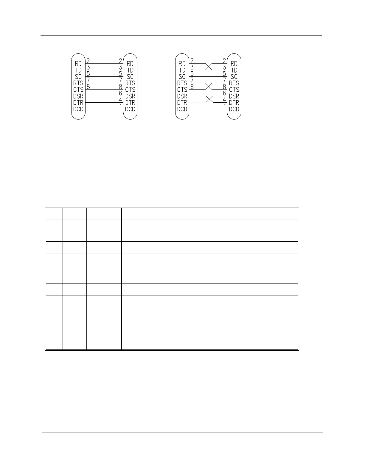
The serial port is a 9 pin DB9 female and provides for connection to a host device. This
port is independent of the RS485 port. Communication is via standard RS232 signals.
The 905U-E is configured as DCE equipment with the pinout detailed below.
Man_905U-E Rev 1.0 Page 6
Page 7
Chapter Two Installation
905U-D
DB9
MALE
DTE HOST
DB9
FEMALE
905U-D
DB9
MALE
DCE HOST
DB9
MALE
Hardware handshaking using the CTS/RTS lines is provided. The CTS/RTS lines may be used to
reflect the status of the local unit’s input buffer, or may be configured to reflect the status of
CTS/RTS lines at the remote site. The 905U-D does not support XON/XOFF.
Example cable drawings for connection to a DTE host (a PC) or another DCE host (or modem) are
detailed above.
DB9 Connector Pinout
Pin Name Direction Function
1 DCD Out
2 RD Out
3 TD In
4 DTR In
5 SG
Data carrier detect –
- on when link is established in controlled mode
- on always in transparent mode
Transmit Data – Serial Data Output
Receive Data – Serial Data Input
Data Terminal Ready - DTR can be configured to initiate low power
mode, or to force a link disconnection (“hang up” in controlled mode.
Signal Ground
6 DSR Out
7 RTS In
8 CTS Out
9 RI
2.4.2 RS485 Serial Port
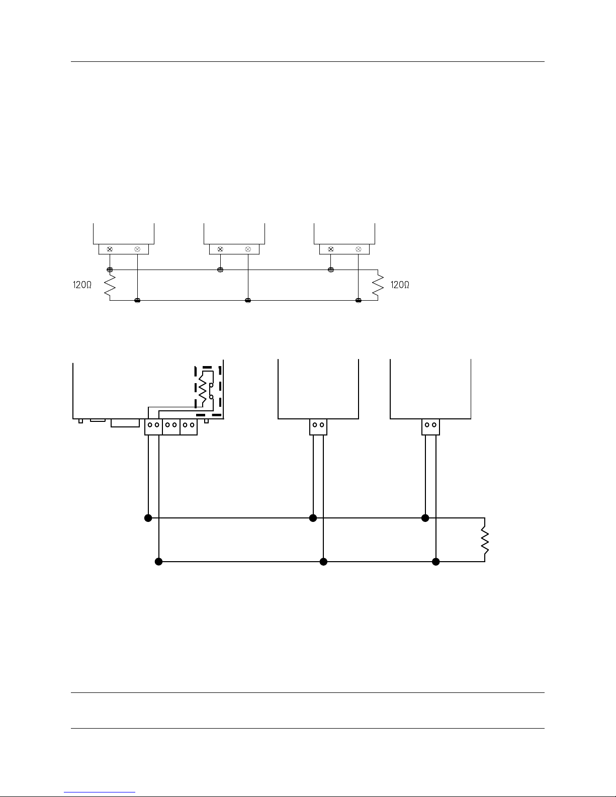
The RS485 port provides for communication between the 905U-E unit and its host device using a
multi-drop cable. Up to 32 devices may be connected in each multi-drop network.
Page 7 © February 2005
Data Set Ready - always high when unit is powered on.
Request to Send - hardware flow control configurable
Clear to send - hardware flow control configurable
Ring indicator - indicates another module is attempting to connect in
controlled mode.
Page 8
905U-E Wireless Ethernet Bridge User Manual
HOST
905U-D
HOST
Ω
RS485
RS485 CONNECTION USING TERMINATING RESISTOR
DEFAULTS DIP SWITCH
As the RS485 communication medium is shared, only one of the units on the RS485 cable may
send data at any one time. Thus communication protocols based on the RS-485 standard require
some type of arbitration.
RS485 is a balanced, differential standard but it is recommended that shielded, twisted pair cable
be used to interconnect modules to reduce potential RFI. It is important to maintain the polarity
of the two RS485 wires. An RS485 network should be wired as indicated in the diagram below
and terminated at each end of the network with a 120 ohm resistor. On-board 120 ohm resistors
are provided and may be engaged by operating the single DIP switch in the end plate next to the
RS485 terminals. The DIP switch should be in the “1” or “on” position to connect the resistor. If
the module is not at one end of the RS485 cable, the switch should be off.
RS485 CONNECTIONS
905U-E
ETHERNET
HOST HOST
120
RS232
SUPPLY
DIO
DIP SWITCH
FOR 120Ω
120
+
+
+
2.4 Digital Input/Output
Man_905U-E Rev 1.0 Page 8
Page 9

Chapter Three Operation
Chapter Three OPERATION
3.1 Power-up and Normal Operation
When power is initially connected to the 905U-E module, the module will perform internal
diagnostics to check its functions. The following table details the status of the indicating LEDs
on the front panel under normal operating conditions.
LED Indicator Condition Meaning
OK On Normal Operation
Radio RX GREEN flash
RED flash
Radio TX Flash Radio Transmitting
Serial RX GREEN flash
RED flash
Serial TX GREEN flash Serial Port Transmitting
LINK On On when a radio communications link is
LINK Off Communications failure or radio link
Other conditions indicating a fault are described in Chapter Six Troubleshooting.
Radio receiving data
Weak radio signal
Serial Port Receiving
CTS low
established
not established
3.2 Ethernet Data
3.2 Serial Data
The 905U-E module provides a full-duplex RS232 serial port and half-duplex RS485 serial port.
The radio communications is half-duplex - this means that the 905U-E operates at half duplex.
Many applications use full duplex RS232 communications but do not require full duplex - the
Page 9 © February 2005
Page 10

905U-E Wireless Ethernet Bridge User Manual
protocol used operates at half-duplex and will operate with the 905U-E without problems. If an
application really requires full duplex communications, then the 905U-E should not be used.
3.2 Radio Data
3.3 Addressing
A 905U-E network comprises modules with the same "system" address. Only modules with the
same system address will communicate with each other. This feature allows more than one
system to operate in the same area on the same radio channel.
3.3 Bridge Mode
Joins sections of the same network.
Work at the MAC Layer.
Filter may be used to minimize traffic
Learns where to send data
Initially Broadcast, listen, then limit
3.3 Router Mode
Joins separate networks
Useful for minimizing traffic between networks
Work at the Internet Layer
Knows where to send data based on IP address and routing rules.
905U-E at present only implements only 1 routing rule – default gateway
Man_905U-E Rev 1.0 Page 10
Page 11

Chapter Three Operation
3.3 Access Point
Access Points (AP)??.
Alternatively, Access Points may be used as a single hop repeater.
All radio traffic with the radio cell is controlled by the Access Point, and must pass through the
Access Point. Ideally the Access Point is placed at the wired location where the majority of data
traffic will flow. This will reduce quantity of data transmitted over the radio.
Access Points periodically sent out Beacon messages. These messages are used by Clients to
synchronise their link with an individual AP.
3.3 Client
A Client is a How is a Connection Established
Client Scanning - RX LED flicker. Select best RSSI
Joining, Timer Synchronisation, Leadin short
Authentication Request
Encryption Requested -> Challenge and Response
Acceptance
Association LINK LED on
Monitor RSSI and Fade Margin
Short vs Long Beacon Interval
How is a Connection Lost
Retry 3 times, allow other data through, backoff, then disassociation
Client hears misses several beacons
Client periodically reassociates
Access Point doesn’t hear any reassociating or data from a Client
All related to Beacon Interval configured.
3.3 Filter
need to add other bridges mac addresses when in bridge mode?
Page 11 © February 2005
Page 12

905U-E Wireless Ethernet Bridge User Manual
3.3 Radio Rates
The 905U-E is capable of using several radio transmission rates. A reduction in speed will
increase the range.
3.8 Radio Interference
The 905U-E operates on the 902-928MHz license-free radio band (restricted to 915 – 928 MHz
in Australia and 921 – 928MHz in New Zealand). Devices on this radio band must use a spread
spectrum technique to allow multiple users to share the band with minimal interference.
The 905U-E uses a frequency-hopping spread spectrum technique. The 905U-E will not interfere,
or be interfered by, radio devices on other bands, such as two way radios or wireless telephones.
There can be interference from other devices on the same band. As the “hopping sequence” used
by the 905U-E is different to other devices on this band, the probability of two devices using the
same channel is small, and if this does occur, the probability of sharing the same channel on a
re-transmission is even smaller.
In countries which allow the full 902-928MHz band (such as USA and Canada), there are eight
hopping sequences, and the first four do not use the same frequency channels as the last four -
this can give isolation between two systems. That is, a system with hopping sequence 1 will
hear messages from another system using hopping sequence 3, but will not if the other system
used hopping sequence 5. The hopping sequence may be configured under the Radio Settings
Configuration menu. In countries which only allow half the band (such as Australia and New
Zealand), it is not possible to separate systems in this way because the band is smaller and all
hopping sequences use all channels available.
Man_905U-E Rev 1.0 Page 12
Page 13

Chapter Five Specifications
Chapter Four CONFIGURATION
4.1 Before Configuring
Configuration comprises selecting parameter values for the operation of the 905U-E unit. Before
you start configuration, parameter settings must be decided. The main parameters are:-
• Addressing – System address, IP address, Network mask, Gateway IP address.
• Device Mode – Bridge or Router
• Operating Mode – Access Point or Client.
• Encryption
The other configuration parameters do not need to be selected, and are provided as a means of
"fine tuning" the operation of the 905U-E units.
Configuration may be achieved using only Windows Internet Explorer ®.
4.2 Addressing
A 905U-E network comprises modules with the same "system" address. The system address is
text string 1 to 31 characters in length. Only modules with the same system address will
communicate with each other. If you are adding another module to an existing system, use the
same value as the existing modules. If you are starting a new system, select random values and
use the same value for each module.
The Device Mode must also be selected. If you wish to link a single network together, then set
Device Mode to Bridge. If two separate networks are to be joined then Device Mode should be
set to Router.
IP addresses and netmasks must be set to reflect the Device Mode configured. If the unit is
configured as a Router, then the 905U-E requires an IP address and netmask to be set for within
each of the networks it is joining. When configured as a Bridge, the 905U-E requires only one IP
address.
4.3 Default Configuration
The default configuration of the 905U-E is a Bridge, Client, IP address 192.168.123.123,
netmask 255.255.255.0, gateway IP address 192.168.123.1. Default username is “user” and the
default password is “user” for configuration.
The module may be forced to factory default setting by using the default configuration dipswitch
or via the System Tools menu via Internet Explorer.
Page 13 © February 2005
Page 14

905U-E Wireless Ethernet Bridge User Manual
4.4 Factory Default Switch
When powered up with the Factory Default switch on, the 905U-E will start with temporary
settings of ethernet IP address 192.168.123.123, subnet mask 255.255.255.0, gateway IP
192.168.123.1, username and password “user” and the radio disabled. This allows easy access to
configuration when configuration detail has been forgotten. The existing configuration is not
modified, unless the user makes changes.
Do not forget to set the switch back to the OFF position and cycle power at the conclusion of
configuration for resumption of normal operation.
4.4 Configuration Program
The 905U-E has a built-in webserver, containing webpages for analysis and modification of
configuration. The configuration must be accessed using Microsoft® Internet Explorer. This
program is shipped with Microsoft Windows or may be obtained freely via the Microsoft®
website on the internet.
Serial configuration for IP address, gateway address and subnet mask may be accessed via the
RS-232 serial port.
Accessing Configuration inside a module for the first time
There are two methods for accessing the configuration inside a 905U-E. The first method
requires changing your computer settings so that the configuring PC is on the same network as
the 905U-E with factory default settings.The second method requires setting an IP address so the
905U-E is accessable on your network.
You will need a straight through ethernet cable between the PC ethernet card and the 905U-E.
The factory default ethernet address for the 905U-E is 192.168.123.123.
Consult your network administrator for an IP address on your network, the gateway IP address,
and network mask.
Adjust PC or 905U-E network settings so that both are on the same network. This may achieved
two ways as outlined below.
Option 1 – Set PC to same network as 905U-E
Connect ethernet cable between unit and the PC configuring the module.
Set the Factory Default Switch to the ON (SETUP) position. This will always start the
905U-E with ethernet IP address 192.168.123.123, subnet mask 255.255.255.0,
gateway IP 192.168.123.1 and the radio disabled. Do not forget to set the switch
back to the OFF position and cycle power at the conclusion of configuration for
resumption of normal operation.
Power up module.
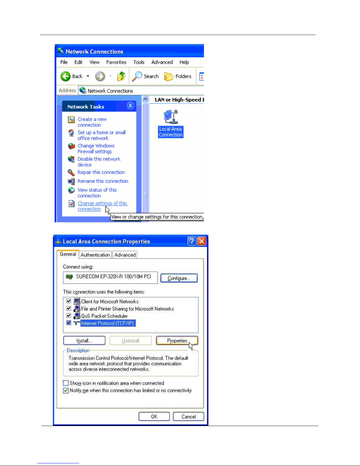
Open Network Settings on PC under Control Panel.
Open Properties of Local Area Connection.
Man_905U-E Rev 1.0 Page 14
Page 15
Chapter Five Specifications
Select Internet Protocol (TCP/IP) and click on Properties.
Page 15 © February 2005
Page 16
905U-E Wireless Ethernet Bridge User Manual
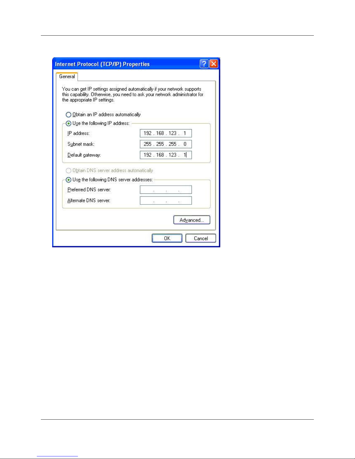
On the General tab enter IP address 192.168.123.1, Subnet mask 255.255.255.0,
and default gateway 192.168.123.1.
Open Internet Explorer and ensure that settings will allow you to connect to the IP
address selected. If the PC uses a proxy server, ensure that Internet Explorer will
bypass the Proxy Server for local addresses. This option may be modified by
opening Tools -> Internet Options -> Connections Tab -> LAN Settings->Proxy
Server -> bypass proxy for local addresses.
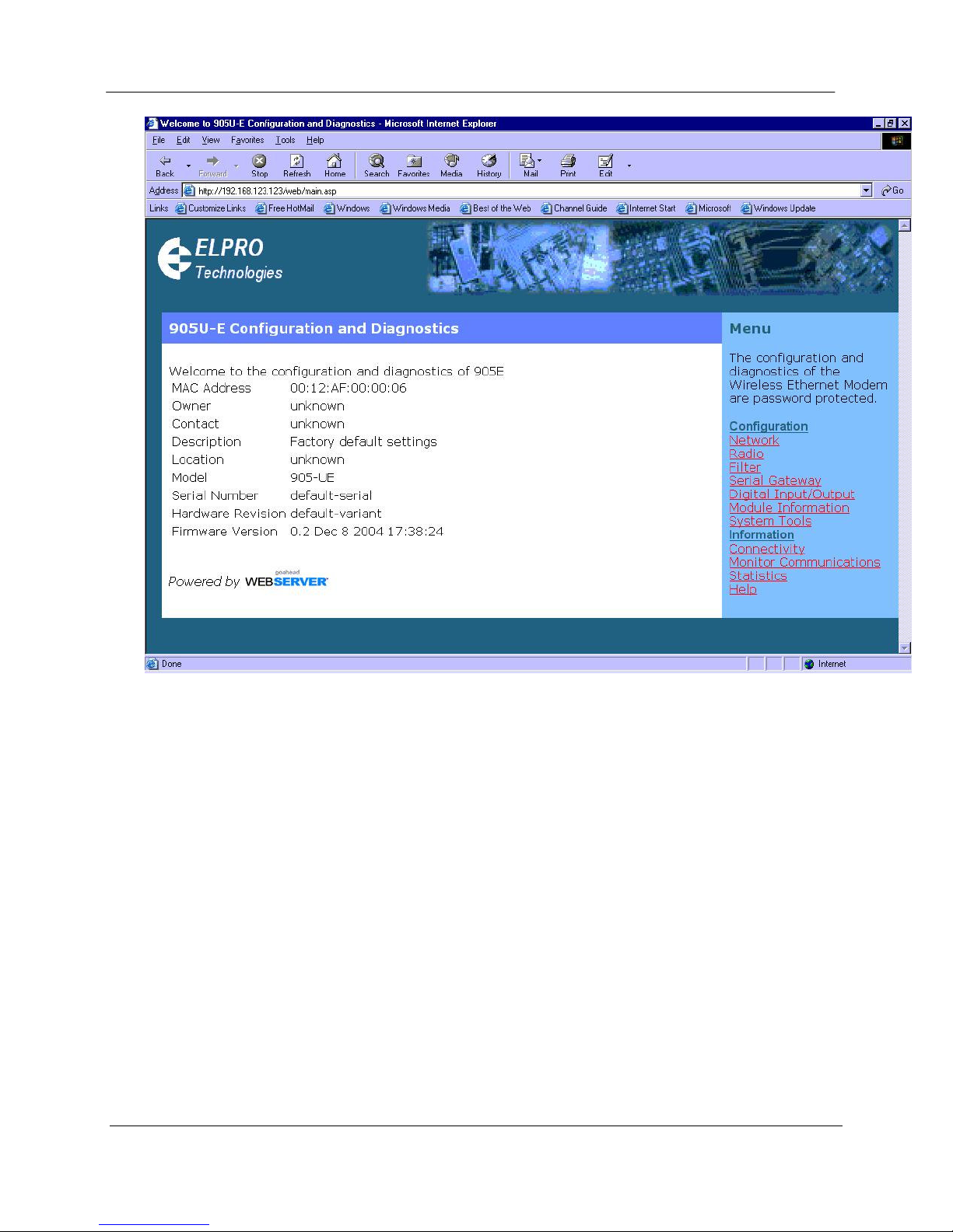
Enter the webpage http://192.168.123.123/ A welcome webpage should be
displayed as illustrated below.
Man_905U-E Rev 1.0 Page 16
Page 17
Chapter Five Specifications
Configuration and Diagnostics may be opened by clicking on any of the menu items,
and entering the default username “user” and password “user”.
Switch dip-switch on 905U-E to RUN (OFF) position, and cycle power to resume
normal configured operation.
Option 2 – Set 905UE to same network as PC
a) Switch dip-switch on 905U-E to SETUP (ON) position.
b) Open a terminal package with 19200bps data rate, 8 data bit, 1 stop and no parity.
c) Power up 905U-E. Basic network settings will be displayed on the terminal as illustrated
below. When prompted, hit enter key to stop automatic boot process.
Page 17 © February 2005
Page 18

905U-E Wireless Ethernet Bridge User Manual
My Right Boot 2.1
Copyright 1999-2004 Cybertec Pty Ltd, All rights reserved.
This software is provided by Cybertec ``as is'' and with NO WARRANTY.
http://www.cybertec.com.au/
ROM : 256KB @ 0xffe00000
RAM : 8192KB @ 0x00000000 (140KB / 0x00023214)
ROM Configuration table ... PASSED.
RAM address pattern check . PASSED.
RAM address bus check ..... PASSED.
Product : E900P
Variant : default-variant
Serial No. : default-serial
Release : default-release
Released date :
Released host :
Build date : Oct 12 2004, 17:27:32
Build host :
Boot Flags : no RAM test, no ROM test, bus timer on, wdog on
static IP, auto-boot, net-boot, reset on
local file, no binary load
Boot delay : 1
Boot Filename : /memory/0xffe40000,0x50000
Boot Address : 169.254.101.93
Boot Netmask : 255.255.255.0
Boot Gateway : 169.254.101.1
Boot Host : 169.254.101.1
Boot Mac 0 : 00:12:af:00:00:04
RTE data store .... no error
Setting bus timer (on) and watchdog (on) ... PASSED
eip: mount point /memory
fec0: connected at 10M Half Duplex.
fec0: local ip = 169.254.101.93, server ip = 169.254.101.1
Press ENTER to abort automatic booting ... 30
d) Check values for Boot Address, Boot Netmask, and Boot Gateway. These values should
be set to reflect those of the PC you are using to configure the unit. If these are correct
skip to step (h). You may check settings again with the rct command. For further help,
type the help command.
e) Set Boot Netmask to the same settings as the computer you have the ethernet cable
connected to. This may be performed with the command: bnm <Type the netmask>
f) Set Boot Gateway to the same settings as the computer you have the ethernet cable
connected to. This may be performed with the command: bgw <Type the gateway IP
address>
g) Choose an IP address for the 905U-E being upgraded. This IP address must be on the
same network as the computer you have connected the ethernet cable to. This may be
performed with the command: bip <Type the IP address>
h) Set boot delay to 1 second with the command bdelay 1
i) Switch dip-switch on 905U-E to RUN (OFF) position.
j) Type the command reset. The 905UE will reset and start with the network settings you
have entered.
Man_905U-E Rev 1.0 Page 18
Page 19

Chapter Five Specifications
k) Open Internet Explorer and ensure that settings will allow you to connect to the IP
address selected. If the PC uses a proxy server, ensure that Internet Explorer will bypass
the Proxy Server for local addresses. This option may be modified by opening Tools ->
Internet Options -> Connections Tab -> LAN Settings->Proxy Server -> bypass proxy for
local addresses.
l) Enter the webpage http://xxx.xxx.xxx.xxx/ where xxx.xxx.xxx.xxx is the IP address selected
for the module. A welcome webpage should be displayed as illustrated.
m) Clicking on any of the menu items, and entering the default username “user” and
password “user” may open Configuration and Diagnostics. If the password has previously
been configured other than the default password, then enter this instead.
Modifying an existing configuration
Open Internet Explorer to the IP address set for the module (ie http://xxx.xxx.xxx.xxx/ where
xxx.xxx.xxx.xxx is the IP address set on the 905U-E.), and use menu system to open the item
you wish to modify. When prompted for username and password, enter “user” as the username,
and the previously configured password in the password field.
If IP address or password has been forgotten, the Factory Default switch may be used to access
the existing configuration. Refer to Option 1 Accessing Configuration inside a module for the
first time.
Remote modification of an existing configuration
Care must be taken if modifying the configuration of a module remotely. If the network link is
via a radio link, some changes made may cause loss of the radio link, and therefore the network
connection.
It is advisable to determine path of the links to the modules you wish to modify, and draw a tree
diagram if necessary. Modify the modules at the “leaves” of your tree diagram. These will be the
furtherest away from your connection point in terms of the number of radio or ethernet links.
In a simple system, this usually means modifying the Client modules first and the Access Point
last.
Network Settings Webpage Fields
Device Mode Used to select Bridge or Router mode.
By default this is set to Bridge.
Operating Mode Used to select Access Point or Client mode.
By default this is set to Client.
Bridge Priority The priority of the 905U-E, if configured as a bridge, in the Bridge
FTP Enabled Check this item to enable the FTP server on the 905U-E. The FTP
Page 19 © February 2005
Spanning Tree algorithm.
By default this is set to the lowest priority at 255.
Page 20

905U-E Wireless Ethernet Bridge User Manual
server is not secure, and should be disabled for normal operation of
the unit.
By default this is enabled.
MAC Address This is the unique hardware address of the 905U-E. This item is for
information purposes only.
This unique identifier is assigned to the 905U-E when built in the
factory.
Gateway IP Address The IP address of the default gateway.
By default this is set to 192.168.123.1.
Ethernet IP Address The IP address of the 905U-E on the RJ-45 ethernet port.
By default this is set to 192.168.123.123.
Ethernet IP Subnet Mask The IP network mask of the 905U-E on the RJ-45 ethernet port.
By default this is set to 255.255.255.0.
Wireless IP Address The IP address of the 905U-E on the radio port. If the unit is
configured as a bridge this address must be the same as the ethernet
IP address. If configured as a router, the IP address must be different
from the Ethernet IP Address.
By default this is set to 192.168.123.123.
Wireless IP Subnet Mask The network mask of the 905U-E on the radio port. If configured as
a Bridge, this must be the same as the Ethernet IP Subnet Mask.
By default this is set to 255.255.255.0.
System Address This field must be the same value for all 905U-E intended to interact
with each other using the radio. All units intended to operate within
the same radio cell must have the same system address configured.
By default System Address is set to “905E”.
Radio Encryption
Enabled
Check this field to enable encryption of data transmitted over the
radio.
By default Radio Encryption is disabled.
Encryption Keys 1 to 4 These are the keys used to encrypt radio data to protect data from
unwanted eavesdroppers. These keys must be set the same for all
905U-E intended to operate in the radio cell. Each of the fields are 5
bytes in length, and must be entered as hexidecimal numbers
separated by colons. Eg 12:AB:EF:00:56
Encryption keys must not be all zeros, ie 00:00:00:00:00
Save and Reboot. Save settings to non-volatile memory, and reboot 905U-E.
Man_905U-E Rev 1.0 Page 20
Page 21

Chapter Five Specifications
Radio Settings Webpage Fields
Power Level The transmitter power level desired in mW.
By default this is set to maximum power of 1 Watt.
Data Rate The radio baud rate in bits per second (bps). Available rates are
19200, 57600, 115200, 230400bps and auto.
By default, this is set as auto.
Fade Margin When automatic rate is selected, the 905U-E chooses a rate based on
the received signal strength of transmissions. The value nominated
by the Fade Margin, is subtracted from this average of RSSI and then
used to decide which rate to transmit at. A higher value in Fade
Margin will decrease the threshold in signal strength used to switch
down rates.
By default this is set to 10 dB.
Dwell Time The amount of time, in milliseconds, the 905U-E remains on a
particular frequency whilst frequency hopping. This parameter may
be modified in the event of severe interference to smaller periods of
time. This also has an impact on the maximum size of Fragmentation
Threshold that may be configured.
By default this is set to 400 milliseconds.
Beacon Period This interval is the period between beacon transmissions sent by an
Access Point. The Beacon Interval is also related to the scan period
on a Station. ??Reassociation interval is ?? times the Beacon Interval
Units will timeout after ?? times the Beacon Interval if no response
is heard.
Refer to ?? for more information.
By default this is set to 20 seconds.
Frequency Hopset If configured as an Access Point, the unit will use the value
nominated in Frequency Hopset to select which pseudo-random
frequency hopping sequence to use. Clients automatically adujst
their Frequency Hopset to synchronise with the selected Access
Point.
Frequency Hop Pattern This feature is not implemented in the beta release. This option
Page 21 © February 2005
By default this is set to 0.
allows modifies the selected hopset pattern, to produce a larger
number of effective hopsets.
By default this is set to 0.
Page 22

905U-E Wireless Ethernet Bridge User Manual
E,
Fragmentation Threshold The maximum transmission unit (MTU) of data over the radio. This
selects the maximum number of bytes that will be transmitted in one
message. If more than this number of bytes is input into the 905Uthe module will transmit more than one message.
By default this level is set to 500 bytes
RSSI Threshold The received signal strength level at which beacons from Access
Points are to be ignored. This prevents Clients from establishing
links to Access Points beyond a sustainable range.
By default this level is set below the noise floor at -150 dBm.
Apply Changes Update settings in RAM.
Apply Changes and Save Update settings in RAM and save to non-volatile memory.
Filter Webpage Fields
Add Entries Enter the MAC addresses of devices to be added to the list. Multiple
entries must be separated by a semi-colon.
Delete Entries Check the box alongside entries selected for removal from the list.
Whitelist or Blacklist Uncheck the box to make the list a blacklist. This will ban all
devices with a MAC address in the list from communicating with the
905U-E or utilising the radio link.
Check the box to make the list a whitelist. This will only alow
devices with the MAC addresses listed to communicate with 905U-E
and utilise the radio link. All other devices are banned from
accessing the 905U-E and utilising the radio link. CAUTION: It is
important to add the MAC Address of the configuration PC
when creating a whitelist. If the configuration PC is not on the
whitelist, it will be unable to communicate with the 905U-E for
further configuration. It is advisable to use the Apply Changes
button to test the configuration entered. Once the configuration
is determined to be correct, the Apply Changes and Save button
should be used. In the event that the configuration is incorrect,
a power reset will revert the unit to previously saved
configuration.
Apply Changes Update settings in RAM.
Apply Changes and Save Update settings in RAM and save to non-volatile memory.
Serial Gateway Webpage Fields
This feature is not implemented in the beta release.
Man_905U-E Rev 1.0 Page 22
Page 23

Chapter Five Specifications
Enable Tick to enable serial gateway access.
Data Rate Select serial data rate
Data-Parity-Stop bits Data bit – Parity – Stop bits
Flow Control Enable hardware flow control
Character Timeout Packets are transmitted once a ?? bytes have reached or there have
been no characters received on the serial port for the time nominated
in Character Timeout.
Listen Port The port address on which the 905U-E is to listen for a socket.
Send IP Address The IP address to which the 905U-E is to attempt to connect the
serial port to.
Send Port The port address to which the 905U-E is to attempt to connect the
serial port to.
Apply Changes Update settings in RAM.
Apply Changes and Save Update settings in RAM and save to non-volatile memory.
Module Information Webpage Fields
This configuration page is primarily for information purposes. With the exception of the
password, the information entered here is displayed on the root webpage of the 905U-E.
Password Configuration password. When changing the password on this
screen, it will be sent unencrypted over any wired network. If
encryption is enabled on the 905U-E, any radio communications are
encrypted, and therefore hidden from radio eavesdroppers. Caution
must only be taken if there are potential eavedroppers on the wired
network.
Device Name A text field for a nickname of the particular 905U-E.
Owner A text field for owner name.
Contact A text field for owner phone number, email address etc.
Description A text field used for a description of the purpose of the unit.
Location A text field used to describe the location of the 905U-E.
Page 23 © February 2005
Page 24

905U-E Wireless Ethernet Bridge User Manual
Man_905U-E Rev 1.0 Page 24
Page 25

Chapter Five Specifications
4.6 Configuration Examples
Setting a 905U-E to Factory Default Settings
1. Access configuration webpages of 905U-E. Refer section Accessing Configuration inside a
module for the first time, or Modifying an existing configuration.
2. Click on System Tools Menu Item
3. Enter username “user” and password “user”, when prompted for password.
4. Click on Factory Default Configuration Reset, and wait for unit to reset. When reset, the
LINK LED will flash.
Page 25 © February 2005
Page 26
905U-E Wireless Ethernet Bridge User Manual
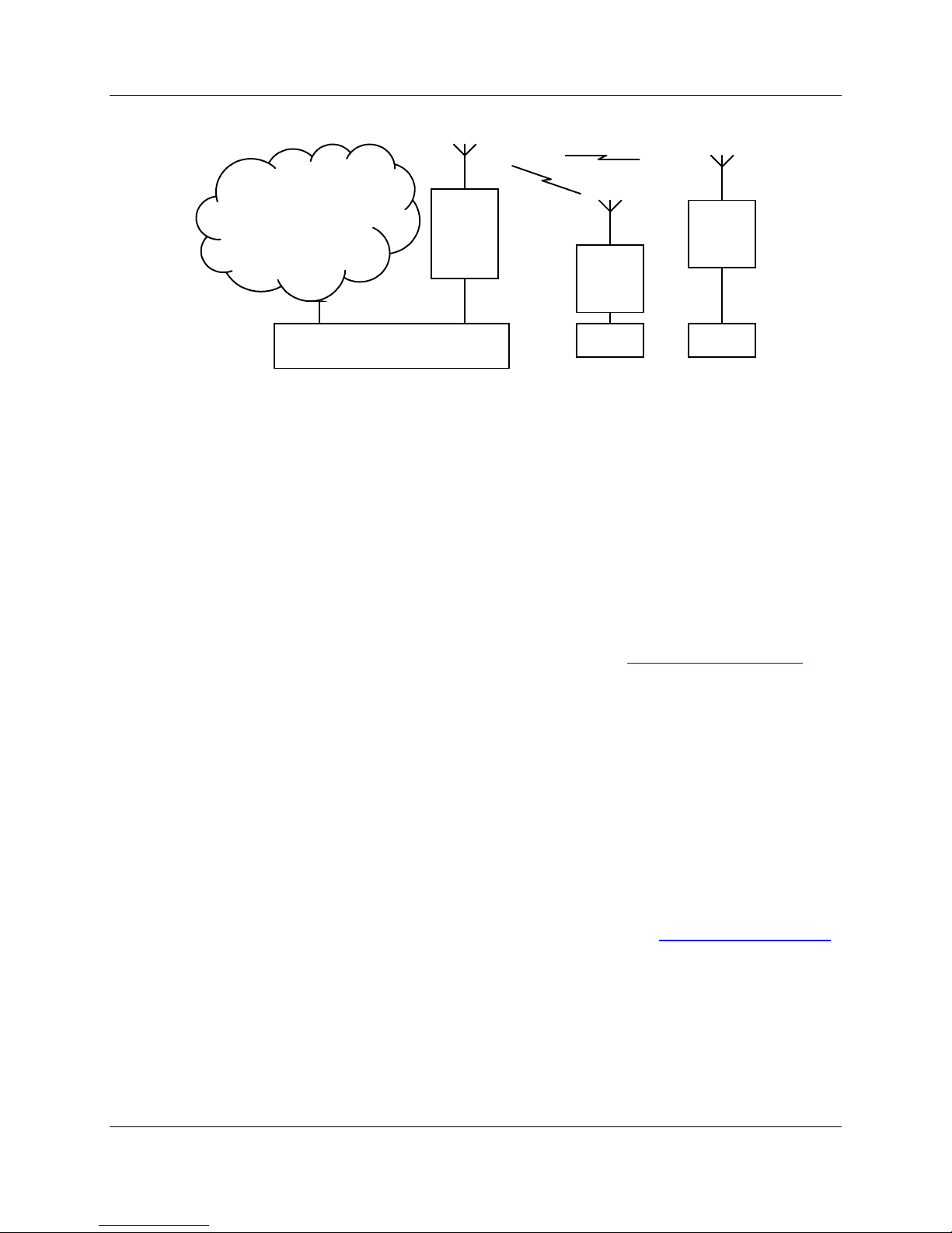
Extending a wired network
Existing Ethernet
Network
192.168.0.0
255.255.255.0
905U-E
Access
Point,
Bridge
905U-E
Client 1,
Bridge
905U-E
Client 2,
Bridge
Ethernet HUB / SWITCH
PLC
PLC
Access Point Configuration
1. Connect straight through ethernet cable between PC and 905U-E.
2. Ensure configuration PC and 905U-E are setup to communicate on the same network
3. Set 905U-E to start with factory default settings. Refer to section Setting a 905U-E to
Factory Default Settings.
4. Power up unit, and wait for LINK led to cease flashing.
Option A – Adjust PC network settings
a) Set Configuration PC network card with network setting of IP address 192.168.123.1,
netmask 255.255.255.0
b) Open configuration webpage with Internet Explorer at address http://192.168.123.123/
Option B – Adjust 905U-E network settings (assuming configuration PC is on existing network)
Open terminal program with settings with data rate 19200bps, 8 data bits, 1 stop bit
and no parity.
Connect straight through serial cable to 905U-E and power up unit.
When prompted, strike the Enter key to abort automatic boot
Set IP address of 905U-E to 192.168.0.200 with command bip 192.168.0.200
Set netmask of 905U-E to 192.168.0.200 with command bnm 255.255.255.0
Set gateway address of 905U-E to 192.168.0.1 with command bgw 192.168.0.1
Reset 905U-E with reset command.
Open configuration webpage with Internet Explorer at address http://192.168.0.200/
5. Click on Network settings menu option.
6. When prompted for password, enter default username “user” and password “user”
7. Set the Operating Mode to Access Point
8. Device Mode should be set to Bridge.
9. Set the Gateway IP address to 192.168.0.1
Man_905U-E Rev 1.0 Page 26
Page 27

Chapter Five Specifications
10. Set the Ethernet IP address to 192.168.0.200, network mask 255.255.255.0
11. Set the Wireless IP address to 192.168.0.200, network mask 255.255.255.0
12. Set the system address to “ExampleSystem1”
13. Enable Radio Encryption and enter key 1 as 01:02:03:04:05, key 2 as 06:07:08:09:0A, key 3
as 0B:0C:0D:0E:0F, key 4 as 10:11:12:13:14.
14. Click on button Save to Flash and Reset. Webpage will display that message indicating
details are being written to flash. Wait for 905U-E to reboot before removing power.
Client 1 Configuration
Perform the same configuration steps as the Access Point configuration with the following
differences:
• At step 0 in Option B, set IP address of 905U-E to 192.168.0.201 with command bip
192.168.0.201
• At step 0 in Option B, open configuration webpage with Internet Explorer at address
http://192.168.0.201/
• At step 7, set the Operating Mode to Client.
• At step 10, set the Ethernet IP address to 192.168.0.201, network mask 255.255.255.0
• At step 11, set the Wireless IP address to 192.168.0.201, network mask 255.255.255.0
Client 2 Configuration
Perform the same configuration steps as the Access Point configuration with the following
differences:
• At step 0 in Option B, set IP address of 905U-E to 192.168.0.202 with command bip
192.168.0.202
• At step 0 in Option B, open configuration webpage with Internet Explorer at address
http://192.168.0.202/
• At step 7, set the Operating Mode to Client.
• At step 10, set the Ethernet IP address to 192.168.0.202, network mask 255.255.255.0
• At step 11, set the Wireless IP address to 192.168.0.202, network mask 255.255.255.0
Page 27 © February 2005
Page 28
905U-E Wireless Ethernet Bridge User Manual
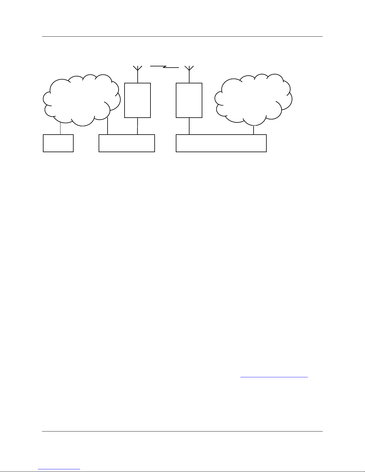
Connecting two separate networks together
Network A
192.168.0.0
255.255.255.0
905U-E
Access
Point,
Router
Ethernet HUB /
SWITCH
905U-E
Client,
Bridge
Ethernet HUB / SWITCHInternet
Network B
192.168.50.0
255.255.255.0
Network A Configuration
In this example, network A is connected to the internet via a router at IP address 192.168.0.1.
Devices on Network A that only require access to devices on Networks A and B, should have
their gateway IP address set to the 905U-E Access Point as 192.168.0.200.
Devices on Network A, that must interact with devices on Networks A and B and the internet
must have routing rules established. On PCs, this may be achieved with the MS-DOS command
ROUTE. For this example use: ROUTE ADD 192.168.0.50.0 MASK 255.255.255.0
192.168.0.200
Network B Configuration
All devices on Network B should be configured so their gateway IP address is that of the 905U-E
Access Point as 192,168.50.200.
Access Point Configuration
1. Connect straight through ethernet cable between PC and 905U-E.
2. Ensure configuration PC and 905U-E are setup to communicate on the same network
3. Set 905U-E to start with factory default settings. Refer to Setting a 905U-E to Factory
Default Settings.
4. Power up unit, and wait for LINK led to cease flashing.
Option A – Adjust PC network settings
Set Configuration PC network card with network setting of IP address
192.168.123.1, netmask 255.255.255.0
a) Open configuration webpage with Internet Explorer at address http://192.168.123.123/
Option B – Adjust 905U-E network settings (assuming configuration PC is on network A)
Open terminal program with settings with data rate 19200bps, 8 data bits, 1 stop bit
and no parity.
Connect straight through serial cable to 905U-E and power up unit.
When prompted, strike the Enter key to abort automatic boot
Man_905U-E Rev 1.0 Page 28
Page 29

Chapter Five Specifications
Set IP address of 905U-E to 192.168.0.200 with command bip 192.168.0.200
Set netmask of 905U-E to 192.168.0.200 with command bnm 255.255.255.0
Set gateway address of 905U-E to 192.168.0.1 with command bgw 192.168.0.1
Reset 905U-E with reset command.
Open configuration webpage with Internet Explorer at address http://192.168.0.200/
5. Click on Network settings menu option.
6. When prompted for password, enter default username “user” and password “user”
7. Set the Operating Mode to Access Point
8. Device Mode should be set to Router.
9. Set the Gateway IP address to 192.168.0.1
10. Set the Ethernet IP address to 192.168.0.200, network mask 255.255.255.0
11. Set the Wireless IP address to 192.168.50.200, network mask 255.255.255.0
12. Set the system address to “ExampleSystem1”
13. Enable Radio Encryption and enter key 1 as 01:02:03:04:05, key 2 as 06:07:08:09:0A, key 3
as 0B:0C:0D:0E:0F, key 4 as 10:11:12:13:14.
14. Click on button Save to Flash and Reset. Webpage will display that message indicating
details are being written to flash. Wait for 905U-E to reboot before removing power.
Client Configuration
Perform the same configuration steps as the Access Point configuration with the following
differences:
• At step 0 in Option B, set IP address of 905U-E to 192.168.0.201 with command bip
192.168.0.201
• At step 0 in Option B, open configuration webpage with Internet Explorer at address
http://192.168.0.201/
• At step 7, set the Operating Mode to Client.
• At step 8, set Device Mode to Bridge.
• At step 9, set the Gateway IP address to 192.168.50.200
• At step 10, set the Ethernet IP address to 192.168.50.201, network mask 255.255.255.0
• At step 11, set the Wireless IP address to 192.168.50.201, network mask 255.255.255.0
Page 29 © February 2005
Page 30
905U-E Wireless Ethernet Bridge User Manual
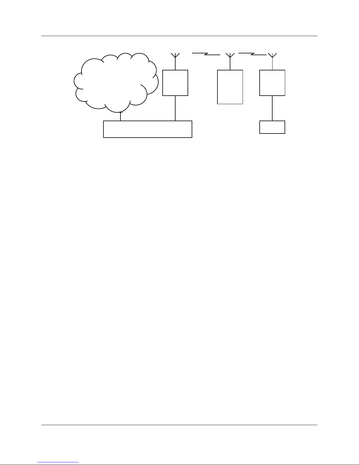
Extending range of a network with a Store and Forward hop
Existing Ethernet
Network
192.168.0.0
255.255.255.0
905U-E
Client 1,
Bridge
905U-E
Access
Point,
Bridge
905U-E
Client 2,
Bridge
Ethernet HUB / SWITCH
PLC
Configure units as described in Section Extending a wired network. Place the Access Point at the
remote intermediate store and forward location.
Man_905U-E Rev 1.0 Page 30
Page 31

Appendix A Hayes Commands
Chapter Six TROUBLESHOOTING
6.1 Diagnostics Chart
INDICATOR CONDITION MEANING
OK LED OFF Continuously
OK LED ON Continuously
Radio TX LED ON Flashes briefly
Radio RX LED ON GREEN flash
RED flash
Serial RX LED ON GREEN flash
RED flash
Serial TX LED ON Flashes briefly
LINK LED ON Continuously
The green OK LED on the front panel indicates correct operation of the unit. This LED
extinguishes on failure as described above. When the OK LED extinguishes shutdown state is
indicated. On processor failure, or on failure during startup diagnostics, the unit shuts down, and
remains in shutdown until the fault is rectified.
• Power supply failure
• CPU failure
• Normal Operation
• Radio transmitting
• Radio receiving data
• Weak radio signal (< -95dBm)
• Serial Port Receiving
• Input buffer almost full
• Serial port transmitting
• A radio link has been
established.
6.1 Connectivity
6.1 Monitor Communications
Page 31 © February 2005
Page 32

905U-E Wireless Ethernet Bridge User Manual
6.1 Statistics
6.1 PING
6.1 IPCONFIG
6.1 ARP
6.1 ROUTE
Man_905U-E Rev 1.0 Page 32
Page 33

Appendix A Hayes Commands
Chapter Six GLOSSARY
ACK Acknowledgment.
Access point An access point is the connection that ties wireless communication devices
into a network. Also known as a base station, the access point is usually
connected to a wired network.
Antenna Gain Antennae don't increase the transmission power, but focus the signal more.
So instead of transmitting in every direction (including the sky and ground)
antenna focus the signal usually either more horizontally or in one
particular direction. This gain is measured in decibels
Bandwidth The amount of "transportation" space an Internet user has at any given
time.
Bridge
Collision
avoidance
Crossover
cable
A network node characteristic for proactively detecting that it can transmit
a signal without risking a collision.
A special cable used for networking two computers without the use of a hub.
Crossover cables may also be required for connecting a cable or DSL
modem to a wireless gateway or access point. Instead of the signals
transferring in parallel paths from one set of plugs to another, the signals
"crossover." If an eight-wire cable was being used, for instance, the signal
would start on pin one at one end of the cable and end up on pin eight at the
other end. They "cross-over" from one side to the other.
CSMA/CA is a "listen before talk" method of minimizing (but not
eliminating) collisions caused by simultaneous transmission by multiple
radios. IEEE 802.11 states collision avoidance method rather than collision
detection must be used, because the standard employs half duplex radios—
radios capable of transmission or reception—but not both simultaneously.
Unlike conventional wired Ethernet nodes, a WLAN station cannot detect a
collision while transmitting. If a collision occurs, the transmitting station
will not receive an ACKnowledge packet from the intended receive station.
For this reason, ACK packets have a higher priority than all other network
traffic. After completion of a data transmission, the receive station will
begin transmission of the ACK packet before any other node can begin
transmitting a new data packet. All other stations must wait a longer pseudo
randomized period of time before transmitting. If an ACK packet is not
received, the transmitting station will wait for a subsequent opportunity to
retry transmission.
CSMA/CD A method of managing traffic and reducing noise on an Ethernet network.
Page 33 © February 2005
Page 34

905U-E Wireless Ethernet Bridge User Manual
A network device transmits data after detecting that a channel is available.
However, if two devices transmit data simultaneously, the sending devices
detect a collision and retransmit after a random time delay.
DHCP A utility that enables a server to dynamically assign IP addresses from a
predefined list and limit their time of use so that they can be reassigned.
Without DHCP, an IT Manager would have to manually enter in all the IP
addresses of all the computers on the network. When DHCP is used,
whenever a computer logs onto the network, it automatically gets an IP
address assigned to it.
Dial-up A communication connection via the standard telephone network, or Plain
Old Telephone Service (POTS).
DNS A program that translates URLs to IP addresses by accessing a database
maintained on a collection of Internet servers. The program works behind
the scenes to facilitate surfing the Web with alpha versus numeric
addresses. A DNS server converts a name like mywebsite.com to a series of
numbers like 107.22.55.26. Every website has its own specific IP address on
the Internet.
DSL Various technology protocols for high-speed data, voice and video
transmission over ordinary twisted-pair copper POTS (Plain Old Telephone
Service) telephone wires.
Encryption
key
An alphanumeric (letters and/or numbers) series that enables data to be
encrypted and then decrypted so it can be safely shared among members of
a network. WEP uses an encryption key that automatically encrypts
outgoing wireless data. On the receiving side, the same encryption key
enables the computer to automatically decrypt the information so it can be
read.
Firewall Keeps unauthorized users out of a private network. Everything entering or
leaving a system's internal network passes through the firewall and must
meet the system's security standards in order to be transmitted. Often used
to keep unauthorized people from using systems connected to the Internet.
Hub A multiport device used to connect PCs to a network via Ethernet cabling or
via WiFi. Wired hubs can have numerous ports and can transmit data at
speeds ranging from 10 Mbps to multigigabyte speeds per second. A hub
transmits packets it receives to all the connected ports. A small wired hub
may only connect 4 computers; a large hub can connect 48 or more.
HZ The international unit for measuring frequency, equivalent to the older unit
of cycles per second. One megahertz (MHz) is one million hertz. One
gigahertz (GHz) is one billion hertz. The standard US electrical power
Man_905U-E Rev 1.0 Page 34
Page 35

Appendix A Hayes Commands
frequency is 60 Hz, the AM broadcast radio frequency band is 535—1605
kHz, the FM broadcast radio frequency band is 88—108 MHz, and wireless
802.11b LANs operate at 2.4 GHz.
IEEE Institute of Electrical and Electronics Engineers, New York, www.ieee.org.
A membership organization that includes engineers, scientists and students
in electronics and allied fields. It has more than 300,000 members and is
involved with setting standards for computers and communications.
Infrastructure
mode
A client setting providing connectivity to an AP. As compared to Ad-Hoc
mode, whereby PCs communicate directly with each other, clients set in
Infrastructure Mode all pass data through a central AP. The AP not only
mediates wireless network traffic in the immediate neighborhood, but also
provides communication with the wired network. See Ad-Hoc and AP.
I/O The term used to describe any operation, program or device that transfers
data to or from a computer.
Internet
appliance
A computer that is intended primarily for Internet access, is simple to set up
and usually does not support installation of third-party software. These
computers generally offer customized web browsing, touch-screen
navigation, e-mail services, entertainment and personal information
management applications.
IP A set of rules used to send and receive messages at the Internet address
level.
IP (Internet
Protocol)
Technology that supports voice, data and video transmission via IP-based
LANs, WANs, and the Internet. This includes VoIP (Voice over IP).
telephony
IP address A 32-bit number that identifies each sender or receiver of information that
is sent across the Internet. An IP address has two parts: an identifier of a
particular network on the Internet and an identifier of the particular device
(which can be a server or a workstation) within that network.
IPX-SPX IPX, short for Internetwork Packet Exchange, a networking protocol used
by the Novell NetWare operating systems. Like UDP/IP, IPX is a datagram
protocol used for connectionless communications. Higher-level protocols,
such as SPX and NCP, are used for additional error recovery services.
Sequenced Packet Exchange, SPX, a transport layer protocol (layer 4 of the
OSI Model) used in Novell Netware networks. The SPX layer sits on top of
the IPX layer (layer 3) and provides connection-oriented services between
two nodes on the network. SPX is used primarily by client/server
applications. Whereas the IPX protocol is similar to IP, SPX is similar to
Page 35 © February 2005
Page 36

905U-E Wireless Ethernet Bridge User Manual
TCP. Together, therefore, IPX-SPX provides connection services similar to
TCP/IP.
ISA A type of internal computer bus that allows the addition of card-based
components like modems and network adapters. ISA has been replaced by
PCI and is not very common anymore.
ISDN A type of broadband Internet connection that provides digital service from
the customer's premises to the dial-up telephone network. ISDN uses
standard POTS copper wiring to deliver voice, data or video.
ISO Network
Model
A network model developed by the International Standards Organization
(ISO) that consists of seven different levels, or layers. By standardizing these
layers, and the interfaces in between, different portions of a given protocol
can be modified or changed as technologies advance or systems
requirements are altered. The seven layers are: Physical , Data Link,
Network, Transport, Session, Presentation, Application.
LAN A system of connecting PCs and other devices within the same physical
proximity for sharing resources such as an Internet connections, printers,
files and drives.
Receive
Sensitivity
The minimum signal strength required to pick up a signal. Higher
bandwidth connections have less receive sensitivity than lower bandwidth
connections.
Router A device that forwards data from one WLAN or wired local area network to
another.
SNR Signal to Noise Ratio. The number of decibels difference between the signal
strength and background noise.
Transmit
Power
The power usually expressed in mW or db that the wireless device transmits
at.
MAC Address A MAC address, short for Media Access Control address, is a unique code
assigned to most forms of networking hardware. The address is
permanently assigned to the hardware, so limiting a wireless network's
access to hardware -- such as wireless cards -- is a security feature employed
by closed wireless networks. But an experienced hacker -- armed with the
proper tools -- can still figure out an authorized MAC address, masquerade
as a legitimate address and access a closed network.
Every wireless 802.11 device has its own specific MAC address hard-coded
into it. This unique identifier can be used to provide security for wireless
networks. When a network uses a MAC table, only the 802.11 radios that
have had their MAC addresses added to that network's MAC table will be
able to get onto the network.
Man_905U-E Rev 1.0 Page 36
Page 37

Appendix A Hayes Commands
NAT Network Address Translation: A network capability that enables a houseful
of computers to dynamically share a single incoming IP address from a dialup, cable or xDSL connection. NAT takes the single incoming IP address
and creates new IP address for each client computer on the network.
NIC A type of PC adapter card that either works without wires (Wi-Fi) or
attaches to a network cable to provide two-way communication between the
computer and network devices such as a hub or switch. Most office wired
NICs operate at 10 Mbps (Ethernet), 100 Mbps (Fast Ethernet) or 10/100
Mbps dual speed. High-speed Gigabit and 10 Gigabit NIC cards are also
available. See PC Card.
Proxy server Used in larger companies and organizations to improve network operations
and security, a proxy server is able to prevent direct communication
between two or more networks. The proxy server forwards allowable data
requests to remote servers and/or responds to data requests directly from
stored remote server data.
RJ-45 Standard connectors used in Ethernet networks. Even though they look
very similar to standard RJ-11 telephone connectors, RJ-45 connectors can
have up to eight wires, whereas telephone connectors have only four.
Server A computer that provides its resources to other computers and devices on a
network. These include print servers, Internet servers and data servers. A
server can also be combined with a hub or router.
Site survey The process whereby a wireless network installer inspects a location prior to
putting in a wireless network. Site surveys are used to identify the radioand client-use properties of a facility so that access points can be optimally
placed.
SSL Commonly used encryption scheme used by many online retail and banking
sites to protect the financial integrity of transactions. When an SSL session
begins, the server sends its public key to the browser. The browser then
sends a randomly generated secret key back to the server in order to have a
secret key exchange for that session
Subnetwork or
Subnet
Found in larger networks, these smaller networks are used to simplify
addressing between numerous computers. Subnets connect to the central
network through a router, hub or gateway. Each individual wireless LAN
will probably use the same subnet for all the local computers it talks to.
Switch A type of hub that efficiently controls the way multiple devices use the same
network so that each can operate at optimal performance. A switch acts as a
Page 37 © February 2005
Page 38

905U-E Wireless Ethernet Bridge User Manual
networks traffic cop: rather than transmitting all the packets it receives to
all ports as a hub does, a switch transmits packets to only the receiving port.
TCP A protocol used along with the Internet Protocol (IP) to send data in the
form of individual units (called packets) between computers over the
Internet. While IP takes care of handling the actual delivery of the data,
TCP takes care of keeping track of the packets that a message is divided
into for efficient routing through the Internet. For example, when a web
page is downloaded from a web server, the TCP program layer in that
server divides the file into packets, numbers the packets, and then forwards
them individually to the IP program layer. Although each packet has the
same destination IP address, it may get routed differently through the
network. At the other end, TCP reassembles the individual packets and
waits until they have all arrived to forward them as a single file.
TCP/IP The underlying technology behind the Internet and communications
between computers in a network. The first part, TCP, is the transport part,
which matches the size of the messages on either end and guarantees that
the correct message has been received. The IP part is the user's computer
address on a network. Every computer in a TCP/IP network has its own IP
address that is either dynamically assigned at startup or permanently
assigned. All TCP/IP messages contain the address of the destination
network as well as the address of the destination station. This enables
TCP/IP messages to be transmitted to multiple networks (subnets) within an
organization or worldwide.
VoIP Voice transmission using Internet Protocol to create digital packets
distributed over the Internet. VoIP can be less expensive than voice
transmission using standard analog packets over POTS (Plain Old
Telephone Service).
VPN A type of technology designed to increase the security of information
transferred over the Internet. VPN can work with either wired or wireless
networks, as well as with dial-up connections over POTS. VPN creates a
private encrypted tunnel from the end user's computer, through the local
wireless network, through the Internet, all the way to the corporate servers
and database.
WAN A communication system of connecting PCs and other computing devices
across a large local, regional, national or international geographic area. Also
used to distinguish between phone-based data networks and Wi-Fi. Phone
networks are considered WANs and Wi-Fi networks are considered
Wireless Local Area Networks (WLANs).
WEP Basic wireless security provided by Wi-Fi. In some instances, WEP may be
all a home or small-business user needs to protect wireless data. WEP is
available in 40-bit (also called 64-bit), or in 108-bit (also called 128-bit)
encryption modes. As 108-bit encryption provides a longer algorithm that
takes longer to decode, it can provide better security than basic 40-bit (64-
Man_905U-E Rev 1.0 Page 38
Page 39

Appendix A Hayes Commands
bit) encryption.
Wi-Fi Wireless Fidelity: An interoperability certification for wireless local area
network (LAN) products based on the Institute of Electrical and Electronics
Engineers (IEEE) 802.11 standard.
Ad-Hoc Mode A client setting that provides independent peer-to-peer connectivity in a
wireless LAN. Also see Infrastructure Mode.
AH Authentication Header. A field that follows the IP header in an IP datagram and
provides authentication and integrity checking for the datagram.
ARP Address Resolution Protocol.
BER Bit Error Rate.
BPS Bits Per Second.
CCP Compression Control Protocol. Used to negotiate compression methods over PPP links.
CSMA/CA Carrier Sense Multiple Access/Collision Avoidance. CSMA/CA is the medium
access method used by IEEE 802.11 WLANs.
DARPA Defense Advanced Research Projects Agency.
DES Data Encryption Standard. A cryptographic algorithm for protecting data.
Page 39 © February 2005
Page 40

905U-E Wireless Ethernet Bridge User Manual
DSSS Direct-Sequencing Spread-Spectrum.
ECP Encryption Control Protocol. Used to negotiate data encryption over PPP links.
ESA Encapsulating Security Payload. A mechanism which provides confidentiality and
integrity protection to IP datagrams.
FHSS Frequency-Hopping Spread-Spectrum
Fresnel Zone The area around the visual line-of-sight that radio waves spread out into after
they leave the antenna. This area must be clear or else signal strength will weaken.
Infrastructure Mode A client setting providing connectivity to an Access Point (AP). As
compared to Ad-Hoc Mode where PCs communicate directly with each other, clients set in
Infrastructure Mode all pass data through a central AP.
IP Address An IP (Internet Protocol) address is a 32-bit number that identifies each sender or
receiver of information that is sent across the Internet.
IP Spoofing An attack whereby a system attempts to impersonate another system by using its
IP network address.
LCP Link Control Protocol.
MAC Medium Access Control. In a WLAN network card, the MAC is radio controller
protocol.
MAC Spoofing An attack whereby a system attempts to impersonate another system by using
its MAC address.
NAT Network Address Translation. The translation of an IP address used within one
network to a different IP address known within another network.
OSI Open Systems Interconnection. A set of international standards for networking.
PPP Point-to-Point Protocol. PPP Provides a standard method for transporting multi-
protocol datagrams over point-to-point links.
Sniffer A program to capture data from a computer network.
SNMP Simple Network Management Protocol (also see TCP/IP).
SSID Service Set Identifier - wireless network name.
SSL Secure Sockets Layer. A session layer protocol that provides authentication and
confidentiality to applications.
TCP/IP Transmission Control Protocol / Internet Protocol.
Topology Describes how a network is structured.
VPN Virtual Private Network.
WPA Wi-Fi Protected Access. The Wi-Fi Alliance put together WPA as a data encryption
method for 802.11 wireless LANs. WPA is an industry-supported, pre-standard version of
802.11i utilizing the Temporal Key Integrity Protocol (TKIP), which fixes the problems of
WEP, including using dynamic keys. WPA will serve until the 802.11i standard is ratified in
the third quarter of 2003.
Man_905U-E Rev 1.0 Page 40
Page 41

Appendix A Hayes Commands
WEP Wired Equivalent Privacy. Encryption-based security using a pre-shared key.
WiFi (Wi-Fi) Wireless Fidelity. Wireless Local Area Networking standard.
WLAN, W-LAN Wireless Local Area Network (LAN).
WLL Wireless Local Loop.
Page 41 © February 2005
 Loading...