

Page 1
115S Serial I/O Module
User Manual
ELPRO Technologies Pty Ltd, 9/12 Billabong Street, Stafford Q 4053, Australia.
Tel: +61 7 33528600 Fax: +61 7 33528677 Email: [email protected]
Web: www.elprotech.com
Page 2

115S Serial I/O Module User Manual
Thank you for your selection of the 115S Serial I/O Module. We trust it will give you
many years of valuable service.
ATTENTION!
Incorrect termination of supply wires may cause internal damage and will void
warranty.
To ensure your 115S product enjoys a long life,
Double check ALL your connections with the User Manual, before
turning the power on.
All equipment must be properly grounded for safe operation.
All equipment should be serviced only by a qualified technician.
Important Notice
ELPRO products are designed to be used in industrial environments, by experienced
industrial engineering personnel with adequate knowledge of safety design
considerations. These products should not be used in non-industrial applications, or
life-support systems, without consulting ELPRO Technologies first.
Installation and Operating Instructions:
The Expansion I/O modules are to be installed by trained personnel / licensed
electricians only and installation must be carried out in accordance with the
instructions listed in the Installation Guide and applicable local regulatory codes.
The units are intended for Restricted Access Locations.
The Expansion I/O modules are intended to be installed in a final enclosure, rated
IP54, before use outdoors.
The Equipment shall be powered using an external Listed Power Supply with LPS
outputs or a Class 2 Power Supply.
Hazardous Location Notices:
This device complies with
Ex nL IIC. T6 -40 C <= Ta <= +60 C
WARNING: EXPLOSION HAZARD.
Do not disconnect equipment unless power has been switched off or the area is
known to be non-hazardous.
Page 2 June 2011
Page 3

115S Serial I/O Module User Manual
Limited Lifetime Warr anty, Disclaimer and Limitation of Remedies
ELPRO products are warranted to be free from manufacturing defects for the
“serviceable lifetime” of the product. The “serviceable lifetime” is limited to the
availability of electronic components. If the serviceable life is reached in less than three
years following the original purchase from ELPRO, ELPRO will replace the product with
an equivalent product if an equivalent product is available.
This warranty does not extend to:
- failures caused by operation of the equipment outside the particular product's
specification, or
- use of the module not in accordance with this User Manual, or
- abuse, misuse, neglect or damage by external causes, or
- repairs, alterations, or modifications undertaken other than by an authorized
Service Agent.
ELPRO’s liability under this warranty is limited to the replacement or repair of the
product. This warranty is in lieu of and exclusive of all other warranties. This warranty
does not indemnify the purchaser of products for any consequential claim for damages or
loss of operations or profits and ELPRO is not liable for any consequential damages or
loss of operations or profits resulting from the use of these products. ELPRO is not liable
for damages, losses, costs, injury or harm incurred as a consequence of any representations,
warranties or conditions made by ELPRO or its representatives or by any other party,
except as expressed solely in this document.
man_115S_1.14.docx Page 3
Page 4

115S Serial I/O Module User Manual
CONTENTS
1 OVERVIEW ............................................................................................................... 5
1.1 M
ODULE TYPES AND FEATURES .........................................................................................7
1.1.1 Digital inputs / ou tp u ts ............................................................................................ 7
1.1.2 Pulsed outputs ......................................................................................................... 7
1.1.3 Pulsed inputs ........................................................................................................... 8
1.1.4 Analog inputs .......................................................................................................... 8
1.1.5 Analog outputs ........................................................................................................ 9
1.1.6 Communications ................................................................................................... 10
2 INSTALLATION ..................................................................................................... 11
2.1 G
2.2 S
ENERAL INSTALLATION .................................................................................................11
2.1.1 Power Connection ................................................................................................. 11
2.1.2 Address Switches .................................................................................................. 12
IGNAL CONNECTIONS .....................................................................................................13
2.2.1 Digital Inputs (and Pulsed Inputs) ........................................................................ 13
2.2.2 Digital Outputs (and Pulsed Outputs) ................................................................... 14
2.2.3 Analog Inputs ........................................................................................................ 14
2.2.4 Analog Outputs ..................................................................................................... 18
3 CONFIGURATION ................................................................................................. 21
3.1 ELPRO
3.2 MODBUS
EXPANSION I/O CONFIGURATION. ......................................................................21
SLAVE CONFIGURATION .................................................................................23
4 HARDWARE CONFIGURATION ........................................................................ 24
4.1 C
4.2 C
4.3 115S-11
4.4 115S-12
4.5 115S-13
ONNECTING TO THE 115S MODULE ................................................................................24
ONFIGURATION COMMON TO ALL MODULES .................................................................25
4.2.1 Communications ................................................................................................... 25
4.2.2 Modbus Output Timeout on Comms fail .............................................................. 26
4.2.3 Configurable ACK Timeout ................................................................................. 27
4.2.4 Pulsed outputs ....................................................................................................... 28
CONFIGURATION ................................................................................................29
4.3.1 Pulsed Inputs ......................................................................................................... 29
CONFIGURATION ................................................................................................30
4.4.1 Voltage input ........................................................................................................ 30
4.4.2 Current input ......................................................................................................... 33
CONFIGURATION ................................................................................................36
4.5.1 Voltage output ...................................................................................................... 36
4.5.2 Current output ....................................................................................................... 38
5 OPERATION ............................................................................................................ 40
5.1 115S-11
5.2 115S-12
5.3 115S-13
5.4 H
MODULE .............................................................................................................40
MODULE .............................................................................................................41
MODULE .............................................................................................................43
EXADECIMAL REPRESENTATION OF VOLTAGE AND CURRENT LEV ELS ..........................45
APPENDIX A. MODBUS ADDRESS MAP ................................................................. 46
115S-11 ...............................................................................................................................46
A.1.
A.2.
115S-12 ...............................................................................................................................48
A.3.
115S-13 ...............................................................................................................................50
APPENDIX B. MODBUS FUNCTIONALITY ............................................................ 52
APPENDIX C. COMMS RECOVERY ........................................................................ 53
Page 4 June 2011
Page 5

115S Serial I/O Module User Manual
APPENDIX D. SPECIFICATIONS .............................................................................. 55
APPENDIX E. RS232 WIRING .................................................................................... 57
1 Overview
The ELPRO 115S modules are designed to provide I/O expansion for other ELPRO
products like 105U and 905U modules. The 115S modules support the ELPRO E-Series
protocol, and communicate serially via RS232 or RS485. Configuration is done via the
ELPRO E-Series configuration utility.
The 115S modules also support MODBUS protocol. They may be used as a MODBUS
slave with any 3rd-party MODBUS device, or with the ELPRO 105U-G or 905U-G
modules using MODBUS. They support both MODBUS ASCII protocol, and serial unsigned MODBUS RTU, also known as “MODBUS binary”. The Modbus slave address of
the 115S is selected via two rotary switches on the bottom panel of the case.
All 115S models provide digital inputs and outputs. Specific models provide analog
inputs or analog outputs. Pulsed inputs and pulsed outputs are also available. Several
modules may be connected to one master, allowing any combination of I/O types.
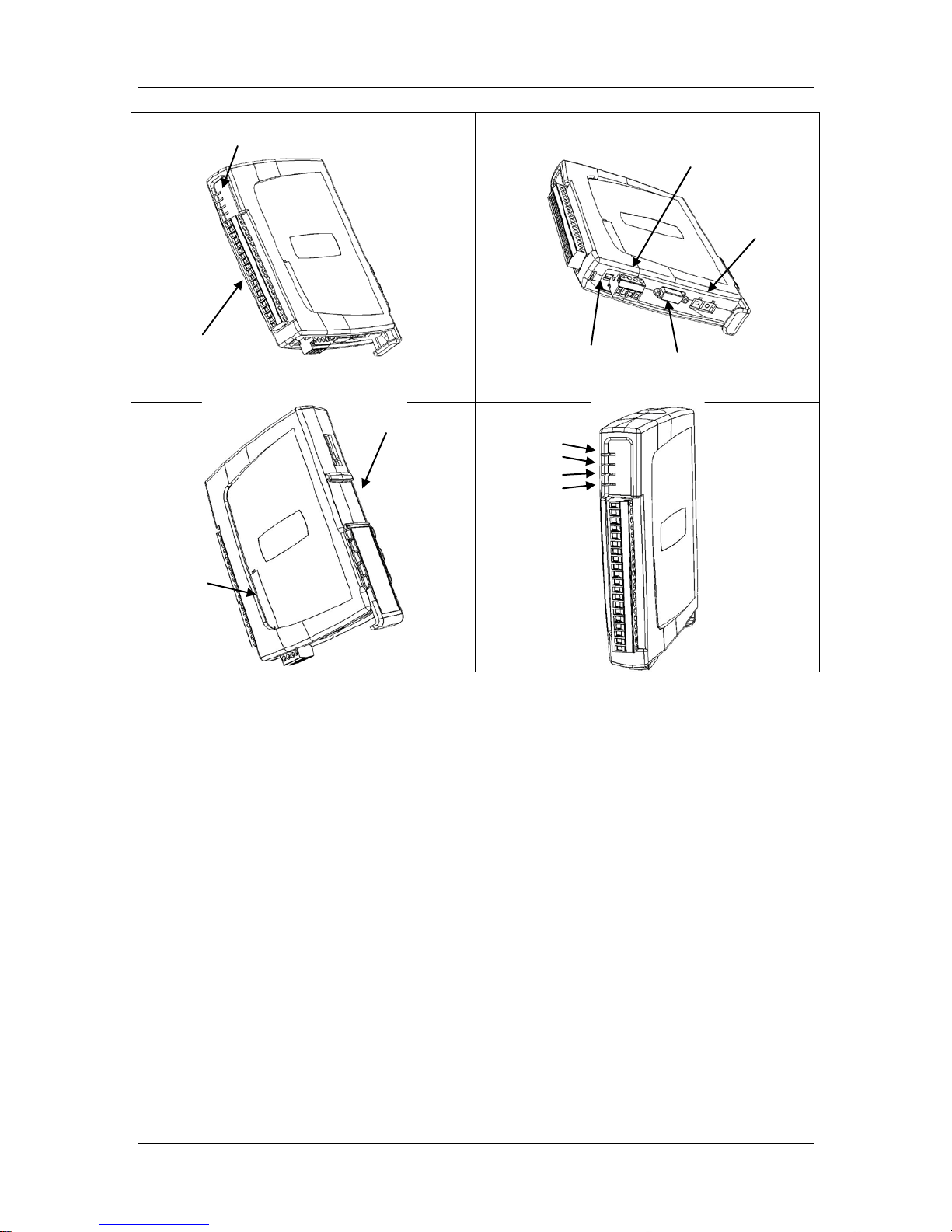
Figure 1-1 shows a diagram of a 115S module with parts labelled.
man_115S_1.14.docx Page 5
Page 6
115S Serial I/O Module User Manual
I/O connector
RS485 and
RS232 configuration
Address switches
DIN rail mount
Analog
access panel
Power
RS485
Status LEDs
configuration
power connector
termination
switch
OK
Transmit
Receive
connector
Figure 1-1: 115S unit with significant parts labeled.
Two ports allow configuration and communications on the 115S. The RS232 port is
intended for configuration. The RS485 port allows the unit to be in a multi-drop
configuration.
Overvoltage protection and supply monitoring is provided to minimize the risk of failure
due to faulty connections or supply surges.
Page 6 June 2011
Page 7
115S Serial I/O Module User Manual
1.1 Module types and features
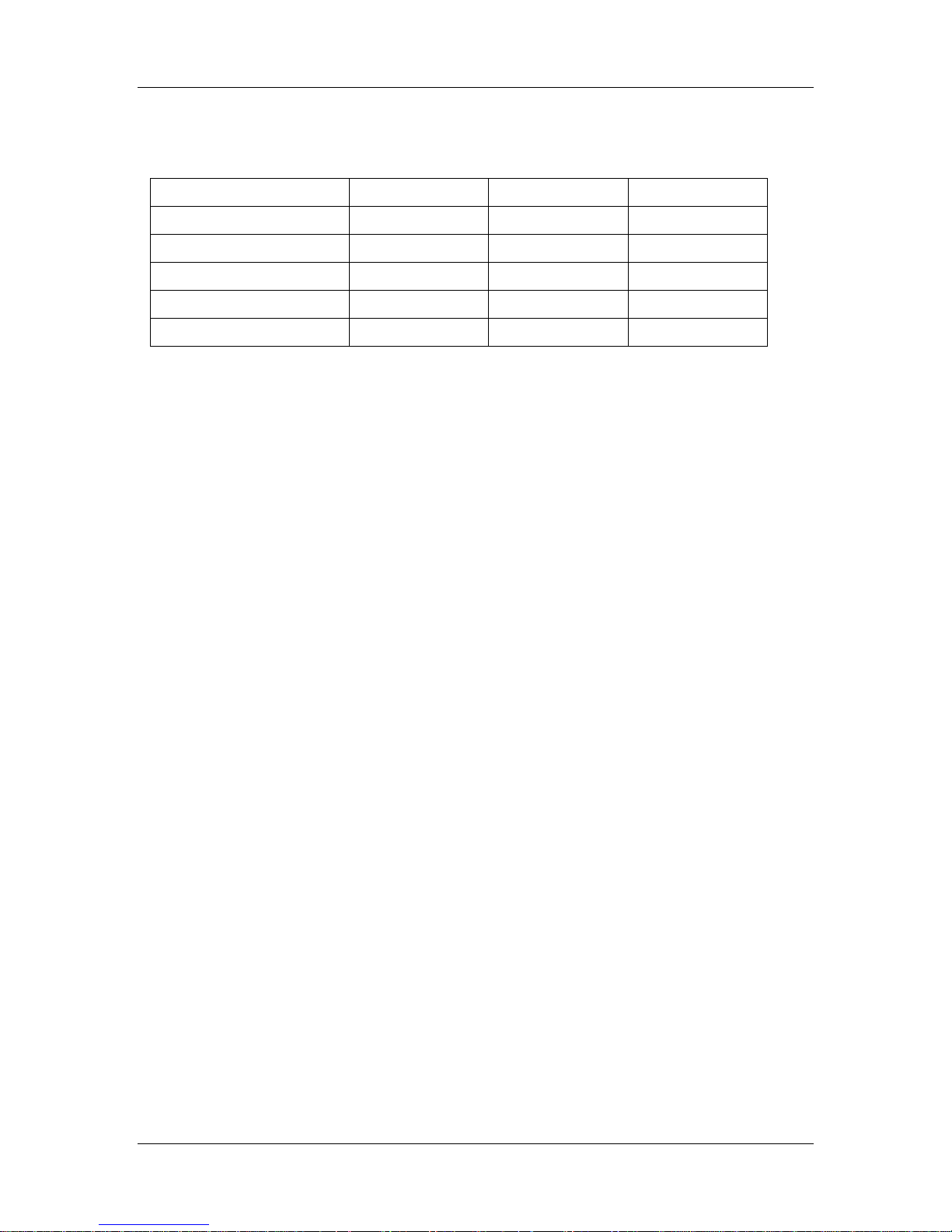
The module types and I/O are summarised in Table 1-1.
115S -11 -12 -13
Digital inputs/outputs
Pulse outputs
Pulse inputs
Analog inputs
Analog outputs
16 8 8
8 8 8
4 - -
- 8 -
- - 8
Table 1-1: Summary of 115S module types and I/O.
1.1.1 Digital inputs / outputs
Each digital I/O channel on the 115S modules can act as either an input or an output. The
input/output direction does not need to be user configured.
Digital inputs are suitable for voltage-free contacts, or NPN-transistor switch devices.
Digital outputs are open-collector transistor outputs, able to switch loads up to 30VDC,
200mA.
If you have wired an input/output channel as an input, it is recommended that you do not
write values to it as an output. No electrical damage will occur if you attempt to use a
channel wired as an input as an output, or vice-versa, however the I/O system will not
operate correctl y.
We recommend that the required digital inputs be assigned consecutively from channel 1.
Then use the remaining channels as digital outputs.
1.1.2 Pulsed outputs
The first eight digital channels on each 115S module can be used as pulse outputs. The
maximum output frequency is 50Hz.
A pulse output on the 115S will output the number of pulses equal to the register value
sent by the master. When the master sends a new register value, the 115S will output
additional pulses until the output count is the same as the new value.
Three register values are associated with creating each pulsed output:
• The Count keeps a tally of how many pulses have been output - this is a 16-bit
register and overflows to 0.
• The Target is set by the master, and is the trigger for pulses to be created. The
digital channel outputs pulses until the Count value reaches the Target value. If
the Target register is set to 0, the pulses stop and the Count register is cleared.
man_115S_1.14.docx Page 7
Page 8

115S Serial I/O Module User Manual
• The Update Time is the interval in which the 115S expects to receive updates to
the Target value. The module will output enough pulses for the Count to reach the
Target within the update time. The output pulse rate is determined by the update
time, and the difference between the count and the target.
If the calculated pulse rate is more than the maximum rate (50Hz), the 115S will output
pulses at the maximum rate. At the end of the update time, the count value will be less
than the target. The 115S will then calculate the new required pulse rate for the next
update period, based on the difference between Count and Target values.
If the calculated pulse rate is greater than around three times the maximum rate, pulses
are not output. The Count value will be set to the value of the Target without any pulses
output. Pulses will be output again when the calculated pulse rate falls within the
maximum possible rate.
1.1.3 Pulsed inputs
The first four digital channels on the 115S-11 module can be used as pulsed inputs. The
maximum input pulse frequency is 1 KHz.
The pulse input channel calculates two register variables, each of which can be read by
the Modbus master.
• The Pulse Count is a count of the pulses detected on the channel since the 115S
powered up. The pulse input counts are 32-bit values (2 x 16-bit registers, a low and
a high register), and wrap around to zero on overflow.
• The Pulse Rate is a measure of the rate of pulses detected on the channel. The pulse
rate value is decimal 16,384 (hex 4000) for zero rate and decimal 49,152 (hex C000)
for the maximum rate configured by the user. These zero and maximum values are
the same as 0% and 100% used for analog values. (See section 5.4 for hex to decimal
conversion.)
The maximum pulse input rate is set during configuration. The value is in pulses per
minute and is limited to 60000 (1 KHz), the maximum rate capable of the module.
1.1.4 Analog inputs
The analog inputs on the 115S-12 can be connected as either grounded single-ended
inputs or as floating differential inputs. The 115S-12 has eight grounded inputs or four
floating inputs.
• Grounded single-ended inputs connect between the AIN terminal and the GND
terminal.
• Floating differential inputs each take up two terminals. There are four diff e r ent ial
pairs on the 115S-12: [AIN1-AIN2], [AIN3-AIN4], [AIN5-AIN6], [AIN7-AIN8]. For
Page 8 June 2011
Page 9

115S Serial I/O Module User Manual
example, the first input is connected to terminals AIN1 (positive) and AIN2
(negative).
The two types of input cannot be mixed - all inputs must be either “grounded” or
“floating”.
Inputs can also be selected as mA current, or voltage input - all inputs must be the same,
either all current or all voltage. The scale of each analog input is chosen during hardware
configuration, with scale options as follows:
Voltage input scale options: [0 to 5V], [0 to 10V], [1 to 5V]
Current input scale options: [0 to 10mA], [0 to 20mA], [4 to 20mA]
For compatibility with E-Series modules, 4-20mA current is recommended. See section
4.4 for more information on compatibility.
The values on the analog input are decimal 16,384 (hex 4000) for minimum signal (0%)
and decimal 49,152 (hex C000) for maximum (100%).
The analog channel will measure over-scale, up to 150% which will have value 65,536
(hex FFFF). For 4-20mA signals, the channel will measure under-scale down to 0mA
which has a value of 8,192 (hex 2000). (See section 5.4 for hex to decimal conversion.)
The 115S-12 provides a 24V analog loop supply (“ALS”) for powering analog loops.
1.1.5 Analog outputs
The 115S-13 has eight analog output channels and can be configured to output voltage or
current. For current signals, “source” or “sink” can be selected. The scale of each analog
output is specified during configuration, with scale options as follows:
Voltage output scale options: [0 to 5V], [0 to 10V], [1 to 5V]
Current output scale options: [0 to 10mA], [0 to 20mA], [4 to 20mA], source or sink
• Voltage outputs are measured with respect to the ground terminal.
• Current source outputs are measured with respect to the ground terminal.
• Current sink outputs are measured with respect to the 24V “ALS” terminal.
Writing to the output register by the master produces the analog output. Minimum to
maximum signals (0 – 100%) are produced by register values from decimal 16,384 to
49,152 (hex 4000 - C000). (See section 5.4 for hex to decimal conversion.)
The analog channel can output over-scale, up to 150% corresponding to register value
65,536 (hex FFFF). For 4-20mA signals, the channel can output under-scale down to
0mA from a register value of 8,192 (hex 2000) or less. Note that the over-scale output is
limited by the maximum levels capable of the 115S module (12V or 24mA).
man_115S_1.14.docx Page 9
Page 10

115S Serial I/O Module User Manual
1.1.6 Communications
The 115S modules have two communication ports: RS232 and RS485. The RS485 port
communicates using E-Series protocol. Both ports support Modbus protocol.
The RS232 port is intended for configuration. The RS485 port is intended for normal
operation and can be used in a multi-drop setup.
There are two address switches on the base of the module. When the switches are set
within the range 01-99, the module uses Modbus protocol on the RS485 port, with the
Modbus address defined by the switches. Setting both address switches to 00 configures
the module to use E-Series protocol on the RS485 port. Whenever these address switches
are changed the unit should be reset by disconnecting power.
Note - When configured for E-Series protocol the maximum number of expansion
modules per radio is 10 as each module requires 3 addresses.
When using E-Series protocol, the port settings are fixed at 9600 baud, 8 data bits, no
parity, 1 stop bit.
The Modbus communications settings are configurable as follows:
Modbus type: RTU, ASCII with 8 data bits, ASCII with 7 data bits. (Note that the
configuration software only supports Modbus RTU. A Modbus Master can select ASCII
protocol by writing to the appropriate register. See Appendix A.)
Baud rate: 1200, 2400, 4800, 9600, 14400, 19200, 28800, 38400, 57600, 76800, 115200
Parity: none, odd, even
Stop bits: 1 or 2.
The modules are fitted with a termination switch for the RS485. Set this switch only on
the last module in a multi-drop RS485 configuration.
The ELPRO E-Series software is used to configure the 115S modules as part of an
E_Series network. The hardware set-up for items such as expected pulse rates and analog
signals is also available through this software.
When used as a Modbus-only device, stand-alone configuration software
(cfg_115S_Vx.xx.exe) is available to set up the modules. All required software may be
downloaded from the ELPRO website.
Page 10 June 2011
Page 11
115S Serial I/O Module User Manual
B A - +
2 Installation
All connections to the module should be SELV only. Normal 110/220/240V mains
supply should not be connected to any input terminal of the module.
2.1 General installation
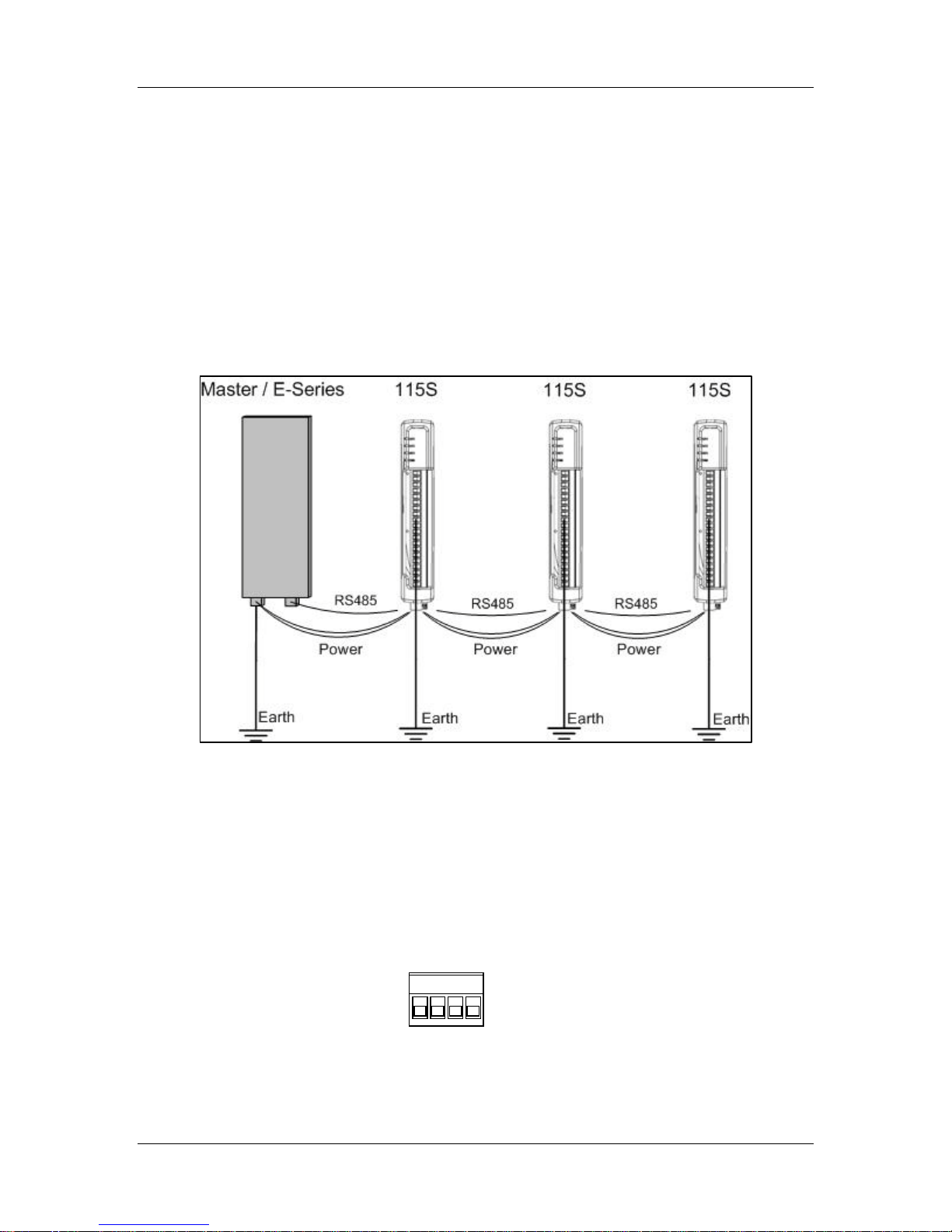
Several 115S modules may be connected to one Master / E-Series Radio via RS485
multi-drop connection as shown in Figure 2-1. Ensure there are good connections
between the 115S units and the master and a separate Earth connected to the ‘GND’
terminal on the front Terminal block of each module. 2.5 sqmm / 12 gauge earth wire is
recommended.
Figure 2-1: Several 115S units connected to a master.
2.1.1 Power Connection
The 115S modules require a 10.8-30 VDC ** power supply. This is supplied to the 4-way
connector, shown in Figure 2-2.
** Model Dependent. Check rear label for actual operating voltages
Figure 2-2: Power and RS485 connector.
Connect 10.8-30 VDC to + and earth to -. Connect RS485 to B and A.
man_115S_1.14.docx Page 11
Page 12
115S Serial I/O Module User Manual
ON
RS485
Up = terminate
Down = unterminated
Master
115S
115S
115S
A B A B A B A
B
Termination
2.1.2 Address Switches
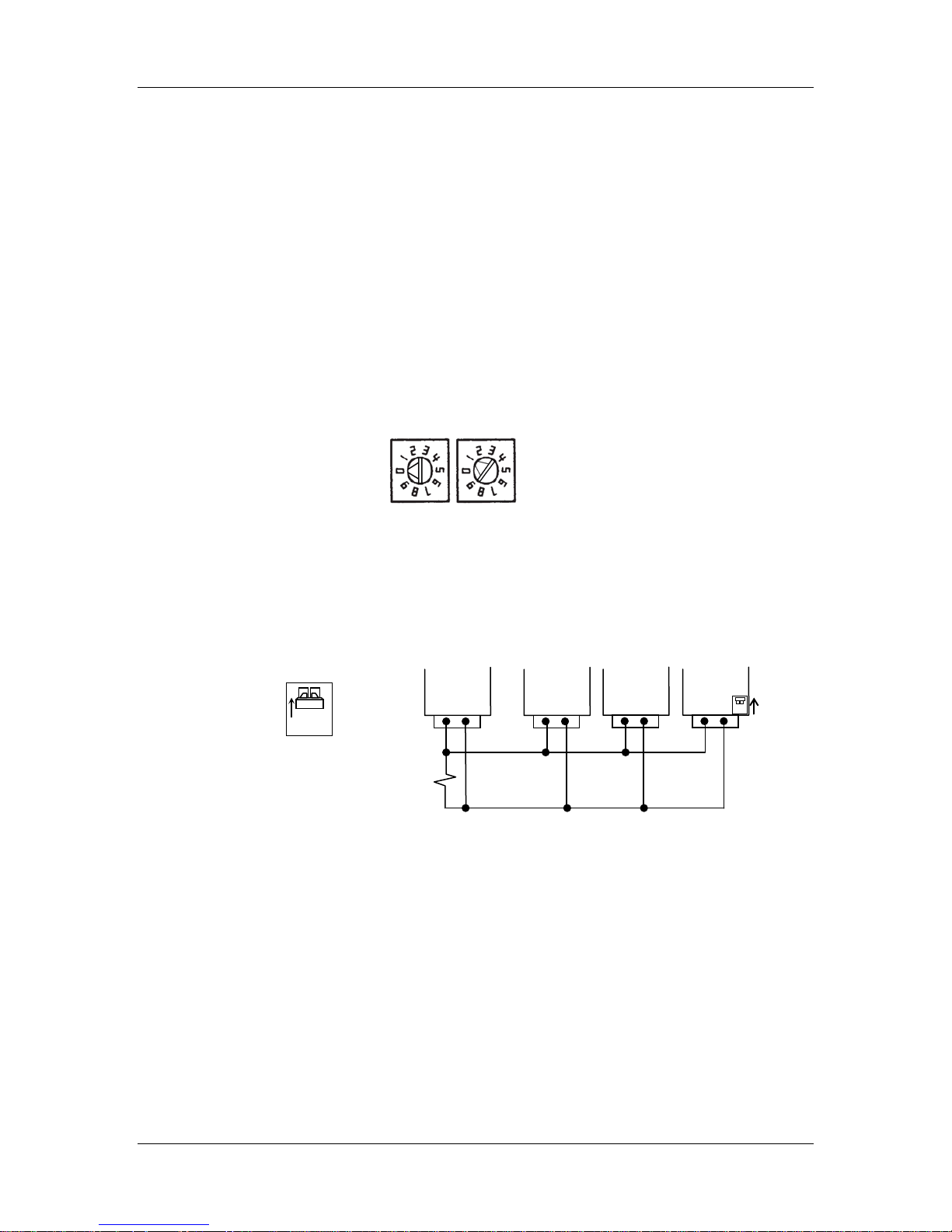
The address switches are found on the bottom panel of the module, as shown in Figure
2-3. If you are using the 115S module with other ELPRO E-Series modules (ELPRO 105
and 905- modules), the address switches must be set to “00”. This enables ELPRO
protocol mode and assigns 3 serial addresses to each module.
If you are using a Modbus Master device, ensure each 115S connected to the same
Modbus master has a unique Modbus address.
Note that the module must be reset after changing the address switches.
You can connect to an ELPRO 105U-G-MD1 or 905U-G-MD1 Module using either
MODBUS protocol or ELPRO protocol. ELPRO protocol is easier to set up, and we
recommend using this protocol for most applications.
x10 x1
Figure 2-3: Address switches. The address shown is 01.
Connect the RS485 B and A wires to the 4-way connector shown previously in Figure
2-2. An RS485 termination switch is provided. Terminate the last 115S module in the
multi-drop setup as shown in Figure 2-4.
switch up
(terminated)
termination
switch.
120Ω
Figure 2-4: RS485 multi-drop connection and termination (only use external
termination for the master if it does not have internal termination).
Page 12 June 2011
Page 13
115S Serial I/O Module User Manual
Transistor
V+
V+
V-
DIO1
DIO2
EARTH
2.2 Signal Connections
All connections to the module should be SELV only. Normal 110/220/240V mains
supply should not be connected to any input terminal of the module.
2.2.1 Digital Inputs (and Pulsed Inputs)
The 115S-11 supports 16 digital signals, and the 115S-12 and 115S-13 support 8 digital
signals. Additionally, digital inputs DIO1-4 on the 115S-11 operate as pulse inputs.
Digital output signals share the same terminals as the Digital input signals, marked DIO18, and DIO1-16 on the 115S-11 module.
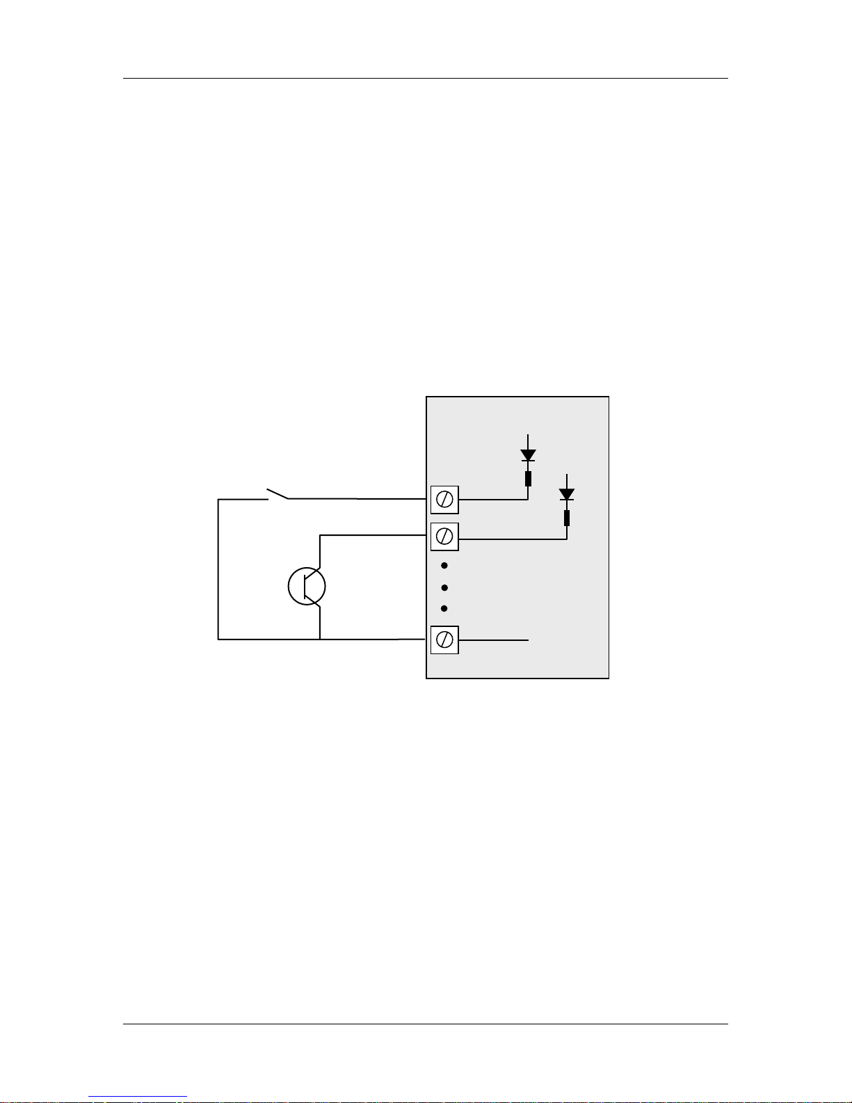
A digital input is activated by connecting to EARTH, either by voltage-free contact or by
a transistor switch. Refer to Figure 2-5:
115S Module
Voltage-free contact
switch device
Figure 2-5: Connection of digital inputs.
man_115S_1.14.docx Page 13
Page 14
115S Serial I/O Module User Manual
_
+
DC
Max 30VDC
V-
DIO1
DIO2
EARTH
115S Module
2.2.2 Digital Outputs (and Pulsed Outputs)
The 115S-11 supports up to 16 digital outputs, shared with the digital input function on
the same terminals. The 115S-12 and 115S-13 both provide 8 digital output signals.
These signals are marked DIO1-8, and DIO1-16 for the 115S-11. On all 115S modules,
DIO1-8 can also operate as pulsed outputs.
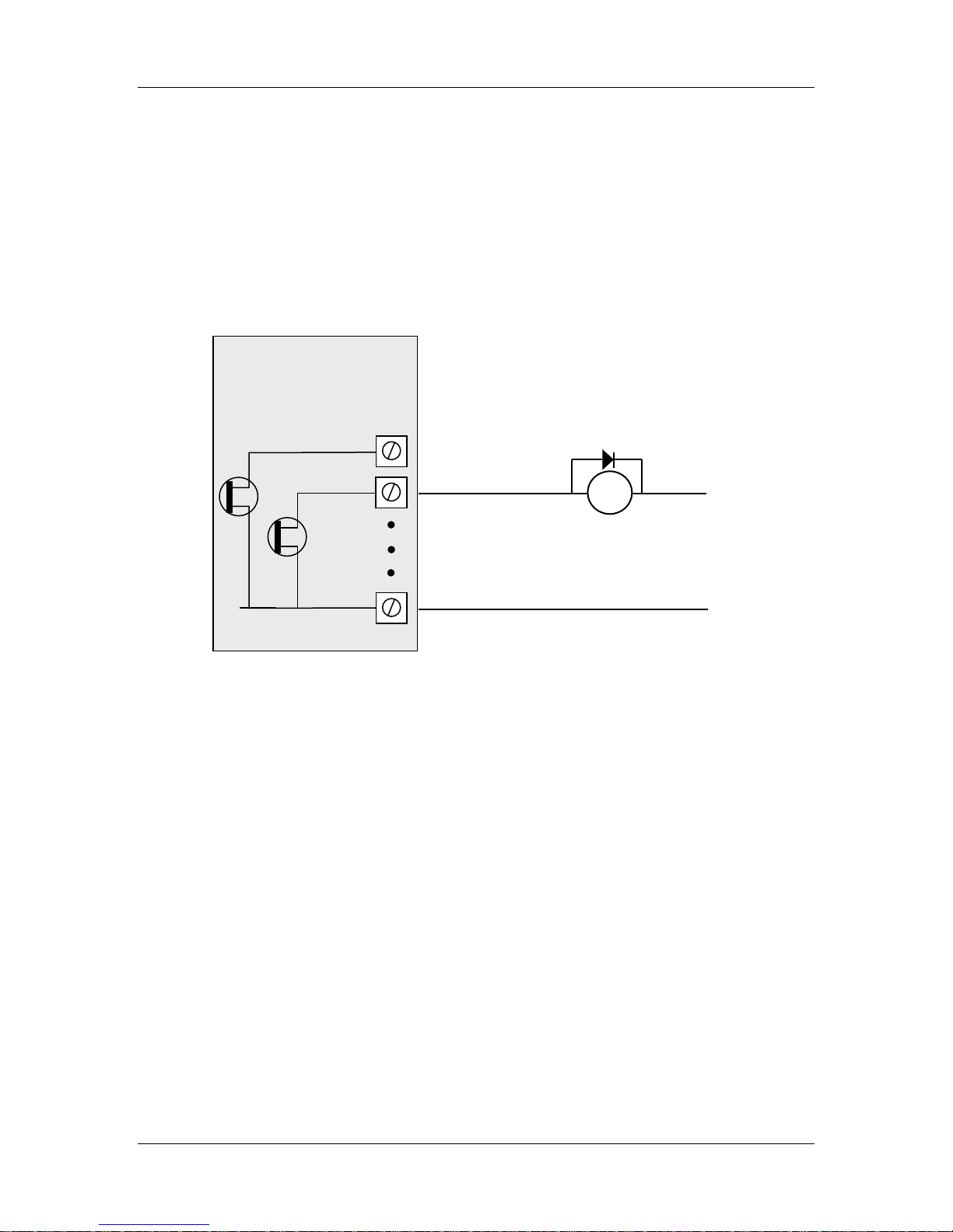
When active, digital outputs provide a transistor switch to EARTH. To connect a digital
output, refer to the diagram in Figure 2-6. A bypass diode is recommended to protect
against switching surges for inductive loads such as relay coils.
Load
0.2A
Figure 2-6: Connection of digital outputs.
Note that digital outputs will only switch DC circuits, with maximum voltage 30VDC.
2.2.3 Analog Inputs
The 115S-12 provides eight grounded single-ended or four floating differential analog
inputs. These provide measurement of voltage signals (0-10V) or current (0-20 mA)
signals. An internal 24V analog loop supply (ALS) is generated for current loops.
Refer to Section 4.4 for detail on configuring single-ended, differential, current-mode or
voltage mode inputs.
2.2.3.1 Grounded Single-Ended mA Inputs
Single-ended current inputs allow twice as many inputs as the differential mode. This
mode is useful when the sensor loop can be grounded to the 115S module. Devices may
also be powered by the 24V supplied by the 115S. Refer to Figure 2-7:
Page 14 June 2011
Page 15
115S Serial I/O Module User Manual
AIN1
AIN2
AGND
115S-12 Module
ALS +24V
Loop powered
Externally powered
+
- + -
sensor
sensor
V-
Figure 2-7: Connection for single-ended current inputs. Transducers may be
externally powered or powered by the 115S +24V loop supply.
Note:
- The module is configured at the factory for this type of input
- To change the input configuration, refer to section 4.4
WARNING !
Ensure correct DIP switch positions AND software configuration has been
completed for each analogue input BEFORE connecting external signals to the
115S-12 module.
man_115S_1.14.docx Page 15
Page 16
115S Serial I/O Module User Manual
V-
AIN3
AIN4
AGND
ALS +24V
Externally powered
+
-
AIN1
AIN2
+
-
Power
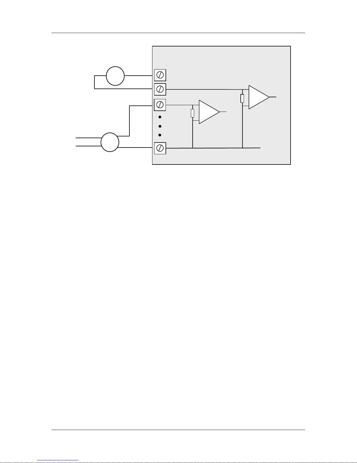
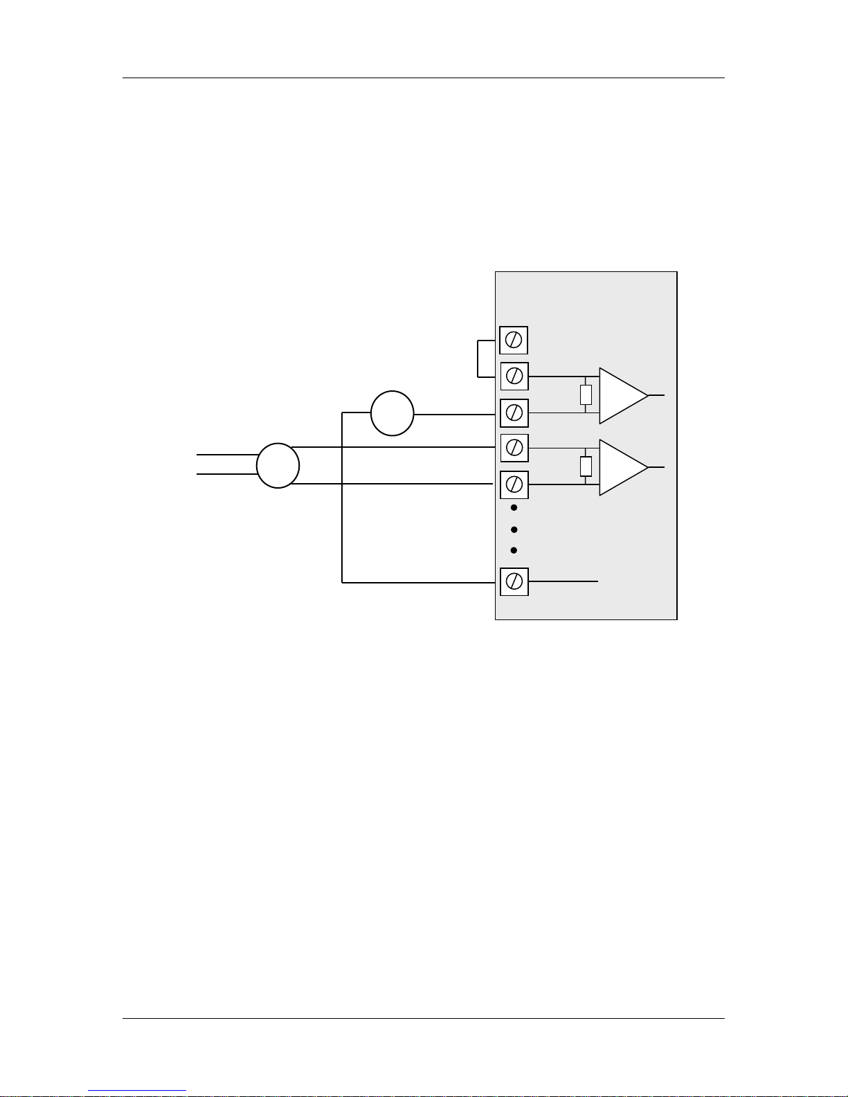
2.2.3.2 Floating Differential Mode mA Inputs
Differential mode current inputs should be used when measuring a current loop which
cannot be connected to earth or ground. This allows the input to be connected anywhere
in the current loop. Common mode voltage can be up to 27VDC.
Up to four loops can be connected, to terminal pairs [AIN1-AIN2], [AIN3-AIN4],
[AIN5-AIN6], [AIN7-AIN8] - the former terminal is +ve and the latter –ve.
The diagram in Figure 2-8 indicates how to connect devices for differential mode current
inputs.
115S-12 Module
Loop powered
sensor
supply
sensor
Figure 2-8: Connections for differential current inputs.
Note:
- The module configuration needs to be changed for this type of input
- To change the input configuration, refer to section 4.4
WARNING !
Ensure correct DIP switch positions AND software configuration has been
completed for each analogue input BEFORE connecting external signals to the
115S-12 module.
Page 16 June 2011
Page 17
115S Serial I/O Module User Manual
AIN3
AIN4
AGND
115S-12 Module
ALS +24V
Sensors with
AIN1
AIN2
+ - +
-
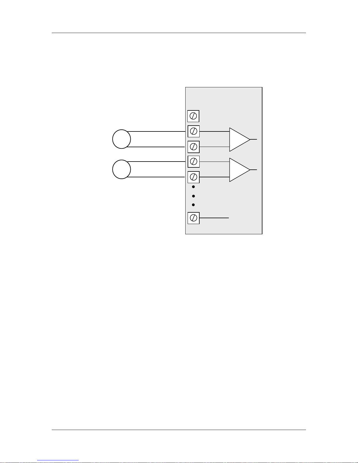
2.2.3.3 Floating Differential Voltage Inputs
Differential voltage inputs allow a voltage to be measured when it cannot be referenced
to earth or ground. The diagram in Figure 2-9 shows how to connect differential voltage
inputs. The module has a 27V common mode input range.
voltage signals
V-
Figure 2-9: Connection for differential voltage input mode.
Note:
- The module configuration needs to be changed for this type of input
- To change the input configuration, refer to section 4.4
WARNING !
Ensure correct DIP switch positions AND software configuration has been
completed for each analogue input BEFORE connecting external signals to the
115S-12 module.
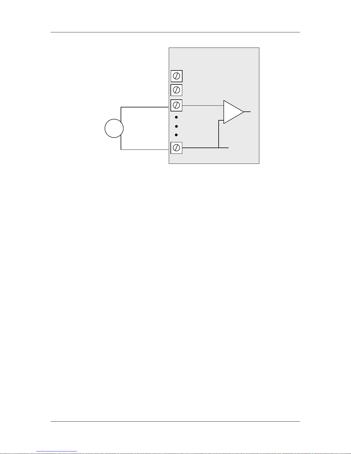
2.2.3.4 Single-ended Voltage Input
Single-ended voltage inputs allow twice as many inputs as differential mode. This mode
is useful when one end of the input voltage can be connected to the ground of the 115S
module. Figure 2-10 shows connections for single-ended voltage input.
man_115S_1.14.docx Page 17
Page 18
115S Serial I/O Module User Manual
V-
AIN1
AIN2
AGND
115S-12 Module
ALS +24V
Sensor with voltage
signal
Figure 2-10: Connection for single-ended voltage input.
Note:
- The module configuration needs to be changed for this type of input
- To change the input configuration, refer to section 4.4
WARNING !
Ensure correct DIP switch positions AND software configuration has been
completed for each analogue input BEFORE connecting external signals to the
115S-12 module.
2.2.4 Analog Outputs
The 115S-13 provides eight analog outputs. These may be configured as voltage or
current outputs. The current output may be selected as “sink” or “source” current.
Refer to Section 4.5 for detail on configuring analog outputs.
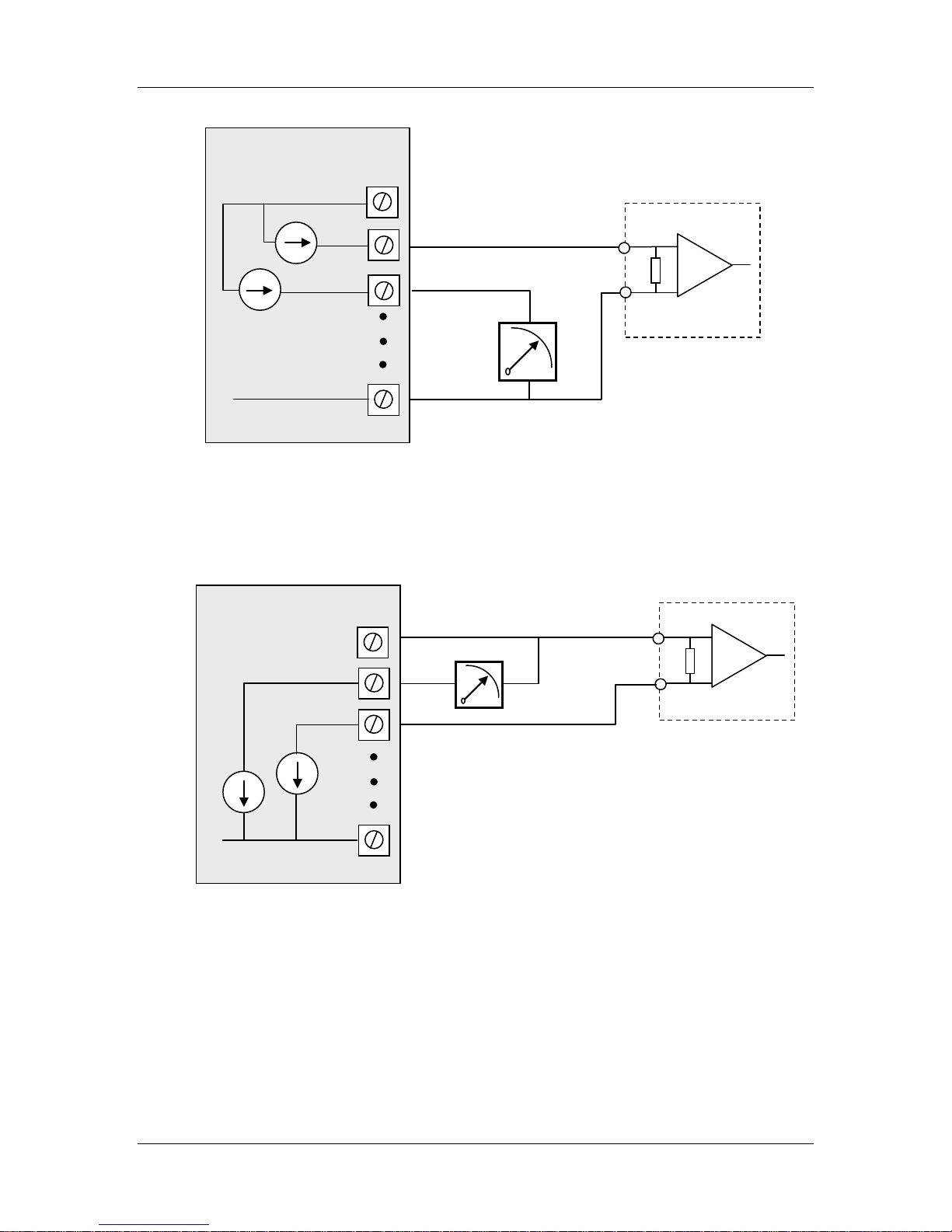
2.2.4.1 Current Output
Current output mode may be configured for current source or current sink. Figure 2-11
shows the connections for current source mode. Figure 2-12 shows the connections for
current sink.
Page 18 June 2011
Page 19
115S Serial I/O Module User Manual
AOT1
AOT2
AGND
ALS +24V
PLC
AI+
AI-
V-
AOT1
AOT2
AGND
115S-13 Module
ALS +24V
PLC
AI
COM
+
-
+
-
Figure 2-11: Connection for current source output.
Note:
- The module is configured at the factory for this type of output connection
- To change the input configuration, refer to section 4.5
115S-13 Module
V-
Figure 2-12: Connection for current sink output.
Note:
- The hardware configuration needs to be changed for this type of output
connection
- To change the hardware configuration, refer to section 4.5
man_115S_1.14.docx Page 19
Page 20
115S Serial I/O Module User Manual
V-
AOT1
AOT2
AGND
ALS +24V
PLC
AI
COM
+
-
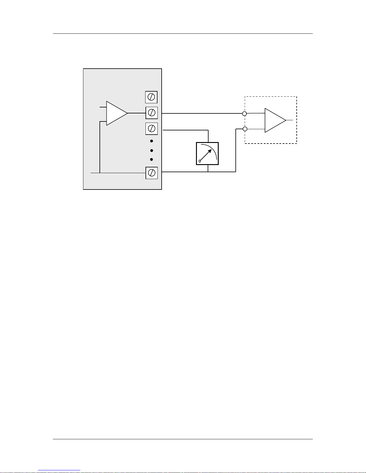
2.2.4.2 Voltage Output
Voltage output mode produces a voltage referenced to the module’s AGND. Figure 2-13
shows the connection for voltage output configuration.
115S-13 Module
VOLTAGE
INPUT
Figure 2-13: Connection for voltage output configuration.
Page 20 June 2011
Page 21

115S Serial I/O Module User Manual
3 Configuration
The 115S serial expansion modules can be configured as expansion I/O for the ELPRO
radio modules. When configured like this the module communicates using standard
ELPRO protocol which works on a Change of State concept like all other ELPRO radio
modules.
The module can also be configured as a Standard MODBUS Slave device which operates
by responding to poll messages from a MODBUS Master (DCS, SCADA, PLC, Etc).
3.1 ELPRO Expansion I/O configuration.
Use the ELPRO Configuration utility to configure the 115S module to communicate to
105U and 905U radio modules.
- Ensure the Address switches are set to “00” for ELPRO protocol mode. Refer to
section 2.1.2 for details on setting the address switches.
The ELPRO Configuration utility allows you to configure systems consisting of a
mixture of ELPRO Module types.
The software can be downloaded from the ELPRO web-site, or from the ELPRO Product
CD included with your device.
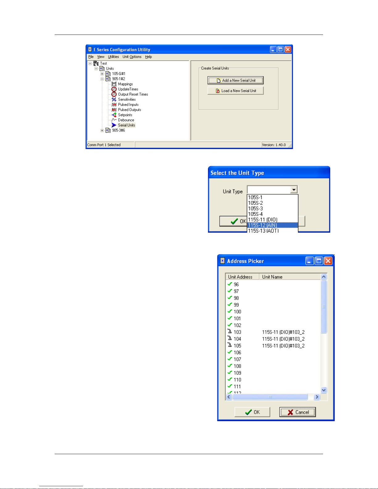
115S expansion I/O module can only be added to the software via the ‘Serial Units’
branch of a radio module, see Figure 3.1 below.
If using the module as a standalone serial device (without radios) you will need to add a
dummy radio module to the software and then add all serial module to this dummy
modules ‘Serial Units’ branch.
- Refer to your radio module user manual for an explanation on how to create the
radio module configuration.
Once you have created the new radio module configuration, or a radio module was
already present you can add a serial module. Select the radio module that you want to
connect the 115S serial module to, and select the “Serial Units” item. Select “Add a new
Serial Unit” to create the new configuration, or select “Load a New Serial Unit” to load
the configuration from an existing module. See Figure 3-1 & 3.2 below.
man_115S_1.14.docx Page 21
Page 22
115S Serial I/O Module User Manual
Figure 3-1: Configuration of 115S modules using ELPRO Configuration Utility.
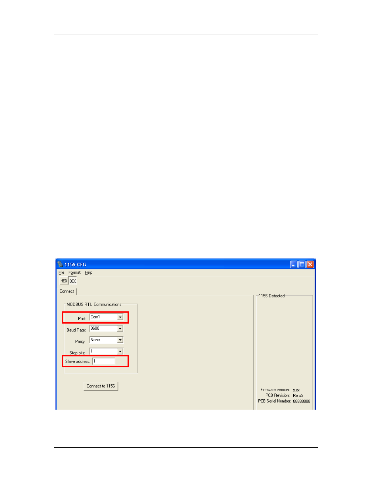
When you select “Add a new Serial Unit” you
will need to select the unit type. Select the
correct module type here.
Figure 3-2: Select the unit type.
Finally, you will be prompted to select the module
address. You can choose to allow the configuration
software to select an unused address for you, or you
can select the module address manually.
- Serial Module address must be in the range
96 to 127.
- Every serial module that is connected to the
same radio module needs a separate address.
- You can use the same address on two
different serial modules if they are
connected to different radio modules.
Note – When using modules as Elpro Expansion
I/O each module will be assigned 3 addresses.
Once you have added the new module you can
configure I/O mappings the same way you would
for the older 105 series modules or a radio module.
For more information on configuring ELPRO ESeries modules using the E-Config software, refer
to the 105-1 or 905-1 user manual.
Figure 3-3: Select unit address.
Page 22 June 2011
Page 23

115S Serial I/O Module User Manual
3.2 MODBUS Slave Configuration
If configured as a MODBUS Slave the module will need to have a unique Slave address,
see section 2.1.2 “Address Switches” above for details on how this is done.
The Address selected will be the address that the MODBUS Master needs to poll to
gather data.
The module also has a number of internal registers that hold the I/O values, status, etc.
These register are polled by the MODBUS Master using standard commands that
Read/Write values to or from the device.
When the Modbus Master Polls the Slave is does so using a Modbus Command and an
I/O location. This Modbus command will varies depending on whether they are Inputs /
Outputs and Analog / Digital values
Example
• To read a Digital Input on the module an “02: Input Status” command is
used and the Modbus address will be in the range 10001 – 19999
• To read an Analog input on the module an “04: Input Register” Command
is used and the Modbus address will be in the range 30001 – 39999.
• To write to a Digital output (Turn it on) you need to use a “01: Coil
Status” Command and the Modbus address location will be 0001 – 9999
• To Write to an Analog output you will need to use an “03: Holding
Register” command and the Modbus Address will be in the range 40001 –
49999
See Appendix A “Modbus address map” for the I/O registers locations.
Note: all Analog values are 16 bit unsigned integers.
We recommend using Wintech’s Modscan and Modsim which are low cost Modbus
Master and Modbus Slave simulators to help diagnose any Read/Write addressing issues.
www.win-tech.com
man_115S_1.14.docx Page 23
Page 24
115S Serial I/O Module User Manual
4 Hardware Configurat ion
Hardware Set-up allows the 115S hardware function to be adjusted to suit the application.
To configure the hardware settings, you need:
- Access to the DIP switches under the Analog Configuration Panel (refer Figure
1-1: 115S unit with significant parts labeled.)
- Configuration Software to run on your PC.
Configuration of the 115S modules is performed by either the dedicated 115S
configuration software (cfg_115S_Vx.xx.exe), or by the ELPRO E-Series configuration
software (from the Utilities / Advanced - SXM menu). The software is available from
ELPRO’s Product CD or web page
4.1 Connecting to the 115S module
To use the configuration software, perform the following steps:
• Connect the 115S to the PC COM port with a standard serial cable (straight-through,
DB9 female to DB9 male. See Appendix for wiring.)
• Set the address switches to 00
• Supply power to the 115S via the “+” and “-” terminals on the bottom of the module
(10.8-30 VDC **).
** Model Dependent. Check rear label for actual operating voltages
• Start the configuration software on your PC or laptop (cfg_115S_Vx.xx.exe)
Figure 4-1: Main configuration screen.
Page 24 June 2011
Page 25
115S Serial I/O Module User Manual
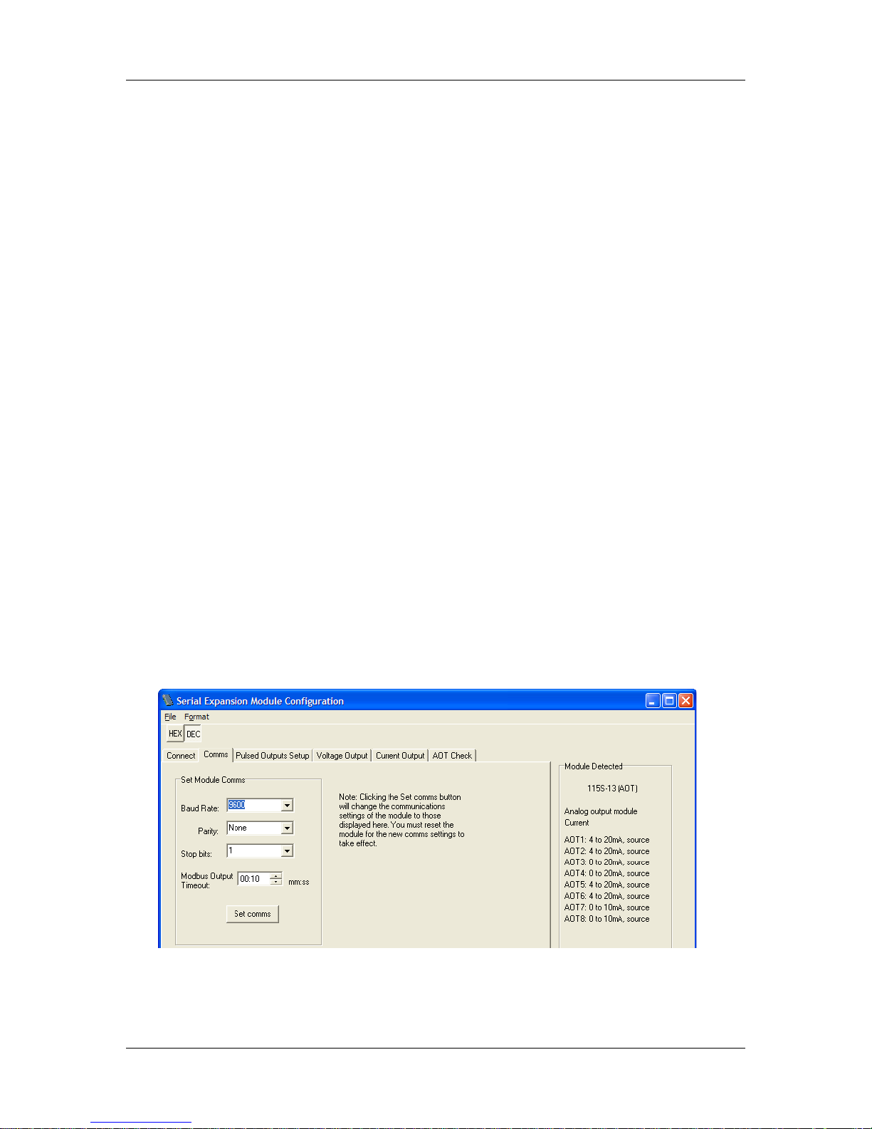
• Set the “Port” setting to match the computer com port you have connected to.
• Set the “Slave Address” to match the address switch setting of the 115S. If you are
using address “00” for ELPRO Protocol, set the Slave Address to 100.
• Set the communications parameters. The default communications parameters are:
Baud rate: 9600
Parity: NONE
Stop bits: 1
Click the button labelled Connect to 115S.
If you are unable to communicate with the 115S, refer to Appendix C: Comms Recovery.
If connection has been successful, several folder tabs will become available, depending
on the module type. The panel on the right-hand side of the form shows the 115S detected
and its settings.
4.2 Configuration common to all modules
4.2.1 Communications
Select the Comms folder tab. This page allows you to change the communications
settings of the 115S.
These settings are applied to both the RS-232 configuration port and to the RS-485
Modbus interface port.
Choose the required settings, then click Set comms. You will need to power off / on the
115S for the new settings to take effect.
Figure 4-2: Communications configuration screen.
man_115S_1.14.docx Page 25
Page 26

115S Serial I/O Module User Manual
4.2.2 Modbus Output Timeout on Comms fail
The module when being used as a Modbus Slave device has an output reset on comms
fail feature.
This means the outputs are turned off after a configured timeout if the module doesn’t
receive any Modbus polls to itself.
Note: The Modbus Output Timeout feature is available in Firmware version 2.02
and above.
To set the Modbus Output reset time use the configuration software (V1.09 and above)
and under the “Comms” tab you will see a “Modbus Output Timeout”. Select the
appropriate time and then press the “Set Comms” button and then resetting the module.
See Figure 4-2 above
Note that you will need to change the connection settings on the “Connect” page, and reconnect to the 115S.
Maximum Output timeout is 34 minute 57 seconds.
Selecting 00:00 minutes and seconds will disable the outputs resetting.
Be aware the “Modbus Output Timeout” must be greater than the Modbus Master Poll
time or you will see the outputs reset before the next poll. Generally it is good practice to
configure the reset time to two or three times the Modbus poll time so as to ensure
accurate comms fail indication.
The “Modbus Output Timeout” can also be configured by the Modbus Master by writing
into register 204 in units of 32 msec.
E.g. A0 hex would be 5.12 seconds, 3A9 hex would be 30 seconds, and 249F
would be 5 minutes.
The module then needs to be reset for the settings to take effect.
Also the module must be operating in MODBUS mode, otherwise the reset outputs
feature is disabled, so the modules address must be set to something other than “00”.
If using the modules in ELPRO E-Series mode the Outputs also have a reset feature that
can be configured within the E-Series Configuration Utility.
Page 26 June 2011
Page 27
115S Serial I/O Module User Manual
Address
Description
40205
Configurable Ack timeout
Decimal Value
Timeout
Decimal Value
Timeout
1
32msec
1875
1 Min
16
500msec
3750
2 Min
31
1 Sec
7500
4 Min
62
2 Sec
9375
5 min
100
3.2 sec
18750
10 Min
156
5 Sec
28125
15 Min
312
10 Sec
37500
20 Min
469
15 Sec
46875
25 Min
625
20 Sec
56250
30 Min
1000
32 Sec
65535
34 Min 57 Sec
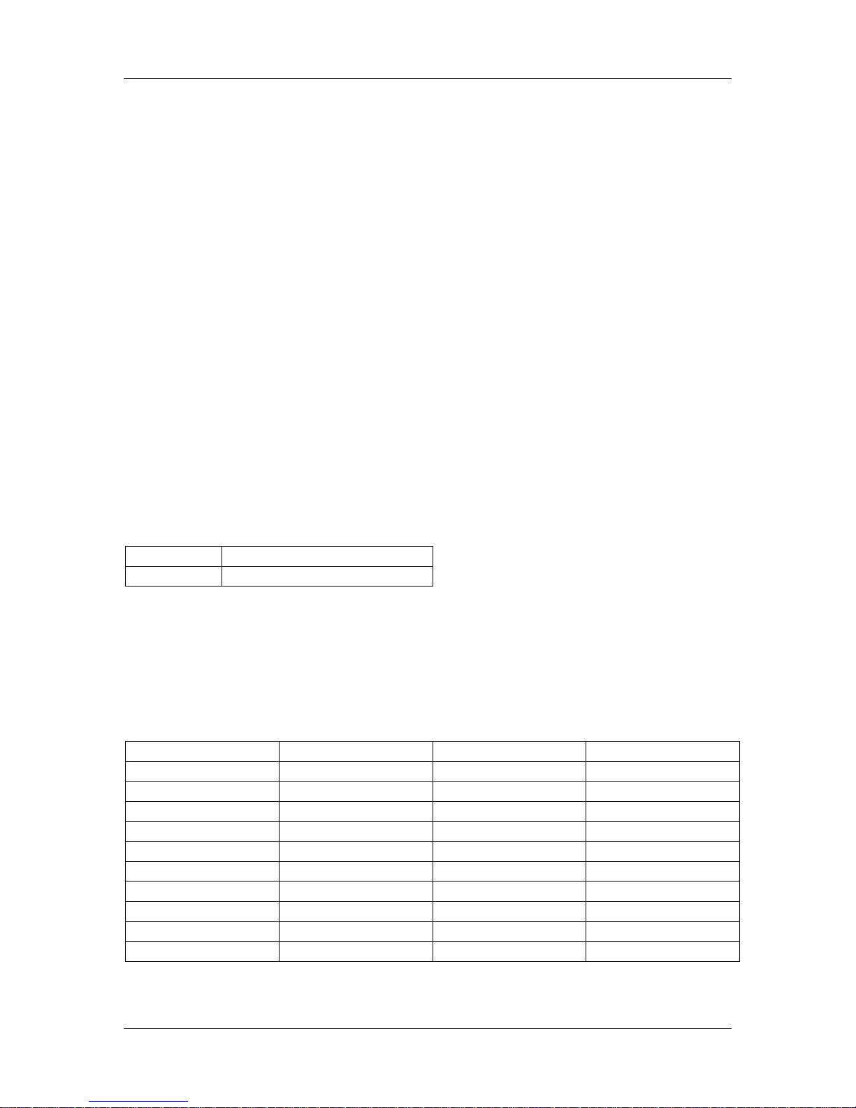
4.2.3 Configurable ACK Timeout
All communications between Elpro devices using Elpro Protocol is two way
communications. The initiating module sends a message to an end device and expects to
get a response within a given time period, this response is called an acknowledgement.
If this acknowledgment is not received in the allotted timeframe the message is retried up
to 4 times with a random 0-5 seconds delay between each retry. If all retries are not
acknowledged then a communications fail can be flagged.
Typically the 115S expansion I/O modules are used with 105U/905U I/O radios and the
longer Acknowledge Timeouts are not required.
If using the modules with Elpro modems or third party devices were the
acknowledgement is likely to take longer than 5 seconds then a configurable Ack time
can be implemented to overcome these timing issues. E.g. Communication path may have
a number of repeaters or be going through a network with longer timeframes (GSM or
Ethernet Networks)
Note: The Configurable Acknowledge timeout is only available in firmware version
2.04 and greater.
The configurable Ack timeout allows the wait time of this response to be extended by
adjusting a register shown in the table below.
The Ack timeout is configurable from 32msec to 34 minutes 57 seconds, see examples
below.
Ack Timeout will be added to the default random 0-5 sec retry time.
The factory value for the Ack timeout will be 0 which will use the default 0-5 second
staggered timeout.
man_115S_1.14.docx Page 27
Page 28
115S Serial I/O Module User Manual
4.2.4 Pulsed outputs
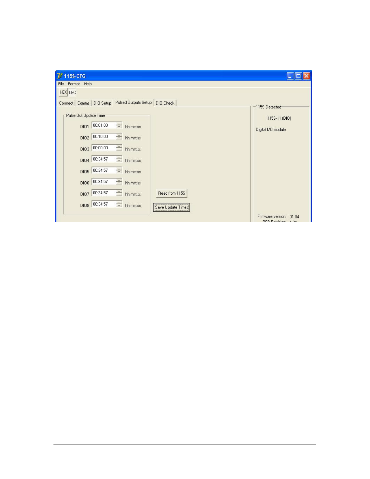
Choose the folder tab labeled Pulsed Outputs Setup, as shown in Figure 4-3.
Figure 4-3: Pulsed outputs setup page for a 115S-11. The pulsed outputs are
available on all models.
Clicking the button Read from 115S will read the pulse out update times from the 115S
and display them on the form.
The Pulse Out Update Times should be set to the approximate interval at which the 115S
will receive updates to its pulse out target register. The pulse output circuitry will attempt
to generate pulses at a rate that will reach the target pulse count within the update time.
For example, if the Modbus master unit is configured to send the register value for the
pulse output channel every 1 minute, then the Update Time should be set to 1 minute.
The maximum allowed pulse out update time is 34 minutes 57 seconds. Set the update
times for each channel in hours, minutes, and seconds. An update time of zero will never
produce any pulses.
After the update times have been set, click the Save Update Times button.
The pulse output feature can be tested on the Check folder tab (refer section 5).
Page 28 June 2011
Page 29
115S Serial I/O Module User Manual
4.3 115S-11 configuration
4.3.1 Pulsed Inputs
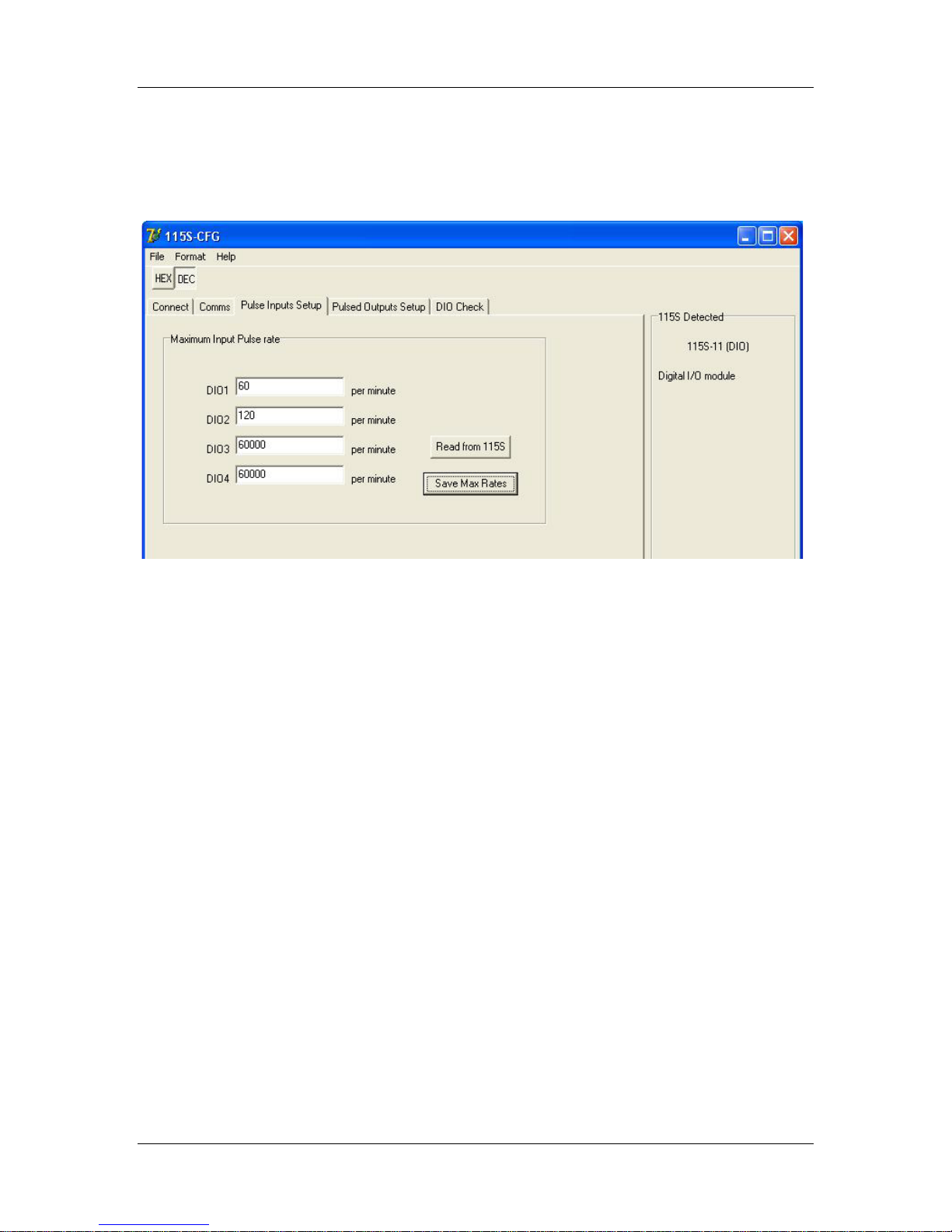
Choose the Pulse Inputs Setup page, as shown in Figure 4-4.
Figure 4-4: Pulse inputs setup. Only available on a 115S-11 module.
Clicking the Read from 115S button reads the existing maximum pulse rate settings from
the 115S and displays them on the form.
If pulse rate is to be used, the maximum pulse input rate must be set. The pulse rate value
is calculated as a fraction of the maximum pulse input rate. Specify the maximum pulse
input rate in pulses per minute. The highest allowable pulse input rate is 60000 pulses per
minute, or 1kHz.
Once the maximum pulse rates are specified, click the Save Max Rates button to save the
data to the 115S module.
The pulse input feature can be tested on the DIO Check page (refer section 5.1).
man_115S_1.14.docx Page 29
Page 30
115S Serial I/O Module User Manual
115S-12
115S-12
(V)
105-G
(hex)
105-1
(mA)
105-3
(mA)
0 to 5V
0
4000 4 4
5
C000
20
20
0 to 10V
0
4000 4 4
10
C000
20
20
1 to 5V
0
2000
0.5*
0
1
4000 4 4
5
C000
20
20
4.4 115S-12 configuration
4.4.1 Voltage input
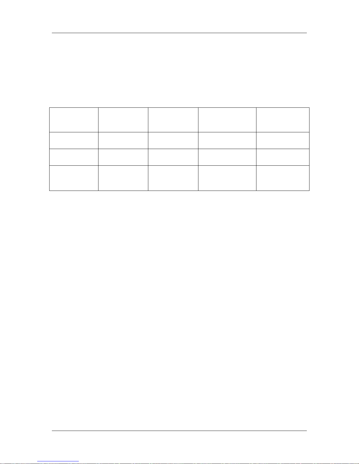
Voltage inputs may be selected in the scales 0 to 5V, 0 to 10V, or 1 to 5V. For each scale,
the minimum to maximum signal levels are represented by 4000 hex to C000 hex. Table
4-1 shows how the 115S-12 voltage readings translate to outputs in other ELPRO
products.
Voltage scale
Table 4-1: Compatibility of 115S-12 voltage inputs with other ELPRO products.
*
Reduced accuracy for less than 4mA in 105-1.
Input voltage
Register value
Output current
Output current
Page 30 June 2011
Page 31
115S Serial I/O Module User Manual
4.4.1.1 Single-ended voltage input
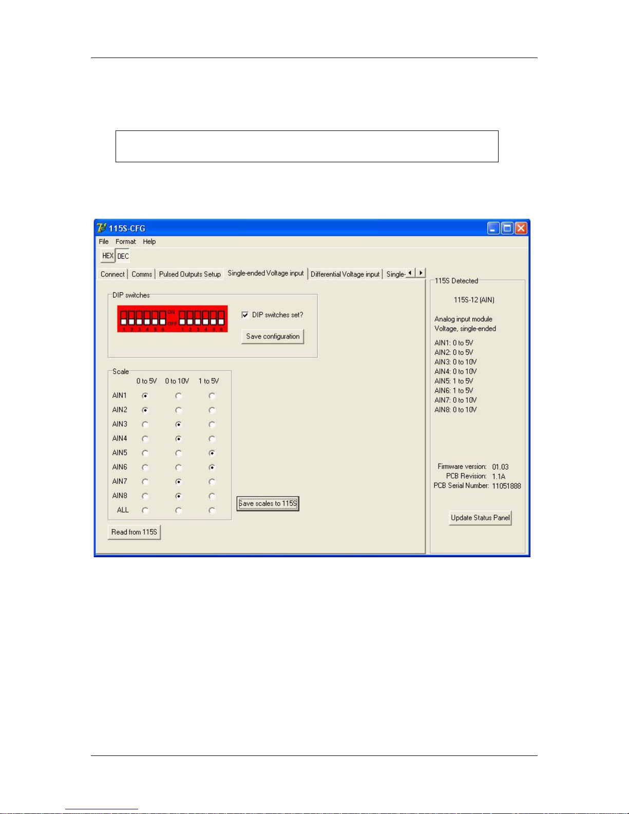
If the 115S-12 is to measure voltage with respect to ground, choose the Single-ended
voltage input page, as shown in Figure 4-5.
Remove the access panel from the front of the 115S-12 case to gain access
to the dip switches. Replace the access panel after setting the switches.
Set the switches according to the picture shown. The unit should be orientated with the
20-way connector towards you.
Figure 4-5: Setup page for single-ended voltage input.
Once the dip switches on the unit are set, tick the checkbox on the form, and click Save
configuration. Check the 115S Detected panel to ensure that the analog mode has been
updated (to Voltage, single-ended).
Clicking Read from 115S will read the scales out of the unit (if any) and display them in
the scales grid. Note that the dip switches should be set correctly for this result to be
relevant.
Choose the desired scale for each channel in the Scale box. Click the Save scales to 115S
button, and check that the scales are updated in the 115S Detected panel.
man_115S_1.14.docx Page 31
Page 32
115S Serial I/O Module User Manual
4.4.1.2 Differential voltage input
The 115S-12 can be configured to measure differential voltage. Neighbouring channels
serve as reference voltages in this mode. The four differential pairs are: AIN1-AIN2,
AIN3-AIN4, AIN5-AIN6, and AIN7-AIN8.
Note: If mapping Differential Voltage inputs using the Elpro E-Series Configuration
software only map the Odd inputs.
E.g. AIN1 for the first Differential input, AIN3 for the second, AIN5 for the third
and AIN7 for the fourth.
If using Modbus all registers can be read but only the odd registers holds the values,
i.e. 30001 for AIN1-AIN2, 30003 for AIN3-AIN4, 30005 for AIN5- AIN6 and 30007
for AIN7-AIN8.
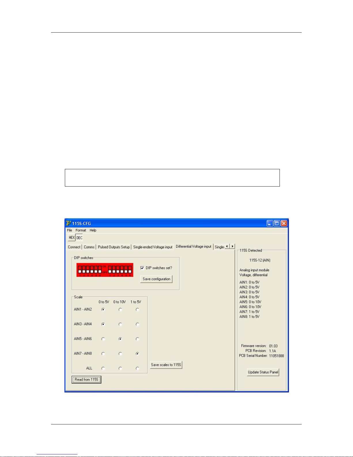
Choose the page to configure the 115S-12 for differential voltage input, as shown in
Figure 4-6.
Remove the access panel from the front of the 115S-12 case to gain access
to the dip switches. Replace the access panel after setting the switches.
Set the switches according to the picture shown. The unit should be orientated with the
20-way connector towards you.
Figure 4-6: Setup page for differential voltage input.
Page 32 June 2011
Page 33
115S Serial I/O Module User Manual
115S-12
115S-12
(mA)
105-G
(hex)
105-1
(mA)
105-3
(mA)
0 to 10mA
0
4000 4 4
10
C000
20
20
0 to 20mA
0
4000 4 4
20
C000
20
20
4 to 20mA
0
2000
0.5*
0
4
4000 4 4
20
C000
20
20
Once the dip switches on the unit are set, tick the checkbox on the form, and click Save
configuration. Check the 115S Detected panel to ensure that the analog mode has been
updated (to Voltage, differential).
Clicking Read from 115S will read the scales out of the unit (if any) and display them in
the scales grid. Note that the dip switches should be set correctly for this result to be
relevant.
Choose the desired scale for each channel in the Scale box. Click the Save scales to 115S
button, and check that the scales are updated in the 115S Detected panel.
4.4.2 Current input
Current inputs may be selected in the scales 0 to 10mA, 0 to 20mA, or 4 to 20mA. For
each scale, the minimum to maximum signal levels are represented by 4000 hex to C000
hex. Table 4-2 shows how the 115S-12 current readings translate to outputs in other
ELPRO products.
Current scale
Table 4-2: Compatibility of 115S-12 current inputs with other ELPRO products.
*
Reduced accuracy for less t ha n 4mA in 105-1.
Input current
Register value
Output current
Output current
man_115S_1.14.docx Page 33
Page 34
115S Serial I/O Module User Manual
4.4.2.1 Single-ended current input
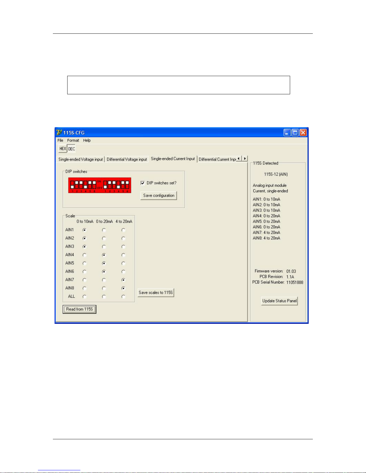
The 115S-12 can also measure current input. To measure current with respect to ground,
choose the Single-ended current input page, as shown in Figure 4-7.
Remove the access panel from the front of the 115S-12 case to gain access
to the dip switches. Replace the access panel after setting the switches.
Set the switches according to the picture shown. The unit should be orientated with the
20-way connector towards you.
Figure 4-7: Setup page for single-ended current input.
Once the dip switches on the unit are set, tick the checkbox on the form, and click Save
configuration. Check the 115S Detected panel to ensure that the analog mode has been
updated (to Current, single-ended).
Clicking Read from 115S will read the scales out of the unit (if any) and display them in
the scales grid. Note that the dip switches should be set correctly for this result to be
relevant.
Choose the desired scale for each channel in the Scale box. Click the Save scales to 115S
button, and check that the scales are updated in the 115S Detected panel.
Page 34 June 2011
Page 35
115S Serial I/O Module User Manual
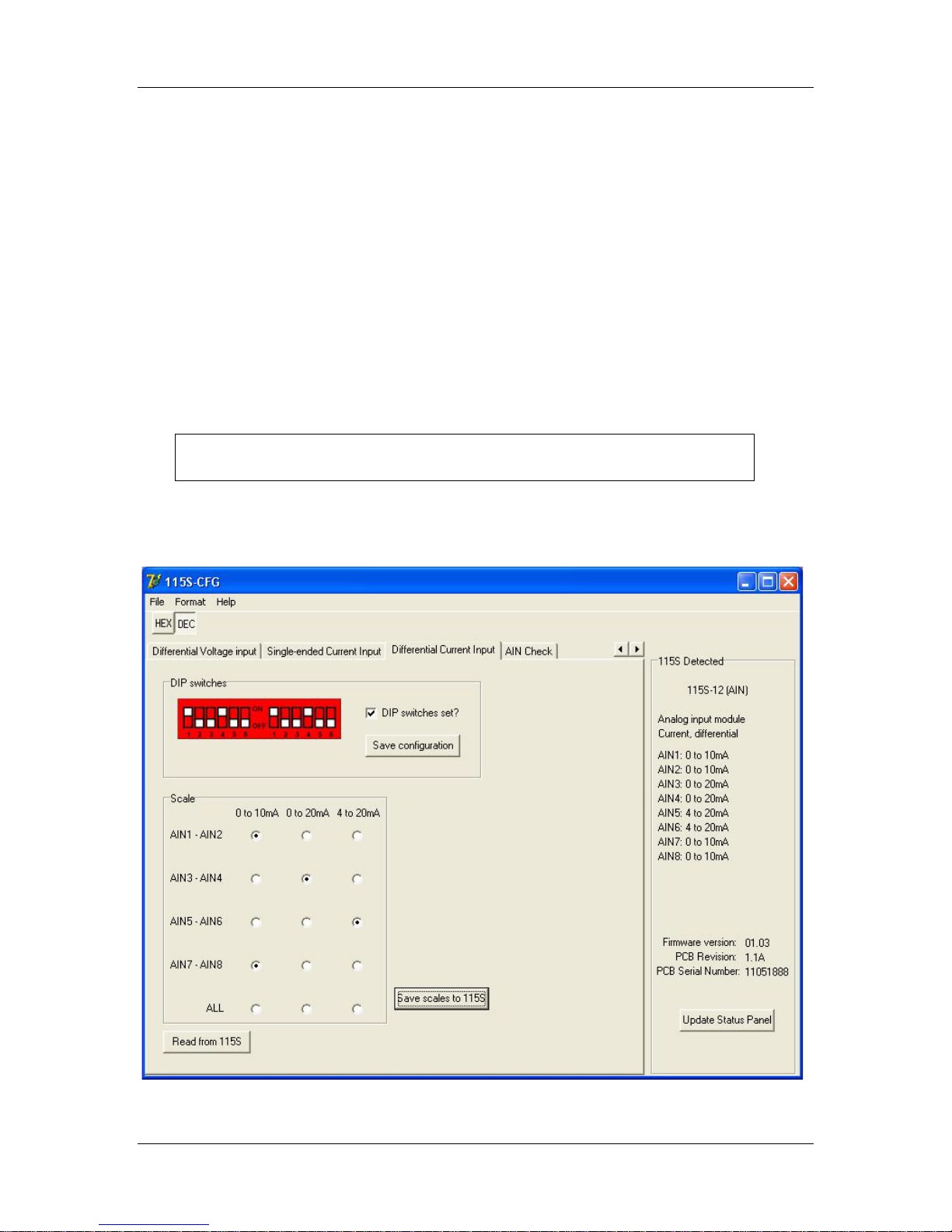
4.4.2.2 Differential current input
The 115S-12 can be configured to measure differential current. The differential pairs are:
AIN1-AIN2, AIN3-AIN4, AIN5-AIN6, and AIN7-AIN8. To use this configuration,
choose the differential current input page, as shown in Figure 4-8.
Note: If mapping Differential Analog inputs using the Elpro E-Series Configuration
software map only the Odd inputs.
E.g. AIN1 for the first Differential input, AIN3 for the second, AIN5 for the third
and AIN7 for the fourth.
If using Modbus all registers can be read but only the odd registers holds the values,
i.e. 30001 for AIN1-AIN2, 30003 for AIN3-AIN4, 30005 for AIN5- AIN6 and 30007
for AIN7-AIN8.
Remove the access panel from the front of the 115S-12 case to gain access
to the dip switches. Replace the access panel after setting the switches.
Set the switches according to the picture shown. The unit should be orientated with the
20-way connector towards you.
Figure 4-8: Setup page for differential current configuration.
man_115S_1.14.docx Page 35
Page 36
115S Serial I/O Module User Manual
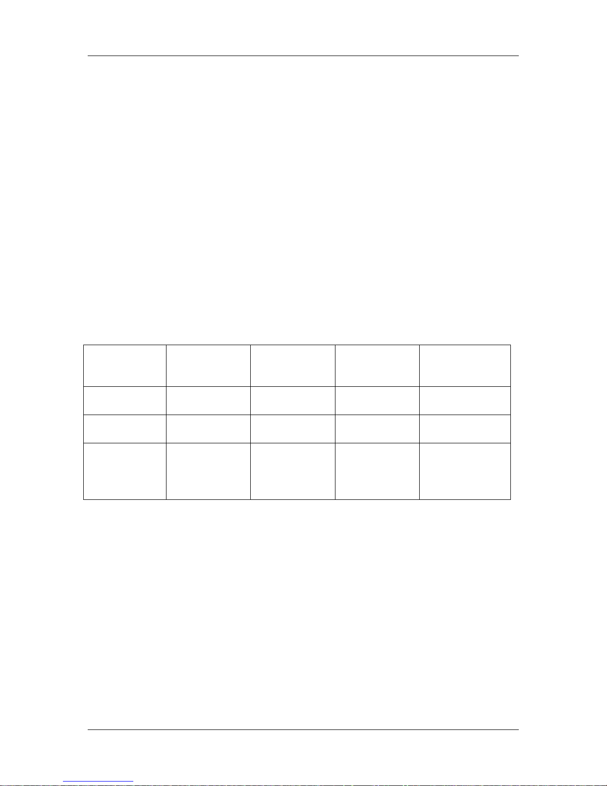
115S-13
105-1
(mA)
105-2
(mA)
105-G
(hex)
115S-13
(V)
0 to 5V
4 4 4000
0
20
20
C000
5
0 to 10V
4 4 4000
0
20
20
C000
10
1 to 5V
N/A*
0
2000 0 2*
2
3000
0.5 4 4
4000
1
20
20
C000
5
Once the dip switches on the unit are set, tick the checkbox on the form, and click Save
configuration. Check the 115S Detected panel to ensure that the analog mode has been
updated (to Current, differential).
Clicking Read from 115S will read the scales out of the unit (if any) and display them in
the scales grid. Note that the dip switches should be set correctly for this result to be
relevant.
Choose the desired scale for each channel in the Scale box. Click the Save scales to 115S
button, and check that the scales are updated in the 115S Detected panel.
4.5 115S-13 configuration
4.5.1 Voltage output
Voltage outputs may be selected in the scales 0 to 5V, 0 to 10V, or 1 to 5V. For each
scale, the minimum to maximum signal levels are represented by 4000 hex to C000 hex.
Table 4-3 shows how signals from other ELPRO products translate to 115S-13 voltage
levels.
Voltage scale
Table 4-3: Compatibility of other ELPRO products with 115S-13 voltage outputs.
*
Reduced accuracy for less than 4mA in 105-1.
Input current
Input current
Register value
Output voltage
Page 36 June 2011
Page 37
115S Serial I/O Module User Manual
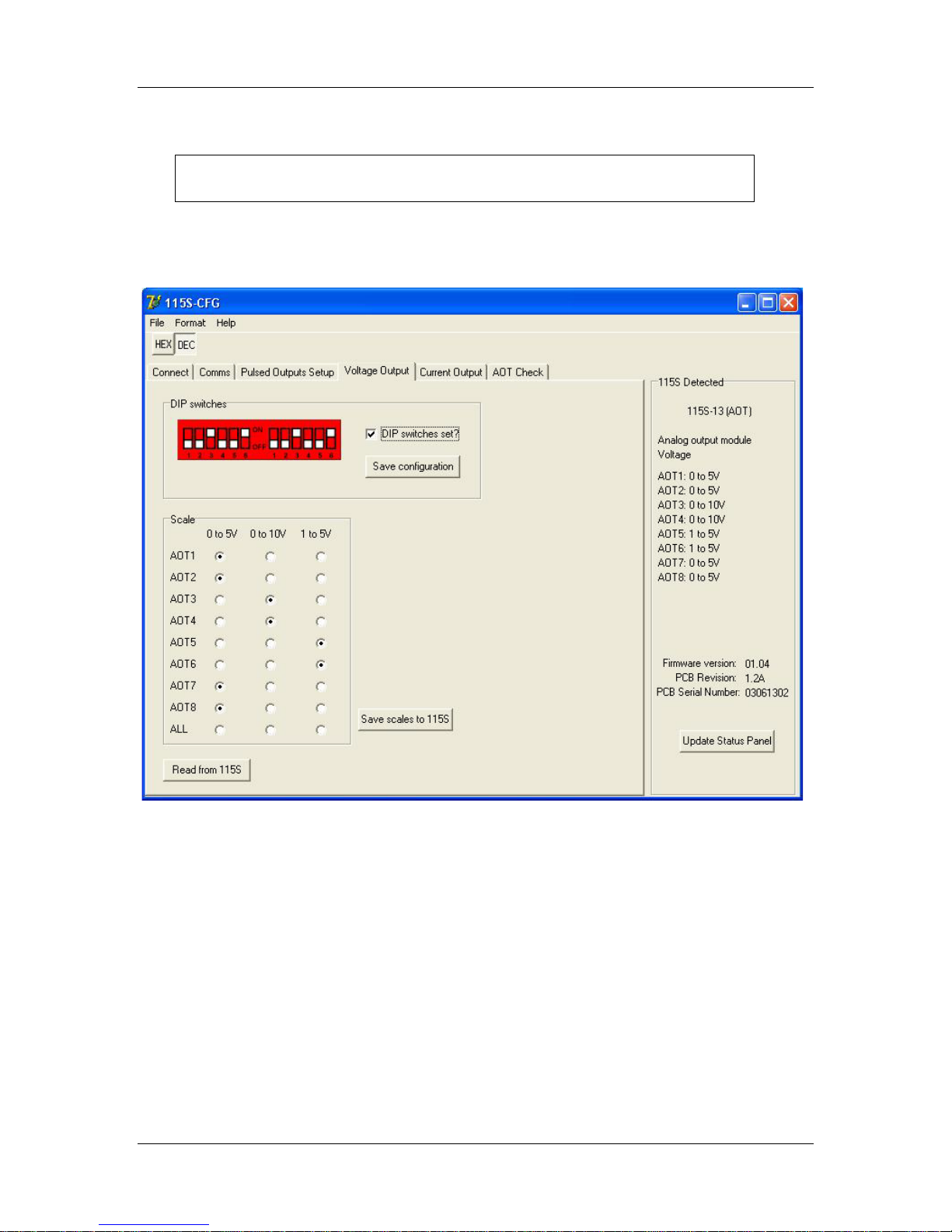
To configure the 115S-13 for voltage output, select the page as shown in Figure 4-9.
Remove the access panel from the front of the 115S-12 case to gain access
to the dip switches. Replace the access panel after setting the switches.
Set the switches according to the picture shown. The unit should be orientated with the
20-way connector towards you.
Figure 4-9: Voltage output setup page.
Once the dip switches on the unit are set, tick the checkbox on the form, and click Save
configuration. Check the 115S Detected panel to ensure that the analog mode has been
updated (to Voltage).
Clicking Read from 115S will read the scales out of the unit (if any) and display them in
the scales grid. Note that the dip switches should be set correctly for this result to be
relevant.
Choose the desired scale for each channel in the Scale box. Click the Save scales to 115S
button, and check that the scales are updated in the 115S Detected panel.
man_115S_1.14.docx Page 37
Page 38
115S Serial I/O Module User Manual
115S-13
105-1
(mA)
105-2
(mA)
105-G
(hex)
115S-13
(mA)
0 to 10mA
4 4 4000
0
20
20
C000
10
0 to 20mA
4 4 4000
0
20
20
C000
20
4 to 20mA
N/A*
0
2000
0
2*
2
3000 2 4 4 4000
4
20
20
C000
20
4.5.2 Current output
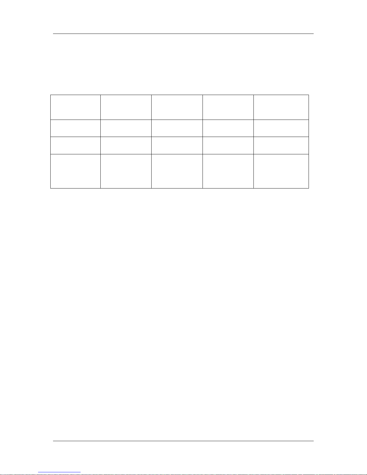
Current outputs may be selected in the scales 0 to 10mA, 0 to 20mA, or 4 to 20mA. For
each scale, the minimum to maximum signal levels are represented by 4000 hex to C000
hex. Table 4-4 shows how signals from other ELPRO products translate to 115S-13
current levels.
Current scale
Table 4-4: Compatibility of other ELPRO products with 115S-13 voltage outputs.
*
Reduced accuracy for less than 4mA in 105-1.
Input current
Input current
Register value
Output current
Page 38 June 2011
Page 39
115S Serial I/O Module User Manual
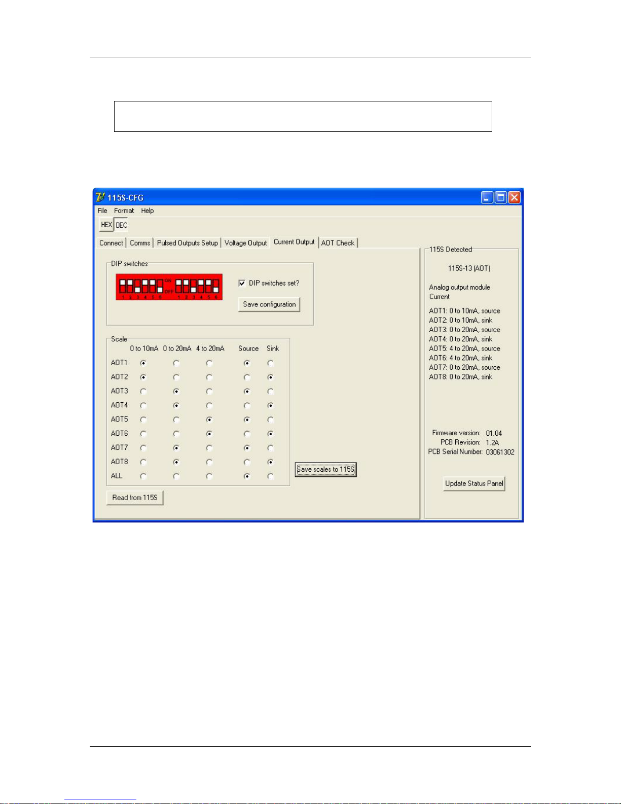
To configure the 115S-13 for current output, select the page as shown in Figure 4-10.
Remove the access panel from the front of the 115S-12 case to gain access
to the dip switches. Replace the access panel after setting the switches.
Set the switches according to the picture shown. The unit should be orientated with the
20-way connector towards you.
Figure 4-10: Current output setup page.
Once the dip switches on the unit are set, tick the checkbox on the form, and click Save
configuration. Check the 115S Detected panel to ensure that the analog mode has been
updated (to Current).
Clicking Read from 115S will read the scales out of the unit (if any) and display them in
the scales grid. Note that the dip switches should be set correctly for this result to be
relevant.
Choose the desired scale for each channel in the Scale box. Click the Save scales to 115S
button, and check that the scales are updated in the 115S Detected panel.
man_115S_1.14.docx Page 39
Page 40
115S Serial I/O Module User Manual
DIO
DIO
DIO
DIO
DIO
DIO
DIO
DIO
DIO
DIO
DIO
DIO
DIO
DIO
DIO
DIO
5 Operation
5.1 115S-11 module
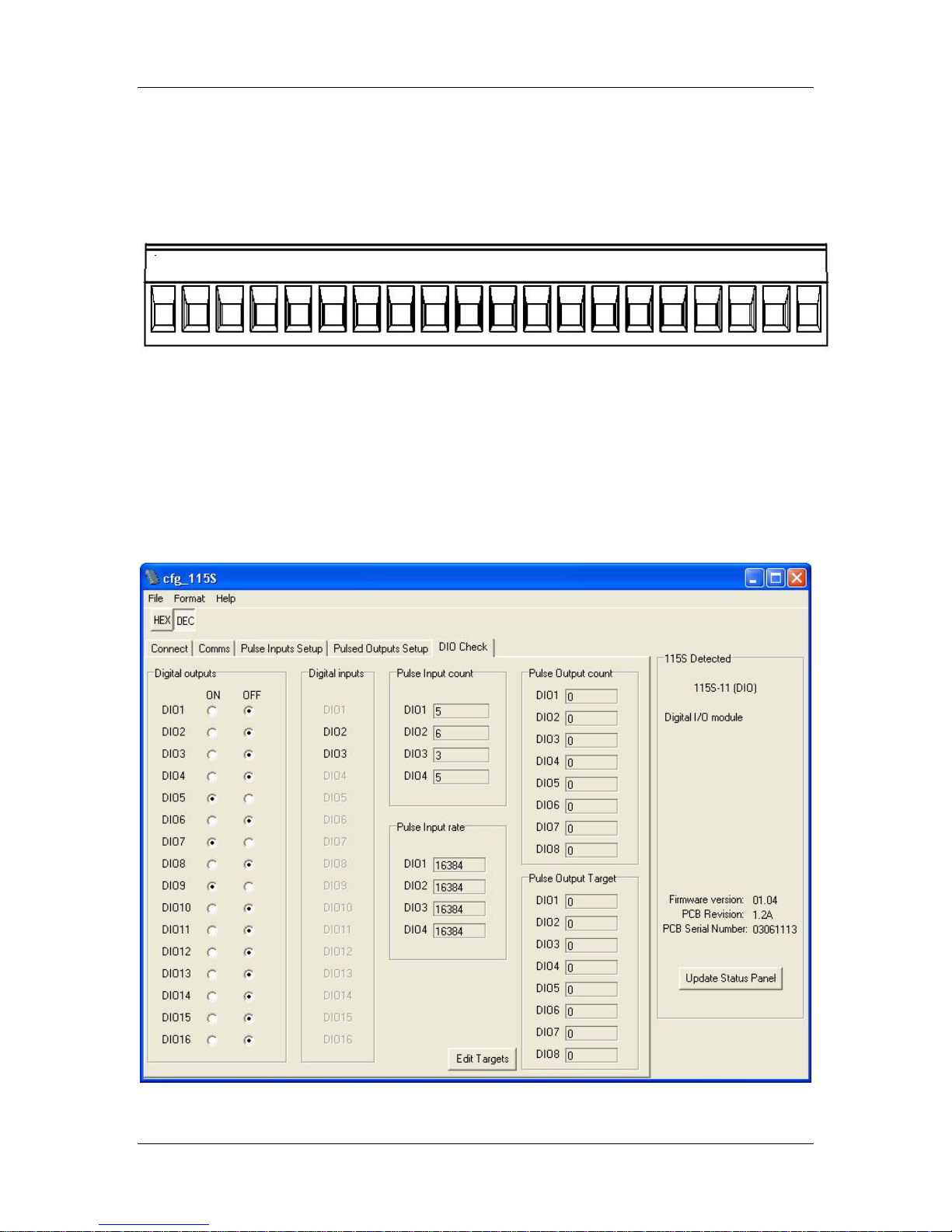
The I/O terminal block for the 115S-11 is shown in Figure 5-1.
1 2 3 4 5 6 7 8 Earth Earth 9 10 11 12 13 14 15 16 Earth Earth
Figure 5-1: I/O terminal block for 115S-11.
Pulse inputs coincide with DIO terminals 1-4. Pulse outputs coincide with DIO terminals
1-8.
The operation of the digital I/O may be confirmed using the configuration software. Start
the software as described in section 4, and choose the DIO Check page as shown in
Figure 5-2.
Figure 5-2: Check the operation of the 115S-11 module using the DIO Check page.
Page 40 June 2011
Page 41
115S Serial I/O Module User Manual
DIO
DIO
DIO
DIO
DIO
DIO
DIO
DIO ALS
AI+1
AI-1
AI+2
AI-2
AI+3
AI-3
AI+4
AI-4 A ALS
Test the digital outputs by setting the select-buttons to ON or OFF - this will force the
DO to the selected state.
Digital inputs are reflected in the software by blacking (ON) or greying (OFF) of the
associated label in the Digital Inputs column.
The pulsed input count values are shown, as well as the pulse rate. The rate can be
viewed in decimal or hexadecimal and represents a fraction of the maximum pulse rate,
where hex 4000 is 0% and hex C000 is 100% of the maximum pulse rate.
The pulse output count values are also shown. The pulse out target may be set by clicking
the Edit Targets button. Pulses will be produced until the count reaches the target.
5.2 115S-12 module
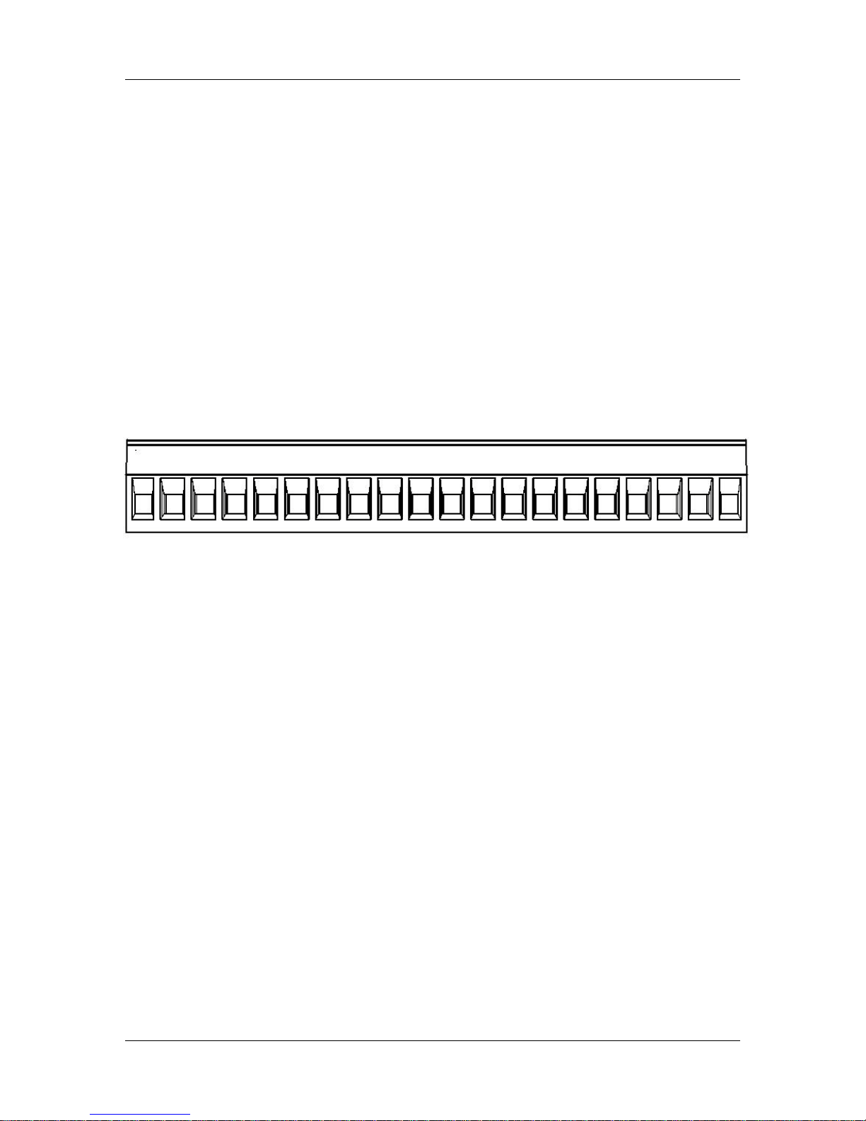
The I/O terminal block for the 115S-12 is shown in Figure 5-3.
1 2 3 4 5 6 7 8 Earth +24 AI 1 AI 2 AI 3 AI 4 AI 5 AI 6 AI 7 AI 8 GND +24
Figure 5-3: I/O terminal block for 115S-12.
Pulse outputs coincide with DIO terminals 1-8.
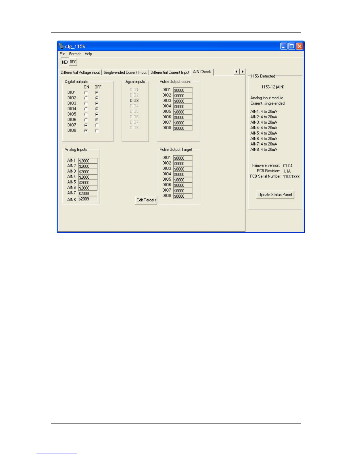
The operation of the 115S-12 may be confirmed using the configuration software. Start
the software as described in section 4, and choose the AIN Check page as shown in Figure
5-4.
man_115S_1.14.docx Page 41
Page 42
115S Serial I/O Module User Manual
Figure 5-4: Check the operation of the 115S-12 module with the AIN Check page.
Test the digital outputs by setting the select-buttons to ON or OFF - this will force the
DO to the selected state.
Digital inputs are reflected in the software by blacking (ON) or greying (OFF) of the
associated label in the Digital Inputs column.
The pulse output count values are also shown. The pulse out target may be set by clicking
the Edit Targets button. Pulses will be produced until the count reaches the target.
The analog inputs can be viewed in decimal or hexadecimal and represents a fraction of
the analog signal, where hex 4000 is 0% and hex C000 is 100%.
In differential configuration, only the value of the first channel in the differential pair
shows the quantity being measured. The second channel of each differential pair should
be ignored.
Page 42 June 2011
Page 43
115S Serial I/O Module User Manual
DIO
DIO
DIO
DIO
DIO
DIO
DIO
DIO ALS
AOT
AOT
AOT
AOT
AOT
AOT
AOT
AOT A ALS
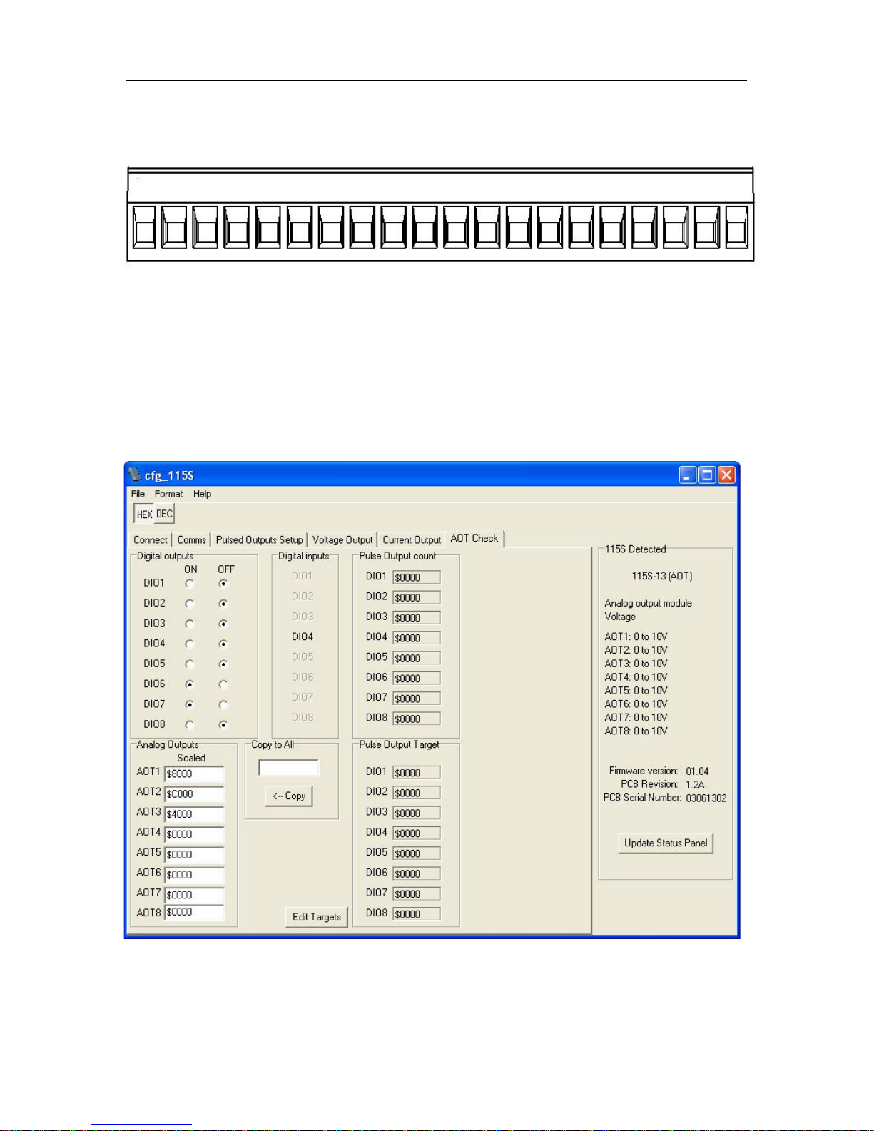
1 2 3 4 5 6 7 8 Earth
+24 1 2 3 4 5 6 7 8
GND
+24
5.3 115S-13 module
The I/O terminal block for the 115S-13 is shown in Figure 5-5.
Figure 5-5: I/O terminal block for 115S-13.
Pulse outputs coincide with DIO terminals 1-8.
The operation of the 115S-13 may be confirmed using the configuration software. Start
the software as described in chapter 4, and choose the AOT Check page.
Figure 5-6: Check the operation of the 115S-13 module using the AOT Check page.
man_115S_1.14.docx Page 43
Page 44

115S Serial I/O Module User Manual
Test the digital outputs by setting the select-buttons to ON or OFF - this will force the
DO to the selected state.
Digital inputs are reflected in the software by blacking (ON) or greying (OFF) of the
associated label in the Digital Inputs column.
The pulse output count values are also shown. The pulse out target may be set by clicking
the Edit Targets button. Pulses will be produced until the count reaches the target.
The analog outputs can be viewed in decimal or hexadecimal and represents a fraction of
the analog signal, where hex 4000 is 0% and hex C000 is 100%.
The analog output values can be set by the user for testing, and the output signal
measured to confirm the analog operation. If you are using hexadecimal values (which is
the easiest) ensure the $ symbol precedes the value to denote a hex number.
Page 44 June 2011
Page 45
115S Serial I/O Module User Manual
Voltage scale
Current scale
Hex
value
Percent
Dec
value
0-5V
0-10V
1-5V
0-10mA
0-20mA
4-20mA
0000
0.00%
0
N/A
N/A
N/A
N/A
N/A
N/A
0800
3.13%
2048
N/A
N/A
N/A
N/A
N/A
N/A
1000
6.25%
4096
N/A
N/A
N/A
N/A
N/A
N/A
1800
9.38%
6144
N/A
N/A
N/A
N/A
N/A
N/A
2000
12.50%
8192
N/A
N/A
0.00
N/A
N/A
0.00
2800
15.63%
10240
N/A
N/A
0.25
N/A
N/A
1.00
3000
18.75%
12288
N/A
N/A
0.50
N/A
N/A
2.00
3800
21.88%
14336
N/A
N/A
0.75
N/A
N/A
3.00
4000
25.00%
16384
0.00
0.00
1.00
0.00
0.00
4.00
4800
28.13%
18432
0.31
0.63
1.25
0.63
1.25
5.00
5000
31.25%
20480
0.63
1.25
1.50
1.25
2.50
6.00
5800
34.38%
22528
0.94
1.88
1.75
1.88
3.75
7.00
6000
37.50%
24576
1.25
2.50
2.00
2.50
5.00
8.00
6800
40.63%
26624
1.56
3.13
2.25
3.13
6.25
9.00
7000
43.75%
28672
1.88
3.75
2.50
3.75
7.50
10.00
7800
46.88%
30720
2.19
4.38
2.75
4.38
8.75
11.00
8000
50.00%
32768
2.50
5.00
3.00
5.00
10.00
12.00
8800
53.13%
34816
2.81
5.63
3.25
5.63
11.25
13.00
9000
56.25%
36864
3.13
6.25
3.50
6.25
12.50
14.00
9800
59.38%
38912
3.44
6.88
3.75
6.88
13.75
15.00
A000
62.50%
40960
3.75
7.50
4.00
7.50
15.00
16.00
A800
65.63%
43008
4.06
8.13
4.25
8.13
16.25
17.00
B000
68.75%
45056
4.38
8.75
4.50
8.75
17.50
18.00
B800
71.88%
47104
4.69
9.38
4.75
9.38
18.75
19.00
C000
75.00%
49152
5.00
10.00
5.00
10.00
20.00
20.00
C800
78.13%
51200
5.31
10.63
5.25
10.63
21.25
21.00
D000
81.25%
53248
5.63
11.25
5.50
11.25
22.50
22.00
D800
84.38%
55296
5.94
11.88
5.75
11.88
23.75
23.00
E000
87.50%
57344
6.25
12.50
6.00
12.50
N/A
24.00
E800
90.63%
59392
6.56
13.13
6.25
13.13
N/A
N/A
F000
93.75%
61440
6.88
13.75
6.50
13.75
N/A
N/A
5.4 Hexadecimal representation of voltage and current levels
The voltage and current levels are represented as a fraction of the configured scale. 4000
hex represents the minimum level in the scale, and C000 hex represents the maximum
level in the scale.
Levels and their hex representation are summarised in Table 5-1 for easy reference.
Table 5-1: Hex representation of voltage and current levels.
man_115S_1.14.docx Page 45
Page 46
115S Serial I/O Module User Manual
Data
Modbus I/O Type
Modbus
Addresses
Digital input 1
Input status
10001
Digital input 2
Input status
10002
Digital input 3
Input status
10003
Digital input 4
Input status
10004
Digital input 5
Input status
10005
Digital input 6
Input status
10006
Digital input 7
Input status
10007
Digital input 8
Input status
10008
Digital input 9
Input status
10009
Digital input 10
Input status
10010
Digital input 11
Input status
10011
Digital input 12
Input status
10012
Digital input 13
Input status
10013
Digital input 14
Input status
10014
Digital input 15
Input status
10015
Digital input 16
Input status
10016
Digital output 1
Coil status
00001
Digital output 2
Coil status
00002
Digital output 3
Coil status
00003
Digital output 4
Coil status
00004
Digital output 5
Coil status
00005
Digital output 6
Coil status
00006
Digital output 7
Coil status
00007
Digital output 8
Coil status
00008
Digital output 9
Coil status
00009
Digital output 10
Coil status
00010
Digital output 11
Coil status
00011
Digital output 12
Coil status
00012
Digital output 13
Coil status
00013
Digital output 14
Coil status
00014
Digital output 15
Coil status
00015
Digital output 16
Coil status
00016
Pulse input count 1
Input registers
30017 – 30018
Pulse input count 2
Input registers
30019 – 30020
Pulse input count 3
Input registers
30021 – 30022
Pulse input count 4
Input registers
30023 – 30024
Pulse input rate 1
Input registers
30001
Pulse input rate 2
Input registers
30002
Pulse input rate 3
Input registers
30003
Appendix A. Modbus address map
A.1. 115S-11
Page 46 June 2011
Page 47
115S Serial I/O Module User Manual
Data
Modbus I/O Type
Modbus
Addresses
Pulse input rate 4
Input registers
30004
Maximum input pulse rate 1
Input registers
30101
Maximum input pulse rate 2
Input registers
30102
Maximum input pulse rate 3
Input registers
30103
Maximum input pulse rate 4
Input registers
30104
Pulse output count 1
Input registers
30009
Pulse output count 2
Input registers
30010
Pulse output count 3
Input registers
30011
Pulse output count 4
Input registers
30012
Pulse output count 5
Input registers
30013
Pulse output count 6
Input registers
30014
Pulse output count 7
Input registers
30015
Pulse output count 8
Input registers
30016
Pulse output target 1
Holding registers
40009
Pulse output target 2
Holding registers
40010
Pulse output target 3
Holding registers
40011
Pulse output target 4
Holding registers
40012
Pulse output target 5
Holding registers
40013
Pulse output target 6
Holding registers
40014
Pulse output target 7
Holding registers
40015
Pulse output target 8
Holding registers
40016
Modbus Output Timeout
Holding registers
40204
Pulse out update time 1
Input registers
30109
Pulse out update time 2
Input registers
30110
Pulse out update time 3
Input registers
30111
Pulse out update time 4
Input registers
30112
Pulse out update time 5
Input registers
30113
Pulse out update time 6
Input registers
30114
Pulse out update time 7
Input registers
30115
Pulse out update time 8
Input registers
30116
Module supply voltage*
Input registers
30033
Serial port transmission mode
Input registers
30201
Serial port baud rate
Input registers
30202
Serial port parity and stop bit
Input registers
30203
Modbus Comms Fail Timeout
!
Input registers
30204
ELPRO ACK Timeout
!
Input registers
30205
Module Firmware version%
Input Register
30801
*
0x4000 = 8V; 0xC000 = 40V (Firmware earlier than 2.00 is 0x4000 = 8V; 0xC000 = 16V
!
Timeout values in 32mSec increments
%
0x0204 = Ver 2.04
man_115S_1.14.docx Page 47
Page 48
115S Serial I/O Module User Manual
Data
Modbus I/O Type
Modbus
Addresses
Digital input 1
Input status
10001
Digital input 2
Input status
10002
Digital input 3
Input status
10003
Digital input 4
Input status
10004
Digital input 5
Input status
10005
Digital input 6
Input status
10006
Digital input 7
Input status
10007
Digital input 8
Input status
10008
Digital output 1
Coil status
00001
Digital output 2
Coil status
00002
Digital output 3
Coil status
00003
Digital output 4
Coil status
00004
Digital output 5
Coil status
00005
Digital output 6
Coil status
00006
Digital output 7
Coil status
00007
Digital output 8
Coil status
00008
Pulse output count 1
Input registers
30009
Pulse output count 2
Input registers
30010
Pulse output count 3
Input registers
30011
Pulse output count 4
Input registers
30012
Pulse output count 5
Input registers
30013
Pulse output count 6
Input registers
30014
Pulse output count 7
Input registers
30015
Pulse output count 8
Input registers
30016
Pulse output target 1
Holding registers
40009
Pulse output target 2
Holding registers
40010
Pulse output target 3
Holding registers
40011
Pulse output target 4
Holding registers
40012
Pulse output target 5
Holding registers
40013
Pulse output target 6
Holding registers
40014
Pulse output target 7
Holding registers
40015
Pulse output target 8
Holding registers
40016
Modbus Output Timeout
Holding registers
40204
Pulse out update time 1
Input registers
30109
Pulse out update time 2
Input registers
30110
Pulse out update time 3
Input registers
30111
Pulse out update time 4
Input registers
30112
Pulse out update time 5
Input registers
30113
Pulse out update time 6
Input registers
30114
Pulse out update time 7
Input registers
30115
Pulse out update time 8
Input registers
30116
A.2. 115S-12
Page 48 June 2011
Page 49
115S Serial I/O Module User Manual
Data
Modbus I/O Type
Modbus
Addresses
Analog inputs 1
Input registers
30001
Analog inputs 2
Input registers
30002
Analog inputs 3
Input registers
30003
Analog inputs 4
Input registers
30004
Analog inputs 5
Input registers
30005
Analog inputs 6
Input registers
30006
Analog inputs 7
Input registers
30007
Analog inputs 8
Input registers
30008
Module supply voltage*
Input registers
30033
Analog supply voltage (24V)+
Input registers
30034
Serial port transmission mode
Input registers
30201
Serial port baud rate
Input registers
30202
Serial port parity and stop bit
Input registers
30203
Modbus Comms Fail Timeout
!
Input registers
30204
ELPRO ACK Timeout
!
Input registers
30205
Module Firmware version%
Input Register
30801
*
0x4000 = 8V; 0xC000 = 40V (Firmware earlier than 2.00 is 0x4000 = 8V; 0xC000 = 16V
+
0x4000 =12V; 0xC000 = 36V
!
Timeout values in 32mSec increments
%
0x0204 = Ver 2.04
Note: If using Differential Voltage or Current inputs, only the odd inputs should be
used, i.e. AIN1 for the first input, AIN3 for the second, AIN5 for the third and AIN7
for the fourth.
man_115S_1.14.docx Page 49
Page 50
115S Serial I/O Module User Manual
Data
Modbus I/O Type
Modbus
Addresses
Digital input 1
Input status
10001
Digital input 2
Input status
10002
Digital input 3
Input status
10003
Digital input 4
Input status
10004
Digital input 5
Input status
10005
Digital input 6
Input status
10006
Digital input 7
Input status
10007
Digital input 8
Input status
10008
Digital output 1
Coil status
00001
Digital output 2
Coil status
00002
Digital output 3
Coil status
00003
Digital output 4
Coil status
00004
Digital output 5
Coil status
00005
Digital output 6
Coil status
00006
Digital output 7
Coil status
00007
Digital output 8
Coil status
00008
Pulse output count 1
Input registers
30009
Pulse output count 2
Input registers
30010
Pulse output count 3
Input registers
30011
Pulse output count 4
Input registers
30012
Pulse output count 5
Input registers
30013
Pulse output count 6
Input registers
30014
Pulse output count 7
Input registers
30015
Pulse output count 8
Input registers
30016
Pulse output target 1
Holding registers
40009
Pulse output target 2
Holding registers
40010
Pulse output target 3
Holding registers
40011
Pulse output target 4
Holding registers
40012
Pulse output target 5
Holding registers
40013
Pulse output target 6
Holding registers
40014
Pulse output target 7
Holding registers
40015
Pulse output target 8
Holding registers
40016
Modbus Output Timeout
Holding registers
40204
Pulse out update time 1
Input registers
30109
Pulse out update time 2
Input registers
30110
Pulse out update time 3
Input registers
30111
Pulse out update time 4
Input registers
30112
Pulse out update time 5
Input registers
30113
Pulse out update time 6
Input registers
30114
Pulse out update time 7
Input registers
30115
Pulse out update time 8
Input registers
30116
Analog outputs 1
Holding registers
40001
A.3. 115S-13
Page 50 June 2011
Page 51
115S Serial I/O Module User Manual
Data
Modbus I/O Type
Modbus
Addresses
Analog outputs 2
Holding registers
40002
Analog outputs 3
Holding registers
40003
Analog outputs 4
Holding registers
40004
Analog outputs 5
Holding registers
40005
Analog outputs 6
Holding registers
40006
Analog outputs 7
Holding registers
40007
Analog outputs 8
Holding registers
40008
Module supply voltage*
Input registers
30033
Analog supply voltage (28V) +
Input registers
30034
Serial port transmission mode
Input registers
30201
Serial port baud rate
Input registers
30202
Serial port parity and stop bit
Input registers
30203
Modbus Comms Fail Timeout
!
Input registers
30204
ELPRO ACK Timeout
!
Input registers
30205
Module Firmware version%
Input Register
30801
*
0x4000 = 8V; 0xC000 = 40V (Firmware earlier than 2.00 is 0x4000 = 8V; 0xC000 = 16V
+
0x4000 =12V; 0xC000 = 36V
!
Timeout values in 32mSec increments
%
0x0204 = Ver 2.04
man_115S_1.14.docx Page 51
Page 52

115S Serial I/O Module User Manual
Function
code
Description
Maximum Data Size
1,2
Read coil / input status
1160 coils / inputs
3
Read holding (output) registers
145 registers
4
Read input registers
145 registers
5
Force single coil
1 coil
6
Set single register
1 register
7
Read exception status
8 coils
8
Loopback test
N/A
9,10
NOT SUPPORTED
NOT SUPPORTED
11
Communications event counter
N/A
12-14
NOT SUPPORTED
NOT SUPPORTED
15
Force multiple coils
1160 coils
16
Set multiple registers
145 registers
17-255
NOT SUPPORTED
NOT SUPPORTED
Appendix B. Modbus Functionality
Table B-1 specifies the maximum query and response data parameters for the 115S
modules. See the Gould Modbus Protocol Reference guide (PI-MBUS 300 Rev B) for
more detail.
Table B-1: Supported Modbus functions and limitations for 115S modules.
Page 52 June 2011
Page 53

115S Serial I/O Module User Manual
Address
Description
40201
Serial port transmission mode
Appendix C. Comms Recovery
If the communications setting of the 115S has been forgotten or mistakenly set, there is a
way of recovering serial communications with the 115S. 115S firmware versions 1.04
and earlier require ModScan to do this. With later firmware versions, this can be done
using the configuration software, cfg_115S_Vx.xx.exe.
Procedure for recovering communications with recent firmware (V1.05 and later):
1. Set the Modbus address switches to 00. This fixes the communications setting to
Modbus RTU, 9600 baud, no parity, and one stop bit.
2. Connect a standard (straight-through) RS232 cable to the module and the PC.
3. Start the configuration software, cfg_115S_Vx.xx.exe.
4. Set the slave address to 100.
5. Ensure the comms settings are 9600 baud, no parity, one stop bit.
6. Click Connect to 115S
7. The module should connect successfully.
8. Choose the Comms page and change the settings to the desired parameters.
9. If the module did not connect successfully, try the steps listed below for using
ModScan.
Procedure for recovering communications with firmware V1.04 and earlier:
1. Set the Modbus address switches to 00. This fixes the communications setting to
those specified in step 6.
2. Connect the RS232 port to the PC and start ModScan.
3. Supply power to the 115S.
4. In ModScan, set the following
- Address: 0201
- Length: 3
- Device ID: 100
- Modbus Point Type: Holding register
5. Click Connection / Connect.
6. Choose the appropriate COM port. Also choose
- Baud rate: 9600
- Word length: 8
- Parity: none
- Stop bits: 1
7. Click Protocol Selection. Choose STANDARD ASCII for Transmission mode. Click
OK, OK.
8. ModScan should connect to the module with no errors.
9. The registers displayed in ModScan represent the serial port settings that are used
when the address switches are set to other than 00, as follows:
man_115S_1.14.docx Page 53
Page 54
115S Serial I/O Module User Manual
40202
Serial port baud rate
40203
Serial port parity and stop bit
Setting
Register Value
Modbus RTU
0x0101
Modbus ASCII, 8 data bits
0x0201
Modbus ASCII, 7 data bits
0x0202
Setting
Register Value
1200
0x000C
2400
0x0018
4800
0x0030
9600
0x0060
14400
0x0090
19200
0x00C0
28800
0x0120
38400
0x0180
57600
0x0240
76800
0x0300
115200
0x0480
Parity Setting
Register’s High Byte Value
None
0x00
Odd
0x11
Even
0x22
Stop-bit Setting
Register’s Low Byte Value
1 stop bit
0x11
2 stop bits
0x22
10. Use the tables below to work out the current communications settings, or write to the
registers using ModScan to change the settings to the desired values. Note that the
module transmission mode should be set to Modbus RTU.
Modbus address 40201, serial port transmission mode:
Modbus address 40202, serial port baud rate:
Modbus address 40203, serial port parity and stop bit:
11. Once the new comms setting are correct, be sure to change the address switches back
to a non-zero setting for normal operation.
Page 54 June 2011
Page 55
115S Serial I/O Module User Manual
EMC Approval
EN 55024:1998
FCC Part 15
Operating temperature
range
-40 to +60 deg C
Power supply
10.8 – 30.0 VDC
Model Dependent. Check
operating voltages
Supply current (idle 13.8V)
Supply current for I/O
per analog output
50mA
If using 24V loop supply
Loop supply
24V nominal *
* Loop supply will follow
voltage above 24V input.
Loop supply max current
115S-12 : 270mA
115S-13 : 160mA
RS232 port
Modbus protocol
RS485 port
Modbus protocol
ELPRO E-Series protocol
Modbus protocol
Transmission modes
Modbus ASCII 8 data bits
** If no parity, use 2 stop
Baud rates
1200; 2400; 4800; 9600;
115,200
Parity
Odd, even, none
Stop bits
1, 2
Slave address
Modbus = 01-99
Elpro = 96 - 127. Note:
modules per radio is 10.
Appendix D. Specifications
EN 61000-3-2: 2002
EN 61000-3-3: 2002
EN 55022: 1998
-11
-12
-13
per digital input
per digital output
per analog input
13.8V / 24VDC nom
100mA
100mA
120mA
13mA
13mA
50mA
rear label for actual
115S-xx power supply
man_115S_1.14.docx Page 55
Modbus ASCII 7 data
bits**
Modbus RTU
14,400; 19,200; 28,800;
38,400; 57,600; 76,800;
bits. If using parity, use 1
stop bit.
Each module requires 3
addresses meaning the
maximum number of serial
Page 56
115S Serial I/O Module User Manual
Default settings
If slave address = 0
Modbus RTU, 9600, N, 1
Digital inputs
On-state voltage
<2.1VDC
Wetting current
5mA
Max pulse input rate
1kHz
Minimum pulse width
0.5mS
Max pulse input count
4294967295 (32-bit)
Digital outputs
Output voltage range
0-30VDC
Output current max
200mA
Max pulse output rate
50Hz
Max pulse output count
65535
Analog Inputs
Input voltage range
0-12V
Voltage resolution
16 bits
Input current range
0-24mA
Current resolution
16 bits
Input impedance (voltage)
100k
Input impedance (current)
100ohm
Common mode voltage
27VDC
Calibrated accuracy
0.10%
Analog Outputs
Output voltage range
0-12V
Voltage resolution
12 bits
Output current range
0-24mA
Total output current 160mA
Current resolution
12 bits
Calibrated accuracy
0.10%
115S
-11
-12
-13
Digital inputs/outputs
16 8 8
Pulse outputs
8 8 8
Pulse inputs
4 - -
Analog inputs
- 8 -
Analog outputs
- - 8
range
Table D-1: 115S Specifications.
Table D-2: 115S module types and I/O.
Page 56 June 2011
Page 57
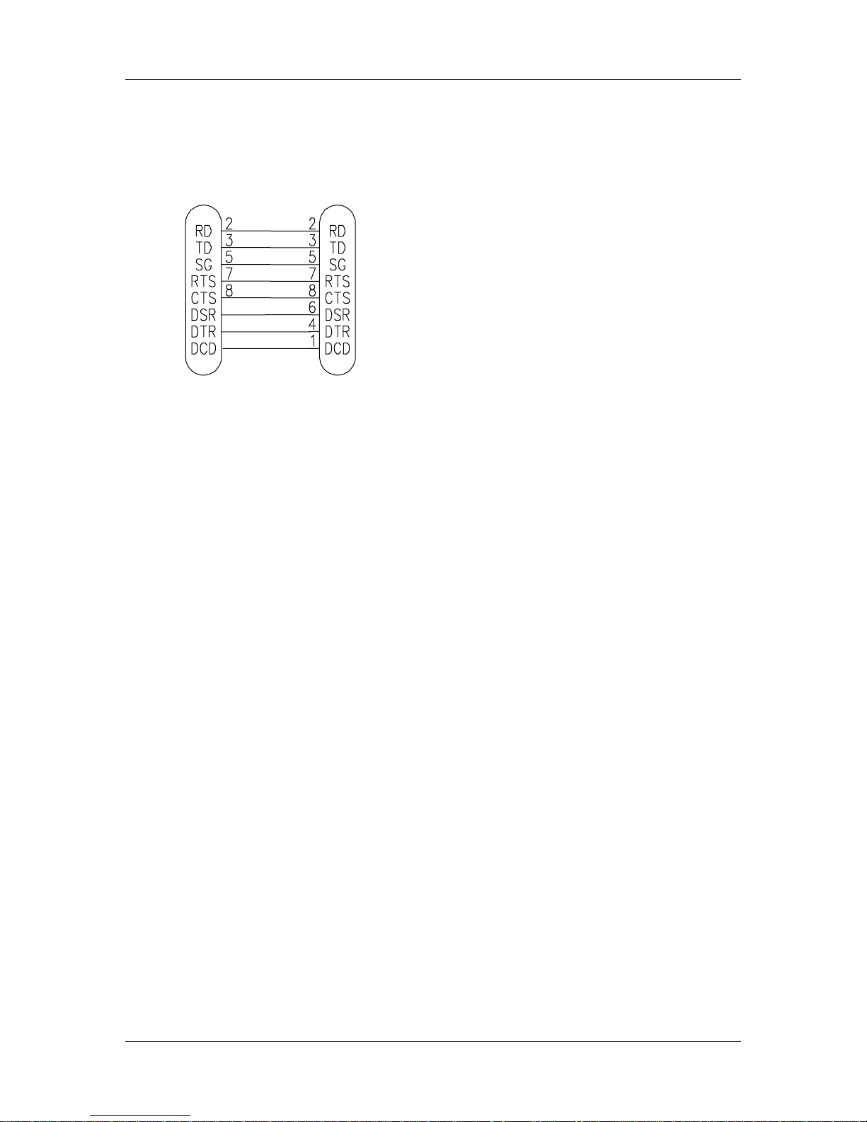
115S Serial I/O Module User Manual
115S
DB9
MALE
PC
DB9
FEMALE
Appendix E. RS232 Wiring
The RS232 connection to the 115S modules requires a standard straight-through serial
cable (modem cable). The wiring is shown in Figure E-1.
Figure E-1: Wiring for RS232 cable for PC-115S communications.
man_115S_1.14.docx Page 57
 Loading...