

ELPROG PULSAR 2 User Manual
15.09.2008
PULSAR 2 v 2.15
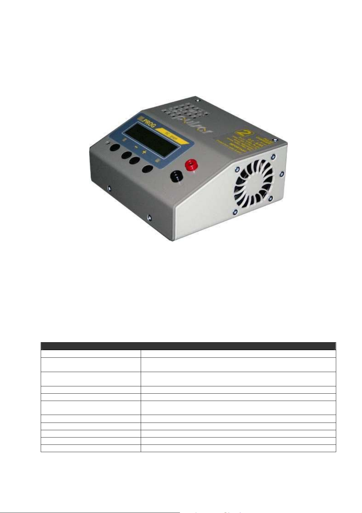
PULSAR 2 is a fast, microcontroller-based charger suitable for use with various types of batteries. Special design of
hardware and software makes it possible to charge batteries with high currents without risk of damage and in some
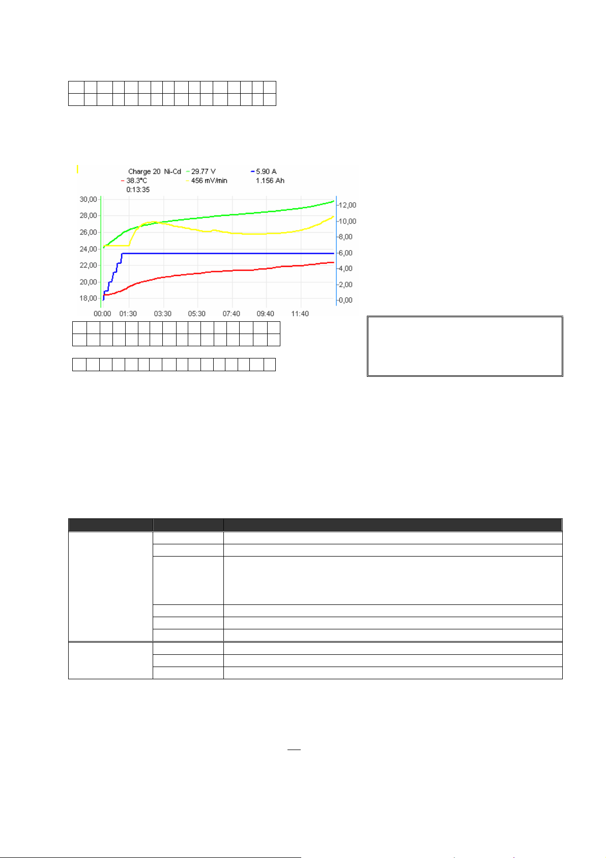
cases even improving their durability. During charging process all important parameters are displayed on LCD and
transmitted via serial port (RS232) to a desktop computer. Additional software allows visualization of changes in
voltage, current, voltage time derivative and temperature during whole charging process which allows user to
determine precisely status of batteries and decide whether they need conditioning or not. A data communication
between Pulsar 2 and Pulsar-EQUAL Equalizer (Balancer) is possible and increases the safety of working with Li-Xx
packs.
Technical specification
Battery types supported Ni-Cd, Ni-MH, Pb-bat, RAM, Li-Ion, Li-Pol, Li-Ta, Li-Ph (Li-Ion FePO4)
Supply voltage 10 – 16V DC (car battery min 30Ah (70Ah recommended) or power supply
14V/30A)
Low voltage alarm level (alarm) min 10 – 11,5V adjustable in Setup
max 16V
Charging voltage 0.5 - 60V from 1 up to 32 Ni-Cd cells
Charging current 200mA – 9,9A (250W)
Discharging current 200mA – 9,9A (250W) with energy return
200mA – 9,9A (35W) with heat dissipation
Temperature measurement
Voltage measurement 0,1 – 60V
Current measurement 0,1 – 11A
Time measurement up to 14 hours
Max voltage on supply battery Revers - On 15,3V
0 - 99°C with 0.1°C accuracy
Starting-up Pulsar Charger
PULSAR charger is designed to work with car battery, but it is possible to use it with DC power supply with output
voltage 12-14V and output current at least 5A (30A recommended).
Red cable +12V
Blue cable -12V, ground
There are three connectors on the left side of the device:
• temperature sensor connector
• fan connector (max. 1.2A) – for cooling battery pack
• serial port connector (RS232 – DB9) – to connect to PC (9 pin)
After turning the charger on you can enter Setup by pressing ‘M’ key and switch on/off sound signal and adjust
minimum input voltage level, which protects supply battery from discharging - if supply voltage fall below desired
level charging is stopped and alarm turns on (protection against excessive discharge of car battery).
Pressing Start (‘E’ key) takes you to the main menu.
- P U L S A R - V 2 . 1 5
S t a r t S e t u p
Mode Keys Action
Start E Main menu
Mem 1-8; Format,Test
Setup
(+,-); E – choose a parameter with ‘+’or ‘-’ keys and confirm selection with ‘E’ key.
Adjusted parameter is blinking on LCD panel.
Tmax on – Start analyzing temperature Ton and Toff.
Ton – if packet temperature exceeds set up Ton temperature, process will start only after cell temperature
Toff – exceeding set up Toff temperature, will stop the process and start alarm
Current adjust and limiter function
By shortly pressing E key process’s current can be changed. If it is the complex process (Dis/Ch.
discharging/charging) different currents can be set.
D i s c h . 8 , 0 A R A
- - , - A h N i - C d 8
In current adjust mode it is possible to set the maximal package capacity (0,1 – 12 Ah). When it is reached the process
will be terminated – limiter. After pressing M key, + , - keys are used to set the value an d E key to accept (--,-Ah –
function disabled).
Process Initialization
Right after connecting packet to charger, connection test will start. After that charger estimate number of cells in the
packet. When battery is charged or excessively discharged number of cells should be corrected (+,-). Confirmation
with E key will start appropriate action, depending on a set mode.
D i s c h . 9 , 0 V R A
- - , - A h 0 7 N i - C d
During correction of number of cells, we can set maximal capacity of packet (0.1 – 12.0 Ah) after reaching it process
will be terminate. After pressing M key we will be able to set capacity by pressing + or –and confirm that with E key
(--,-Ah , means that function is turned off).
M
fall to Ton temperature.
Global parameters:
1. Bip ON/OFF – sound signal (+,-); E
2. T max On/Off – termic protection (+,-); E
3. T on < from 30 to 45°C – start with T<Ton (+,-); E
4. T off < from 50 to 65°C – stop with T>Toff (+,-); E
5. Voff from 10V to 11,5V - min supply voltage (+,-); E
Process end
Process end is signalized by flashing of the displayed data, display's backlight blinking and periodic sound signal.
After 30 seconds a sound signal is replaced by “silent knocking”. Display shows the last values measured during the
process.
A new process on the same accu pack can be started after reconnecting of the accu pack!
Main menu
Main menu consist of 10 windows.
• M 1-8 processes memory, formatting/regeneration and battery test
(battery is disconnected)
Memory of the processes M1-8
Memory number – a digit in the right down corner on display.
There are 8 memories. Each can save:
Process parameters
Main parameter is charging/discharging current. at the complex processes (discharging/ch a rging,
charging/discharging) there is a possibility to set up different value of charging/discharging current.
Work mode
discharging – Disch., charging – Charge,
discharging /charging – Dis/Ch., charging/discharging – Ch/Dis.
Cell Type
Ni-Cd, Ni-MH, Pb-bat, RAM, Li-Ion, Li-Pol, Li-Ta, Li-Ph
Info window (battery is disconnected)
To open information window press the M key.
V b = 1 2 , 5 V T c = 2 3 , 7
M e m 2 , 1 3 1 A h
Vb=12,5V - supply voltage
Tc=23,7 - battery pack temperature (--,- - sensor not connected)
Mem - saved data from 8 previous processes
2,131Ah - energy measure from last process
To read data from 8 previous press the E key.
M 8 1 6 N i - C d
M e n u - 2 , 1 3 1 A h
M8 - save no. 8
16 - amount of cells
Ni-Cd - cell type
Menu - return to main menu (E)
-2,131Ah - energy, mark (-) means discharge
Info. Keys Function
+ or – change program Battery
disconnected
M info window
Saved data
M return to main menu Info window
E saved data from 8 previous processes
+ or – change save no.
E return to main menu
M return to info window
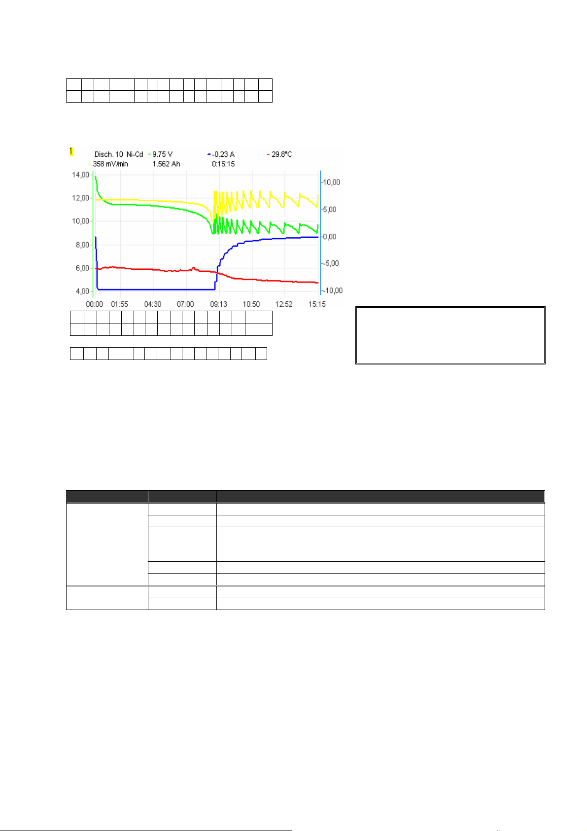
Discharging (0, 2 – 9, 9A, Revers, Auto)
D i s c h . 8 , 0 A R A
- - , - A h N i - C d 8
R - Reverse mode is on
A - Auto mode is on
Discharging lasts until battery voltage
reaches threshold voltage for given cell type.
In Auto mode current is decreased by ¼ each
time the threshold voltage is reached.
Discharging process ends when discharging
current is less than 200mA.
Reverse mode – energy from discharging
battery is transferred back to the supply
accumulator.
D 0 8 - 8 , 0 A 7 , 2 V ↓E
0 0 : 1 2 : 3 4 1 , 9 1 5 A h
every 5 seconds – second line
V b = 1 3 , 5 V 4 4 , 7 ° C
D 08 - discharging; 8 cells
-8,0A - actual, measured current
7,2V - actual, measured voltage
↓ - marker of decreasing voltage
E - marker of current limit (blinking)
00:12:34 - time elapsed from start of the process
1,915Ah - energy returned
Vb=13,5V - supply voltage
44,7°C - battery temperature
Disch. Keys Function
Battery
disconnected
Important Notices
• Maximal duration of this process – 14 hours.
• You must NOT use Reverse function if you are using external DC power supply unit.
• While working in reverse mode (reverse – on) discha rging current will be limited if voltage on supply battery
exceeds 15,3V (protection from overcharging)
+ or – change program
E current set up ( + , – ); E
E (1 s) remaining parameters set up
M (1 s) change work mode and cell type
M info window
E (1 s) stop discharging Battery connected
M LCD light
1. Revers On/Off – energy return ( + , – ); E
2. Auto On/Off – decreasing voltage ( + , – ); E
A bold ‘A’ after a value of current indicates
that charger has limited current due to
maximum power.
Charging Ni-Cd & Ni-MH (0,2 – 9,9A, Inflex, Reflex, Delta peak)
C h A r g e 8 , 0 A i r d
- - , - A h N i - C d 7
i - Inflex mode is ON
r - Reflex mode is ON
d - Delta – Δ low ( D – Δ high) function is ON
Charging ends when voltage drop (-Δv) or
inflex point is detected.
The Inflex mode allows finishing charging
process before unnecessary heating of
charged battery (inflex point marker –
vertical line on the current graph).
The Reflex mode makes it possible to
recharge batteries and avoid memory effect
(charging with short compensatory
discharging pulse)
C 0 8 8 , 0 A 1 2 , 9 V ↑ i
0 0 : 1 6 : 0 0 2 , 3 2 6 A h
every 5 seconds – second line
V b = 1 2 , 1 V 4 0 , 0 ° C
C 08 - charging; 8 cells
8,0A - actual, measured current
12,9V - actual, measured voltage
↑ - marker of increasing voltag e
i - marker of inflex point detection (blinking)
S - marker of slow start mode (blinking)
00:16:00 - time elapsed from start of the process
2,326Ah - energy taken
Vb=12,1V - supply voltage
40,0°C - battery temperature
Charge Keys Function
Battery
disconnected
Battery connected
Important Notices
• Maximal duration of this process – 14 hours.
• *) Forced start – charging diode protected battery (RC transmitter). Reflex function will be automatically
disabled! Charging currents > 1,2 A should
• Delta low – 7mV Ni-Cd, 3mV Ni-MH; Delta high - 10mV Ni-Cd, 5mV Ni-MH
• Delta high – rather for currents lower than 1C for Ni-Cd and 0,5C for Ni-MH
• Inflex – switched on for currents higher than 1C and from 4 cells
+ or – change program
E current set up ( + , – ); E
E (1 s) remaining parameters set up
M (1 s) change work mode and cell type
+ and – *forced start
M info window
E (1 s) stop charging
+ shorten slowly start (if pointer S blinks)
M LCD light
1. Inflex On/Off – stop at inflexion point ( + , – ); E
2. Reflex On/Off – equalizing impulse ( + , – ); E
3. Delta low / high – value -ΔV ( + , – ); E
not be used.
A bold ‘A’ after a value of current indicates
that charger has limited current due to
maximum power.
 Loading...