

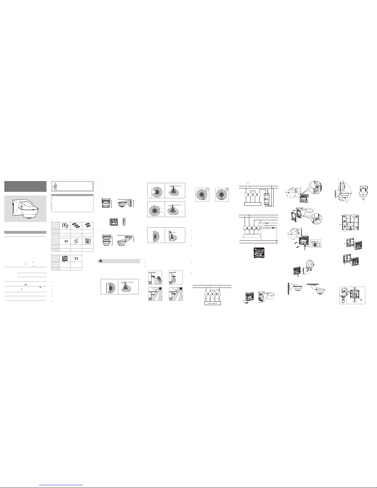
EL-produkter OS-300PA, OS-240PA, OS-360PA Instruction Manual
CAUTI ON!
A circuit br eaker (250VA C, 10A) type C according to
EN60898-1 o f load shall be installe d in the fixe d wiring for
protection .
Do not mount on conducti ve surface.
Do not open t he enclosur e frequentl y.
Turn off power wh en change th e light sour ces.
High in-rus h current wo uld be cause d when bulbs of certain
brands burn ed which mig ht damage th e unit perma nently.
1 PACKA GE CONT ENTS
Patte rn
Patte rn
Item
Item
Quant ity
Quant ity
1
3
Please disc onnect powe r completel y and read th e
entire inst ruction man ual careful ly before in stallation .
3 INS TALLATI ON AND WI RING
Top view
Side vi ew
FIG.1- A
2 PRODU CT DESCRIPT ION
2.1 Fea tures
3.1 Select a proper loc ation
Motio n
detec tor
Lens shi eld
(OS-36 0 / 300PA)
3.1.1 It is r ecommended to install t he detector at the heigh t of
2.5m. The d etection ra nge can reac h up to a radi us of
16m at the h eight of 2.5 m (See FIG.2-A & FIG.2-B).
Installati on and assem bly of elect rical equip ment
must be carr ied out by qu alified ele ctricians.
Contact a qu alified ele ctrician in the event of fault
or break dow n.
INS TRUCT ION MAN UAL
TECHNICAL SPECIFICATI ONS
220-2 40V~ 50 /60Hz
Rated Voltage
Load
3.1.2.3 Pay at tention to t he walking d irection in the test
proceedin g (See FIG.4) .
3.4 Install ation proced ure
This ou tdoor m otion d etect or can be i nstal led on wa ll dire ctly &
reces s corne r with mo untin g brack et or on th e ceili ng dire ctly or
on the Eu ropea n stand ard jun ction b ox.
FIG.9- A
Hook
Slot
When de tecto r is stan dby und er the au to mode , the
can be by passe d to turn t he ligh t(s) on f or 8 hour s by seri es
conne cting a p ower su pply sw itch.
detec tor
The ope ratio ns are as u nder me ntion ed :
When th e light i s off, tra nsfer t he powe r suppl y switc h from
“off → on → o ff → on” wit hin 2se c, afte rward s, ligh t will
chang e its sta tus fro m on 3sec & o ff 2sec & o n to conf irm tha t
has ent ered in to perm anent o n 8 hours m ode.detec tor
When th e light i s on, tra nsfer t he powe r suppl y switc h “off →
→ off → on” wi thin 2s ec, aft erwar ds, lig ht will t urn off f or
2sec, t hen tur ns on to co nfirm t hat det ector h as ente red int o
on 8 hour s mode.
on
perma nent
In the on 8 hour s mode, t he can be set to
mode by t ransf errin g the pow er supp ly swit ch “off → o n”
1sec, a fterw ards, l ight wi ll turn o ff for 2s ec. the n detec tor
enter s into au to mode a nd work w ith the k nob set tings .
perma nent detec tor
auto
withi n
3.3 Wi ring di agram s
3.3.1 N ormal o perat ion for l ighti ng cont rol (Se e FIG.5)
OUT DOOR P IR MOT ION DE TECTOR
for Li ghtin g or HVAC Au tomat ion Con trol
OS- / O S-30 0PA / OS-240PA 360PA
For lig hting ( with ju mper wi re)
Incan desce nt lamp : Max. 23 00W
AC Halog en lamp : M ax. 120 0W
LV Halog en lamp : M ax. 100 0VA /
600W (C onven tiona l)
Max. 90 0W (Ele ctron ic)
Fluor escen t lamp : Ma x. 1000 VA / 600W
(unco mpens ated)
Max. 90 0VA / 100µ F
(comp ensat ed)
LED lam p(Dri ver) : Ma x. 400W
Energ y Savin g : Max. 60 0VA / 400W
lamp (i nclud e CFL and P L lamp)
For HVAC ( remov e jumpe r wire)
Max.1 0A(co sφ=1) for 2 50VAC
Max.5 A for 30V DC
Max.3 A(cosφ= 0.4) fo r 250VAC
OS-30 0PA
Lux
Adjustment
Auto Off
Adjustmen t
Time
Operating
Temperature
o o
-20 C to +50 C
Environmen tal
Protection
IP55
Detection Ra nge
OS-360PA
360° , up t o 32m (R= 16m)
at heig ht of 2.5 m
Φ
300° , up t o R16m (f ronta l)/R1 4m(ba ckwar d)
at heig ht of 2.5 m
OS-24 0PA
240° , up t o R16m
at heig ht of 2.5 m
(fron tal)/ R8m(b ackwa rd)
Adjus table f rom app rox. 5s ec to 30m in
and Test &
Adjus table f rom app rox. 5Lu x to “
and “ ” (le arnin g range : 5Lux - 500 Lux)
& Holid ay
” (∞)
Can be used t o control li ghting or HVA C devices (v oltage free
contact).
Pulse count fu nction to a void the fal se triggeri ng problem
caused by en vironment.
Excepting t he provided Lux values, t he ambient l ight level c an
be read-in a s the Lux valu e for more fl exible appl ication.
Manual over ride for lig hting on 8hr s. is enable d by using an
external ro cker switch to control o r IR remote c ontrol.
Built-in 4 LE Ds provide War ning / Watch fu nction, whi ch
enables the detector to guarantee c omplete sur veillance o r
warning res pectively.
User friend ly design of un-falling mounting ba se and plug-i n
terminal bl ock for inst allation co nvenience.
OS-360PA
Φ32m
Φ14m
Φ10m
16m
O
360
2.2 Dim ensio n (See FI G.1-A & FI G.1-B & F IG.1- C)
Wall mount: 15 0 x 90 x 84mm
84mm
79mm
Φ90mm
80mm
FIG.3
3.1.2.1 The optimal loc ation for in stallation is at garden , corridor,
staircase , entrance, garage, pub lic lavator y, outdoor
parking ar ea, home and office, etc .
3.1.2.2 Sin ce the detec tor respond s to tempera ture change ,
please avo id the follo wing condit ions:
Avoid point ing the dete ctor toward the objects whose surfa ces
are highly r eflective, such as mirr or, glass, etc.
Avoid mount ing the dete ctor near he at sources, such as heat ing
vents, air c onditioner s, lights, e tc.
Avoid aimin g the detect or toward th e objects wh ich may be
swayed in th e wind, such as curtain, tall plants , etc.
3.1.2 Helpf ul tips for i nstallatio n
O
P
E
N
O
P
E
N
FIG.2- A
FIG.2- B
OS-240PA
OS-240PA / OS-300PA / OS-3 60PA
5
5
0
16m
16m
7
7
Top view
Side vi ew
O
240
FIG.5
FIG.13 -A FIG.13- B
3.4.1 .5
(See FI G.13-A ) to shor ten the d etect ion ran ge, or
O
turne d leftw ard and r ightw ard max . 90 h orizo ntall y
(See FI G.13-B ). Plea se adju st dete ctor he ad to get t he
desir ed dete ction f ield.
O
Detec tor hea d can be ad juste d downw ard max .40
FIG.11
FIG.12 -A FIG.12-B
Non-d roppi ng
screw
Botto m cover
Wall mou nt Ceili ng moun t
Rubber
gaske t
O
90
O90O
90
O
40
FIG.8
Ancho r
Wood Screw
Φ4x10mm
22
Wood Screw
Φ4x25.4mm
2
Jump or wir e
2
Lens shi eld
(OS-24 0PA)
3.4.2 C orner / r ecess m ount wi th moun ting br acket
3.4.2 .1 Ther e are cab le entr y knock- outs at b ack and b ottom
sides . Selec t the pro per hol es and br eak it th rough f or
wirin g. (See FI G.14- B & FIG.14 -C)
3.4.2 .2 Brea k the des ired sc rew kno ck-out s (See FI G.14- A). The n
fix the m ounti ng brac ket ont o reces s/con ner wit h wood
screw s (See FI G.15-A & FIG.15 -B), a nd fix bo ttom co ver
on moun ting br acket ( See FIG. 16). Re fer to FI G.5-F IG.7
to conn ect pow er cabl es, the n fix the d etect or head t o
the bot tom cov er and ad just th e detec tor hea d to be in
the cor rect po sitio n.
FIG.14 -A
FIG.14 -C
FIG.9- B
1
Corne r
mount ing
brack et
Patte rn
Item
Quant ity
Manua l
1
Rubber
washer
Screw s uppor t
Cable e ntry
knock- out
Cable e ntry
knock- out
3.4.1 Wall mou nt and ceili ng mount
3.4.1.1 Whe n installin g, the juncti on box of det ector can be stuck
on the bott om cover by i nserting th e hook into t he slot, so
that you do n’t need to hol d the produc t on hand, to make
installat ion conveni ently (See F IG.9-A & FIG.9- B & FIG.9-C) .
3.4.1.2 Ple ase strip of f 6-8mm of ca bles sheath ing by tool b efore
installat ion.
3.4.1.3 Feed t he electri c cables thr ough rubber gasket
(see FIG.8) and refer to illustrati on of FIG.5 - F IG.7 for
correct wi ring, then fi t the bottom cover on the wall or
ceiling fi rmly by two s crews (See F IG.10).
The unique h oliday mode for randoml y switching ON / OFF
load is work ed as a simpl e security f unction to p rotect your
property.
The IR remot e control is available f or quick and convenient
setting (fo r optional p urchase).
Acces sorie s for opt ional p urcha se
OS-240PA / OS-300PA / OS-360PA
3.2.3 Ho liday f unct ion
FIG.15-A
Corner installation
µ
FIG.1- B
Wall corner mounting bracket
(Optional purchase):80 74.5 28mmx x
74.5mm
80mm
28mm
5
5
0
16m
7
7
O
300
OS-300PA
Top view
Side vi ew
FIG.4
Less sens itive t o movem ent
directl y towar ds dete ctor
More sens itive t o movem ent
across th e detec tor
3.2.2 M anual o verri de for sw itchi ng ligh t on for 8 ho urs
(Lux is i ndepe ndent )
Under A uto mod e, the lo ad will t urn on au tomat icall y when th e
movem ent is de tecte d and the a mbien t light l evel is b elow th e
Lux sett ing val ue. Whe n no move ment is d etect ed and th e
delay t ime has e xpire d, the lo ad will t urn off a utoma tical ly.
3.2.1 A uto mod e
3.2 Fun ction
3.3.3 Fo r HVAC con trol (S ee FIG. 7)
M
Manual
Switch
A1
A2
Supply
Voltage
Fan
Heater
Contacto r
Blue
Brown
Red
Red
N
N
N1
L
L
L1
D1
D2
Motion d etect or
FIG.7
3
and adj ust the d etect or head t o be in the r ight po sitio n
(See FI G.12- A & FIG.12-B) .
.4.1. 4 Fix the de tecto r head to t he bott om cove r (See FI G.11)
FIG.10
6-8mm
FIG.14 -B
150mm
66mm
111mm
Φ90mm
80mm
Ceiling mount:
Ceiling mou nt: 166 x 90 x 111mm
FIG.1- C
166mm
1
2
3
5
4
6
7
8
Set the Lu x knob to “ Holid ay” po sitio n, LED wi ll flas h quick ly
for 10s ec, and t hen kee p on for 10 sec to in dicat e detec tor
enter ing int o Holid ay mode . Detec tor is un contr olled b y Lux and
Time und er Holi day mod e.
Under H olida y mode, t he ligh t will tu rn on aut omati cally
when th e ambie nt ligh t level i s below 5 0 Lux. The n the lig ht
will ra ndoml y turn ON a nd OFF be tween 1 0min to 1 hr for th e
next 4h rs. Whe n the loa d is off, LE D will fl ash by tu rns. Wh en
the loa d is on, th e 4 LEDs wi ll flas h simul taneo usly un der thi s
mode.
Exit Ho liday m ode: Du ring th e Holid ay mode , adjus t the
Lux knob t o other p ositi ons bes ide “Ho liday ”, loa d will
turn of f and LED w ill fla sh for 5s ec to ind icate d etect or exit ing
Holid ay mode .
1-8 hol es are
screw
knock u-out s
FIG.9- C
PASSIVE INFRA-RED SENSOR
FOR AUTOMATION CONTROL
OUTDOOR PIR MOTION DETECTOR
for Lighting or HVAC Automation
Control
OS-360PA OS-300PA OS-240PA
Wall mount:
1s.
Load
Stairca se time r
N
L
L
D1 D2
N
Motion d etect or
LN
OUT
IN
μ
3.3.2 Stair case timer s witch contr olled by one sensor (Time should
be set to (S ee FIG.6).
1S.
Blue
Brown
Red
Red
FIG.6
N
L
5
5
0
16m
16m
7
7
Top view
Side vi ew
O
180
Φ10m
Φ14m
Φ32m
Φ10m
Φ14m
Φ32m
Φ10m
Φ14m
Φ32m
Φ10m
Φ14m
Φ32m

4.4.1 Tes ter mus t be with in dete ction c overa ge.
4.4.2 S witch o n the pow er.
4.4.3 O S-240 PA / OS-3 00PA / OS- 360PA ta kes app rox.
60sec t o warm up w ith loa d and red L ED turn ing on,
then tu rns off a fter wa rming u p time.
4.4.4 Wa lk from o utsid e acros s to the de tecti on patt ern
until r ed LED an d load tu rn on for a pprox . 2sec, t hen tur n
off, the n ext tri gger sh ould be 2 sec int erval ( See FIG .19).
4.4.5 A djust d etect or head a iming t o the dir ectio n to be
detec ted (Se e FIG.13 -A & FIG.1 3-B) .
4.4.6 A djust M eter kn ob to rea ch desi red cov erage .
4.4.7 A djust Ti me knob t o chang e the swi tch off d elay ti me.
4.4.8 Re fer to po int "4. 5 Usage o f lens sh ield ", d etect ion
range a nd angl e can be ch anged b y using l ens shi eld .
4.4.9 Re peat th e steps 4 .4.4 to 4 .4.7 un til it me ets use r's
deman ds.
NOTE
Do not attem pt to open or repair the u nit without qualified
electricia n while it is malfunctio ned.
The followi ng conditio ns may cause lower sensi tivity:
In very fog gy days, the sensitivit y may be less due to
moisture c ollecting o n the lens.
In very hot days, the se nsitivity m ay be less si nce high
ambient te mperature i s close to bo dy temperat ure.
In very col d days when h eavy clothi ng is dresse d, especial ly
the facial area is cove red, very li ttle heat wi ll be emitte d
from the bo dy causing t he unit to be less sensit ivity.
Cleaning: Wipe with dry cloth only. Soa p or rough cl oth
may damage the detecto r lens.
Walk tes t proce dure
Maint enanc e and Rep air
Avoid aimin g the detect or
towards any heat source s,
such as air c onditionin gs,
electric fa ns, heaters or any
highly refl ective surf aces.
Make sure th ere are no
swaying obj ects within the
detection c overage.
There are he at
sources, hi ghly
reflective objects or
any objects which
may be swaye d in
the wind wit hin the
detection c overage.
Nuisance
triggered
1. Set auto o ff time to a
shorter ti me and check if
the load is switched of f or
not accord ing to the pr e set off tim e.
2. Keep away f rom detecti on
coverage t o avoid acti vat ing detect or while doi ng
the test.
3. Refer to wi ring diagra ms
for correc t connectio n.
When OS- normally,
check assum ptive probl ems and sugg ested solut ions in foll owing
table that w ill hopeful ly solve you r problem.
OS-240PA / OS -300PA / 360PA work s ab
1. Auto off t ime is
set too lon g.
2. Detector is
nuisance
triggered .
3. Wired inco rrectly.
Lighting
device
does not
turn on
Lighting
device
does not
turn off
1. Power does n ot
turn on.
2. Wired inco rrectly.
3. Lux knob ad justed
incorrect ly.
4. Malfunct ioned
load.
1. Switch on the power.
2. Refer to wi ring diagra ms
for correc t connectio n.
3. Check if Lu x knob is set to
the correc t position.
4. Replace th e disabled l oad
with a new o ne.
5 TROUBL E SHOOTING
Problem Possible ca use
Suggested S olution
4.3 LED w atch fu nctio n
Load 2se c
on, 2se c
off for
indic ation
Test
mode
W
W
W
2sec
2sec
LED
does no t
turn on
1. Exceed ing the
detec tion
range .
2. No power
suppl ied.
3. Wired
incor rectl y.
1. Walk in t he effe ctive
detec tion ra nge
2. Swit ch on the p ower.
3. Refer t o wirin g diagr ams.
for cor rect co nnect ion.
Load ON.
Not Test
mode
Load OFF.
W
W
Load ON.
Load OFF.
W
W
4.3.1 W hen the w atch kn ob is set t o eithe r “ON” or “OF F”an d
is set to “Test ”, once t he dete ctor de tects
o nly one L ED of the 4 pcs bui lt-in r ed LEDs w ill
2sec. the n turn of f. If the d etect or dete cts
continu ously, t he red LE D will tu rn on for 2 sec
2sec r epeat edly wh ich is un contr olled b y Lux
no move ment is d etect ed.
Time kno b
movem ent,
turn on f or
movem ent .
and tur n off .
setti ng unti l
NOTE
When the actual light level is out of the range 5 - 500Lux,
detector will learn 25sec, then the red LED flashes quickly for 5sec.
When the actual light level is below 5Lux, Lux value is set to 5Lux,
or is above 500Lux, Lux value is set to (uncontrolled by ∞ Lux
setting). Installer should be away from the detector to avoid
affecting the luminous flux that reaches the detector when learning
Lux value.
3.28.02 00003 60040 0
Copyrig ht 2013 A urex In dustr ies, In c.
All right s reser ved. No r eprod uctio n, copy, o r trans missi on of thi s produ ct
may be made w ithou t writi ng perm issio n.
C
The pur pose of w alk tes t is to sel ect a pro per loc ation
and gai n the des ired de tecti on cove rage. P lease s et Time kn ob
to "Test" a nd Mete r knob to " +", the n refer t o the fol lowin g
steps c onduc ting a wa lk test .
It take s appro x. 60se c for det ector t o warm up a fter po wer is
suppl ied, th en it ent ers int o norma l opera tion mo de to car ry
out a wal k test.
FIG.19
Time
Watch
Watch
This mo tion de tecto r can use l ens shi elds fo r maski ng the
undes ired de tecti on area . Each le ns shie ld has 2 la yers
(laye r A / layer B ), each l ayer in clude s 13 smal l segme nts and
o
each sm all seg ment ca n cover 8 .5 det ectio n angle .
For exam ple to in stall t he dete ctor at t he heig ht of 2.5 m, the
detec tion ra nge is a di amete r of appr ox. 10m ( look do wn lens ) if
the com plete l ens shi elds ha ve been u sed, an d up to 14m
diame ter if on ly the la yer A of le ns shie ld has be en used , and up
to 32m di amete r if no len s shiel d has bee n used. ( See FIG. 20-A
& FIG.20 -B)
FIG.18-C
W
LED and load off
Detect or swit ches to A UTO mode
Watch
Watch
Φ10m
The whole le ns shield is used.
A
B
Layer A of the lens shield is used.
4x8.5
o
2.5m
2.5m
LED and load keep on 5sec
(the actual light level range
is 5 - 500Lux)
500Lux)
LED flashes quickly for 5sec &
Load is off (the actual light
level range is out of 5 -
W
W
LED flashes slowly for 25sec
& load is off
W
4.4 Wal k test( Lux set ting is i nvali d)
NOTE
4.5 Usa ge of len s shiel d
OS-240PA has 2pcs lens shields.
OS-300PA has 3pcs lens shields.
OS-360PA has 3pcs lens shields.
NOTE
4x8.5
o
Φ14m
Φ32m
Φ10m
Part of the len s shield is u sed.
FIG.20 -B
2.5m
4.5.1 Fixing lens shield: Take off the decorative frame of the detector
head and insert the lens shield into the slot of decorative frame
as following illustration (See FIG.21 & FIG.22). Then put the
decorative frame back to the right position of the detector head.
The shadow part of the lens shields in the FIG.20-A & FIG.20-B are
referring to the cutoff parts.
FIG.22
FIG.21
The sec ond
LED 2se c on,
2sec of f for
indic ation
Φ14m
4.3.3 S et the Wat ch knob t o OFF pos ition , the LED w atch
funct ion is di sable d and the 4 pcs bui lt-in re d LEDs ke ep
off, excepti ng the Ti me knob i s set to “Tes t” pos ition
which t he LED wi ll func tion as d escri bed in 4. 3.1 und er
this co nditi on.
be
Φ10m
2.5m
Φ14m
Part of the len s shield is u sed.
4.3.2 S et Watch k nob to “ON ” and Tim e knob to t he othe r
posit ion the L ED watc h funct ion is
the 4pc s built- in red LE Ds will w ork
Howev er, the afo resai d watch
out onl y when Tim e knob is n ot set to
activ ated. I n this mo de,
as desc ribed i n below
table . funct ion is ca rried
“Test”, p lease n ote.
Time
setti ng
Watch
mode
React ion of LED and Lo ad
Detec tor is
stand by
LEDs do n ot
actio n
Lux
contr ol
Uncontrolled
by Lux.
Time
setti ng
Watch
mode
React ion of LED and load
LEDs fl ash
by turn s.
LEDs no a ction
4pcs LE Ds
are fla shing
quick ly for
5sec.
Lux
contr ol
Controlled
by Lux.
LEDs no action
Detec tor is
trigg ered
Load OFF
Detec tor:
stand by
Load: OFF
Detec tor: to
be trigge red
Load: ON
FIG.20 -A
Time
15m
5m
30m
5s
Test
1s
15m
5m
30m
5s
Test
1s
ON
OFF
ON
OFF
ON
OFF
ON
OFF
4.2 Lux l earni ng func tion wi th knob
Learn ing pro cedur e:
4.2.1 Ad just the kn ob to “ ” when the amb ient li ght leve l
matche s with the des ired va lue (See FI G.18-A ).
4.2.2 Wh en the knob is s et to “ ” origina lly, it shou ld be adju sted
to other pos ition mo re than 1s ec, then go es back to “ ”
(See FIG. 18-B) .
4.2.3 Th en the load tu rns off. LE D starts t o flash slo wly indi catin g
enteri ng into lea rning mo de, the du ratio n is 25sec.
Afterw ards, th e LED and the lo ad will kee p on 5sec or LED
flashe s quickl y for 5sec an d load turn s off to conf irm
succes sful lea rning (S ee FIG.1 8-C).
4.2.4 Af ter lear ning pro cedur e, the det ector re turns to AU TO
mode with LE D and load be ing off.
Adjust knob to
“ ” from
other position
Adjust knob to
other position
from ” “
1sec after, goes
back to ” “
FIG.18-A
FIG.18-B
4.1 Tim e, Mete r, Lux, Wat ch knob
Knob Functio n
Knob settin g
Set del ay
off tim e
of load
Range: Adjus table from a pprox.
5sec to 30m in
Test : Test mode (Load a nd red
LED will be 2sec on, 2se c
off)
: Short imp ulse mode fo r
staircase timer switc h
control (Lo ad will be 1s ec
on, 9sec of f)
Set the l ight
value f or
switc hing
on load
and hol iday
funct ion
Meter
Set the
detection
range
4 OPERATI ON AND FUNCT ION
Range: A djust able fr om
“-” (r= 3m) to “+ ”
(r=16 m)
appro x.
Set LED
alert
funct ion
ON: Acti vate LE D fu nctio n.
OFF: Dea ctiva te LED
funct ion
alert
alert
Lux
Time
Watch
Range : approx.
5Lux to “ ”(∞).
Adjustable from
(lear n): The a ctual a mbien t
light l evel (5 - 500 Lux)
can be re ad in.
Holid ay: The l oad wil l rando mly
turn on /off fo r the tim e
of 10mi n to 1hr. in 4h rs.
ON
OFF
1s
5
100
500
15m
5m
30m
5s
Test
1s
Holiday
5
100
500
Holiday
5
100
500
Holiday
5
100
500
Holiday
5
100
500
Holiday
5
100
500
Holiday
The microwave sensor is unaffected by the lens shield.
Rubber w asher
FIG.16
3.4.3 Wa ll / ceil ing mou nt with E urope an stan dard ju nctio n
box
3.4.3 .1 Pull ou t AC powe r cable s from Eu ropea n stand ard
junct ion box ( See FIG. 17-A) t hen str ip off 6- 8mm of
cable s heath ing for w iring.
3.4.3 .3 Fix the d etect or head t o the bot tom cov er (See F IG.10 )
and adj ust the d etect or head t o be in the c orrec t posit ion.
FIG.17 -B
6-8mm
35 - 40mm
FIG.17 -A
Recess installation
FIG.15-B
3.4.3 .2 Feed th e elect ric cab les thr ough ru bber ga sket (S ee
FIG.8) a nd refe r to FIG. 5 - F IG.7 for c orrec t wirin g.
Then fi t the bot tom cov er on the E urope an stan dard
junct ion box f irmly b y two scr ews (Se e FIG.10 - F IG.17 -B).
 Loading...