

ELPRO Video Labs s.r.l.
Via della Praia 4/a FERRIERA di BUTTIGLIERA ALTA (TO) – ITALY
Tel.+39 0119348778 - FAX +39 0119348779
TPA110series CAT5/6 VIDEO, AUDIO & IR TRANSCEIVERS
1
TPA110-M 09/06/08
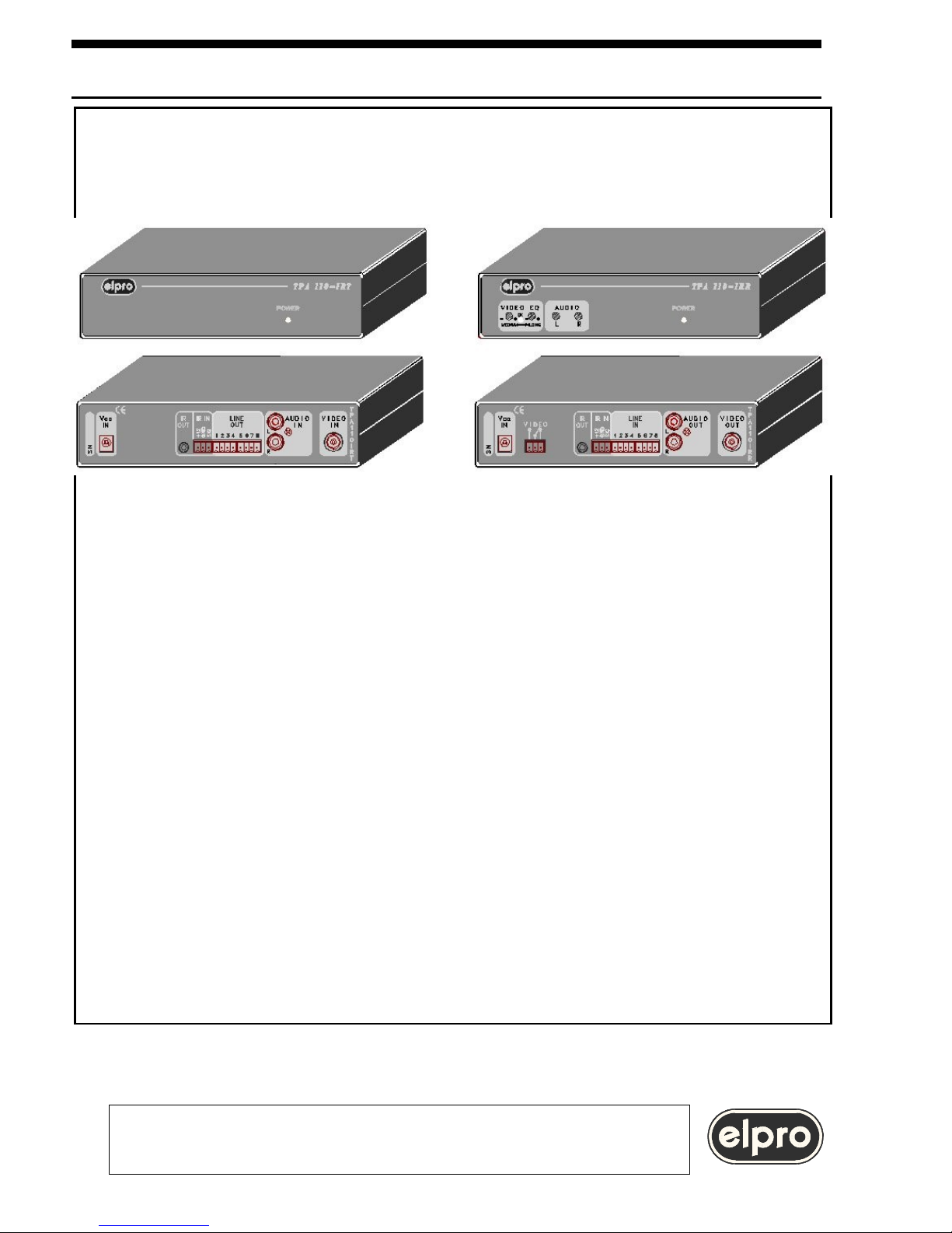
Video and audio stereo Transmitter / Receiver
Compensation adjustment
Video signal in arrival indication
Dry contact for video present
Bi-directional IR transmission
Carrier frequency up to 1.2MHz
Compatibile 19"

INDEX
1.0 Overview
2.0 Power supply
3.0 Settings
4.0 Installation
5.0 Video and audio signal equalization
6.0 Accessories
7.0 Technical data
8.0 Notes
When installing the unit, please read this handbook carefully.
The manufacturer shall not be held responsible for any damage or injury caused
by use, even correct, of its products.
The data and characteristics of the product may be modified without prior notice
8.0 NOTES
232
TPA110series CAT5/6 VIDEO, AUDIO & IR TRANSCEIVERS
INSTALLATION AND USE OF THE TPA110 SERIES
TPA110
ELPRO Video Labs s.r.l.
Via della Praia 4/a FERRIERA di BUTTIGLIERA ALTA (TO) – ITALY
Tel.+39 0119348778 - FAX +39 0119348779
1.0 OVERVIEW
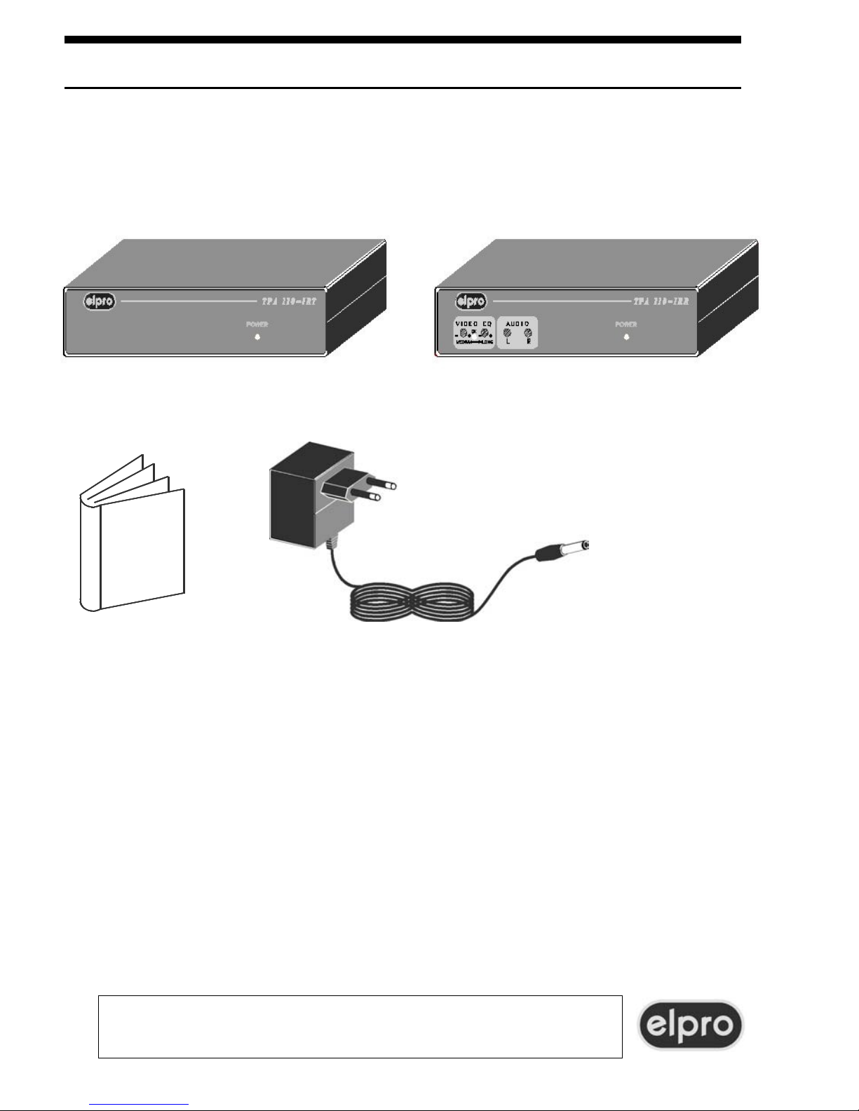
Thank you for buying this product. Check the contents of the packaging carefully.
It contains:
322
TPA110series CAT5/6 VIDEO, AUDIO & IR TRANSCEIVERS
ELPRO Video Labs s.r.l.
Via della Praia 4/a FERRIERA di BUTTIGLIERA ALTA (TO) – ITALY
Tel.+39 0119348778 - FAX +39 0119348779
- The kit for fastening to a 19" structure (If ordered separately)
− The TPA110 T/R dual transmitter/receiver or TPA110 IRT / IRR
− N°2 mains adapter
code ADM001
− This
handbook
If you have purchased the TPA110 IRT / IRR model, this also permits passing of
an IR (infrared) signal and will provide you with visual indication of the correct
incoming video signal.
Also, a dry contact (VIDEO) indicates that the correct incoming video signal is
present. This can be useful for remote monitoring of the condition of the incoming
video signal (present or alarm).
Transmission of the IR signal permits remote control using an IR remote control
from one environment of a unit located in another environment .
To do this, an external IR receiver will be connected to the TPA110 IRR and an IR
emitter to the TPA110 IRT or vice versa.
This permits bi-directional but not simultaneous IR transmission.
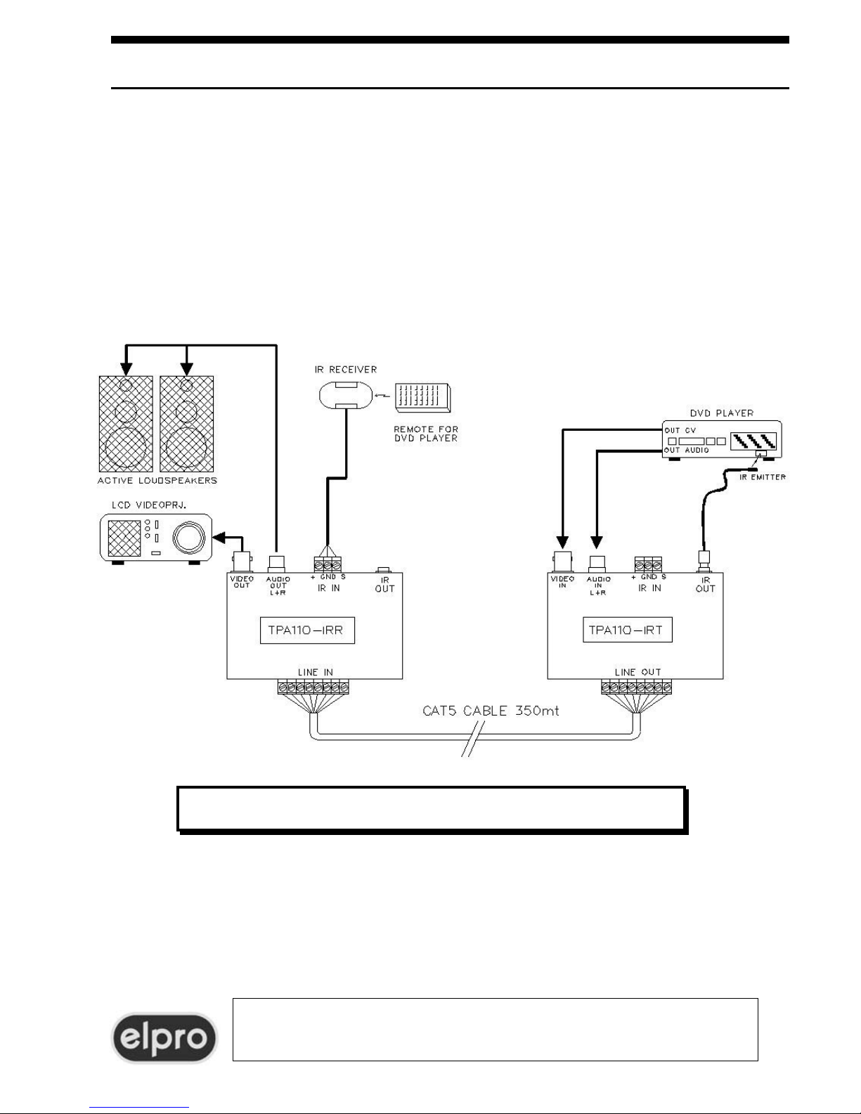
To do this, you need:
-an amplified external IR receiver normally installed on a wall and connected to
the IR IN terminals of the TPA110 IRT or TPA110 IRR;
-an IR emitter which will be connected to the IR OUT jack of the TPA110 IRR or
TPA110 IRT.
The IR emitter will be positioned on the front of the appliance to be controlled
(DVD player, Satellite etc.).
For other information regarding connection of IR devices, refer to paragraph 4.5
Line OUT
IR IN
IR OUT
Line IN
Audio out
Distortion
IR IN
IR OUT
214
TPA110series CAT5/6 VIDEO, AUDIO & IR TRANSCEIVERS
ELPRO Video Labs s.r.l.
Via della Praia 4/a FERRIERA di BUTTIGLIERA ALTA (TO) – ITALY
Tel.+39 0119348778 - FAX +39 0119348779
TPA110-IRT/TPA110-IRR TYPICAL SYSTEM
2.0 POWER SUPPLY
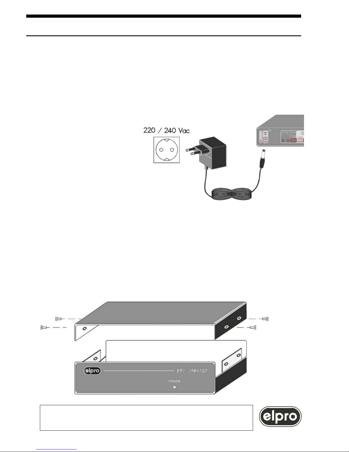
The dual TPA110 is powered only via the AC/AC adapter code ADM001 provided.
WARNING
Use of any other adapter could damage the appliance.
Any operations must be carried out by qualified personnel.
The adapter must be inserted
in a 230 Vac/50Hz outlet.
3.0 SETTINGS
The dual TPA110 T/R has no internal settings.
There are two jumpers inside the dual TPA110 IRT / IRR to adapt use of this to
various IR receivers.
The cover must be removed to set the jumpers. Remove the top four screws to the
sides of each unit.
TPA110series CAT5/6 VIDEO, AUDIO & IR TRANSCEIVERS
ELPRO Video Labs s.r.l.
Via della Praia 4/a FERRIERA di BUTTIGLIERA ALTA (TO) – ITALY
Tel.+39 0119348778 - FAX +39 0119348779
5

The jumpers are identified as W1 and W2
W1: TTL : IR receiver with TTL output
ANALOG : IR receiver with analog output
W2: LoZ (Low impedance): : IR receiver with power output
HiZ (High impedance) : IR receiver with high impedance output
The most frequent cases are as follows
-IR receiver with power output : position W1= ANALOG; W2= LoZ
-IR receiver with TTL output : position W1= TTL; W2= HiZ
The factory setting is as follows:
W1: ANALOG
W2: LoZ
TPA110series CAT5/6 VIDEO, AUDIO & IR TRANSCEIVERS
ELPRO Video Labs s.r.l.
Via della Praia 4/a FERRIERA di BUTTIGLIERA ALTA (TO) – ITALY
Tel.+39 0119348778 - FAX +39 0119348779
TPA110
6
19
TPA 110 IRT
TPA 110 IRR

4.0 INSTALLATION
In a typical installation, there are usually 2 independent video sources to be
directed towards two destinations. A CAT5 cable is used for transmission between
the transmission and receiving units. The CAT5 cable is the standard cable used
for local computer networks and consists of four unshielded twisted pairs (UTP).
The maximum lengths of the CAT5 cable that can be compensated are:
-375mt. for cable type AWG26
-500mt. for cable type AWG24
-650mt. for cable type AWG22
For monitoring and signal present type applications, sections of up to 900mt of
AWG22 CAT5 cable can be used.
In critical noise conditions, in order it improve the all-round performance of the
system, the CAT6 cable can be used.
WARNING
Pay particular attention to grounding
of the sources and destinations (see par. 4.2)
4.1 Connection of the CAT5 cable
TPA110series CAT5/6 VIDEO, AUDIO & IR TRANSCEIVERS
ELPRO Video Labs s.r.l.
Via della Praia 4/a FERRIERA di BUTTIGLIERA ALTA (TO) – ITALY
Tel.+39 0119348778 - FAX +39 0119348779

5.2 Go to the TPA110 R/IRR receiver unit and connect a waveform monitor or an
oscilloscope that can be synchronized on the horizontal synchronism (H) to the output
video signal, making sure that the input of the instrument is terminated at 75Ω.
If the section of CAT5 cable is equal to or less than 50% of the maximum section
that can be compensated (see above):
5.3 Set the LONG trimmer to zero (fully counterclockwise)
5.4 Adjust the MEDIUM trimmer on the front panel of the TPA110 R / IRR receiver
unit until the amplitude of the burst on the pedestal is between 210 and 300mVpp
(If necessary, adjust the LONG trimmer turning this a few degrees in a clockwise
direction).
5.5 Check that the amplitude of the negative synchronism is between 250 and
300mV
178
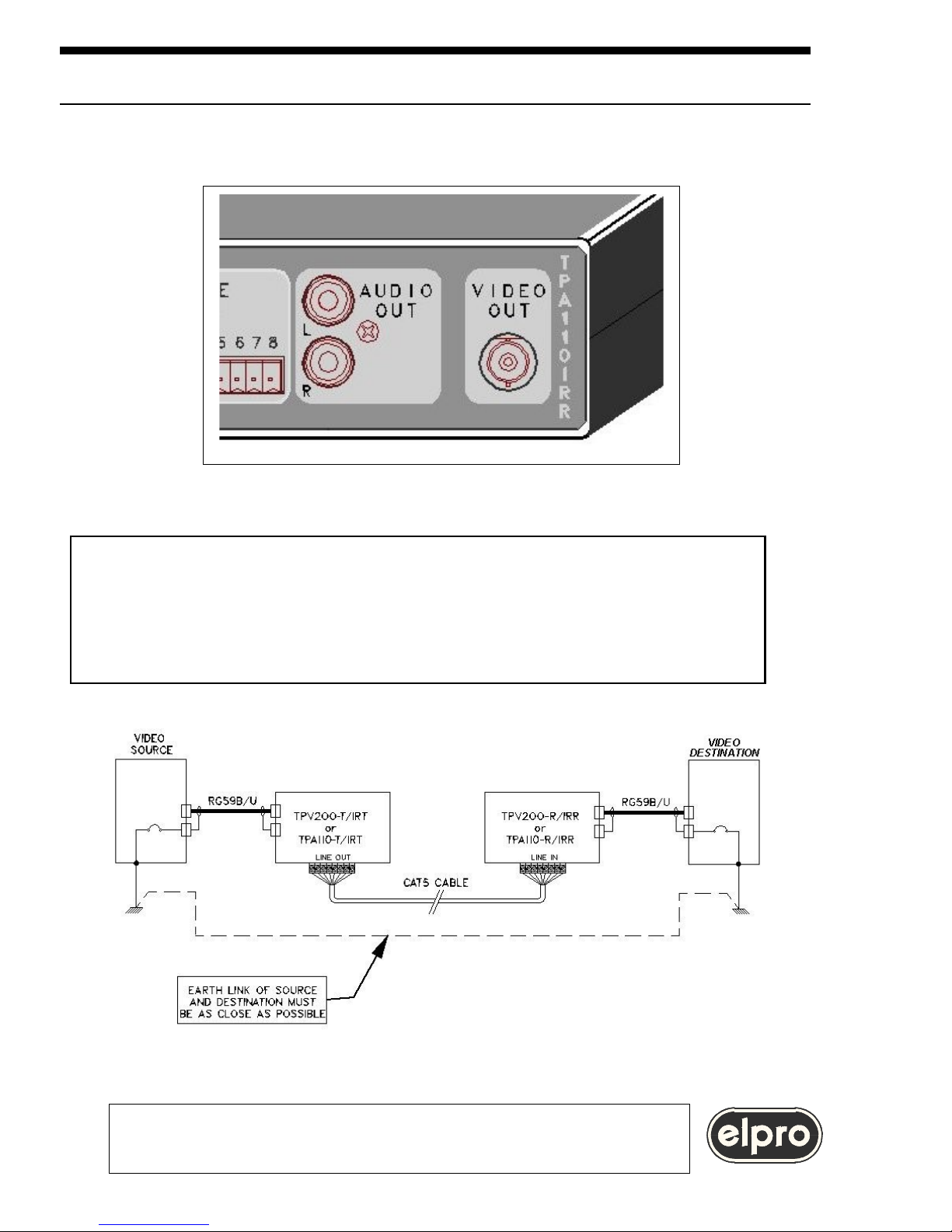
The video destination must be connected to the BNC VIDEO OUT connector of
the TPA110 R / IRR receiving unit.
ELPRO Video Labs s.r.l.
Via della Praia 4/a FERRIERA di BUTTIGLIERA ALTA (TO) – ITALY
Tel.+39 0119348778 - FAX +39 0119348779
TPA110series CAT5/6 VIDEO, AUDIO & IR TRANSCEIVERS
916
WARNING
For optimal system functioning the ground connections
of the sources and of the destinations
must be as equipotential as possible.
Different ground potentials may cause faults.

4.3 Connection of the VIDEO dry contact
The VIDEO dry contact belongs to a relay that is energized when a correct video
signal is received. This contact can be used for remote monitoring of the
presence of the incoming video signal or to indicate an alarm if the video signal is
missing.
4.4 connection of AUDIO signals
The stereo audio source must be connected to the RCA connectors called AUDIO
IN L and R present on the TPA110 T / IRT.
The video destination must
connected to the RCA connectors
called AUDIO OUT L and R
present on the TPA110 R / IRR.
WARNING
The maximum permitted audio signal is +10dBm.
10 15
TPA110series CAT5/6 VIDEO, AUDIO & IR TRANSCEIVERS
ELPRO Video Labs s.r.l.
Via della Praia 4/a FERRIERA di BUTTIGLIERA ALTA (TO) – ITALY
Tel.+39 0119348778 - FAX +39 0119348779

4.5 IR (Infrared) SIGNAL connection
Usually, IR transmission is used to control an appliance (DVD player, Satellite,
etc.) located close to the transmitting unit, from the receiving station using a
remote control.
However, the circuitry used in the dual TPA110 IRT/ IRR also permits a reverse
path. Transmission may therefore be bi-directional but not simultaneous.
WARNING
If two users transmit an IR signal concurrently from the receiving and
transmitting station, a line conflict occurs and the transmissions will fail.
4.5.1 IR RECEIVER connection
The IR receiver is an electronic device able to transform IR light impulses emitted
by a remote control into an electrical signal.
The IR receiver must be positioned so that can be easily reached by the IR beam
emitted by the remote control. It is usually installed on a wall at medium-high
height. When installing the IR receiver, always comply with the manufacturer's
instructions regarding:
-Sensitivity
-Exposure to environmental and sunlight
-Settings and calibration
WARNING
Amplified IR receivers must be used
When selecting the IR receiver, the user must pay particular attention to the
operating frequency of the remote control whose signal is remotized.
Most remote controls operate at low frequencies but some manufacturers (Bang &
Olufsen, Kenwood, Pioneer) use remote controls with carrier frequencies of up to
1,125MHz.
WARNING
Make sure that you buy an IR receiver
that is compatible with the frequency of the remote control.
The TPA110 IRT / IRR are compatible with
frequencies of up to 1.2MHz
TPA110series CAT5/6 VIDEO, AUDIO & IR TRANSCEIVERS
ELPRO Video Labs s.r.l.
Via della Praia 4/a FERRIERA di BUTTIGLIERA ALTA (TO) – ITALY
Tel.+39 0119348778 - FAX +39 0119348779

The IR receivers available on the market are of the 3-wire type: Positive (+), GND
(0 Volt) and SIGNAL.
Connect the IR receiver to the
terminals of the TPA110 IRR / IRT
unit marked IR IN +12, GND and
SIG. If the cable leading out of the
receiver is fitted with a 3.5 mm
stereo jack, cut the cable and identify
the three wires to be connected to IR
IN +12, GND and SIG terminals of
the TPA110 IRR / IRT.
For identification of the pin-out of
the receiver, refer to its user
manual.
Most of the receivers on the market
have a power SIGNAL output, i.e.
able to drive an IR transmitter IR
directly. In this case, no setting is
required on the TPA110 unit as it is
factory set for this type of interface.
If the IR receiver has a SIGNAL output at TTL level, the TPA110 IRR / IRT unit
must be set as described in paragraph 3.0
WARNING
If available, use of IR receivers with TTL output
can be recommended as they consume less and cost less
4.3.2 Connection of the IR (Infrared) EMITTER
The IR emitter is an optical device able to transform en electrical signal into a
beam of IR light.
The IR emitter usually consists of a plastic capsule with a cable leading out of this
terminated with a 3.5 mm mono jack.
The capsule in which the infrared light emitter led is embedded must be
positioned, using transparent adhesive tape, on the front of the appliance to be
controlled.
12 13
TPA110series CAT5/6 VIDEO, AUDIO & IR TRANSCEIVERS
ELPRO Video Labs s.r.l.
Via della Praia 4/a FERRIERA di BUTTIGLIERA ALTA (TO) – ITALY
Tel.+39 0119348778 - FAX +39 0119348779
IR REMOTE
CONTROL

Connect the 3.5 mm mono jack leading out of the IR emitter capsule in the jack of
the TPA110 IRT / IRR unit identified as IR OUT.
WARNING
The jack of the IR emitter must have the following connections:
Tip : (A) Anode Emitting led
Sleeve : (K) Cathode emitting led
Inside the TPA110 IRT / IRR the sleeve is connected to ground (GND)
13
TPA110series CAT5/6 VIDEO, AUDIO & IR TRANSCEIVERS
ELPRO Video Labs s.r.l.
Via della Praia 4/a FERRIERA di BUTTIGLIERA ALTA (TO) – ITALY
Tel.+39 0119348778 - FAX +39 0119348779
IR EMITTER PIN-OUT
Jack mono 3,5mm

WARNING
Use of dual IR emitters is permitted to control up to 2 appliances.
4.5.3 Receivers with down Converter
Certain IR receivers (Xantech) compatible with frequencies of 455KHz and
1.125MHz convert the carrier frequency down to 40KHz.
In this case, you must also buy the modulator with related power supply which
reconverts the 40KHz up again.
The IR emitter must be connected to the output of the modulator while the IR OUT
output of the TPA110 IRT / IRR must be connected to the input of the modulator.
remote control.
-Sensitivity
1,125MHz.
14 11
TPA110series CAT5/6 VIDEO, AUDIO & IR TRANSCEIVERS TPA110
ELPRO Video Labs s.r.l.
Via della Praia 4/a FERRIERA di BUTTIGLIERA ALTA (TO) – ITALY
Tel.+39 0119348778 - FAX +39 0119348779
USE OF DUAL IR EMITTER

This level is compatible with the std, outputs of CD,
DVD players and VHS available on the market.
TPA110series CAT5/6 VIDEO, AUDIO & IR TRANSCEIVERS
ELPRO Video Labs s.r.l.
Via della Praia 4/a FERRIERA di BUTTIGLIERA ALTA (TO) – ITALY
Tel.+39 0119348778 - FAX +39 0119348779

5.0 VIDEO AND AUDIO SIGNAL EQUALIZATION
The CAT5 cable introduces considerable losses on the signal in transit.
A 100-meter long AWG26 CAT5 cable attenuates 50% of the color components
of the video signal. As the composite video signal is a complex signal that does
not accept downgrading, for each installation calibration must be performed in
order to offset cable losses. The unit that makes this compensation is the
receiving unit, in our case the TPA110 R / IRR.
WARNING
The TP110R / IRR unit is precompensated for 50 mt of CAT5 cable
However, use of a cable with a length of less than 50mt
does not affect system functioning.
The maximum lengths of the CAT5 cable that can be compensated are:
-375mt. for cable type AWG26
-500mt. for cable type AWG24
-650mt. for cable type AWG22
For monitoring and signal present type applications, sections of up to 900mt of
AWG22 CAT5 cable can be used.
In critical noise conditions, in order it improve the all-round performance of the
system, the CAT6 cable can be used.
The CAT6 cable has the same characteristics as the CAT 5 but features
improved insulation between the internal pairs.
Losses are compensated using the VIDEO EQ MEDIUM LONG trimmers.
Where MEDIUM and LONG refer to the length of the CAT5 cable.
The MEDIUM trimmer is used to compensate sections of cable up to half the
maximum length indicated above. For compensation of longer cable sections,
the MEDIUM trimmer is set to maximum (completely clockwise) and the LONG
trimmer is adjusted.
To calibrate the system, proceed as follows, separately for the 2 video signals:
5.1 Using a generator, send a standard video signal, for example the bars at
75% or CCIR17 line, to the input of the TPA110 T / IRT transmitter unit.
TPA110series CAT5/6 VIDEO, AUDIO & IR TRANSCEIVERS
ELPRO Video Labs s.r.l.
Via della Praia 4/a FERRIERA di BUTTIGLIERA ALTA (TO) – ITALY
Tel.+39 0119348778 - FAX +39 0119348779
916

178

If the section of CAT5 cable exceeds 50% of the maximum section that can be
compensated (see above):
5.3 Turn the MEDIUM trimmer to maximum (completely clockwise).
5.4 Adjust the LONG trimmer on the front panel of the TPA110 R / IRR receiver
unit until the amplitude of the burst on the pedestal is between 210 and 300mVpp
5.5 Check that the amplitude of the negative synchronism is between 250 and
300mV
WARNING
The trimmers are factory set for minimum
compensation (counterclockwise)
of 50 mt. of AWG26 CAT5 cable.
If you have purchased the dual TPA110 IRT / IRR, arrival of a correct video
signal is indicated by lighting up of the green led located between the two
adjustment trimmers. if the green led is off, this means that there is no correct
video signal on the output.
4.0 INSTALLATION
system, the CAT6
18 7
TPA110series CAT5/6 VIDEO, AUDIO & IR TRANSCEIVERS TPA110
ELPRO Video Labs s.r.l.
Via della Praia 4/a FERRIERA di BUTTIGLIERA ALTA (TO) – ITALY
Tel.+39 0119348778 - FAX +39 0119348779
ELPRO Video Labs s.r.l.
Sync =
250÷300mV
Burst =
210÷300mV
LED PRESENZA VIDEO
Audio LEVEL trimmers

Presence of the incoming video signal is also indicated by a relais whom contacts
are available to the terminals VIDEO.
Drawing represents the released contacs.
For other information regarding connection, refer to paragraph 4.3
For the stereo audio signal, losses due to the cable are not so significant as for
the video signal.
However, for long sections of cable, the output level of the audio signal must be
calibrated in order to compensate for losses due to the cable.
To do this, turn the LEVEL L and R trimmers in a clockwise direction until the
audio signal level reaches that desired.
ELPRO Video Labs s.r.l.
Via della Praia 4/a FERRIERA di BUTTIGLIERA ALTA (TO) – ITALY
Tel.+39 0119348778 - FAX +39 0119348779
TPA110series CAT5/6 VIDEO, AUDIO & IR TRANSCEIVERS

6.0 ACCESSORIES
The unit is supplied complete with:
- The mains adapter code ADM001
The following are available on request:
-A kit of accessories for fastening of units to a 19" rack.
Fastening is possible with a single unit using the tabs code 01069014, or with a
second, mechanically compatible Elpro unit to the side.
Assembly of the accessories for assembly in a 19" rack is shown in the drawing.
TPA110series CAT5/6 VIDEO, AUDIO & IR TRANSCEIVERS TPA110
ELPRO Video Labs s.r.l.
Via della Praia 4/a FERRIERA di BUTTIGLIERA ALTA (TO) – ITALY
Tel.+39 0119348778 - FAX +39 0119348779
20 5

7.0 TECHNICAL DATA
TPA110T / TPA110 IRT:
Video Input type :BNC, AC coupled
Input ret.loss :35 dB at 5 MHz
Audio input type :RCA socket, AC coupled
Input impedance :20KΩ
Input level :+10dBm max
Line OUT :8 Phoenix screwtype detachable (four pairs balanced)
IR IN :3 Phoenix screwtype detachable
IR OUT :jack mono 3.5 mm
IR Signal type :Carrier frequency up to 1.2MHz
TPA110R / TPA110 IRR:
Line IN :8 Phoenix screwtype detachable (four pairs balanced)
Video OUT :BNC, not clamped
Equalization/Frequency response
from 30KHz to 5 MHz :±1,5 dB up to 375 mt CAT5 AWG26 cable;
:±1,5 dB up to 500 mt CAT5 AWG24 cable;
:±1,5 dB up to 650 mt CAT5 AWG22 cable;
Delay :2.0 µs at 375mt CAT5 cable
Differential gain :0.6 % worst case
Differential phase :1.2° worst case
LF Response :1.2 % on 50Hz squarewave
Hum & noise :-70 dBm unweighted with 375 mt CAT5 AWG26 cable
VIDEO (Video presence) : 3 Phoenix screwtype detachable C, NO, NC, dry contact
Audio out :RCA socket
Output level :Adjustable for up to 375 mt CAT5 AWG26 cable
Max. output level :+10dBm
Output impedance :150Ω
Audio response :-0.5 dB from 10Hz to 20KHz; -3 dB at 95 KHz
Distortion :0.04% from 20Hz to 20KHz at +6dBm
Crosstalk L/R (Worst case) :55 dB at 16KHz worst case
Hum & Noise :-64 dBm unweighted through 350mt CAT5 cable
Video/Audio crosstalk :68 dB worst case through 350mt CAT5 cable
Audio/Video crosstalk :80 dB at 16 KHz through 350mt CAT5 cable
IR IN :3 Phoenix screwtype detachable 3p
IR OUT :jack mono 3.5 mm
IR Signal type :Carrier frequency up to 1.2MHz
214
TPA110series CAT5/6 VIDEO, AUDIO & IR TRANSCEIVERS
ELPRO Video Labs s.r.l.
Via della Praia 4/a FERRIERA di BUTTIGLIERA ALTA (TO) – ITALY
Tel.+39 0119348778 - FAX +39 0119348779

Main input
(with AC adapter ADM001) :230Vac
Power consumption :5VA
Size (WXDXH) :200X100X44
Weight : 0.5 Kg / Each unit
Operating temp.range :0÷45°
Safety :according to EN60065
EMC :according to EN55103-1 and EN55103-2
CE Mark
How to order :TPA110T Video & Audio transmitter
:TPA110R Video & Audio receiver
:TPA110 IRT Video & Audio transmitter & IR transceiver
:TPA110 IRR Video & Audio receiver & IR transceiver
322
TPA110series CAT5/6 VIDEO, AUDIO & IR TRANSCEIVERS
ELPRO Video Labs s.r.l.
Via della Praia 4/a FERRIERA di BUTTIGLIERA ALTA (TO) – ITALY
Tel.+39 0119348778 - FAX +39 0119348779
-
−
−

8.0 NOTES
This product is warranted for 2 years from the date of purchase.
If the fault in the product is due to improper use or operations
carried out by third parties, the warranty is forfeited.
During the warranty period, Elpro will repair the faulty units free of charge.
The faulty units must be sent CARRIAGE FREE to the Elpro offices in Turin with a
regular accompanying note.
The units repaired will be returned CARRIAGE FORWARD to the addressee.
Outside the warranty period, Elpro will repair the faulty units EX its Turin offices,
charging the cost of the repair to the customer.
For any problems during installation of its products
use the Elpro hot-line +39 011 9348778
or E-mail: info@elprovideolabs.com
232
TPA110series CAT5/6 VIDEO, AUDIO & IR TRANSCEIVERS
ELPRO Video Labs s.r.l.
Via della Praia 4/a FERRIERA di BUTTIGLIERA ALTA (TO) – ITALY
Tel.+39 0119348778 - FAX +39 0119348779

ELPRO Video Labs s.r.l.
Via della Praia 4/a FERRIERA di BUTTIGLIERA ALTA (TO) – ITALY
Tel.+39 0119348778 - FAX +39 0119348779
24
TPA110series CAT5/6 VIDEO, AUDIO & IR TRANSCEIVERS

As far as the TPA110R and TPA10T product is concerned, simply connect 3 pairs
on terminals 3-4, 5-6 and 7-8.
The installation technician can use the free pair of the CAT5 cable for other
purposes.
As far as the TPA110-IRR and TPA110-IRT product is concerned, simply connect
4 pairs 1-2, 3-4, 5-6 and 7-8.
Matching of the terminal number and the signal in transit is shown in the table
below.
N
TPA110T TPA110R TPA110-IRT TPA110-IRR
1 IR+ IR+
2 IR- IR3 VIDEO 1+ VIDEO 1+ VIDEO 1+ VIDEO 1+
4 VIDEO 1- VIDEO 1- VIDEO 1- VIDEO 15 ALa ALa ALa ALa
6 ALb ALb ALb ALb
7 ARa ARa ARa ARa
8 ARb ARb ARb ARb
4.2 Video signal
connection
The video source must be
standard with 1Vpp
output at 75Ω.
Connect the video source with cable coax RG59 B/U to the BNC VIDEO IN
connector of the TPA110 T/ IRT transmitting unit.
TPA110series CAT5/6 VIDEO, AUDIO & IR TRANSCEIVERS
ELPRO Video Labs s.r.l.
Via della Praia 4/a FERRIERA di BUTTIGLIERA ALTA (TO) – ITALY
Tel.+39 0119348778 - FAX +39 0119348779

WARNING
If the video signal cable is more than 25mt long,
equalization is recommended before connecting it to the TPA110 T / IRT.
Use the Elpro DA124 product for this purpose
TPA110series CAT5/6 VIDEO, AUDIO & IR TRANSCEIVERS
ELPRO Video Labs s.r.l.
Via della Praia 4/a FERRIERA di BUTTIGLIERA ALTA (TO) – ITALY
Tel.+39 0119348778 - FAX +39 0119348779
The CCIR17 signal with the 2T and 20T
SIGNAL GENERATOR
CAT5 CABLE TO BE
COMPENSATED
WAVEFORM MONITOR
TPA110-R / IRR
TPA110-T / IRT

WARNING
Make the following connections on the IR OUT output jack:
Tip : connect to IN (Signal input) Modulator
Sleeve : connect to GND Modulator
IR RECEIVER WITH DOWN CONVERTER IN LONG
DISTANCE IR TRANSMISSION SYSTEM

TPA110 T-IRT/R IRR CAT 5 CONNECTION
The 4 pairs of the
CAT5 cable must be
connected to the LINE
IN terminal of the
receiver unit and LINE
OUT terminal of the
transmitting unit.
Usually, the 4 pairs
are connected to
terminals 1-2, 3-4,
5-6, and 7-8.
Complying with the
color of each pair, the
installation technician
must connect the
same pair on the
terminals of the same
name, transmitting
and receiving side.
 Loading...