

Page 1
ELPRO BROADCAST s.r.l.
Strada della Pronda 17 - TORINO (ITALY)
Tel. 0117071955 - FAX 011706210
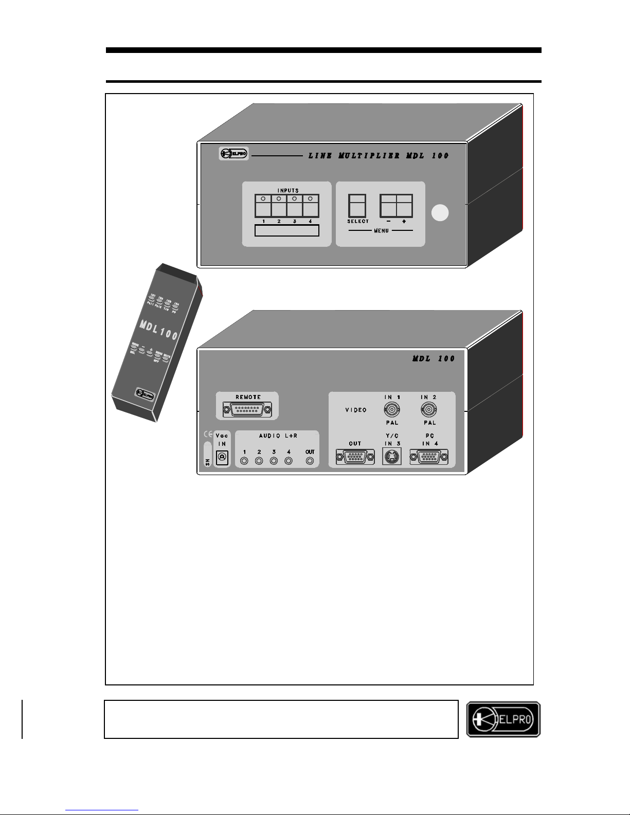
MDL 100
LINE MULTIPLIER AND SWITCHER
•
4 INPUTS WITH ASSOCIATED AUDIO
•
WIDE RANGE OF CORRECTIONS AND ADJUSTMENTS
•
VIDEO/AUDIO MUTE FUNCTION
•
ON SCREEN MENU (OSD)
•
MAINTENANCE OF SETTINGS
•
RECALLABLE PRESETTINGS
•
FULLY CONTROLLED BY PC
•
IR CONTROL OPTIONAL
Page 2

I
NDEX:
1.0 Overview
2.0 Power supply
3.0 Pre-settings
4.0 Installation
5.0 Source selection
6.0 OSD functions
7.0 Controls with dry contacts and tally
8.0 Computer control
9.0 Accessories
10.0 Technical data
11.0 Notes
When installing the MDL100 unit always read this handbook carefully.
The manufacturer shall not be held responsible for damages or injury
resulting from use, even correct, of its products.
Product data and charact eri stics may be changed without prior notice.
11.0 NOTES
This product is guaranteed for 2 years from date of purchase.
The warranty is null and void if the fault in the product is due to
During the warranty period, ELPRO will repair the faulty units free of charge.
The faulty units must be sent CARRIAGE FREE to the ELPRO offices of
TURIN with a regular accompanying note.
The units will be returned CARRIAGE FORWARD to the addressee.
Outside the warranty period, ELPRO will repair the faulty units EX its TURIN
offices with debiting of the cost of the repair to the customer.
INSTALLATION AND USE OF THE MDL100
MDL 100
MDL 100
LINE MULTIPLIER AND SWITCHER
2
ELPRO BROADCAST s.r.l.
Strada della Pronda 17 - TORINO (ITALY)
Tel. 0117071955 - FAX 011706210
Page 3
1.0 OVERVIEW
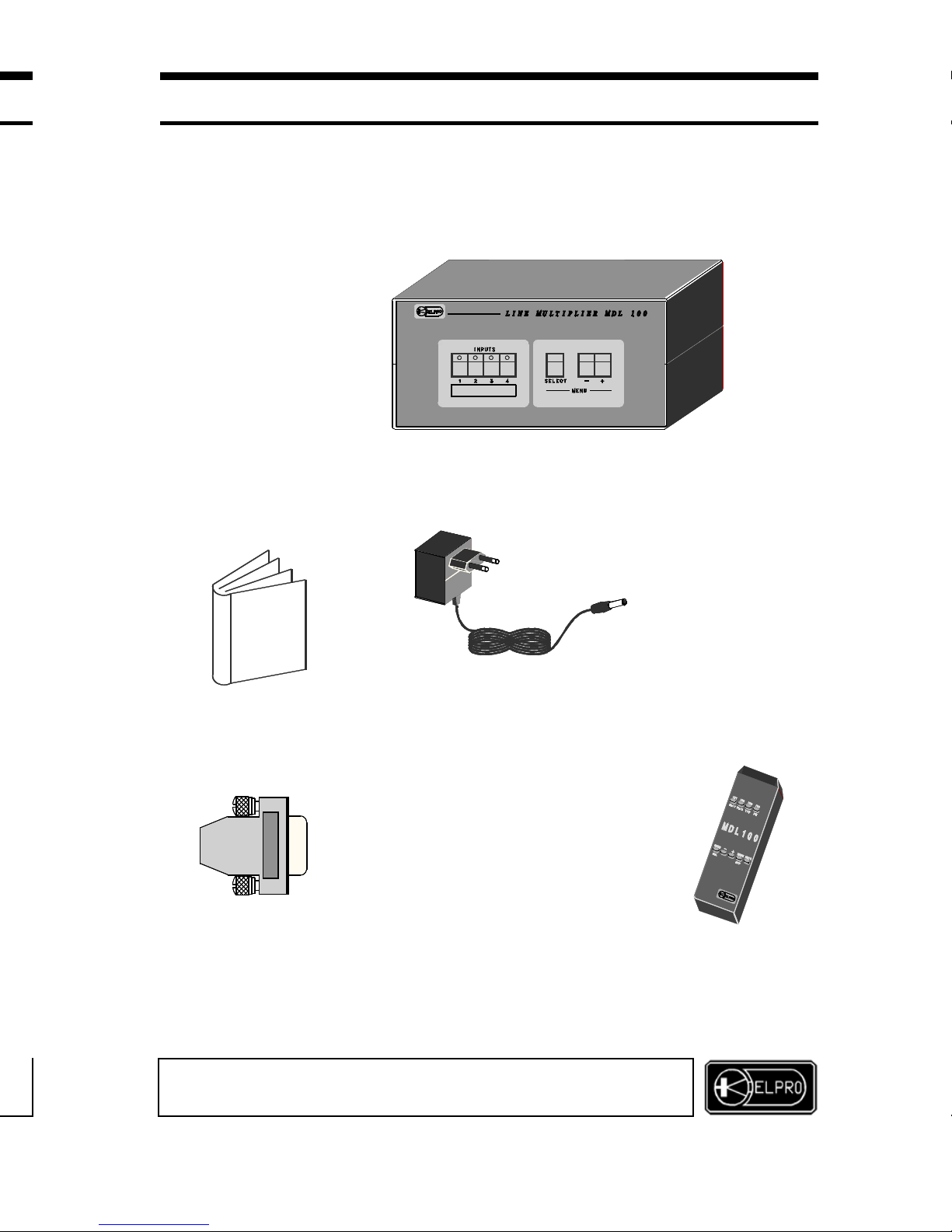
Thank you for buying this product. Che ck the contents of the packagi ng
carefully.
It contains:
3
ELPRO BROADCAST s.r.l.
Strada della Pronda 17 - TORINO (ITALY)
Tel. 0117071955 - FAX 011706210
MDL 100
LINE MULTIPLIER AND SWITCHER
The MDL100 unit converts the standard TV signal into a high resolution
RGBHsVs graphic signal. It can be used to enhance image quality in the
case of video projection or display on monitor. The possibility of selecting
between 4 video inputs with related associated audio make the MDL100
very useful in multi-media presentations.
− The application diskette
for control b
y
PC
− N°1 sub-D15v.m. conn.
with cap code ADP010
− The mains adapter
code ADM001
− This handbook
− The MDL100 unit
− IR control
(op
tional)
Page 4
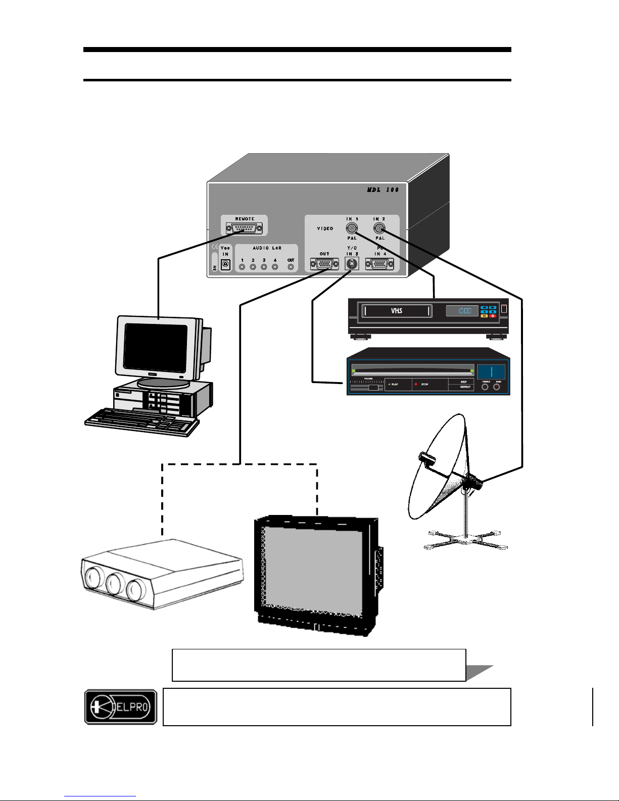
In a presentation system, it is very useful to have a single high resolution
RGBHsVs output toward the video projector, selecting the sources directly
from the MDL100.
7.2 Mute
The mute of the audio and blacking out of the screen are controlled using 2
separate dry contacts connected as indicated in the figure below.
The Mute function is active as long as the rela ted pin is grounded (pin 7)
8.0 COMPUTER CONTROLS
All functions of the MDL100 unit can be controlled by a computer.
The diskette with the application software is provided.
Connect the serial port of the computer as shown in the drawing below.
For installation, access and functions available in the software, read the
illustrative sheet provided with the diskette.
MDL 100
LINE MULTIPLIER AND SWITCHER
4
ELPRO BROADCAST s.r.l.
Strada della Pronda 17 - TORINO (ITALY)
Tel. 0117071955 - FAX 011706210
MDL 100 SYSTEM
Page 5
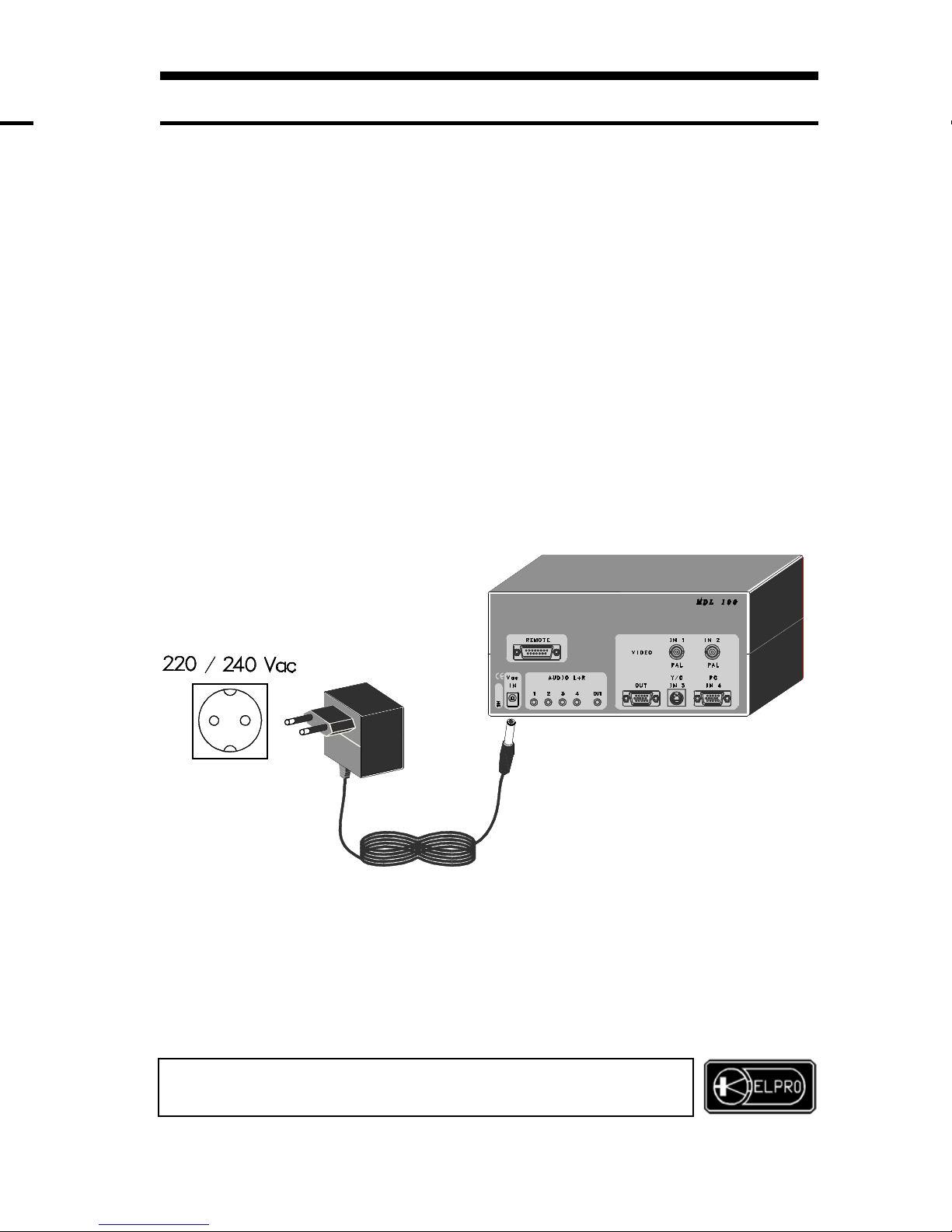
2.0 POWER SUPPLY
The MDL unit must be powered using only the AC/AC adapter code ADM 001
provided.
WARNING
Use of any other type of ad apter could damage the appliance.
The unit has no internal settings or pre-settings.
Any operations on the unit must be carried out
by qualified personnel only
The adapter must be inserted in a 22 0- 23 0 Vac/50 Hz AC outlet.
MDL 100
LINE MULTIPLIER AND SWITCHER
5
ELPRO BROADCAST s.r.l.
Strada della Pronda 17 - TORINO (ITALY)
Tel. 0117071955 - FAX 011706210
Page 6
3.0 PRE-SETTINGS
The unit has no jumper type hardware presettings. All variable functions are controlled
using the keyboard or OSD (On Screen Display) or using the PC whose connection
software is furnished with the unit.
4.0 INSTALLATION
a) Make sure that all the units to be installed are off.
b) Connect the
Pal
sources to the two BNC identified as IN1 and IN2
c) Connect the
Y/C
source to the mini-DIN connector identified as IN3
d) Connect the graphic source
(PC)
to the HDD15p.m. connector identified as IN4
WARNING
If more than 1 computer is to be connected to the system,
use a TZW403 type switcher connecting the
output of this to the IN4 input of the MDL100
e) Connect the destination (video projector or multiscan monitor) to the HDD15p. f.
connector identified as OUT using an ADC105 type high quality multi-coax cable.
WARNING
If the cable is more than 10 meters long,
it is advisable to insert an INBOX/4 type amplifier
f) Connect the stereo audio leading out of the 4 sources to the four 3.5mm jack outlets
identified as AUDIO L+R 1÷4
g) Take the stereo audio leading out of the OUT jack outlet and connect it to the sound
amplification and diffusion system.
h) If required, connect the control PC or the external control dry contacts as described
in chapters 7.0 and 8.0.
i) Co nnect the Vac power supply as specified in chapter 2,0 and check that the led of
the key referring to input 1 on the front of the unit lights up.
j) Power the sources and destination. The source connected to input IN1 must be
displayed in high resolution.
5.0 SOURCE SELECTION
Input 1 is activated automatically at power-on.
Selection of sources may be done either by the optional IR
control
6.0 OSD (ON SCREEN DISPLAY) FUNCTIONS
The
SELECT
OSD:
PICTURE ADJUST Makes it possible to modify the size of the image
BRIGHTN Makes it possible to modify brightness
CONTRAST Makes it possible to modify contrast
COLOURS Makes it possible to modify saturation of colours
MUTE AUDIO Clears the level of the output audio
MUTE VIDEO Darkens the image
GAMMA CORRECT Inserts Gamma correction on the RGB signals
BORDER COLORS Makes it possible to define the color of the border
BORDER VISIBLE Inserts the border on the image
ADVA NCED FUNCTION:
HOR SYNC Setting of the polarity of the H synchronism
VER SYNC Setting of the polarity of the V synchronism
ALIASING Insertion of the anti-aliasing filter on the input signal
INPUT AMPLIF Change the amplitude of the input signal
FILTER Inserts a filter on the luminance
MDL 100
LINE MULTIPLIER AND S WI T CHER
ELPRO BROADCAST s.r.l.
Strada della Pronda 17 - TORINO (ITALY)
Tel. 0117071955 - FAX 011706210
6 7
Page 7
5.0 SOURCE SELECTION
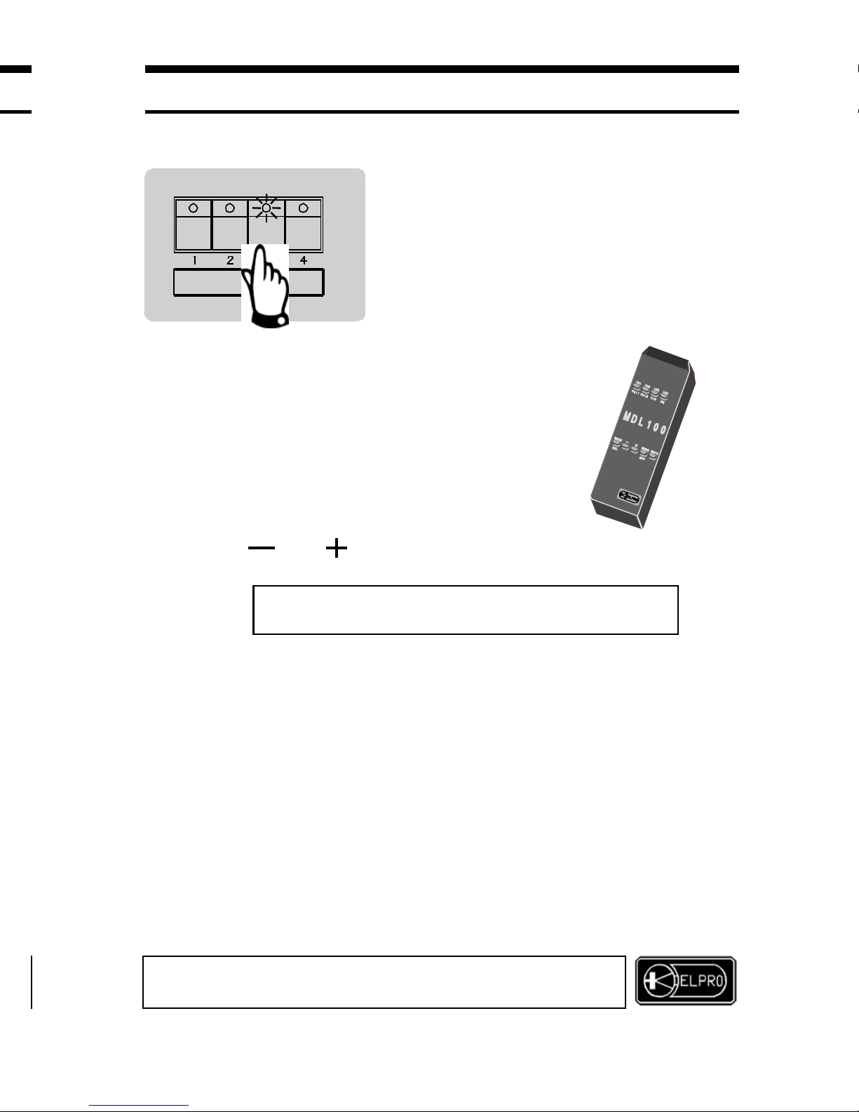
The sources are selected press ing one of the 4 keys
identified as INPUTS 1-4 on the built-in console of
the unit. Switching on of the led incorporate d in the
key indicates which source is processed and
activated on the output.
WARNING
If source 4 (PC) is selected, this transits
toward the output without any processing.
Input 1 is activated automatically at power-on.
Selection of sources may be done either by the optional IR
control
6.0 OSD (ON SCREEN DISPLAY) FUNCTIONS
The
SELECT
and
MENU keys can be used to set the following functions using
OSD:
PICTURE ADJUST Makes it possible to modify the size of the image
BRIGHTN Makes it possible to modify brightness
CONTRAST Makes it possible to modify contrast
COLOURS Makes it possible to modify saturation of colours
MUTE AUDIO Clears the level of the output audio
MUTE VIDEO Darkens the image
GAMMA CORRECT Inserts Gamma correction on the RGB signals
BORDER COLORS Makes it possible to define the color of the border
BORDER VISIBLE Inserts the border on the image
ADVA NCED FUNCTION:
HOR SYNC Setting of the polarity of the H synchronism
VER SYNC Setting of the polarity of the V synchronism
ALIASING Insertion of the anti-aliasing filter on the input signal
INPUT AMPLIF Change the amplitude of the input signal
FILTER Inserts a filter on the luminance
ELPRO BROADCAST s.r.l.
Strada della Pronda 17 - TORINO (ITALY)
Tel. 0117071955 - FAX 011706210
MDL 100
LINE MULTIPLIER AND SWITCHER
7
INPUTS
The On Screen Display is activected pressing for 1 sec.
the pushbutton SELECT
Page 8
SPECIAL EFFECTS:
FILTER R Red picture
FILTER G Green picture
FILTER B Blue picture
NEGATIVE IMAGE Displays the image in negative
DIGITIZ IMAGE Reduces the quantization of the image (Solarization)
NORMAL IMAGE Removes all special effects
DEFAULT VALUE Resets the image to the standard parameters
MENU END
7.0 CONTROL WITH DRY AND TALLY CONTACTS
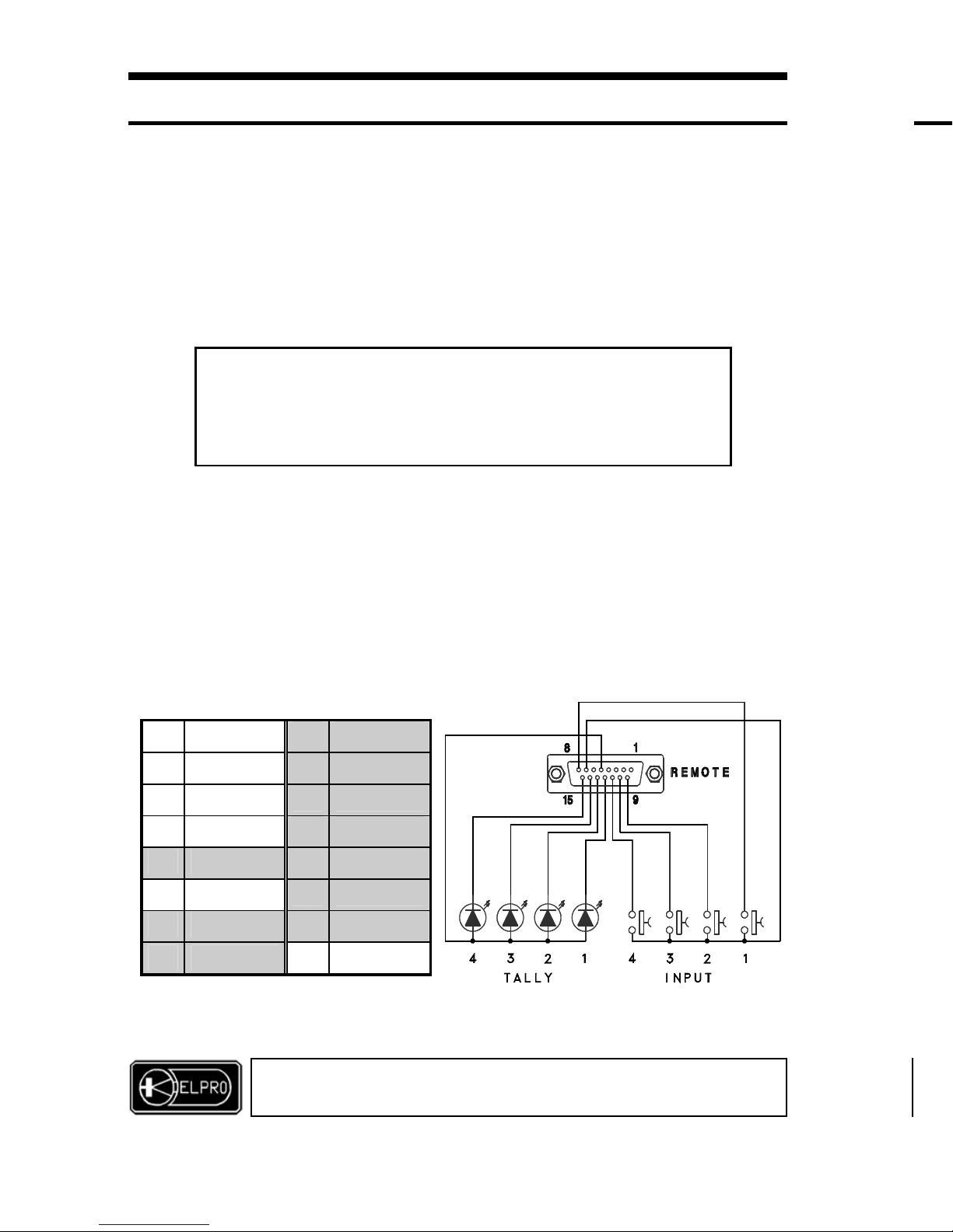
The MDL100 can be controlled using dry contacts connected to the sub-D 15v.f.
connector identified as REMOTE and present on the rear of the machine.
7.1 Source selection
The source to be processed and sent to the output can be selected using 4 dry
contacts connected as indicated in the figure below. Four external signals for
switching on of the 4 tally leds are also provided.
Connect
external
contacts and leds as indicated in the table and draft.
WARNING
For the best results use high efficiency leds
2.0 POWER SUPPLY
The MDL unit must be powered using only the AC/AC adapter code ADM 001
provided.
Use of any other type of ad apter could damage the appliance.
The adapter must be inserted in a 22 0- 23 0 Vac/50 Hz AC outlet.
MDL 100
LINE MULTIPLIER AND S WI T CHER
8
1
RS232TX
9 INPUT 2
2
RS232RX
10 INPUT 3
3
- 11 INPUT 4
4
MUTE AUDIO
12 TALLY 1
5 +5 VDC 13 TALLY 2
6
MUTE VIDEO
14 TALLY 3
7 GND 15 TALLY 4
8 INPUT 1
-
ELPRO BROADCAST s.r.l.
Strada della Pronda 17 - TORINO (ITALY)
Tel. 0117071955 - FAX 011706210
The exit from On Screen Display is
obtained pressing for 1 sec. the pushbutton SELECT
Or
Selecting the MENU END item
(in this case the value imposed are stored in memory)
Page 9
7.2 Mute
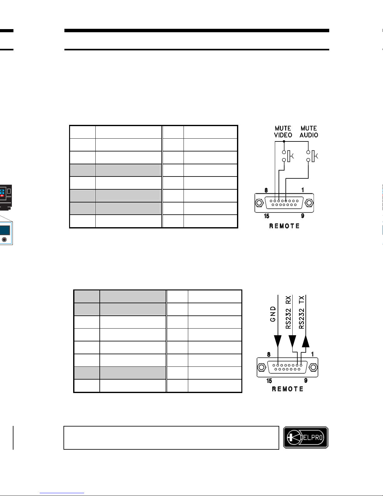
The mute of the audio and blacking out of the screen are controlled using 2
separate dry contacts connected as indicated in the figure below.
WARNING
The Mute function is active as long as the rela ted pin is grounded (pin 7)
8.0 COMPUTER CONTROLS
All functions of the MDL100 unit can be controlled by a computer.
The diskette with the application software is provided.
Connect the serial port of the computer as shown in the drawing below.
For installation, access and functions available in the software, read the
illustrative sheet provided with the diskette.
MDL 100
LINE MULTIPLIER AND SWITCHER
ELPRO BROADCAST s.r.l.
Strada della Pronda 17 - TORINO (ITALY)
Tel. 0117071955 - FAX 011706210
1
RS232TX
9 INPUT 2
2
RS232RX
10 INPUT 3
3
-
11 INPUT 4
4
MUTE AUDIO
12 TALLY 1
5 +5 VDC 13 TALLY 2
6
MUTE VIDEO
14 TALLY 3
7 GND
15 TALLY 4
8 INPUT 1 -
1 RS232TX
9 INPUT 2
2 RS232RX
10 INPUT 3
3
-
11 INPUT 4
4 MUTE AUDIO 12 TALLY 1
5 +5 VDC 13 TALLY 2
6 MUTE VIDEO 14 TALLY 3
7 GND
15 TALLY 4
8 INPUT 1 -
Page 10
9.0 ACCESSORIES
The following are provided with the MDL100 unit:
- Mains adapter code ADM001
- N°1 sub-D15v.m. connector with cap code ADP010
- The application diskette for control from PC
The following are available on request:
- VGA cable for connection of the variable length destination (see list of accessories ) .
- IR control
10.0 TECHNICAL DATA
Main input (with AC adapter ADM001) :230 Vac 50 Hz
Power consumption :5 VA
Size (WXDXH) :220x105x120 mm
Weight :0.8 Kg.
Operating temp.range :0÷45°C
Safety :according to EN 60065
EMC : according to EN 555013 and EN 55020
mark
1.0 OVERVIEW
Thank you for buying this product. Che ck the contents of the packagi ng
carefully.
It contains:
10
MDL 100
LINE MULTIPLIER AND SWITCHER
ELPRO BROADCAST s.r.l.
Strada della Pronda 17 - TORINO (ITALY)
Tel. 0117071955 - FAX 011706210
VIDEO
Inputs :N°2 Pal with BNC
N°1 Y/C with Mini-Din
N°1 PC (bypass) with
HDD15p.m.
Output :High resolution RGBHsVs with
HDD15p.f.
Sync level :TTL
Sync polarity :selectable
AUDIO
Inputs :N°4 stereo with 3.5mm jack
Input coupling :AC, unbalanced
Input impedance :47KΩ
Input level :+11 dBm Max.
Gain :-0.5dB
Freq. response :-1dB from 40Hz to 20KHz
Crosstalk :60 dB at 5 KHz
Distortion :<0.03% at 0dBm with 10KΩ load
Output load :10KΩ nominal, 600Ω min.
Out
p
ut impedance :100
Ω
SETTINGS (by OSD or soft.control):
Picture size adj.
Gamma correction
Lum., Contrast, Saturation
Mute video/audio
Gamma correction
Border
A
dvanced functions
Image enhancement
Filter and special effects
Page 11

11.0 NOTES
This product is guaranteed for 2 years from date of purchase.
The warranty is null and void if the fault in the product is due to
improper use or operations by third parties
During the warranty period, ELPRO will repair the faulty units free of charge.
The faulty units must be sent CARRIAGE FREE to the ELPRO offices of
TURIN with a regular accompanying note.
The units will be returned CARRIAGE FORWARD to the addressee.
Outside the warranty period, ELPRO will repair the faulty units EX its TURIN
offices with debiting of the cost of the repair to the customer.
For any problems during installation of the MDL100,
use the Elpro hot-line +039 011 705835
or E-mail: [email protected]
MDL 100
LINE MULTIPLIER AND SWITCHER
ELPRO BROADCAST s.r.l.
Strada della Pronda 17 - TORINO (ITALY)
Tel. 0117071955 - FAX 011706210
11
Page 12

INDEX OF ACCESSORIES INFOVIDEO LINE
Cod. ELPRO Description
− ADC 101 Cable HDD 15 p. m./f. 1,5 mt.
− ADC 105 Cable HDD 15 p. m./f. 5,0 mt.
− ADC 110 Cable HDD 15 p. m./f. 10,0 mt.
− ADC 120 Cable HDD 15 p. m./f. 20,0 mt.
− ADC 130 Cable HDD 15 p. m./f. 30,0 mt.
− ADC 201 Adapter cable HHD 15 p. m./5 BNC
− ADC 301 MAC Adapter cable DB 15 p. f./HHD 15 p. m.
− ADC 401 SUN Adapter cable 13W3 f./HHD 15 p. m.
− ADC 402 SUN Adapter cable 13W3 m./HHD 15 p. f.
− ADC 501 SGI Adapter cable 13W3 f./HHD 15 p. m.
− ADC 502 SGI Adapter cab l e 13W 3 m./HHD 15 p. f.
− ADC 610 RG 59B/U cable BNC/ BNC 10mt.
− ADC 630 RG 59B/U cable BNC/ BNC 30mt.
− ADC 665 RG 59B/U cable BNC/ BNC 65mt.
− ADC 710 Cable for TCR 03 DB 15 p. m. /f. 10mt.
− ADM 001 AC Adapter
− ADP 010 Connector DB 15 p. m. with cover
− ADP 101 VGA Adapter m./m.
− ADP 102 VGA Adapter f./f.
− ADP 302 MAC Adapter plug DB 15 p. m./HHD 15 p. f.
− ADR 2U Rack adapter 2U
− ADR 3U Rack adapter 3U
− ADR 2U BLK Blank panel 2U
−
ADR 3U BLK Blank panel 3U
ELPRO BROADCAST s.r.l.
Strada della Pronda 17 - TORINO (ITALY)
Tel. 0117071955 - FAX 011706210
12 1
ELPRO BROADCAST s.r.l.
 Loading...