

Page 1
LIN101
RS232 / LAN INTERFACE
ELPRO Video Labs s.r.l.
Via della Praia 4/a FERRIERA di BUTTIGLIERA ALTA (TO) - ITALY
Tel. +39 0119348778 - FAX +39 0119348779
1
LIN101
RS232 / LAN INTERFACE
24/02/2004 English
Page 2
LIN101
RS232 / LAN INTERFACE
ELPRO Video Labs s.r.l.
Via della Praia 4/a FERRIERA di BUTTIGLIERA ALTA (TO) - ITALY
Tel. +39 0119348778 - FAX +39 0119348779
2
1. LIN101
LIN101 is a Serial Device Server, the main function of the LIN101 is to network-enable existing serial devices.
Using the LIN101 you can add an Ethernet port practically to any serial device with RS232 interface. It is possible to
communicate with any serial device from any PC (or other device) connected to the LAN.
If the LAN has a direct connection to the Internet, then the serial device is accessible from anywhere in the world.
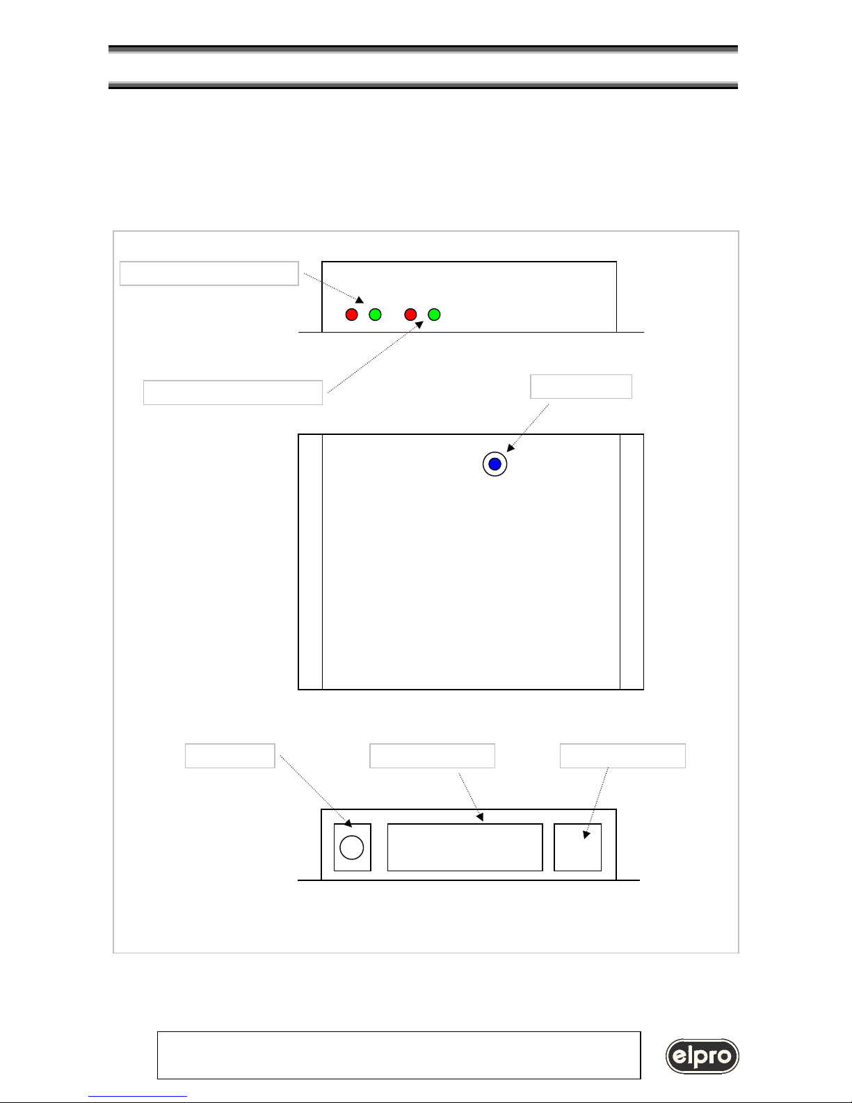
LED 1 and 2: LIN101 Status
LED 3 and 4: Ethernet Status
SETUP Button
9 Vac Power
RS232 Connector
Ethernet Connector
LIN101
Page 3
LIN101
RS232 / LAN INTERFACE
ELPRO Video Labs s.r.l.
Via della Praia 4/a FERRIERA di BUTTIGLIERA ALTA (TO) - ITALY
Tel. +39 0119348778 - FAX +39 0119348779
3
1.1 LIN101 usage
There are three basic ways to communicate with the LIN101:
• with a serial device controlled via the network using an existing PC software, then you can use the LIN101 to
network-enable this serial device and communicate with it from the PC through our Virtual Serial Port Driver
(VSPD). Virtual Serial Ports (VSPs) created by the driver are logical COMs that behave like standard hardware
COMs but in reality transparently reroute the data via the TCP/IP network to the LIN101-enabled serial device.
VSPs allow you to continue using your existing PC software without any modification.
• with a serial device and you are creating a new PC software to control it then you can develop software that
communicates with the LIN101 directly (without VSPD). The LIN101 transmits the data using industry-standard
UDP/IP and TCP/IP communications protocols.
• it is possible to create a virtual serial link over the network by using the LIN101-enabled serial device on one
side and the LIN101 Serial Device Server on the other side.
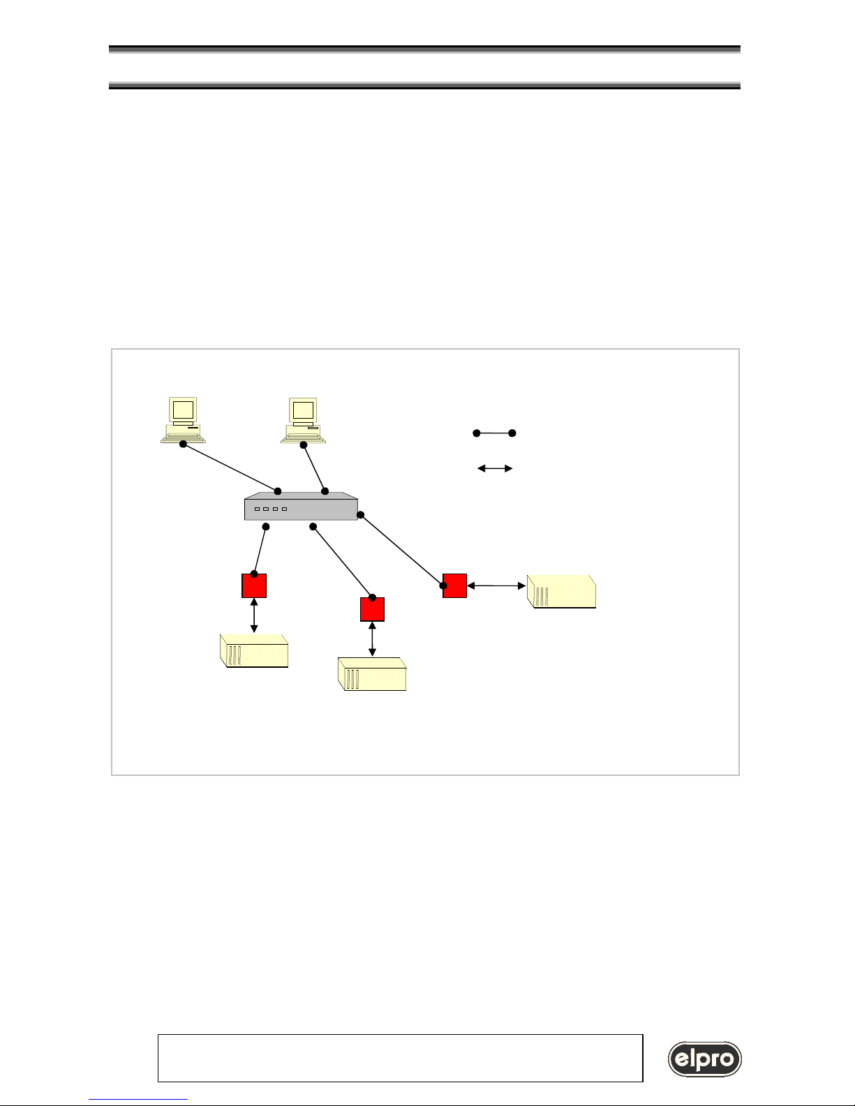
PC with VSPD software in Windows environment
HUB
Ethernet connections
RS232 connections
LIN101
TZ333
TZ333
TZX08
PC Ethernet LAN with VSPD software
virtual
virtual
COMx
Page 4
LIN101
RS232 / LAN INTERFACE
ELPRO Video Labs s.r.l.
Via della Praia 4/a FERRIERA di BUTTIGLIERA ALTA (TO) - ITALY
Tel. +39 0119348778 - FAX +39 0119348779
4
1.2 Operating modes
LIN101 has two operating modes:
• Normal Mode: is entered after the powerup, it is in the Normal Mode that the LIN101 performs its
Etherne/Serial data routing. Network Programming of the LIN101 can also proceed in the Normal Mode in
parallel with the data routing
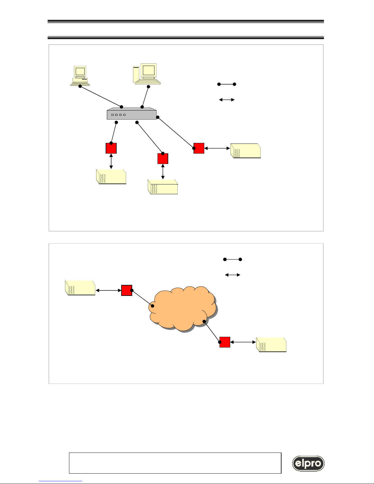
Computer without VSPD software (NON PC environment, other OS like LINUX etc.)
HUB
Ethernet connections
RS232 connections
LIN101
TZ333
TZ333
TZX08
Ethernet LAN without usin
g VSPD software
Serial devices over the network connected by 2 LIN101
L
IN101
LIN101
LAN Ethernet
Ethernet connections
RS232 connections
Serial Device
Serial Device
Page 5
LIN101
RS232 / LAN INTERFACE
ELPRO Video Labs s.r.l.
Via della Praia 4/a FERRIERA di BUTTIGLIERA ALTA (TO) - ITALY
Tel. +39 0119348778 - FAX +39 0119348779
5
• Serial Programming Mode: is entered pressing the SETUP button or escape sequence is sent into the LIN101
serial port while the LIN101 is in the Normal Mode. This mode is used to program the LIN101’s functioning
parameters (Settings) via the serial port
1.3 Status LED signals
The LIN101 has two pairs of leds that provide a visual indication:
LED1 and LED 2: LIN101 Status
At startup in Normal Mode Green and red LEDs blink 3 times
Setting error (cannot enter the Normal Mode) Red LED blink
Normal Mode active: Slave Routing Mode Green LED constantly ON
Normal Mode active: Master Routing Mode (*)
• Destination IP-address not reachable
Green LED blink
• Destination IP-address reachable
Green LED constantly ON
Buffer overflow Green and red LEDs blinking constantly
(*) The LIN101 is constantly sending pings to the Destination IP-address when in the Master Routing
Mode (once in every 5 seconds). The Green Status LED is blinking if no reply is received. The Green Status
LED is constantly on when the destination replies to pings.
LED3 and LED4: Ethernet status
Green LED RX
normally ON, turned off when is receiving Ethernet packets
Red LED COLLISION
normally OFF, turned on when there is a darta collision on the Ethernet network
Page 6
LIN101
RS232 / LAN INTERFACE
ELPRO Video Labs s.r.l.
Via della Praia 4/a FERRIERA di BUTTIGLIERA ALTA (TO) - ITALY
Tel. +39 0119348778 - FAX +39 0119348779
6
2. Operation in Normal Mode
The main function of the LIN101 is to route the data between its Ethernet and serial ports. Routing means that the data
received into the serial port is sent out via the Ethernet port and vise versa. Data routing is effected through two routing
buffers, one for each routing direction. The LIN101 performs the routing in the Normal Mode of operation. A number of
user-programmable Settings and Parameters define the way the LIN101 works in the Normal Mode.
2.1 Ethernet port and network communications
The Ethernet port of the LIN101 is of 10BaseT type. Just like any other Ethernet device each LIN101 has a unique
Ethernet (MAC) Address and must be assigned a valid IP-address to function properly on the network.
Logically, the LIN101’s network interface has two ports. A user-definable Data Port is used to exchange the data
between the LIN101 and other stations on the network. Another port called Command Port has a fixed number 65535
(FFFF Hex) and is used to send programming commands to the LIN101’s over the network.
The LIN101 can exchange data with remote stations using the UDP/IP or TCP/IP transport protocols as
defined by the Transport Protocol Setting. Depending on the Routing Mode Setting the LIN101 can act as a
network Slave or Master (see Slave and Master routing modes for details).
Other network-related settings include Destination IP-address, Destination Data Port Number, Gateway
IP-address, Netmask, and Connection Timeout.
2.2 Serial comunications
The serial port of the LIN101 supports TX, RX, CTS, and RTS signals and can work at baudrates up to 115200. In the
Normal Mode the serial port transmits the data between the LIN101 and attached serial device (microcontroller). In the
Serial Programming Mode the port is used to program the LIN101’s Settings. Settings that define the operation of the
serial port include the Baudrate (150~115200bps), Parity (none, even, or odd), Bits Per Byte (7 or 8), and Flow Control
(none or CTS/RTS). Each of these Settings has a matching Parameter that overrides the value of a corresponding
Setting.
2.3 Routing buffers
The data between the Ethernet port and the serial port is routed via two independent 255-byte buffers, one for each
routing direction. Buffers are necessary because the Ethernet and the serial port operate at different speeds and in
different ways. Ethernet carries the data in “packets” (i.e. groups of data), while the serial port sends and receives a
serial “stream” where each data byte is independent. Here is how the LIN101 transforms the Ethernet packets into the
serial stream and back:
• Ethernet serial data routing is simple: the LIN101 outputs the contents of arriving Ethernet data packets byte by byte
via the serial port. The LIN101 does not check of filter the contents of data being routed in the Ethernet -> serial
direction
• Serial Ethernet routing requires grouping arriving serial data into packets and is more complicated. Several Settings
define exactly what serial data is accepted into the buffer and when and how this data is combined into an Ethernet
packet and sent out. Detailed information on the subject can be found in Serial -> Ethernet data routing.
Page 7

LIN101
RS232 / LAN INTERFACE
ELPRO Video Labs s.r.l.
Via della Praia 4/a FERRIERA di BUTTIGLIERA ALTA (TO) - ITALY
Tel. +39 0119348778 - FAX +39 0119348779
7
3 Slave and Master routing modes
The LIN101 routes the data in one of two modes as defined by the Routing Mode Setting:
• In the Slave Routing Mode the LIN101 never sends any data transmission in the serial port -> Ethernet direction
before it receives some data from the remote station first (i.e. the data in the Ethernet -> serial direction). The
serial data received into the LIN101’s serial port before the remote station “contacts” the LIN101 is discarded. In
the Slave Mode the LIN101 will “work” with any station on the network that contacts it
• In the Master Routing Mode the LIN101 does not wait for the remote station to send the data first and routes the
data in the serial -> Ethernet direction as soon as there is a data to be sent. The data is always sent to a
specific destination (as defined by the Destination IP-address and Destination Data Port Number Settings of the
LIN101). Also, the LIN101 only accepts the data sent from the remote station whose IP-address matches the
one set in the Destination IP-address. The LIN101 will discard the data sent from any other IP. Note, that data
port number of the sender is not verified so the data can be sent from any port.
3.1 Using Slave and Master Routing Modes
Use the Slave Routing Mode to network-enable serial devices that never send out the data by themselves but instead
are “polled” for data from the PC. Examples of such devices are time recorders, access control panels and other
“hardware terminals”.
Use the Master Routing Mode to network-enable serial devices that send out the data “spontaneously” i.e. without
waiting for the request from PC.
Also use the Master Routing Mode in cases when the serial data must flow independently in both directions (i.e. Ethernet
-> serial and serial -> Ethernet). This is the case, for instance, when you are creating a “network modem” that must pass
the data in both directions simultaneously.
3.2 Required network settings for the Slave and Master Routing Modes
In the Slave Routing Mode the LIN101 only “responds” to other stations on the network. When the LIN101 receives the
data from remote station it memorizes this station’s IP-address and data port number. When routing the data in the serial
-> Ethernet direction the LIN101 will reply to this IP-address and data port number. Therefore, the only network settings
that must be set in the Slave Routing Mode are the LIN101’s own IP-address and the Data Port Number. This is true
even if there is a router between the remote station and the LIN101. You don’t have to set the Netmask
and Gateway IP when using the LIN101 in the Slave Routing Mode;
In the Master Routing Mode the LIN101 needs to be able to send the data to a predefined remote station at any time.
This means that not only LIN101’s own IP-address and Data Port Number must be set but also the Destination IPaddress and the Destination Data Port Number. If the destination remote station and the LIN101 are residing in different
network segments then the Netmask and Gateway IP-address must also be set.
3.3 Slave and Master routing modes vs. UDP/IP and TCP/IP transport protocols
UDP/IP and TCP/IP provide completely different data transmission so LIN101s behavior in the Slave and Master Routing
Modes is slightly different under UDP/IP and TCP/IP Transport Protocols.
• UDP/IP Transport Protocol
o Slave Routing Mode.
All UDP data packets arriving from any remote station and addressed to the Data Port of the LIN101
are routed to the serial port. For the serial -> Ethernet direction the LIN101 always sends the data to
the IP-address and the port number that were received in the last (latest) UDP packet. Once the
LIN101 receives a UDP packet from a different station it will start sending all its serial -> Ethernet data
to this new station. After power up and before the LIN101 receives the first UDP data packet the
LIN101 doesn’t have any IP-address and port number to send the data to so all the data received into
the LIN101’s serial port is simply discarded.
o Master Routing Mode.
The LIN101 only accepts and routes to the serial port the data packets that have originated from the
remote station whose IP-address matches the one defined by the Destination IP-address Setting.
Source data port number need not match the one defined by the Destination Data Port Number Setting
Page 8

LIN101
RS232 / LAN INTERFACE
ELPRO Video Labs s.r.l.
Via della Praia 4/a FERRIERA di BUTTIGLIERA ALTA (TO) - ITALY
Tel. +39 0119348778 - FAX +39 0119348779
8
so the packet can be sent from any port. Whenever the LIN101 has the data to transmit in the serial ->
Ethernet direction it will send the data to the Destination IP-address and Destination Data Port Number.
The packet will be sent to the Destination Data Port Number even if the packet received by the LIN101
from the remote station originated at a different port. Therefore, it possible that the LIN101 will be
receiving the data from one port but sending it to another port!
• TCP/IP Transport Protocol
o Slave Routing Mode.
The LIN101 will accept an incoming TCP connection from any station on the network. The LIN101 will
not attempt to establish a connection with a remote station by itself even it the LIN101 has the data to
transmit in the serial -> Ethernet direction. Once the remote station has established the connection the
data can flow independently in either direction. Pending serial -> Ethernet data received by the LIN101
prior to the TCP connection establishment is discarded when the connection is established.
o Master Routing Mode.
The LIN101 will both accept an incoming TCP/IP connection and attempt to establish a connection with
the remote station by itself depending on which side sends that data first- remote station or attached
serial device. Incoming TCP connection will only be accepted from a station whose IP-address
matches the one defined by the Destination IP-address Setting of the LIN101. Source port number
need not match the one defined by the Destination Data Port Number Setting so the connection can be
initiated from any port. When the LIN101 needs to initiate a TCP/IP connection the it will attempt to
connect to the Destination IP-address and Destination Data Port Number. Once the connection has
been established the data can flow independently in either direction. Note that unlike in case of UDP/IP
there will never be a situation when the LIN101 receives the data from one port but sends the data to
another port. Once the TCP/IP connection has been established both sides exchange the data using a
single port on each side.
3.4 Connections with more than two nodes
In many real-life situations it is often necessary to have several PCs (network stations) access the same serial device
through the LIN101 (“many clients to one data source”) or have many serial devices (each connected to the network via
its own LIN101) send the data to a single PC (“many data sources to one client”).
• Many clients to one data source operation is achieved by using the LIN101 in the Slave Routing Mode. The
LIN101 will reply to any sender in this mode, so any station will be able to access the host serial device with the
LIN101 inside.
o UDP/IP Transport Protocol should not be used if there is a chance that several different clients will send the
requests to the same LIN101/serial device at the same time. Data mix up will result on the serial side and
the LIN101 won’t be able to route the data back to the respective sender of each command correctly.
o TCP/IP Transport Protocol can be used safely since when one client is already connected to the LIN101
others won’t be able to gain access to the same LIN101 until this client disconnects. To prevent one client
from holding the TCP/IP connection to the LIN101 indefinitely there is a Connection Timeout Setting that
defines after how long the LIN101 will abort the connection in case there is no data transfer in any direction.
• Many data sources to one client operation is achieved by using the LIN101 in the Master Routing Mode. In
this mode the LIN101 will route all its serial -> Ethernet data to the Destination IP-address and Destination Data
Port Number. Any number of LIN101s can be set to send the data to the same destination.
o UDP/IP Transport Protocol can be used in this arrangement but you must make sure that each serial data
block output by the serial device is sent out in a single UDP packet. Potential data mix up can occur on the
receiving end if the serial data block is transmitted in several UDP packets and several LIN101 are sending
data at the same time. The upside of using the UDP/IP is that you will only need to maintain one listening
socket on the receiving end to get the data from all data sources (unless, of course, you want to distinguish
between the data sources). Several LIN101’s Settings define how the incoming serial data is combined into
Ethernet packets so you can make sure that the serial data block from is not split into several packets (see
serial -> Ethernet data routing for details).
o TCP/IP Transport Protocol can be used safely but you will have to maintain a separate socket on the
receiving end for every data source sending the data.
4 Serial to Ethernet data routing
Page 9

LIN101
RS232 / LAN INTERFACE
ELPRO Video Labs s.r.l.
Via della Praia 4/a FERRIERA di BUTTIGLIERA ALTA (TO) - ITALY
Tel. +39 0119348778 - FAX +39 0119348779
9
The LIN101 provides a way to choose which incoming serial data is accepted into the serial -> Ethernet
buffer, how this data is combined into Ethernet packets and when it is sent out via the Ethernet port.
The LIN101 treats all incoming serial data as a sequence of data blocks. The term “data block” here does not mean that
the LIN101 is only capable of working with a structured serial data. An absolutely random serial stream can also be
processed- as one continuous infinite serial data block. Serial data blocks begin when a start condition is detected and
end when a stop condition is detected. After the start condition is detected the LIN101 begins recording the incoming
serial data into the serial -> Ethernet buffer. Thus, the start condition is said to open the serial data block. When the stop
condition is detected the LIN101 seizes recording the data into the buffer and attempts to send out all the data
accumulated in the buffer via the Ethernet port. Therefore, the stop condition closes the serial data block. The inter-block
serial data i.e. the data received after the stop condition is detected and before the next start condition is detected is
discarded. Besides the start and stop conditions there is also a break condition. When the break condition is detected the
LIN101 doesn’t close the serial data block (i.e. it continues recording subsequent serial data into the serial -> Ethernet
buffer) but sends out the data already accumulated in the buffer through the Ethernet port. Break conditions provide a
way to subdivide large serial data blocks.
4.1 Start conditions
The Start On Any Character Setting defines if the LIN101 recognizes any character received into the serial port as a start
condition or requires a predefined Start Character to open the serial data block.
When Start On Any Character is set to “yes” the LIN101 will accept any character following the end of the previous serial
data block as the beginning of the next block. When Start On Any Character is set to “no” the LIN101 will only open the
serial data block when one of the preset Start Characters is received. Up to three different Start Characters can be
defined. Start Characters received after the serial data block has been opened are treated as normal characters and do
not “restart” the serial data block.
4.2 Stop conditions
Up to three different Stop Characters can be defined to close the serial data block. Once one of the preset Stop
Characters is detected the LIN101 closes the serial data block and attempts to send out the contents of the serial ->
Ethernet buffer via the Ethernet port. All subsequent serial data is ignored until the next start condition is met.
The use of Start Characters and Stop Characters assumes that these characters will not be encountered in the data
block body. Some communications protocols use checksums (or other forms of data integrity verification). Checksum can
potentially take any value and occasionally match the ASCII codes of the Stop Characters.
To avoid possible confusion some communications protocols put the checksum bytes behind the Stop Characters. The
LIN101 deals with this by allowing to define a Number Of Post-characters for each enabled Stop Character. For example,
if the Number Of Post-characters for a certain Stop Character is set to 2 then the LIN101 will additionally receive and
count as belonging to the current serial data block 2 bytes of data after this Stop Character has been encountered.
4.3 Break conditions
The Maximum Data Length Setting defines the maximum number of data bytes in the serial -> Ethernet buffer. (can be
set between 32 and 255). Once this number is reached the LIN101 attempts to send out the contents of the buffer via the
Ethernet port. This Setting only works when the UDP/IP Transport Protocol is selected. This is because TCP/IP has its
own way to determine what size of data chunks is best for transmission over the network.
The Maximum Intercharacter Delay Setting defines the maximum time gap between the arrival of two consecutive serial
characters into the serial port (can be defined in 10ms increments between 10ms and 2.55 sec). Once this time is
exceeded the LIN101 attempt to send out the contents of the serial -> Ethernet buffer via the Ethernet port. Setting the
maximum Intercharacter Delay to 0 disables the function.
4.4 Default configuration
The default configuration is the follow:
• Start On Any Character
• no Stop Characters are defined
• Maximum Intercharacter Delay is 10 ms
• Maximum Data Length is 255 byte (UDP only).
Page 10

LIN101
RS232 / LAN INTERFACE
ELPRO Video Labs s.r.l.
Via della Praia 4/a FERRIERA di BUTTIGLIERA ALTA (TO) - ITALY
Tel. +39 0119348778 - FAX +39 0119348779
10
As a result the very first byte received into the serial port is regarded as a beginning of the serial data block that never
ends. Once there amount of data in the serial -> Ethernet buffer reaches the limit or there is a gap in the serial
transmission the LIN101 combines all serial data it has already received and sends it out.
Practice shows that this arrangement works very well not only for a random data flow but also for
structured data.
4.5 Buffer-related issues
When using the LIN101 be careful not to overflow its internal Ethernet -> serial and serial -> Ethernet buffers. The
overflow can occur because of the difference in receive/transmission speeds on the Ethernet and the serial sides of the
LIN101 (Red Status LED blinks momentarily when overflow happens). In addition, the internal receiving buffer of the host
serial device can potentially overflow if the LIN101 outputs the serial data too fast.
• Ethernet -> Serial buffer
o UDP/IP Transport Protocol. The Ethernet -> serial buffer can easily overflow because the Ethernet is much
faster than the serial port and UDP/IP has no inbuilt protection against buffer overflows. UDP/IP should not
be used to send continuous data flow and is only suitable for sending short data blocks that can fit in the
buffer.
o TCP/IP Transport Protocol has an inbuilt protection from buffer overflowing. You can safely send the data of
any size.
• Serial -> Ethernet buffer
the only way to protect the buffer is to enable the RTS/CTS Flow Control in the LIN101 and on the host serial
device. This way the LIN101 will be able to signal the host serial device to stop transmitting the data once the
buffer becomes full.
• Internal receiving buffer of the host serial device.
this buffer can also be protected by using the RTS/CTS to regulate the exchange of data between the LIN101
and the serial device.
Note: using TCP/IP and RTS/CTS is the most reliable way of transmitting data through the LIN101
Page 11
LIN101
RS232 / LAN INTERFACE
ELPRO Video Labs s.r.l.
Via della Praia 4/a FERRIERA di BUTTIGLIERA ALTA (TO) - ITALY
Tel. +39 0119348778 - FAX +39 0119348779
11
5. LIN101 Programming
The operation of the LIN101 in the Normal Mode is controlled by a number of user-definable Settings and Parameters:
• Settings define the permanent functionality of the LIN101. Settings are stored in the non-volatile memory and
are preserved even when the LIN101 is switched off. After having been changed new Setting values take effect
only after the LIN101 is restarted (rebooted)
• Parameters are temporary overrides for certain Settings. Changing Parameters have an immediate effect on
the LIN101 operation. Parameters are preserved only until the LIN101 is switched off or restarted.
The LIN101 can be programmed in two different ways:
• Through the serial port of the LIN101 in a Serial Programming Mode
• Over the network using UDP packets sent to a command port 65535 (FFFF Hex). This method is called
Network Programming
There are several differences between the Serial Programming Mode and the Network Programming:
• Serial Programming Mode is a separate mode of operation. The LIN101 is not performing its data routing
function when in the Serial Programming Mode. In contrast the Network Programming is not a separate mode of
operation but a method of programming. Network Programming can proceed in parallel with the normal
operation of the LIN101.
• Certain commands can only be executed through the network. Some commands have different result when
executed in the Serial Programming Mode and through the network (Initialize command)
• Serial Programming Mode can always be entered, even when the LIN101 is not properly setup and needs to be
Initialized. Network Programming can only be used when the LIN101 is already functional.
5.1 LIN101 Programming using DST (Device Server Toolkit)
This software allows to handle many LIN101 connected in a Ethernet PC network. It creates Virtual Serial COMs on the
PC that can be used as harware installed COMs.
5.2 Programming via RS232
The Device Server Manager is a DST function taht allows to configure all LIN101 network settings or modify them by a
PC serial port or through the network
LIN101 programming can be done in a following manners:
• by PC serial communication port
• auto-discovery LIN101 connected in the network
• choosing a LIN101 from a predefined list
In the following example the LIN101 is programmed via RS232, the LIN101 will be connected in the network by HUB and
its serial port will exchange data with a serial device at 9600 bit/sec.
The LIN101 serial port must be connected to PC serial port with a cross-cable as follow:
PC side LIN101 side
(Tx) 3 2 (Rx)
(Rx) 2 3 (Tx)
(GND) 5 5 (GND)
(CTS) 8 7 (RTS)
(RTS) 7 8 (CTS)
Restart LIN101 and push the SETUP button on the bottom side (LIN101 status leds blink)
Now execute the DS Manager, the following window will be displayed
Page 12

LIN101
RS232 / LAN INTERFACE
ELPRO Video Labs s.r.l.
Via della Praia 4/a FERRIERA di BUTTIGLIERA ALTA (TO) - ITALY
Tel. +39 0119348778 - FAX +39 0119348779
12
Select the PC serial communication port connected to the LIN101.
Page 13

LIN101
RS232 / LAN INTERFACE
ELPRO Video Labs s.r.l.
Via della Praia 4/a FERRIERA di BUTTIGLIERA ALTA (TO) - ITALY
Tel. +39 0119348778 - FAX +39 0119348779
13
Network settings definition.
In this example the Slave Routing Mode is selected and the connection timeout is disabled, in this case the application
can control the serial device indefinitely.
Page 14
LIN101
RS232 / LAN INTERFACE
ELPRO Video Labs s.r.l.
Via della Praia 4/a FERRIERA di BUTTIGLIERA ALTA (TO) - ITALY
Tel. +39 0119348778 - FAX +39 0119348779
14
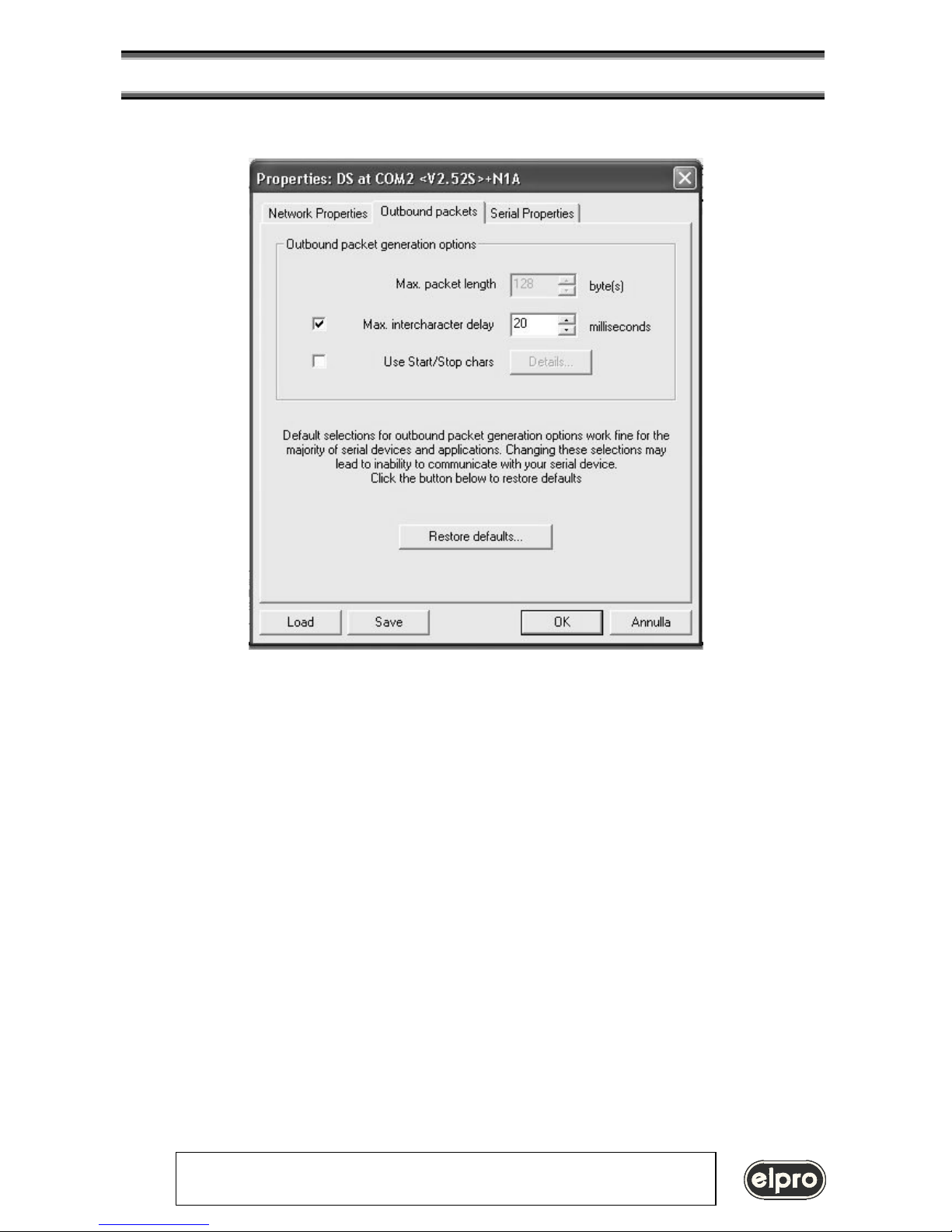
No Start and Stop condition are defined, then the TCP packet is completed after the 20 ms timeout as defined.
Page 15

LIN101
RS232 / LAN INTERFACE
ELPRO Video Labs s.r.l.
Via della Praia 4/a FERRIERA di BUTTIGLIERA ALTA (TO) - ITALY
Tel. +39 0119348778 - FAX +39 0119348779
15
Attached device serial port parameters:
All defined parameters are now sent to the LIN101, and It is possible to connect the LIN101 between the HUB and serial
device.
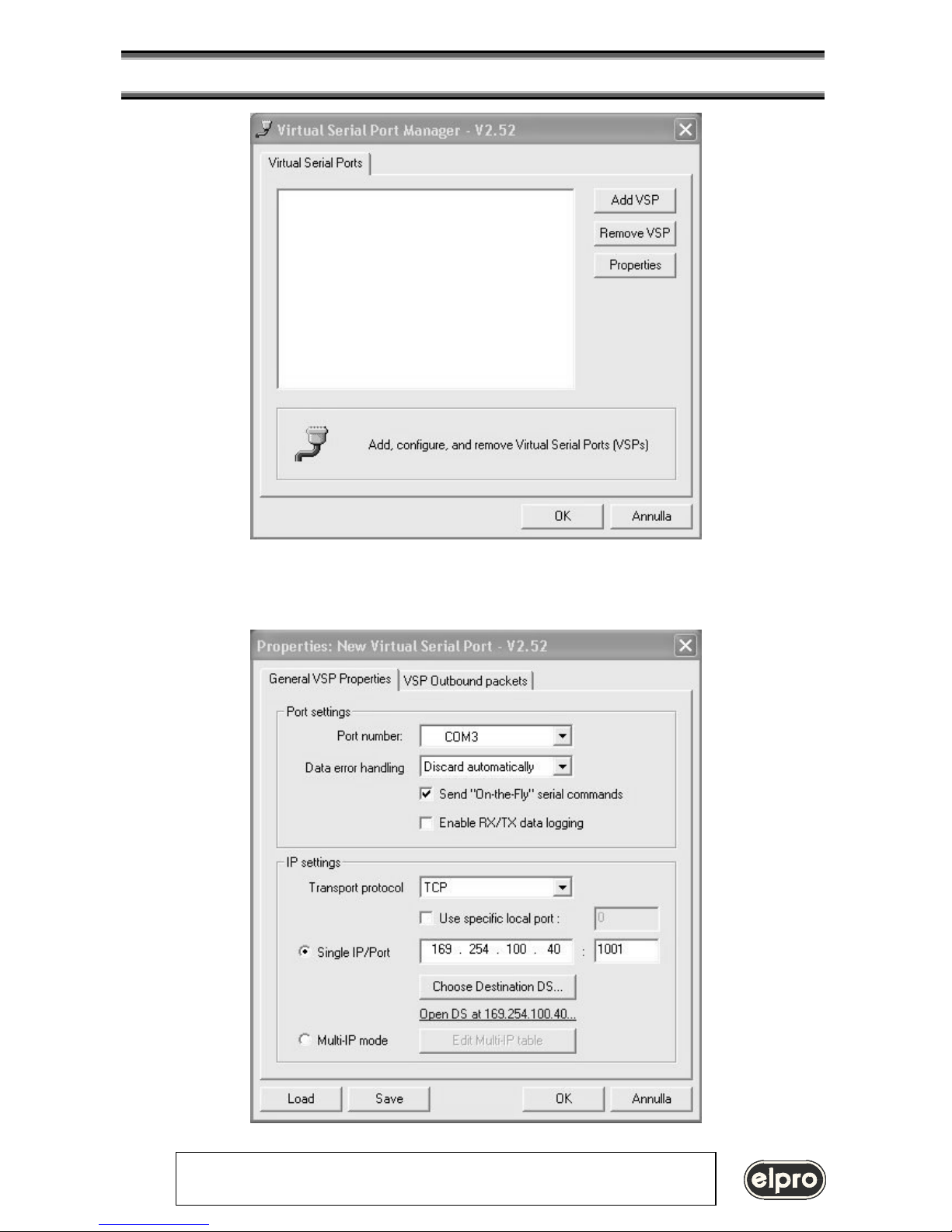
Creation of a Virtual COM.
Execute the Virtual Serial Port Manager function to create a virtual COM on the PC
Page 16
LIN101
RS232 / LAN INTERFACE
ELPRO Video Labs s.r.l.
Via della Praia 4/a FERRIERA di BUTTIGLIERA ALTA (TO) - ITALY
Tel. +39 0119348778 - FAX +39 0119348779
16
This tool links a virtual COM with the defined IP-address
Page 17
LIN101
RS232 / LAN INTERFACE
ELPRO Video Labs s.r.l.
Via della Praia 4/a FERRIERA di BUTTIGLIERA ALTA (TO) - ITALY
Tel. +39 0119348778 - FAX +39 0119348779
17
The existing PC software then can interface COM3: as an installed hardware communication port.
Note: after the LIN101 configured it is possible to test it by PING command. In DOS environment use the following
ping 169.254.100.40
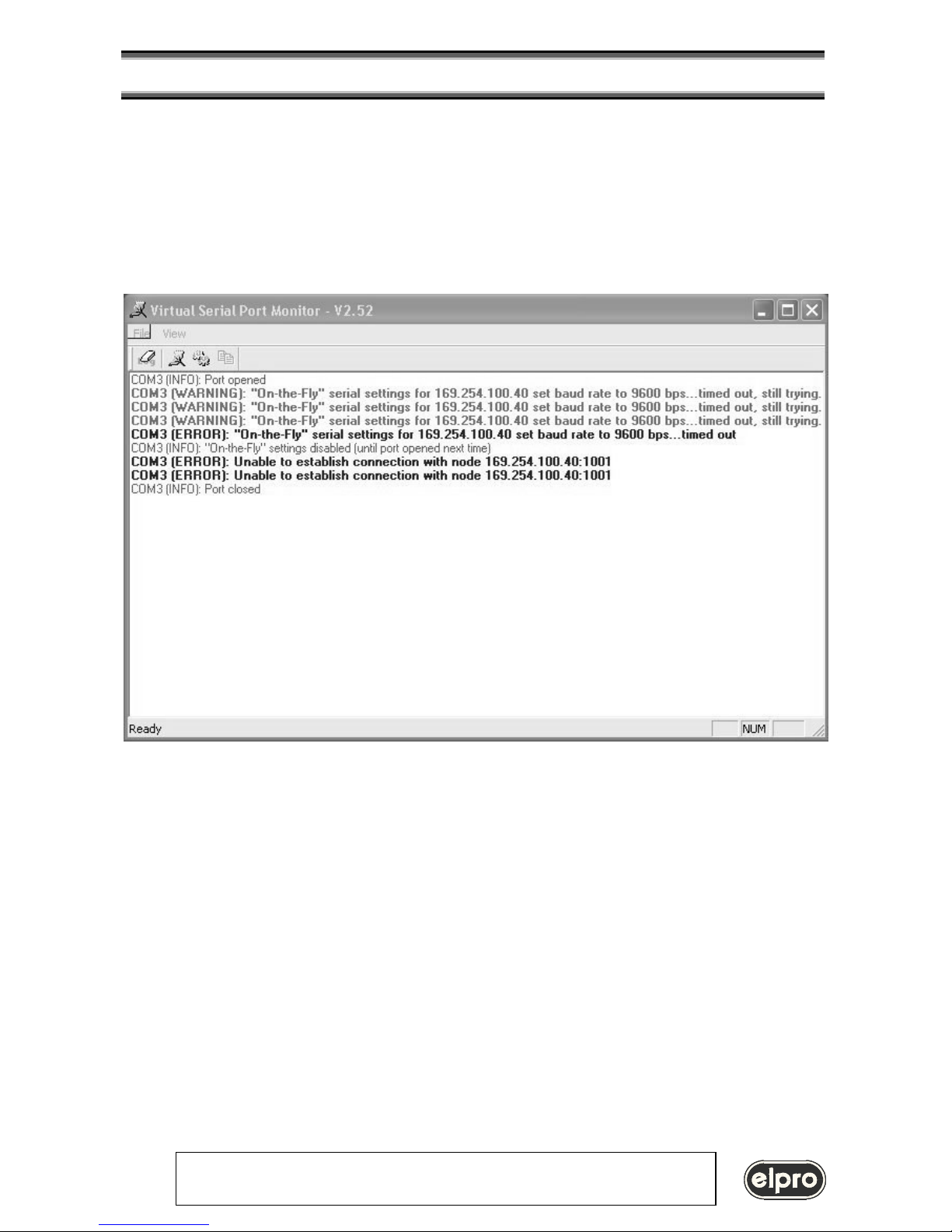
5.3 Port Monitor Log
The VSP Monitor Log logs all VSP messages (error, warning, info) about operations regarding virtual COMs
Page 18
LIN101
RS232 / LAN INTERFACE
ELPRO Video Labs s.r.l.
Via della Praia 4/a FERRIERA di BUTTIGLIERA ALTA (TO) - ITALY
Tel. +39 0119348778 - FAX +39 0119348779
18
6. Connections
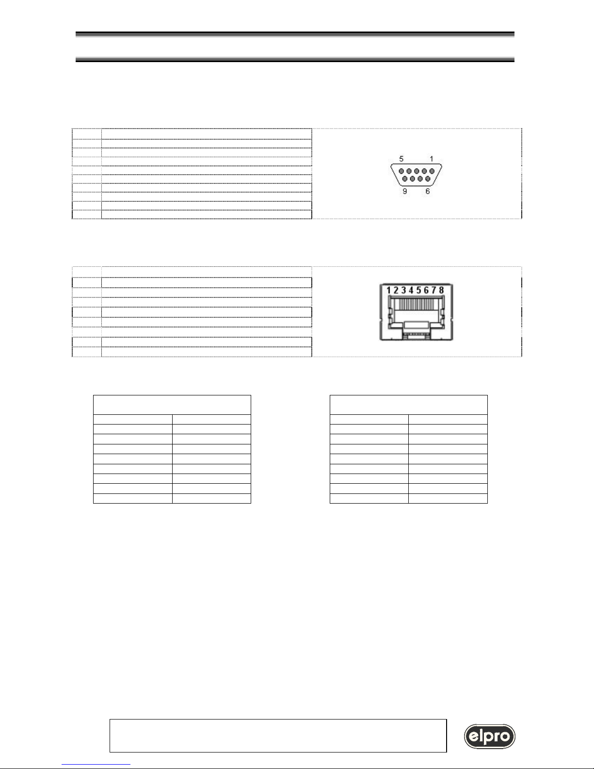
I/O connectors pin assignment
Serial port: 9 pin fem.
Pin Signal
1 no connection
2 Rx
3 Tx
4 internally connected to pin 4
5 GND
6 internally connected to pin 6
7 RTS
8 CTS
9 no connection
Ethernet port 10BaseT: RJ45 8 pin fem.
Pin Signal
1 Tx+
2 Tx3 Rx+
4
no connection
5
no connection
6 Rx7
no connection
8
no connection
Ethernet wiring
Wiring between LIN101 and HUB
Wiring between two LIN101
Side A Side B
Side A Side B
1
1
1
3
2
2
2
6
3
3
3
1
4 4 4 4
5 5
5
5
6
6
6
2
7 7 7 7
8 8 8 8
Note: wire 1 and 2 twisted pair
wire 3 and 6 twisted pair
Page 19

LIN101
RS232 / LAN INTERFACE
ELPRO Video Labs s.r.l.
Via della Praia 4/a FERRIERA di BUTTIGLIERA ALTA (TO) - ITALY
Tel. +39 0119348778 - FAX +39 0119348779
19
7. Technical specifications
Ethernet Interface : 10 Base T
Network Cable : CAT5
Network Protocols : UDP, TCP, ICMP, ARP
Buffer Size : 2 independent 255 bytes
Serial Interface : RS232
Signals : RxD TxD, RTS, CTS
Serial Speed : from 150 bit/sec to 115200 bit/sec
Power : 9 Vac (external power suply)
Consumption : 3 VA
Size (WXDXH) : 94.5 x 71.5 x 25 mm
Weight :
Temperature Range : 0 ÷ 45°C
Security : EN 60065
EMC : EN 55103-1, EN 55103-2, EN 50081 part 1 e 50082 part 1
 Loading...