

ELPRO EL-MX-B004 Owner's Manual
1
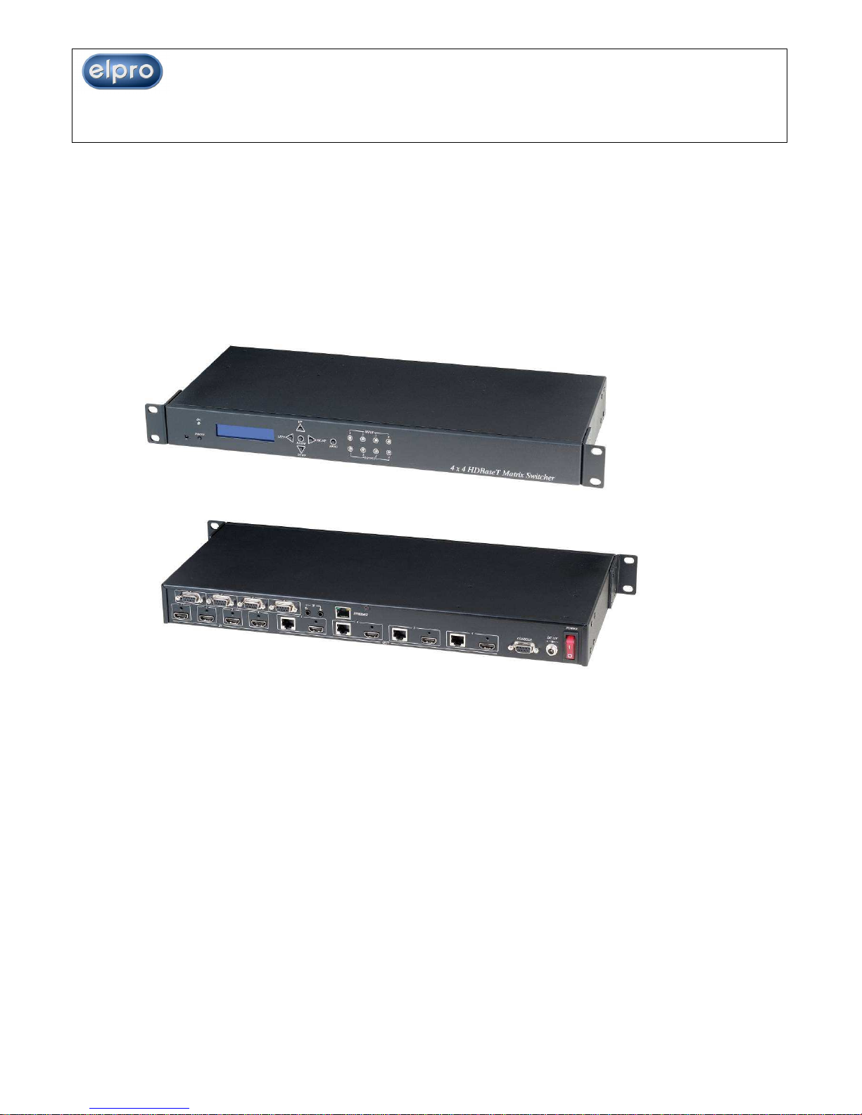
ITEM NO.: EL-MX-B004 4 x 4 HDMI + HDBaseT Matrix Switcher
With the latest and reliable HDBaseT technology this matrix extends HDMI sources up to
100M at 1080p or 1920x1200. HDMI outputs are provided as well.
It provides 3D support, and is 1 RU Rack mountable for professional installations.
In addition, the EL-MX-B004 can be controlled by GUI Ethernet, Android and iOS App
Control, IR remote control, RS-232, Telnet and by the front panel
EL-MX-B004 4 x 4 HDMI (HDBaseT) Matrix Switcher
4 x HDMI inputs, 4 x HDMI Outputs Matrix switcher
Dual Output: local HDMI port and remote RJ45 HDBaseT™
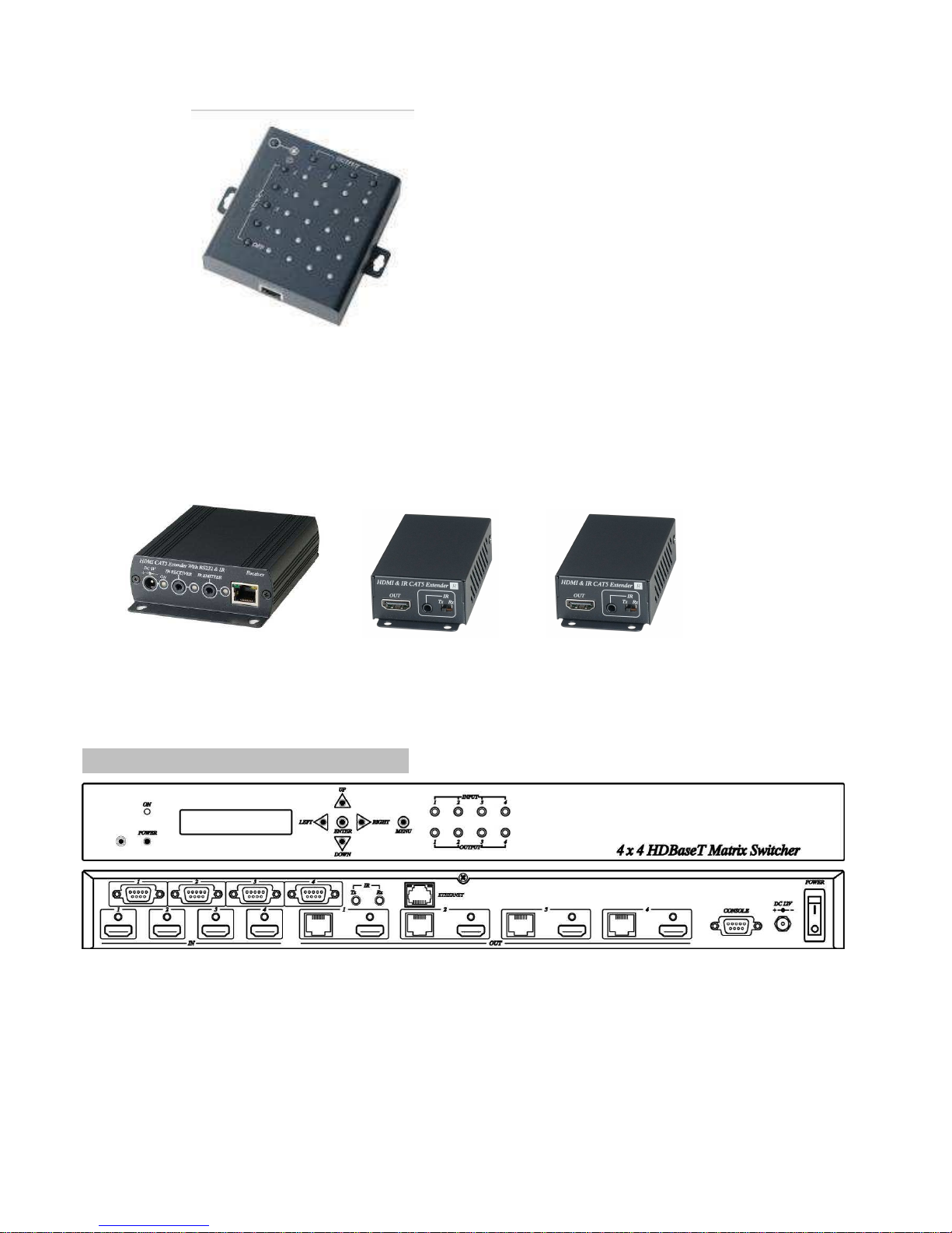
Works with HE02ER, HE02R receiver at each monitor up to 100 meters over
CAT5e/6.
Works with HE02EIR receiver at each monitor up to 70 meters over CAT6a cable.
Three control option: Front panel button, IR remote control, RS232 through remote
PC.
Support local/remote IR control to select input/output.
Built in RS232 console port to select input/output.
Built 1 in 4 out IR distributor function, allow the EL-MX-B004 control each
monitor and also the IR remote control can be used to select the input
source from the monitor side.
Built in Ethernet GUI Control, Android and iOS App Control.
Uncompressed high definition video 1080p@60Hz 12 bit and 3D capable
HDMI 1.4 video features supported, HDCP compliant.
Built in 4 channel IR and RS232 extender (work with Receiver: HE02EIR, HE02ER)
HDMI (HDBaseT) Matrix Switcher Series
February 3rd., 2016 Firm. Version 1.18
2
Input/Output status could be displayed at front panel LCM & LED.
Optional Model:
RC04 : 4 x 4 Keypad remote control (select EL-MX-B004 input/output)
Optional CAT5E/CAT6 Receiver Model:
HE02ER: 100m HDMI Receiver
HE02R : 100m HDMI, bidirectional IR and RS232 Receiver
HE02EIR: 70m HDMI and IR mono directional
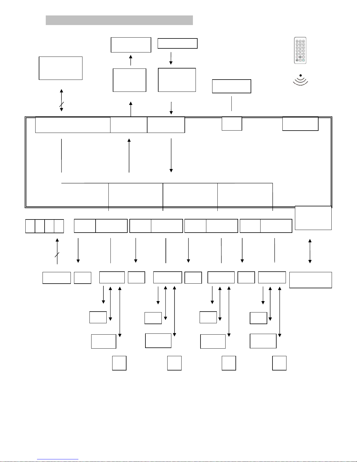
1.0 EL-MX-B004 Panel View:
3
2.0 EL-MX-B004 Connection View:
4
4
HDMI IN OUTPUT 1 OUTPUT 2 OUTPUT 3 OUTPUT 4
4
100M
100M100M
100M 100M 100M 100M
100M 100M 100M 100M 100M 100M
100M 100M 100M
* Under dual Output connection: Once you link both HDMI and HDBaseT connection,
the output effected is the HDMI port only. For HDBaseT active output, you must
disconnect the HDMI output link.
SOURCE
1
RS232 *4
HDMI HDBaseT
CONSOLE
RS232
TV
TV
HE02
R HE02R
HE02R
HE02R
RS232 Control
IR TX
IR RX
IR Emitter Cable
(IR-CT01)
RS232
IR Remote Control
IR Receiver
IR Receiver Cable
(IR-CR01)
PC、KEYPAD
BD PLAYER
HDMI
HDMI
HDMI
HDBaseT
HDBaseT
HDBaseT
2 3 4
TV
TV
TV
TV
TV
TV
IR
RS232
RS232
RS232
IR IR IR
IR01
RJ45
ETHERNET

4
3.0 Keypad and Leds
3.1 Back Panel Switch:
POWER Light on Power on
Light off Power off
3.2 Front LED Indication:
ON BLUE Power on
RED Standby
LED off Power Off
INPUT 1, 2, 3, 4 BLUE Presence signal indication
LED off No signal incoming
OUTPUT 1, 2, 3, 4 BLUE HDMI output indications
RED HDBaseT output indication
LED off Output unlink
Front Button Function:
Power Power on/standby
UP up
DOWN down
LEFT left
RIGHT right
ENTER select confirm key
MENU back to main menu
*When the sub-menu setting changed, press the ENTER key to complete the setting. If
ENTER key is not pressed, then the setting will be failed.
Warning: When the matrrix is in standby mode, the IR Remote Control only commands
POWER on/off.

5
3.3 LCM Panel Function:
Power on Main Screen
When the power is on and the main screen appears
Channel Setting on Main Screen
The Matrix will jump to channel setting screen after 10 seconds, press the MENU key to
enter the main
Main MENU Option:
*1. SWITCH
*2. RS-232
*3. IR TX
*4. IR RX
*5. HDB…T IR ID
*6. MATRIX IR ID
*7. ETHERNET
*8. EDID
*9. VERSION
*10. KEYLOCK
*11. SCENEE
Operation:
Press UP or DOWN key to move * to select an item for setting and press ENTER key
to enter into subpage.
In MENU you could use key 1~11 of IR remote control to select the functions.
When the selected sub-page setting is completed, press the MENU button to return
to the main page
4 X 4 HDMI MATRIX
OUT 1 2 3 4
IN 1 2 3 4
6
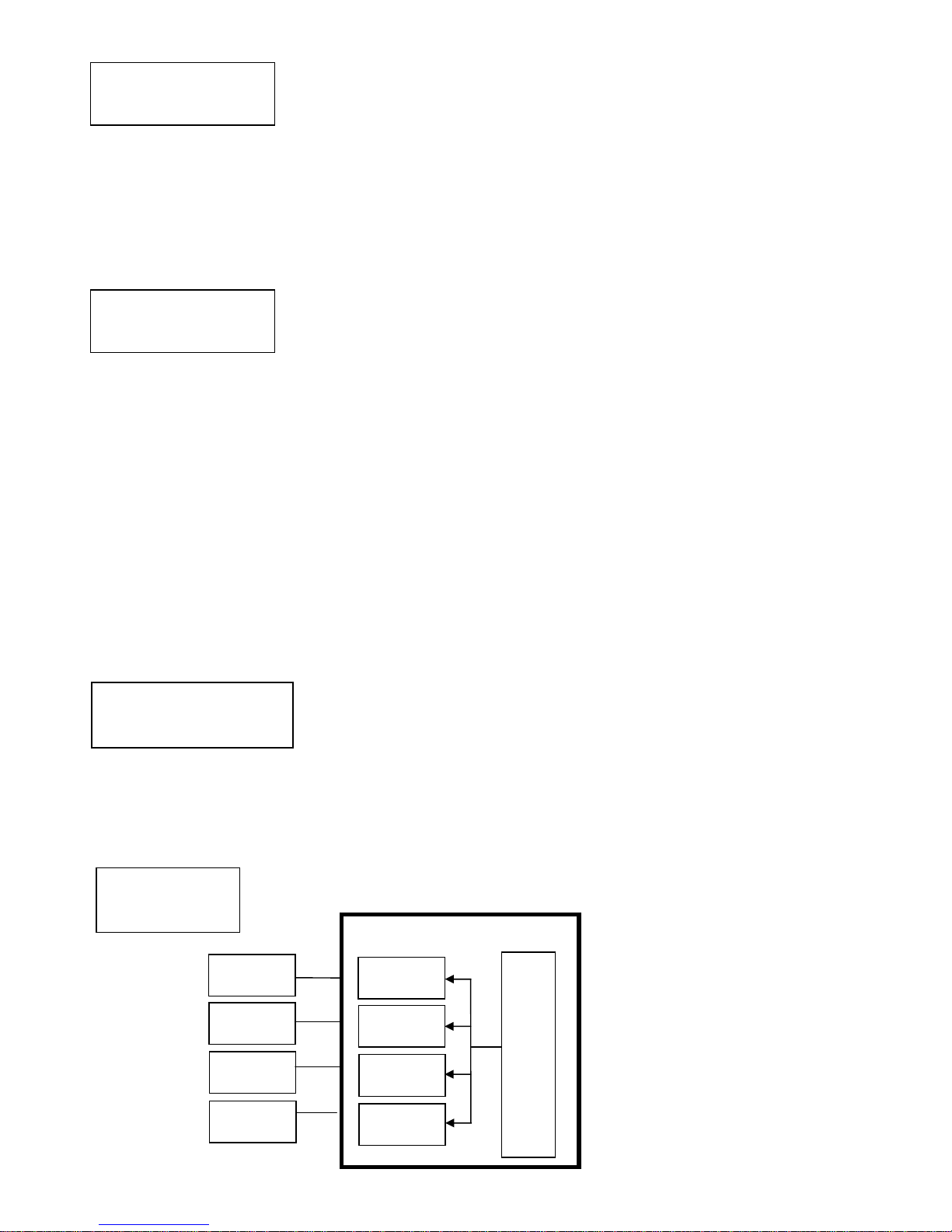
4.0 LCM Main MENU Function Operation:
4.1 SWITCH::::(Default: 1 2 3 4)
OUTPUT 1 2 3 4
INPUT 1 2 3 4
This function is used to switch the input/output port. Enter the SWITCH menu. Press
the ENTER key, then the LCM second line INPUT will flash. Press LEFT or RIGHT button
to select the output to be modified. Then press UP or Down button to select the input
port. After that, press ENTER to confirm setting.
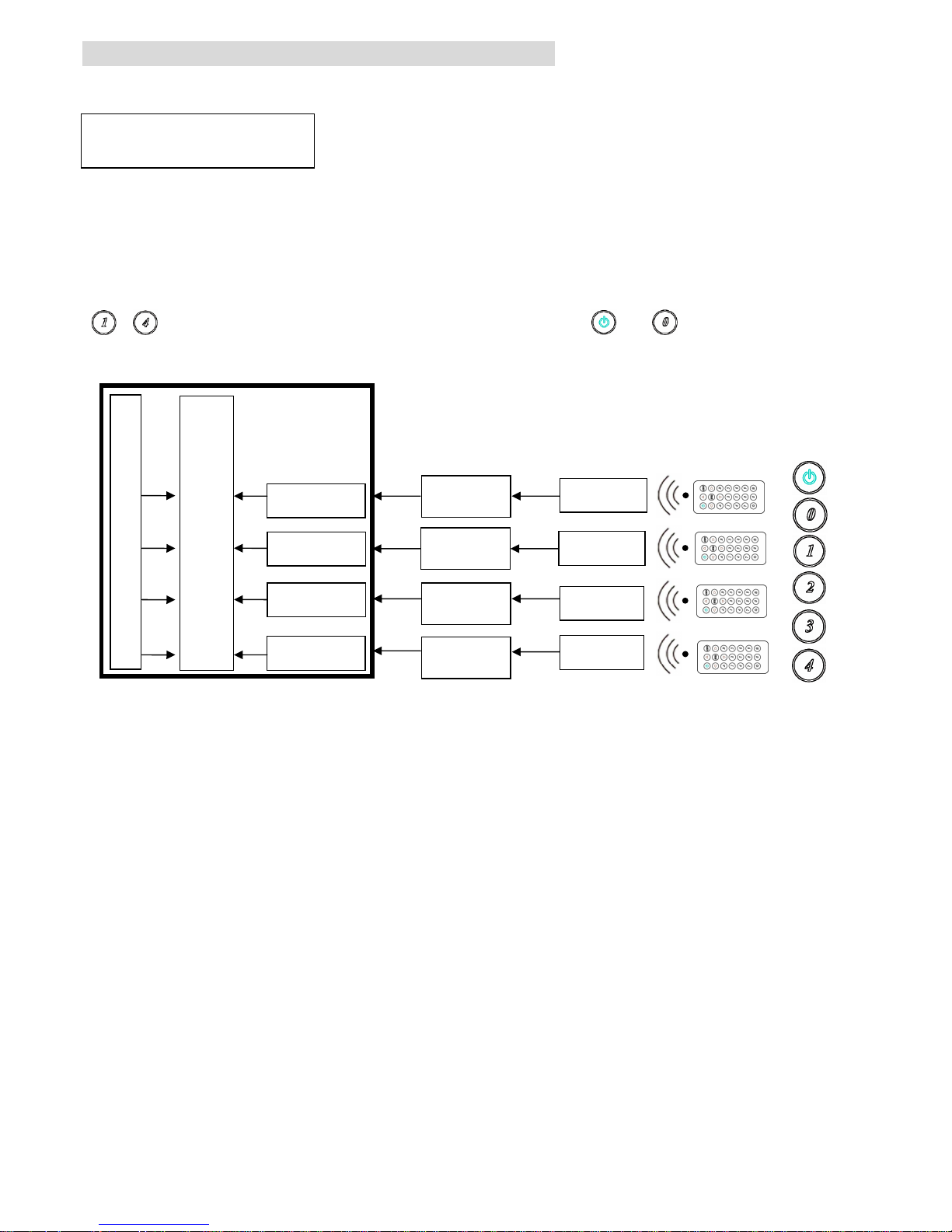
At HDBaseT remote port you could use IR01 remote control to do a quick input selection
~ represent select HDMI input ports 1~4. Press or to turn off the video
output. (See cap. 4.5 HDBaseT IR ID)
EL
ELEL
EL----MX
MXMX
MX----B004
B004B004
B004
HE02R - 1
HE02R - 2
HE02R - 4
HE02R - 3
IR-CR01
IR-CR01
IR-CR0
1
IR-CR0
1
HDBaseT - 1
HDBaseT - 2
HDBaseT - 3
HDBaseT - 4
OUTPUT 1 2 3 4
INPUT 1 2 3 4
HDMI INPUT 1 2 3 4
IR01
7
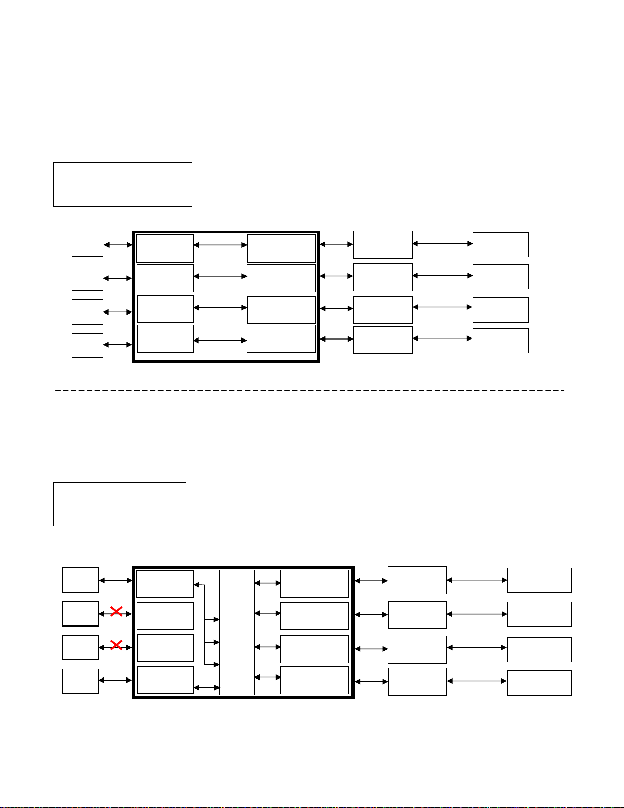
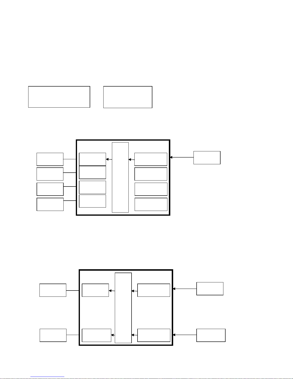
4.2 RS-232::::(Default: FIX MODE)
HDBaseT RS-232 extender function works in two mode. Enter RS-232 MENU, press
ENTER. The * will flash, then press UP or DOWN button to select FIX MODE or
MATRIX MODE. Press ENTER key to confirm setting.
FIX
MODE is one to one transmission, RS-232 port 1 only work with HDBaseT port 1,
RS-232 port 2 only work with HDBaseT port 2, and so on…
EL-MX-B004
RS-232 SETTING : FIX MODE
RS-232
MATRIX
MODE is based on the Status of the Matrix. The RS-232
transmission will follow the HDMI switching. In the example below, RS-232 port 1
work with HDBaseT port 1, 2 and 3. RS-232 port 4 works with HDBaseT port 4
EL-MX-B004
RS-232 SETTING : MATRIX MODE
HE02R - 1
HE02R - 2
HE02R - 4
HE02R - 3
HDBaseT - 1
Projector
RS232 - 4
RS232 - 3
RS232 - 2
RS232 - 1
HDBaseT - 2
HDBaseT - 3
HDBaseT - 4
Projector
Projector
Projector
PC
PC
PC
PC
RS232 Cable
RS232 Cable
RS232 Cable
RS232 Cable
HDMI - 4
RS232 - 4
HDMI - 3
RS232 - 3
HDMI - 2
RS232 - 2
HDMI - 1
RS232 - 1
HDBaseT - 1
HDBaseT - 2
HDBaseT - 3
HDBaseT - 4
Projector
Connect To PC 1
Projector
Connect To PC 1
Projector
Connect To PC 1
Projector
Connect To PC 4
PC 1
PC 2
PC 3
PC 4
HE02R - 1
HE02R - 2
HE02R - 4
HE02R - 3
RS232 Cable
RS232 Cable
RS232 Cable
RS232 Cable
*
FIX MODE
MATRIX MODE
MATRIX MODE
*
MATRIX MODE
OUTPUT 1 2 3 4
INPUT 1 1 1 4
Connect To
HDBaseT - 1
HDBaseT - 2
HDBaseT - 3
Connect To
HDBaseT - 4
8
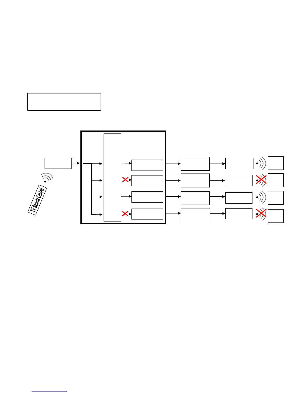
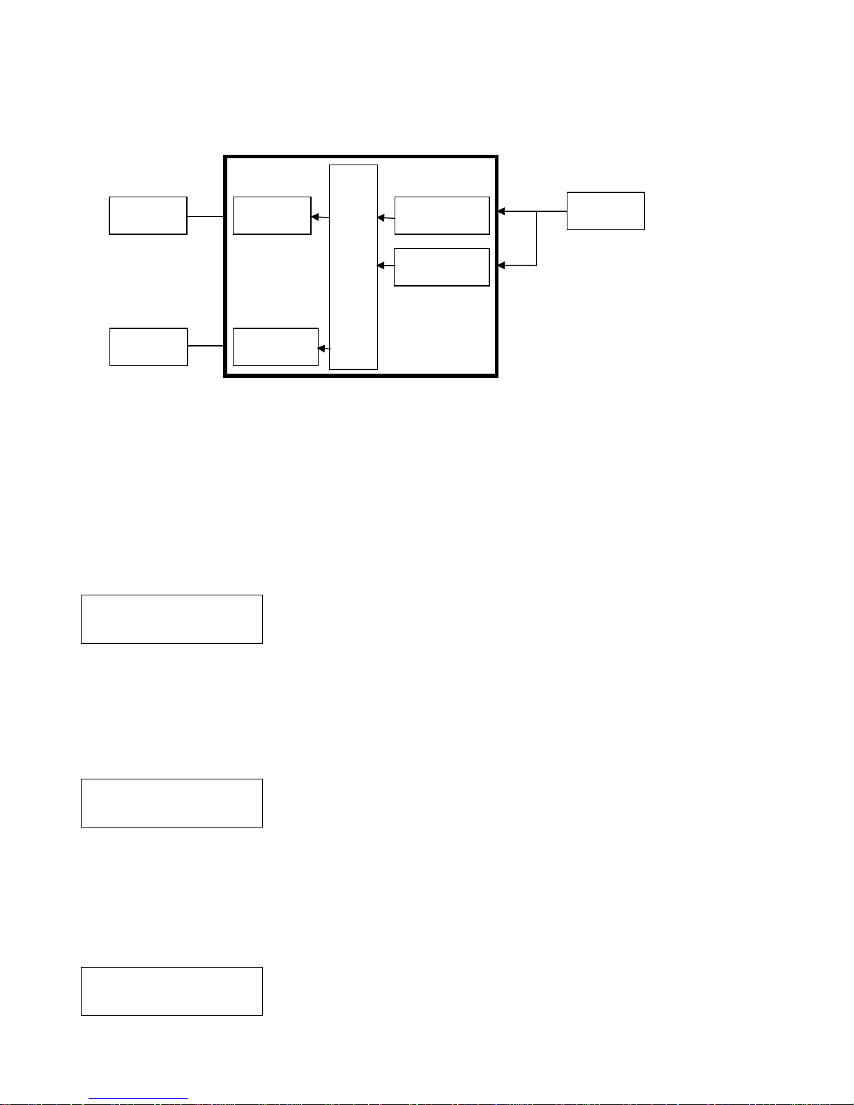
4.3 IR TX
(From matrix to remote locations)
: (Default IR TX: O O O O)
This function setup the IR signal whether from MATRIX, by IR Rx input jack, is sent to
HDBaseT ports. Setting O the transmission is enabled, setting X transmission is off.
This is the typical application when the user wants to control from the matrix side the
remote destination like a TV.
After entering IR TX menu, press ENTER. Then LCM second line of text will flash. Press
RIGHT or LEFT button to select the IR TX output to be modified Press Press UP or DOWN
button to select O or X. Then press ENTER to confirm setting.
HDBaseT 1 2 3 4
IR RX O X O X
O : on X : off
EL
ELEL
EL----MX
MXMX
MX----B004
B004B004
B004
IR-CR01
HE02R - 1
HE02R - 2
HE02R - 4
HE02R - 3
IR-CT01
IR-CT01
IR-CT01
IR-CT01
TV
TV
TV
TV
HDBaseT - 1
HDBaseT - 2
HDBaseT - 3
HDBaseT - 4
HDBaseT 1 2 3 4
IR TX O X O X
9
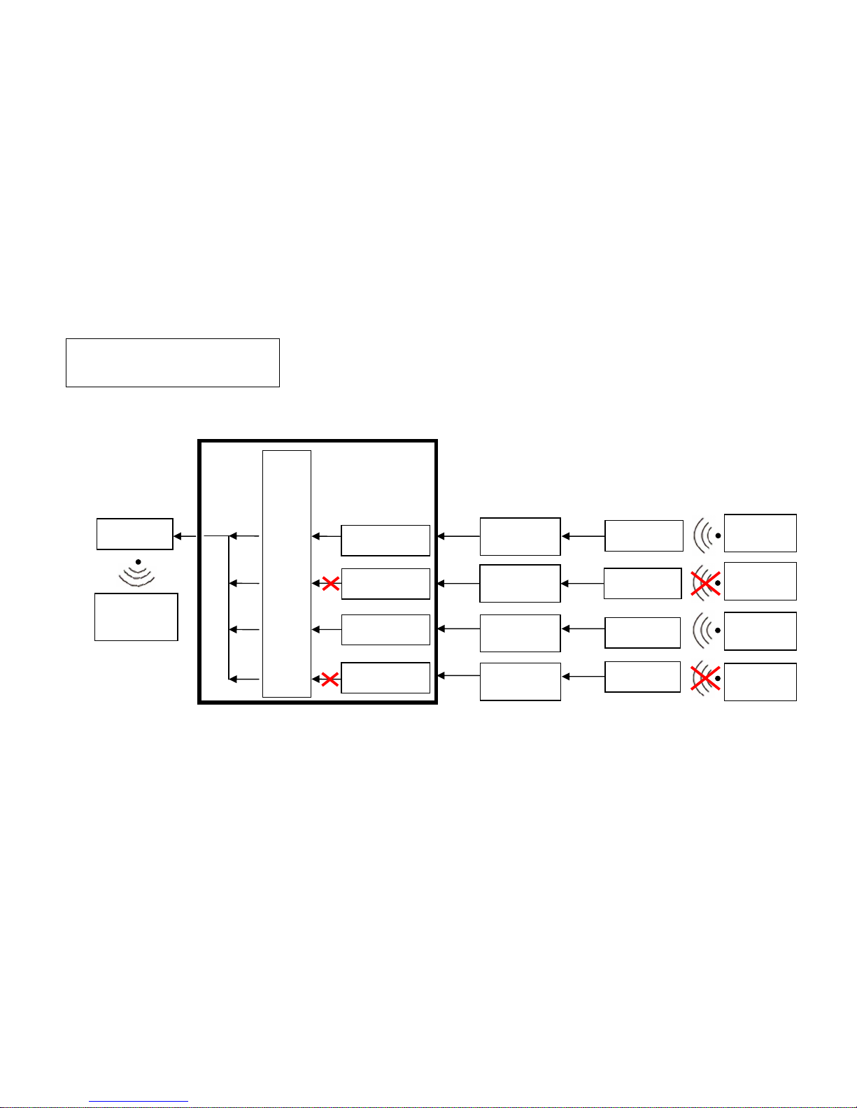
4.4 IR RX::::
(From remote locations to matrix)
(Default IR RX: O O O O)
This function setup the IR signal whether from HDBaseT location is sent to MATRIX to
control local device through the IR Tx output jack. Setting O the transmission is enabled,
setting X transmission is off.
This is a typical application when the user wants to control from the remote location a
source like a DVD player.
After entering IR RX menu, press ENTER. Then LCM second line of text will flash. Press
RIGHT or LEFT button to select the IR RX input to be modified. Press UP or DOWN
button to select O or X. Then press ENTER to confirm setting.
HDBaseT 1 2 3 4
IR TX O X O X
O : on X : off
EL
ELEL
EL----MX
MXMX
MX----B004
B004B004
B004
IR-CT01
HE02R - 1
HE02R - 2
HE02R - 4
HE02R - 3
IR-CR01
IR-CR01
IR-CR01
IR-CR01
Player
Remote Control
Player
Remote Control
Player
Remote Control
Player
Remote Control
HDBaseT - 1
HDBaseT - 2
HDBaseT - 3
HDBaseT - 4
HDBaseT 1 2 3 4
IR RX O X O X
Player
10
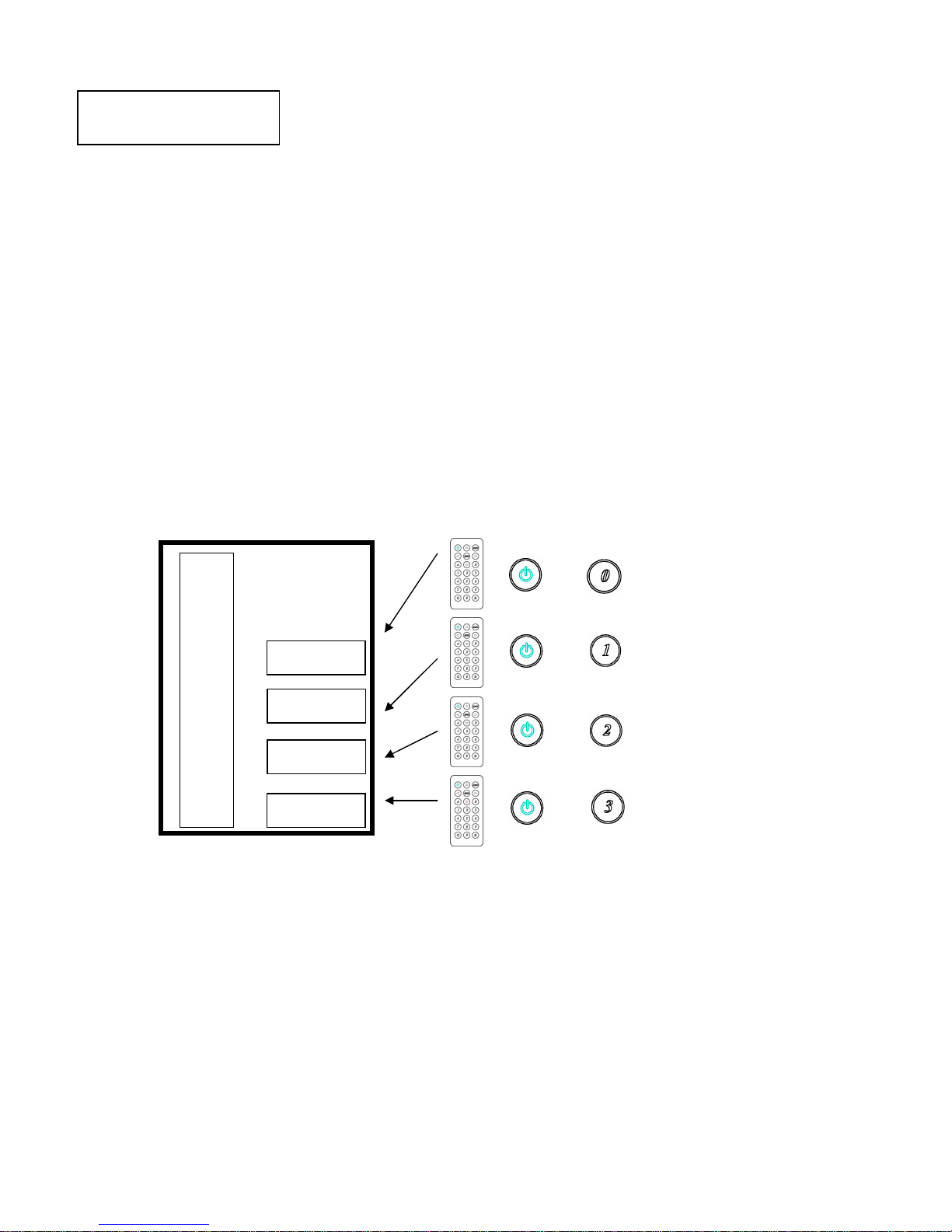
4.5 HDBaseT IR ID::::(Default IR ID: 0 1 2 3)
This function is set to have different ID in order to avoid HDBaseT remote control IR01
conflicts with other devices remote control.
After entering HDBaseT IR ID menu, press ENTER. Then LCM second line of text will
flash. Press RIGHT or LEFT button to select the IR ID input to be modified. Press UP or
DOWN button to select the ID. Then press ENTER to confirm setting.
When you finish the HDBaseT IR ID setting, the HDBaseT remote controls IR01 must
also be setted with the same ID in order to perform the right operations. (See 5.2)
Remote IR ID setting mode: Press and hold the POWER button, then press the
number button which can be set from 0 to 9, total 10 groups. (See 5.2)
These settings on IR01 remote control have to be done the first time you use the IR01
or when you change the batteries.
HDB
HDBHDB
HDB
...
......
...
T 1 2 3 4
T 1 2 3 4T 1 2 3 4
T 1 2 3 4
IR ID
IR ID IR ID
IR ID 0000
1111
2222
3333
EL
ELEL
EL----MX
MXMX
MX----B004
B004B004
B004
HDBaseT - 1
HDBaseT - 2
HDBaseT - 3
HDBaseT - 4
HDB...T 1 2 3 4
IR ID 0 1 2 3
IR01
11
4.6 MATRIX IR ID::::(Default IR ID: 4)
This function must be set to match the Matrix remote control IR01 with the matrix itself.
Conflicts with other devices remote control is therefore avoided.
After entering MATRIX IR ID menu, press ENTER, the LCM LINE 1 number will flash.
Then Press UP or DOWN button to select the number, and then press ENTER to confirm.
When finish MATRIX IR ID setting, MATRIX remote control IR01 must also set the same
ID in order to operation in normal.
When you finish the MATRIX IR ID setting, the remote control IR01 that will control
locally the matrix, must be setted with the same ID in order to perform the right
operations. (See 5.1)
Remote IR ID setting mode: Press and hold the POWER button, then press the
number button which can be set from 0 to 9, total 10 groups. (See 5.1)
These settings on IR01 remote control have to be done the first time you use the IR01
or when you change the batteries.
MATRIX IR ID 4
EL
ELEL
EL----MX
MXMX
MX----B004
B004B004
B004
MATRIX IR ID 4
IR01

12
4.7 Ethernet
* IP Address
Subnet Mask
Gateway
DHCP Client
Media Type
MAC Filter
IP Address: (Default: 192.168.0.200)
This function can be setup MATRIX host intranet ”IP Address”, press the ENTER, the
left-most number of second row will flash, then press the UP or DOWN button to change
the numbers, , press LEFT or RIGHT to move to another location, the move to a position
number will flash, press ENTER to complete the setting.
Subnet Mask: (Default 255.255.255.0)
This function can be setup MATRIX host intranet “Subnet Mask”, press the ENTER, the
left-most number of second row will flash, then press the UP or DOWN button to change
the numbers Press the ENTER, , press LEFT or RIGHT to move to another location, the
move to a position number will flash, press ENTER to complete the setting.
Gateway: (Default 192.168.0.1)
This function can be setup MATRIX host intranet “Gateway”, press the ENTER, the
left-most number of second row will flash, then press the UP or DOWN button to change
the numbers Press the ENTER, , press LEFT or RIGHT to move to another location, the
move to a position number will flash, press ENTER to complete the setting.
Warning
Setting IP Address, Subnet Mask and Gateway can be done as well
by RS232 as described at chapter 6.3
At the first setting, it’s recommended to use
the software “HS04M_Browser for LAN Modules.zip” application
as described in the chapter 10
IP Address
192.168. 0.200
Subnet Mask
255.255.255.000
Gateway
192.168. 0. 1
13
DHCP Client: (Default Disable)
When DHCP Clients setup at “Enable”, the MATRIX host will automatically get IP Address,
Subnet Mask, Gateway, if setup at “Disable”, the MATRIX Host IP Address need go
through “ ETHERNET” menu to set IP Address, Subnet Mask, Gateway, to press the ENTER,
the second row will flash, then press the UP or DOWN to select DISABLE, ENABLE, then
press ENTER to complete the setting.
Media Type: (Default 100M)
This function can be setup MATRIX host intranet “Media Type, press the ENTER, the
second row will flash, then press the UP or DOWN button to select 10M, 100M, AUTO,
press ENTER to complete the setting.
MAC Filter : (Default Disable)
MAC Filter can be setup with registered MAC Address in order to connect the MATRIX host
Web UI, MAC Address required by the Web page to fill in, this function can only be setup
at “DISABLE”, “ENABLE”, then to press the ENTER, the second row will flash, then press
the UP or DOWN to select DISABLE, ENABLE, then press ENTER to complete the setting.
4.8 EDID: (Default: Build-in Mode, LPCM-2CH)
The Matrix provides four default EDID modes:” BUILD-IN MODE”, “COPY MODE”, “I.
EDID MODE” and “PC EDID MODE”.
4.8.1 BUILD-IN MODE::::
This mode supports video resolution 480p, 720p, 1080i / p at 24/50/60Hz and supports
LPCM 2 channel audio and 5.1 channel. After enter BUILD-IN MODE menu, press UP or
DOWN key to select LPCM-2CH or LPCM-5.1CH, then press ENTER to confirm setting.
BUILD-IN MODE
COPY MODE
LPCM-2CH
LPCM-5.1CH
EL
ELEL
EL----MX
MXMX
MX----B004
B004B004
B004
LPCM-2CH
LPCM-5.1CH
HDMI – 4
EDID
HDMI – 3
EDID
HDMI – 2
EDID
HDMI – 1
EDID
Player - 4
Player - 3
Player - 2
Player - 1
DHCP Client
Disable
Media Type
100M
14
4.8.2 COPY MODE::::
To fully support the TV resolution and audio mode, the matrix provides “copy mode” to
copy TV EDID for input source reference. When use the copy mode, is recommended to
copy the lowest resolution TV EDID. Otherwise it may cause no picture display if the TV
resolution is not able to support higher resolution.
After entering COPY MODE menu, press UP or DOWN button to select the OUTPUT (1 to 4)
and press ENTER, then press UP or DOWN button to select the INPUT (1 to 4 or ALL) and
press ENTER to confirm. Only connected output will be shown in OUTPUT list.
Warning: Copy the EDID of the lowest resolution monitor to ALL sources is the shortest
way to ensure that all monitors will show the image.
4.8.3 I. EDID MODE
In this mode, the MATRIX checks all the connected monitors and copies the EDID of the
monitor that presents the lowest resolution. This EDID is then transmitted to all
sources. E.g., if there is a monitor 1080p and a monitor 720p, the matrix transmits to the
sources the EDID of the 720p monitor.
. .
. .
. .
. .
. .
EL
ELEL
EL----MX
MXMX
MX----B004
B004B004
B004
HDMI - OUT 4
HDMI - OUT 3
HDMI - OUT 2
HDMI - OUT 1
Player - 4
Player - 3
Player - 2
Player - 1
HDMI - IN4
LPCM-2CH
HDMI - IN3
LPCM-2CH
HDMI - IN2
LPCM-2CH
HDMI - IN1
TV1 EDID
From OUTPUT : 1
To INPUT : 1
TV1 EDID
COPY MODE
From OUTPUT : 1
COPY MODE
To INPUT : 1
EL
ELEL
EL----MX
MXMX
MX----B004
B004B004
B004
.
.
.
.
HDMI – IN 4
All EDID
HDMI - IN1
All EDID
I..EDID MODE
TV1 EDID
Player - 4
Player - 1
HDMI - OUT 4
HDMI - OUT 1
TV4 EDID
15
4.8.4 PC EDID MODE
In this mode you could upload EDID file (.dat or .bin format) from RS232 or RJ45 port to
the MATRIX. Please refer to file “EL-MX-B004_EDID Loader Instruction V1.2.0” that you
can download for our web site. Software “160201 EDID Loader setup V1.2.0.exe” is
provided in the same web page.
.
.
.
.
.
4.9 VERSION :
Display EL-MX-B004 Matrix firmware version
4.10 KEYLOCK :
Panel button/IR remote lock function is to avoid any wrong button press. Under keylock
mode press “POWER + MENU” to unlock
4.11 SCENE:
SCENE function provide 10 sets of channel setting to fast reload for different application.
LOAD (RECALL)
Reload saved scene, press UP or DOWN to select the number of setting and ENTER to
load.
At main screen you could use IR01 remote button A for quick load function,
button 1~0 to select the number of scene to load.
SAVE
Save current channel setting, press UP or DOWN to select the number and ENTER to
save.
At main screen you could use IR01 remote button B for quick save function,
button 1~0 to select the number of scene to save.
LOAD
SAVE
EL
ELEL
EL----MX
MXMX
MX----B004
B004B004
B004
HDMI – IN4
All EDID
HDMI - IN1
All EDID
PC
EDID
MODE
PC
Player - 4
Player - 1
RJ45 Port
RS232 Port
LOAD 1
1 2 3 4 5 6 7 8 9
SAVE 1
1 2 3 4 5 6 7 8 9

16
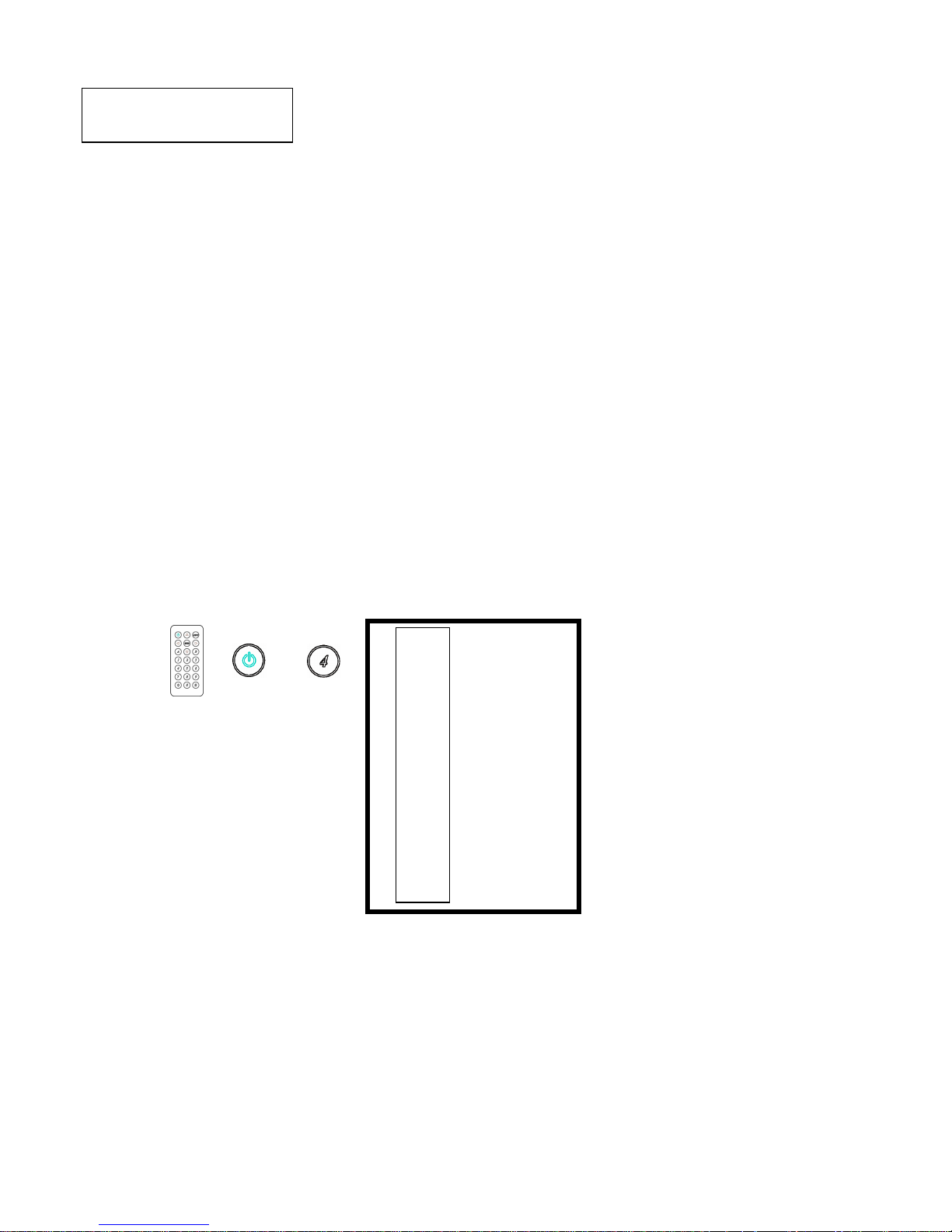
5.0 Remote Control Function ( IR01):
5.1 To command the matrix locally, setup the remote control IR01 ID with the same code
of the Matrix (see 4.6). The default code is 4. (Power+4)
5.2 To command from remote HDBaseT output which input port must be routed on the
output, setup the remote control IR01 according to chapter 4.5
-Power+0 enable to work on Output 1
-Power+1 enable to work on Output 2
-Power+2 enable to work on Output 3
-Power+3 enable to work on Output 4
5.3 Warning: These settings have to be done the first time you use the IR01 or when you
change the batteries.
IR ID setup : press and hold POWER button , then press Number key
Remote control button define :
Symbol Local Side Remote Side
Power ON/Standby(same as Matrix) turn off output
LEFT left (same as Matrix) no function
RIGHT right (same as Matrix) no function
UP up (same as Matrix) no function
DOWN down (same as Matrix) no function
ENTER confirm (same as Matrix) no function
MENU menu (same as Matrix) no function
A LOAD no function
B SAVE no function
Quick key1 select input 1
Quick key2 select input 2
Quick key3 select input 3
Quick key4 select input 4
 Loading...