

ELPRO ECOLOG-PRO Base Operation Manual

ECOLOG-PRO Base
Operation Manual

Document: EP6002Eb
2 - EN
Table of Contents
1 ECOLOG-PRO Base .................................................................................. 4
2 Initial Startup.................................................................................................. 6
2.1 ECOLOG-PRO Base ....................................................................................... 6
2.2 LAN Connection............................................................................................... 7
2.3 WLAN Connection ........................................................................................... 7
2.4 Initialization ...................................................................................................... 8
3 ECOLOG-PRO Base Maintenance ................................................ 12
3.1 Region............................................................................................................ 12
3.2 Network.......................................................................................................... 13
3.3 Database........................................................................................................ 14
3.4 Update ........................................................................................................... 15
3.5 System ........................................................................................................... 15
3.6 WebAccess .................................................................................................... 16
3.7 Example of a Configuration Report................................................................ 17
4 Operating Modes ....................................................................................... 18
4.1 Connection via SWITCH (operated autonomously) ....................................... 18
4.2 Integration in Customer Network ................................................................... 19
5 Power Supply Unit.................................................................................... 20
6 Recovery.......................................................................................................... 21
7 Scope of Supply......................................................................................... 22
8 Revision History......................................................................................... 23
Document: EP6002Eb
3 - EN
Symbols and Description Codes Used
Information
IMPORTANT INFORMATION AND WARNINGS
DELETE Windows functions, for example Delete
<xxxxxxxxx> Syntax for placeholders.
Placeholders are written in < > brackets.
Reference to related chapter or document.
Presentation only refers to part of the
user interface.
Ethernet cable
WLAN / WiFi, radio connection between: Base, WLAN modules and
customer network.
Radio connection between radio modules
In the interests of our customers, we reserve the right to make any changes
resulting from technical advances. For this reason, diagrams, descriptions, and
the scope of delivery are subject to change without notice. This manual is valid as
from Version 2017.
CHANGES OR MODIFICATIONS MADE TO THIS EQUIPMENT MAY INVALIDATE THE
ETSI /
FCC AUTHORIZATION TO OPERATE THIS EQUIPMENT.
THIS DEVICE COMPLIES WITH PART 15 OF THE FCC: OPERATION IS SUBJECT TO
THE FOLLOWING TWO CONDITIONS:
(1) THIS DEVICE MAY NOT CAUSE ANY HARMFUL RADIO INTERFERENCE, AND
(2) THIS DEVICE MUST ACCEPT ANY INTERFERENCE RECEIVED, INCLUDING
INTERFERENCE THAT MAY CAUSE UNDESIRED OPERATION.
THIS CLASS B DIGITAL DEVICE COMPLIES WITH THE CANADIAN
ICES-0003.
- This device complies with the fundamental requirements the Radio Equipment Directive
(RED) 2014/53 / EU.
- This device complies with EU radiation exposure limits for an uncontrolled environment.
- This device should be installed and operated at a minimum distance of 20 cm between
the radiator and your body.
- The device contains the FCC ID: TX2-RTL8821AE and
- IC: 6317A-RTL8821AE
- This product must be disposed of in accordance with WEEE (Waste Electrical and
Electronic Equipment, 2002/96/EC).
Document: EP6002Eb
ECOLOG-PRO BASE
4 - EN
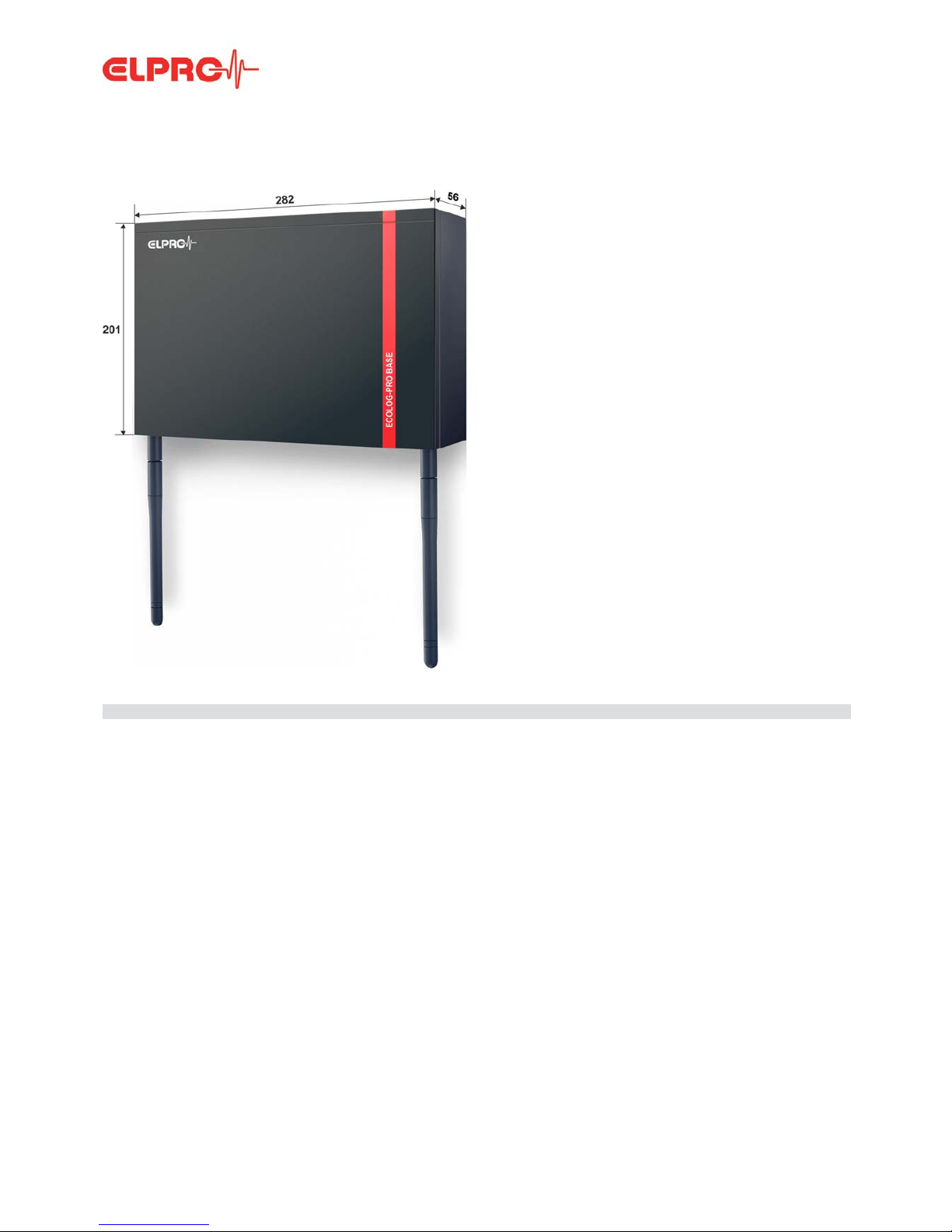
1 ECOLOG-PRO Base
Description
The ECOLOG-PRO Base is a simple, autonomous
central monitoring unit for the network-capable
ECOLOG-PRO and ECOLOG-NET data loggers. It is the
kernel of the Plug&Play solution for the networked
monitoring of rooms and equipment. All the required software is pre-installed on the PC designed for maximum
reliability. It provides extensive compatibility with proven
ECOLOG-NET data loggers and ECOLOG-PRO
modules.
This manual is a quick and simple reference guide to
initial startup of up the ECOLOG-PRO Base. However, it
contains no basic principles on setting up or operating a
network.
ECOLOG-PRO Base, 801417
Application:
Maximum number of measuring
data points
50 measuring data
points
Memory capacity 18 months, older data is automatically deleted month by month by the system.
Data security - Internal non-volatile memory
- External USB drive, drive letter G
Data logger compatibility ECOLOG-NET, ECOLOG-PRO
Internal clock - Drift ± 11 minutes / year
- Backup battery
Antennas The device may only be operated with the supplied antennas.
IMPORTANT: Do not use an extension cable between the ECOLOG-PRO Base
and the antenna connections.
WLAN 2.4 GHz and 5 GHz, WPA2 or no encryption

Document: EP6002Eb
ECOLOG-PRO BASE
5 - EN
Power supply External power supply unit
Follow the safety and application instructions for the power supply unit. Only
operate the device using the supplied power supply unit. Use of an incorrect
power supply unit may cause damage to the device. Always replace defective
or damaged power supply units.
UPS batteries Material safety data sheets in compliance with EEC Directive 93/112/EC and
shipment recommendations are available from ELPRO. Do not subject batteries
to mechanical stress or damage them. Leaking battery fluid is highly corrosive
and may generate severe heat or may cause a fire if it comes in contact with
moisture.
Environmental conditions Application: 0°C to 40°C
Temperatures above 100°C may damage the battery.
Application: 10% RH to 95% RH, non-condensing
Protection class: IP20, ingress of water / humidity may cause damage to
the device.
IR radiation (heat) and superheated steam may damage the surface
coating of the casing.
No guarantee can be given if functions exceed the specified threshold
range.
MAKE SURE THE ECOLOG-PRO BASE IS AT ROOM TEMPERATURE BEFORE INITIAL STARTUP.
Casing To clean the modules, use a slightly moist cloth. Never use thinner,
gasoline, alcohol, or any other cleaning agents since they may damage
the casing.
Installed applications elproMONITOR
Configuring and monitoring data loggers.
SM3031Db
elproUSER
elproMONITOR user management.
SU6031D
elproEVENT
Audit trail which complies with the cGxP Environment requirements of
elproMONITOR.
SV6031D
ECOLOG-PRO Base Maintenance
Software for initial startup, setting, and maintenance of the
ECOLOG-PRO Base
3 ECOLOG-PRO Base Maintenance
elproMONITOR-WebAccess
Service on the server for creating text files that are required for the web
application elproLOG MONITOR-WebAccess. This optional web application must be installed on a separate web server.
Document: EP6002Eb
INITIAL STARTUP
6 - EN
2 Initial Startup
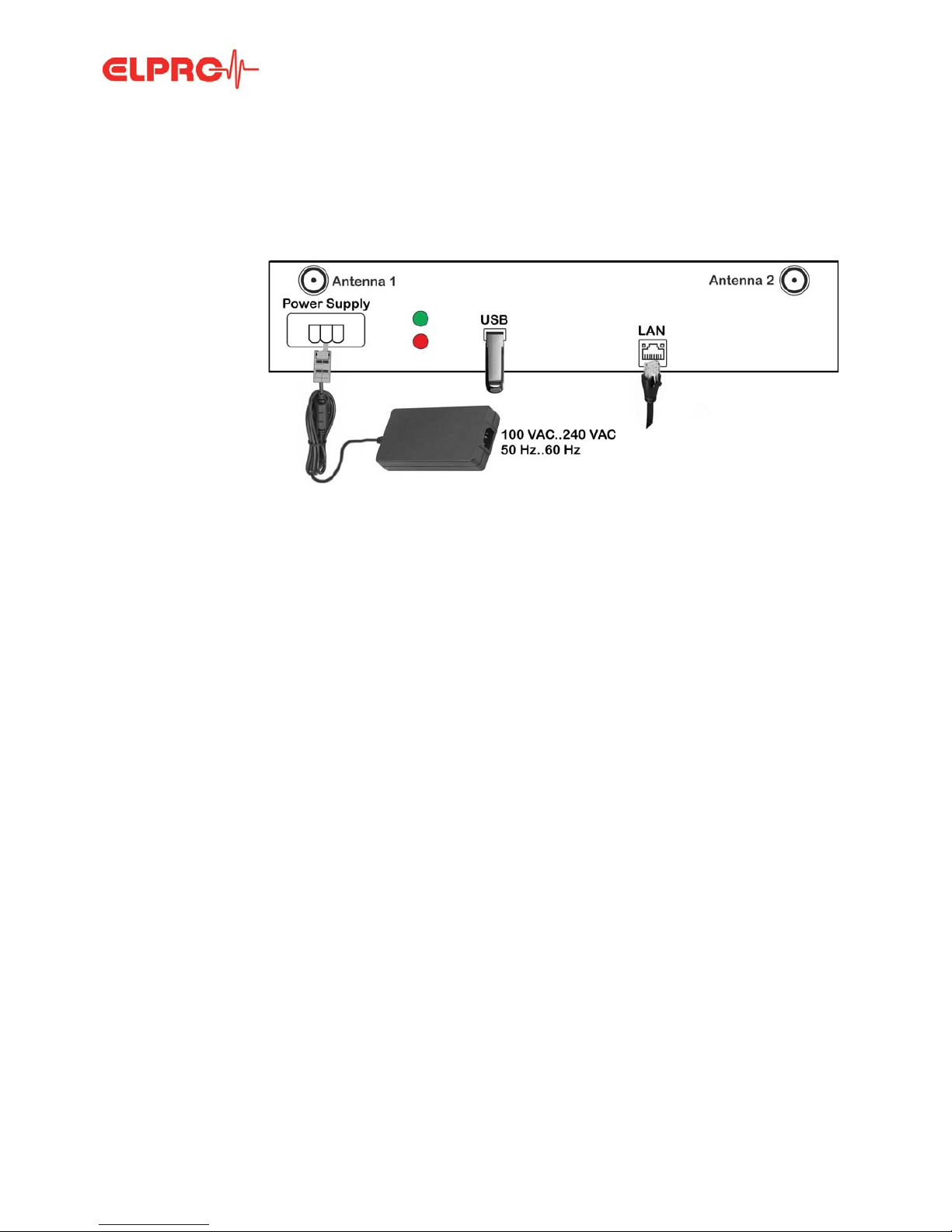
2.1 ECOLOG-PRO Base
Casing underside, position of sockets, indicators, and antennas
Connections Depending on the operating mode, the ECOLOG-PRO Base is connected only to the power
supply unit or additionally to a network cable.
Optionally, an external data memory drive can be connected to the USB port provided (USB
3.0). This connection is also used for configuration, updates, and service work by ELPRO.
Note on initial startup The sections: 2.1 ECOLOG-PRO Base to 2.3 WLAN Connection are also described in the
document: EP6401A which is supplied along with the ECOLOG-PRO Base.
LEDs and connections Confirmation tone sequence
LED, green Power on Start 1 long acoustic signal
LED, red Hard disk active Success 2 short acoustic signals
Power supply Socket for external power supply
unit
Error 2 long acoustic signals
Antenna 1, 2 WLAN antenna connection
USB USB port for data exchange
and initialization.
Drive letter G
LAN Gigabit Ethernet LAN port
Document: EP6002Eb
INITIAL STARTUP
7 - EN
2.2 LAN Connection
Step 1
Step 2
Step 3
Step 4
Step 5
Step 6
2.3 WLAN Connection
Step 1
Step 2
Step 3
The PC used for configuration must be in the same network as the ECOLOG-PRO
Base.
Connect the cable and power supply
unit.
ECOLOG-PRO Base starts.
Start process. Wait for the confirmation tone indicating ready
(operating system started).
Plug in the USB stick. Wait for the confirmation tone (Success, Error).
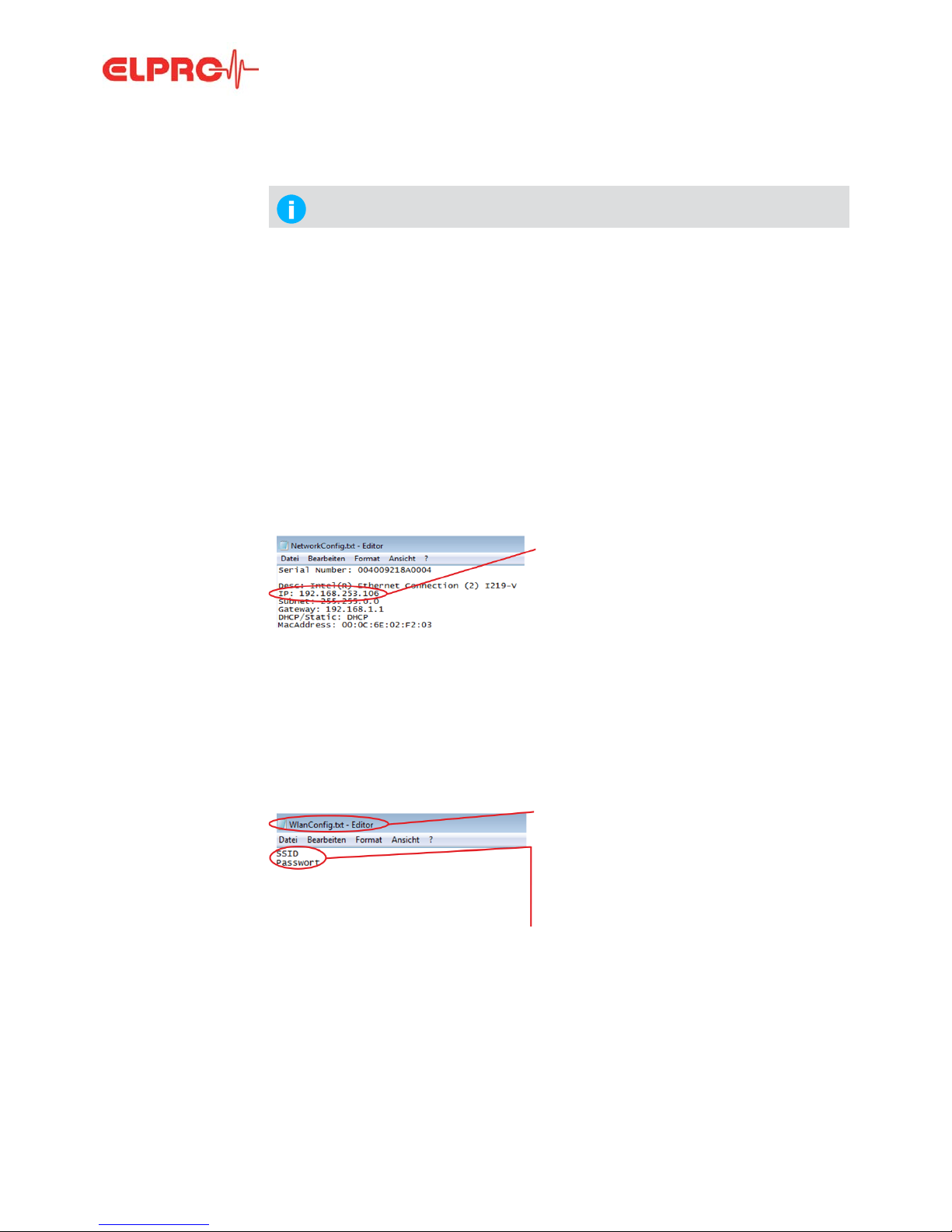
Remove the USB stick.
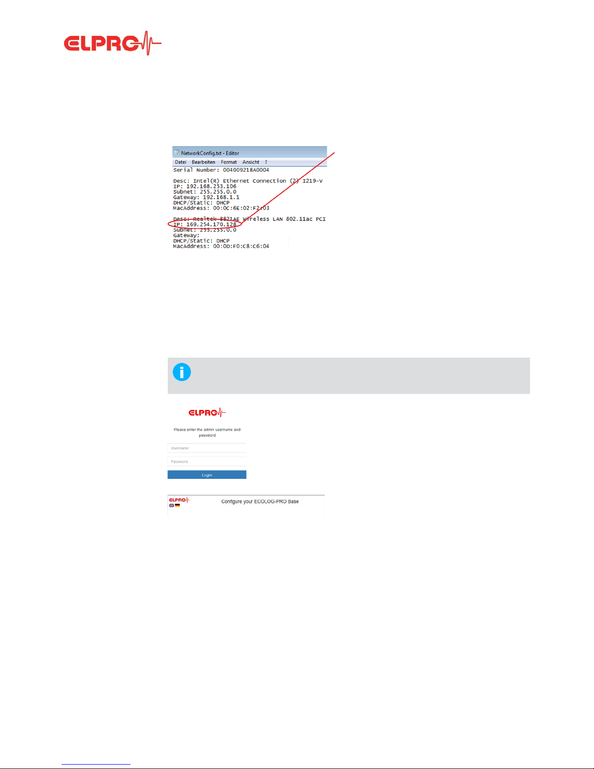
Plug the USB stick in the PC. File: Open the file NetworkConfig.txt.
Use the IP address below the line “Desc: Intel(R)
Ethernet Connection (2) I219-V" to log in to the
ECOLOG-PRO Base.
Open your web browser and run
initialization.
2.4 Initialization
Path: http://192.168.253.106/Maintenance
Create the file WlanConfig.txt on a USB stick.
Enter the SSID name in the first line and the
WLAN password in the second line.
If a password is not required for the WLAN, leave
this line blank.
Encryption is set to WPA2.
Connect the power supply unit.
ECOLOG-PRO Base starts.
Plug in the USB stick. Wait for the confirmation tone (Success, Error).
Document: EP6002Eb
INITIAL STARTUP
8 - EN
Step 4
Step 5
Step 6
2.4 Initialization
Login
Language
Remove the USB stick.
Plug the USB stick in the PC. File: Open the file NetworkConfig.txt.
Use the IP address below the line “Desc: Realtek
8821AE Wireless LAN 802.11ac PCI-E NIC" to
log in to the ECOLOG-PRO Base.
Open the web browser and run
initialization.
2.4 Initialization
Path: http://192.168.253.106/Maintenance
At initial startup, the ECOLOG-PRO Base is initialized by the configuration wizard
on the ECOLOG-PRO Base. To carry out this configuration, make sure the LAN
or WLAN is connected to the ECOLOG-PRO Base.
Log in to the ECOLOG-PRO Base using the
username and password set on delivery.
- Username: admin
- Password: elpro
Select the initialization language by left-clicking
the country flag of your choice.
 Loading...