

Page 1
Ethernet module LAN / WLAN
Digi Device Connect ME / Wi-ME
Operation Manual
ab Firmware:
- LAN >=F3/E
- WLAN >=G/F
Page 2

Contents
1. General Informations..........................................................................4
1.1 IP Addressing ....................................................................................4
1.2 PoE- Power over Ethernet..................................................................4
1.3 WLAN - Wireless LAN........................................................................4
2. Status of Datalogger...........................................................................7
2.1 ECOLOG-NET Default Configuration at Delivery.................................7
2.2 Details on WLAN Datalogger..............................................................7
3. Digi Device Discovery Tool ...............................................................8
3.1 Overview ...........................................................................................8
DE
3.2 Digi Device Discovery Start Screen ....................................................9
3.3 Web Interface Overview...................................................................10
3.4 Menu Configuration..........................................................................11
3.5 Menu Administration ........................................................................14
4. Reset to Status at Delivery- Hardware Reset...............................16
4.1 HOTBOX-PRO Version Information..................................................16
4.2 ECOLOG-NET LP4,WP4 Version Information...................................16
4.3 ECOLOG-NET LH2, WH2 ................................................................16
4.4 ECOLOG-NET LA8, WA8.................................................................16
4.5 Reset module ECOLOG-NET...........................................................17
5. How to Configure?............................................................................18
5.1 Configure a LAN Datalogger.............................................................18
5.2 Example: Different Digi Device Discovery Views ..............................20
5.3 Example: Configure Network Settings Ad hok (LAN) .........................21
5.4 Example: Overview WPA-PSK Settings with AES .............................22
5.5 Example: ELPRO Internal Testing Environment ................................23
IT
ES
EN
FR
IT
ES
6. Module Specifications......................................................................24
6.1 LAN devices ...................................................................................24
6.2 Wireless LAN devices ......................................................................24
6.3 LED Status Overview.......................................................................25
7. Glossary..............................................................................................26
8. ELPRO Customer Service Information..........................................30
9. Revision History................................................................................31
Operation manual LAN / WLAN ethernet module
IT6001Ed
EN - 2
Page 3
In the interest of our customers we reserve the right to
make any changes resulting from technical advances.
Therefore, schemes, descriptions and extent of delivery are subject to change without notice!
Used symbols
Reference
IMPORTANT INFORMATION OR WARNING
DE
EN
FR
Reference to resuming chapter or document
Introduction
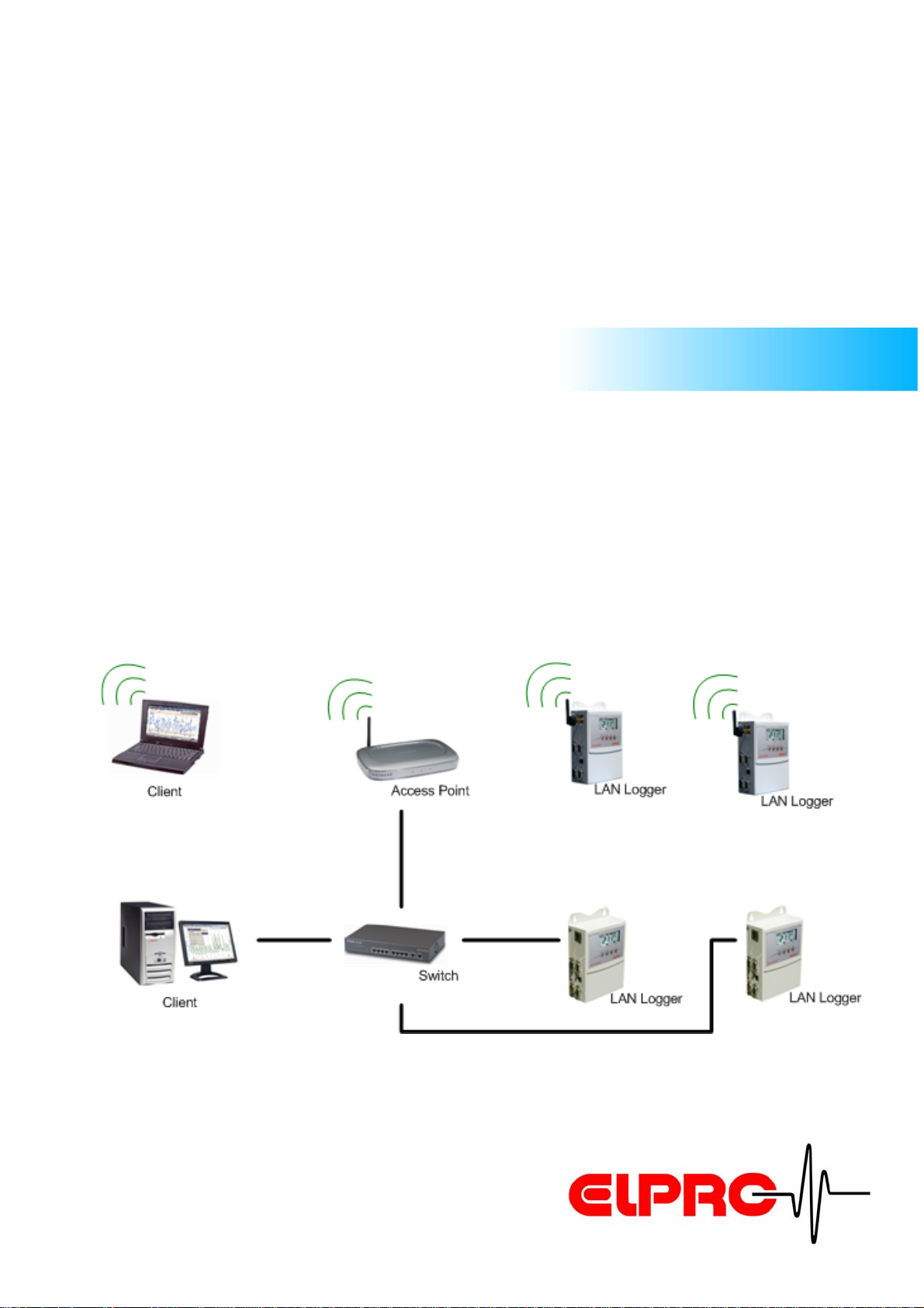
ELPRO network datalogger series are designed for recording various physical signals like temperature and relative
humidity via a network.
The data is stored in the internal memory and can be loaded
to the PC via the LAN network. The system offers the very
highest of data safety as the datalogger continues logging
for months even in the event of a power failure running from
its own internal lithium battery (Except LA8 and WA8). Multiple level alarm features are built in for local or network alarming in for any user set out of range conditions.
IT
ES
IT
ES
Operation manual LAN / WLAN ethernet module
IT6001Ed
EN - 3
Page 4
1. General Informations
1.1 IP Addressing
General Informations
The IP addressing determines the bases of the connection
of a client on the datalogger. For constant access we recommend static IP. In elproLOG CONFIG the datalogger with the
respective IP address is stored. If this is not fixed, the monitoring function of the elproLOG MONITOR cannot be ensured.
ATTENTION
For safety reason we recommend to use static IP
adresses.
1.1.1 DHCP
If you want to use DHCP, configure the DHCP service in
such a way that the assigned IP address of the dataloggers
do not change.
For more details about the DHCP service ask your IT
personel.
Static IP
Dynamic IP
IT
DE
EN
FR
IT
1.2 PoE- Power over Ethernet
D Voltage supply over ethernet
D Special switch or Hub with support of PoE
D Use of the two unused pairs of wires.
ATTENTION
We recommend power transmission over the two unused pairs (spare-wire).
1.3 WLAN - Wireless LAN
The Wireless LAN dataloggers are a common wireless client
devices and support different standards such as
IEEE802.11b and EEE802.11i.
Characteristics PoED No power sockets next to the datalogger
Spare-wire
Check environment with
your IT personel.
ES
ES
Operation manual LAN / WLAN ethernet module
IT6001Ed
EN - 4
Page 5
We recommend to use a standard (open shared)
Access Point to connect to the datalogger(s) and to
configure the settings for the internal wireless environment.
General Informations
For more details see chapter 5.
How to Configure?
.
1.3.1 General Guidelines
We recommend to specified the following items before install
a wireless environment:
• Signal strenght, channel, etc.
• Place and location of the devices
• Client with elproLOG MONITOR should be connected
over ethernet LAN.
• Standard Settings (Open shared)
- NO security settings
- DHCP (For first configuration possibilities)
• Compatible with 802.11b adapters
• WPA/WPA2/ (Wireless Protected Access)
•MAC Filter
1.3.2 Use Existing Wireless Environment
Environment• National Restrictions
Access Point
initial operation
Operation generally• Wireless Security such as:
IT
DE
EN
FR
IT
Previous, check the following points with your IT personel:
D Is it possible to insert new devices?
D Existing safety guidelines can be configured on the
datalogger?
Each additional node of a wireless network affects
the entire Wireless environment.
D Is it possible to operate parallel with further wireless
network?
D Other WLAN restrictions (channel,...)
Operation manual LAN / WLAN ethernet module
IT6001Ed
Insert datalogger in an
existing enviroment
to connect in parallel
EN - 5
ES
ES
Page 6

1.3.3 Configure a new environment
Placement
General Informations
We recommend to measure the environment previous, in
order to be able to determine locations of the datalogger and
access points. Wireless connection will be stronger the closer the devices are to the Access Point.
Nuisance
Objects that can inhibit wireless communication include:
• Other wireless environments
•Microwave
• Refrigerators
• Metal cabinets
• Large aquariums
• Metallic-based UV tinted windows
Measurment
Nuisance
DE
EN
FR
IT
ES
IT
ES
Operation manual LAN / WLAN ethernet module
IT6001Ed
EN - 6
Page 7
2. Status of Datalogger
Unless otherwise specified, dataloggers are delivered with
the following standard values.
Status of Datalogger
Pre-configuration
If desired, ELPRO-BUCHS AG or your responsible
distributor configure the required parameter for all
ethernet dataloggers.
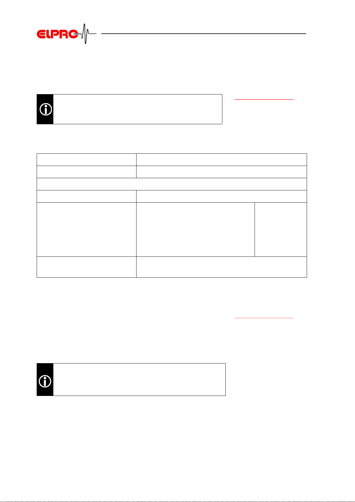
2.1 ECOLOG-NET Default Configuration at Delivery
Login elpro
Network Configuration automatic configuration (DHCP)
Serial Port Settings
• TCP Server Settings TCP Port 2101
• Basic Serial Settings - Baud Rate
- Data Bits
-Parity
- Stop Bits
- Flow Control
• Advanced Serial
Settings
Send after 5ms and 300 bytes
57600
8
None
1
None
IT
DE
EN
FR
IT
2.2 Details on WLAN Datalogger
WH2, WP4 and WA8 have additional wireless settings as follows:
• Connect to any available wireless network (no SSID)
• Channel: auto-scan
We recommend to save the configured status. For
more Information see chapter 3.5.1
Operation manual LAN / WLAN ethernet module
IT6001Ed
Backup / Restore
Wireless special
.
EN - 7
ES
ES
Page 8

Digi Device Discovery Tool
3. Digi Device Discovery Tool
3.1 Overview
The main challenge is getting the Digi Module to associate
with the network. Once this is accomplished the digi can be
further configured by using the Digi Device Discovery web
interface.
3.1.1 Status at Delivery
At delivery the datalogger is ready for use. Only the respective IP address or special wireless settings have to be configured.
3.1.2 Digi Device Discovery
Here, the most important features can be configured, i.e. you
can make TCP/IP settings, restart the module and open the
web interface.
3.1.3 Web Interface
The web interface is needed for configuring the network
parameters of the datalogger. (e.g. wireless specification)
Chapter 3.2 Digi Device
Discovery Start Screen
Chapter 3.3 Web Interface Overview
IT
ES
DE
EN
FR
IT
ES
Operation manual LAN / WLAN ethernet module
IT6001Ed
EN - 8
Page 9

Digi Device Discovery Tool
3.2 Digi Device Discovery Start Screen
Run Digi Device Discovery software by click on Start - Program - Elpro - Elpro Device Discovery.
DE
EN
1 Device Task • Open web interface
• Configure network settings
• Restart device
2 Other Task • Refresh view
• Help and Support
3 Details • Shows the most important characteristics of the marked
datalogger
4 Main view • Shows all found devices in the same network.
IT
ES
FR
IT
ES
Operation manual LAN / WLAN ethernet module
IT6001Ed
EN - 9
Page 10
Digi Device Discovery Tool
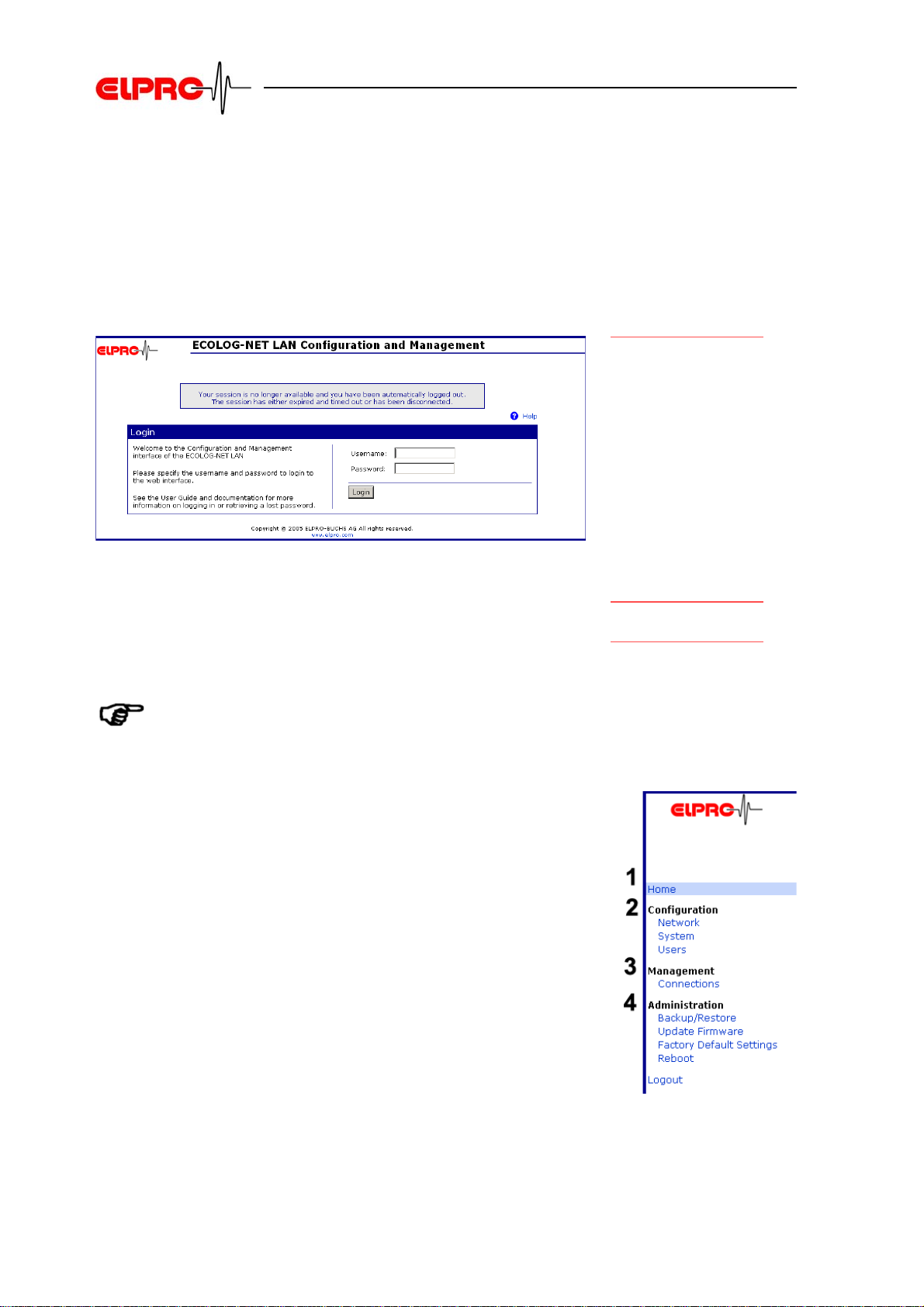
3.3 Web Interface Overview
Start the "Web Interface" by double-clicking the relevant
datalogger in the Digi Device Discovery or via the "Open web
interface" link.
3.3.1 Start screen
For more information about the menus.
Username: elpro
Passwort: elpro
See chapter 3.4.3
Users
User mask login
Help
Login
IT
DE
EN
FR
IT
1 Home
"Home" shows the General LAN and WLAN network configurations.
2 Configuration
Necessary values for the network and user parameters.
3 Management
Overview of current settings and connecting conditions.
4 Administration
General administration possibilities of the Digi Device Diysovery are available.
Operation manual LAN / WLAN ethernet module
IT6001Ed
EN - 10
ES
ES
Page 11

Digi Device Discovery Tool
3.4 Menu Configuration
3.4.1 Network - LAN module
IP Settings
In order to integrate the datalogger in an
existing network, an IP number must be
assigned. It must be in the same range as
the client's IP number.
Network Service Settings Advanced Network Settings
DE
Network Service Settings and Advanced Network Settings are not changed.
3.4.2 Network - WLAN module
This wireless network interface can be used to communicate to wireless networks
using 802.11b technology. Contact your administrator or consult your wireless access
point documentation for the settings required to setup the wireless network configuration.
IT
ES
EN
FR
IT
ES
IP Settings
In order to integrate the datalogger in an
existing network, an IP number must be
assigned. It must be in the same range as
the client's IP number.
Operation manual LAN / WLAN ethernet module
IT6001Ed
EN - 11
Page 12

Wireless LAN Settings
Wireless Security Settings
Digi Device Discovery Tool
Different connection settings can be
stored. Please consider the respective delimitation data of the used access points.
• SSID (Network name)
• Country
• Channel
• Transmit power
DE
Wireless Security Settings are used to
make specific settings for WEP or WPA.
• authentication method
• Encryption method
• WEP Keys
• WPA PSK
• Username/password
Security key
Different key combinations and
lengthen can be stored. Please
consider the respective delimitation
data of the used access points.
CCMP uses the Advanced Encryption
Standard (AES) algorithm.
IT
ES
EN
FR
IT
ES
Operation manual LAN / WLAN ethernet module
IT6001Ed
EN - 12
Page 13

Wireless 802.1xAuthentication Settings
Digi Device Discovery Tool
These options are only configurable when
"WEP with 802.1x authentication" or "WPA
with 802.1x authentication" are enabled on
the "Wireless Security Settings" tab.
DE
EN
Network Service Settings Advanced Network Settings
Network Service Settings and Advanced Network Settings are not changed.
IT
ES
FR
IT
ES
Operation manual LAN / WLAN ethernet module
IT6001Ed
EN - 13
Page 14

Digi Device Discovery Tool
3.4.3 Users
All necessary standard settings for an usual environment where given by the user
elpro. For special settings like "Serial Port" changes contact ELPRO-BUCHS AG.
3.5 Menu Administration
DE
3.5.1 Backup / Restore
Backup
Press on "Backup " to save a *.cfg file to
your workspace.
3.5.2 Update Firmware
The configuration of this digi device can be
saved to a file. This configuration file can
be used to configure this or any other digi
device module.
ATTENTION
IP address is stored as well!
Restor
With click on "Restore" you request to load
the *.cfg configuration file from your
workspace.
New firmware updates can be made.
IT
ES
EN
FR
IT
ES
Contact ELPRO-BUCHS AG to check the possible
Firmware Version for your devices.
Operation manual LAN / WLAN ethernet module
IT6001Ed
EN - 14
Page 15

3.5.3 Factory Default Settings- Software Reset
Restoring the factory default settings will
clear all current settings and set the module
back to the default configuration.
Digi Device Discovery Tool
Kapitel 2.1
Configuration at Delivery
Choosing this option will restore the settings your Digi device server originally shipped
with. Check Keep network settings to keep the current network settings such as the IP
address.
Reboot
After the reset, a reboot has to be made with the Digi Device Discovery tool.
D Run "Digi Device Discovery"
D Mark device
D Run "Restart Device
ECOLOG-NET Default
3.5.4 Reboot
We recommend to restart the module after
each change.
IT
DE
EN
FR
IT
Different possibilities for reboot or restart the device:
-by Power OFF / ON
- by start the Digi Device Discovery Tool -> choos Reboot
- or by using the Web Interface -> Reboot
ES
ES
Operation manual LAN / WLAN ethernet module
IT6001Ed
EN - 15
Page 16

Reset to Status at Delivery- Hardware Reset
4. Reset to Status at Delivery- Hardware Reset
4.1 HOTBOX-PRO Version Information
The HOTBOX-PRO devices have to be sent back to
ELPRO-BUCHS AG.
4.2 ECOLOG-NET LP4,WP4 Version Information
4.2.1 PCB no. 2003xxxx
Devices until PCB number [2003xxxx] have to be sent back
to ELPRO-BUCHS AG.
The PCB number is shown in the status of the datalogger.
4.2.2 PCB no.2004xxxx
For reset the devices with PCB number [2004xxxx] see
chapter 4.5
Reset module ECOLOG-NET
.
Status view
Reset LP4 / WP4
IT
ES
DE
EN
FR
IT
ES
4.3 ECOLOG-NET LH2, WH2
For reset the ECOLOG-NET LH2 and WH2 devices, see
chapter 4.5
Reset module ECOLOG-NET
.
4.4 ECOLOG-NET LA8, WA8
For reset the ECOLOG-NET LA8 and WA8 devices, see
chapter 4.5
Operation manual LAN / WLAN ethernet module
IT6001Ed
Reset module ECOLOG-NET
.
Reset LH2 / WH2
Reset LA8 / WA8
EN - 16
Page 17

Reset to Status at Delivery- Hardware Reset
4.5 Reset module ECOLOG-NET
In order to set the equipment on the delivery status back, the
device floor must be removed. The reset possibility is next to
the ethernet module.
Afterwards following the next steps:
1. Place jumper in position A.
2. Connect the power supply with the device.
3. Wait, until the orange/green LED of the Digi module
flash in a code of 1-1-5.
4. ATTENTION: Do not remove power supply!
5. Wait for less than 1 minute.
6. If the orange or green LED is flashing, the device is in
configuration at delivery status.
LH2, WH2, LP4, WP4,
LA8, WA8
1. Place Jumper
2. Power on
4. Remove Jumper
6. Conclusion
DE
EN
FR
7. Close the device by place the device floor.
8. Configure IP Adresse and network settings if needed.
LH2 / WH2 LP4 / WP4 LA8 / WA8
7. Close the device
8. Network settings
IT
ES
IT
ES
Operation manual LAN / WLAN ethernet module
IT6001Ed
EN - 17
Page 18

5. How to Configure?
5.1 Configure a LAN Datalogger
How to Configure?
To identify a datalogger in a LAN / WLAN environment, each
datalogger gets a unique address. This address is made of
3 different parts, these parts are called: IP Address &
Subnet Mask & Default Gateway.
To avoid communication problems, the system administrator
should release the network addresses prior installation!
Consequently, the address information must be entered
manually into each datalogger.
5.1.1 Pre-configuration for LAN Installation
1. Power-up the datalogger
2. Connect the ECOLOG-NET L... datalogger to your pc
by using a crossover LAN cable.
3. Watch the status LEDs located on the LAN module:
- As soon as a stable link between the datalogger and
the pc has been established, the orange LED is
alight permanently
- Blinking of the green LED indicates data traffic.
- Other status see chapter 6.3
Overview
.
LED Status
ECOLOG-NET - this is
the ELPRO datalogger
family with LAN or
WLAN communication
capabilities.
Power ON
LED status
(until 1min. delay)
IT
DE
EN
FR
IT
4. Configer IP address
5.1.2 Configuration for WLAN Installation
need a running Access Point with dhcp Client and a pc/laptop connected to it. This Access Point has to propagate its
SSID and the following security settings have to be switched
off: WEP, WPA and MAC filtering. (Open shared)
For more details about these settings talk to your IT department or refer to the
documentation of the used access-point.
If you face problems by switching off all security settings on the access-point
in use, we recommend using temporarily a second access-point just for the
set-up of the dataloggers.
ES
ES
RequirementsTo set-up an ECOLOG-NET W... logger you are going to
Operation manual LAN / WLAN ethernet module
IT6001Ed
EN - 18
Page 19

Follow the next steps to etablish a connection:
How to Configure?
1. Specify the required devices and placement
2. Specify the required IP addresses and network security
settings:.
- IP range, SSID, Channel, Security
3. Start Access Point and Laptop in default configuration.
(Open shared)
4. Power-up the datalogger and watch the status LEDs
located on the WLAN module:
- As soon as a stable link between the datalogger and
the access-point has been established, the orange
LED is alight permanently.
- Blinking of the green LED indicates data traffic.
- Other status see chapter 6.3
LED Status
Overview
5. Configure "Network Settings" via Web interface
- Menu Configuration -> Network -> IP Settings
- After "Apply" start reboot procedure.
6. Configure Access Point to required IP settings:
- Set IP address of the Access Point.
7. Configure required "Wireless LAN Settings" on the
datalogger (SSID, Channel,...):
- After click on "Apply" change to "Wireless Security
Settings".
Specification
Power ON
Check LED status
(delay up to 1 min.)
IP settings
WLAN Settings
datalogger
IT
DE
EN
FR
IT
8. Configure "Wireless Security Settings" on the datalogger (WEP, WPA,...):
- After click on "Apply" reboot the datalogger.
9. Configure Access Point and Laptop to required Wireless Network Settings (SSID, Security,...)
10. Check if datalogger has connected to existing environment.
-via ping
-via Digi Device Discovery Tool
- via logfile of the Access Point
All devices on your network must use the same security mode in order to communicate.
WLAN Settings
Access Point, Client
ES
ES
Operation manual LAN / WLAN ethernet module
IT6001Ed
EN - 19
Page 20

How to Configure?
5.2 Example: Different Digi Device Discovery Views
DE
EN
Wrong IIP adress range
IP address or subnet mask of the datalogger are in a different address range then the required computer or laptop.
Firmware < F3
ECOLOG-NET L... datalogger delivered before 12/2005 use
Firmware < F3. Possible other Digi devices are shown in the
same way.
Firmware >=F3
From firmware version F3 or higher includes user configuration and further WLAN configuration possibilities. See
Details for your firmware version.
see chapter 3.5.2
Update Firmware
Exclamation mark
Firmware < F3
other Digi Device
Firmware >=F3
IT
ES
FR
IT
ES
Operation manual LAN / WLAN ethernet module
IT6001Ed
EN - 20
Page 21

How to Configure?
5.3 Example: Configure Network Settings Ad hok (LAN)
RequirementsIn this example following settings for datalogger are requi-
red:
• IP: 192.168.112.201
• SN: 255.255.254.0
Procedure1. Note your configuration on your laptop. (Printscreen)
DE
EN
2. Change the IP adress and subnet mask of your laptop
to:
• IP: 192.168.112.10
• SN: 255.255.254.0
3. Connect the dataloggers via red crossover cable
directly to your laptop and power on.
4. Now change the dataloggers IP and subnet to the
required settings.
5. Connect the dataloggers to the customer LAN.
6. Check Configuration via the customers pc with Digi
Device Discovery tool.
7. If no red exclamation mark -> the dataloggers are configured in the correct way, and elproLOG and Monitor
should run.
8. If exclamation mark -> check the IP adress and subnet
mask of the required customer pc/laptop with the
network administrator.
9. Change settings back on your laptop.
IT
ES
FR
IT
ES
The subnet mask should be 255.255.254.0 or similar but not 255.255.255.0 in
this example.A computer subnet mask with 255.255.255.0 could not connect
properly to the datalogger.
Operation manual LAN / WLAN ethernet module
IT6001Ed
EN - 21
Page 22

How to Configure?
5.4 Example: Overview WPA-PSK Settings with AES
IP Settings Wireless LAN Settings
Wireless LAN Settings
DE
EN
IT
ES
FR
IT
ES
Operation manual LAN / WLAN ethernet module
IT6001Ed
EN - 22
Page 23

How to Configure?
5.5 Example: ELPRO Internal Testing Environment
DE
EN
In our internal testing environment we are using following
Conditions:
• Communication ranges below 10m
• No solid obstacles in between
• Different Access Points like:
• Belkin Pre-N Router
• Linksys WRT54G
• Dlink DWL2000AP+
This are symple Access Points for small testing environment. To find out a suitable Access Point area, restrictions and dimension have to be checked.
IT
ES
FR
IT
ES
Operation manual LAN / WLAN ethernet module
IT6001Ed
EN - 23
Page 24

6. Module Specifications
6.1 LAN devices
6.1.1 Environmental
Operating temperature: -40ºC to +85ºC (-40ºF to +185ºF)
Relative humidity: 5% to 90% (non-condensing)
Module Specifications
Altitude: 12,000 ft (3657.6 m)
6.1.2 Network Interface
• Standard: IEEE 802.3
• Physical Layer: 10/100Base-T
• Data rate: 10/100 Mbps
• Mode: half-duplex or ful-duplex
• Connector: RJ-45
6.2 Wireless LAN devices
6.2.1 Environmental
Operating temperature: -20ºC to +75ºC (-4ºF to +176ºF)
Relative humidity: 5% to 90% (non-condensing)
Altitude: 12,000 ft (3657.6 m)
6.2.2 Network Interface
Standard: IEEE 802.11b
IT
ES
DE
EN
FR
IT
ES
Frequency: 2.4 GHz
Data rate up to 11 Mbps with automatic fallback
Modulation:
• CCK (11/5 Mbps), DQPSK (2 Mbps), DBPSK (1 Mbps)
Transmit power: 16 dBm typical
6.2.3 Sensitivity
1Mbps: -92 dBm
2 Mbps: -89dBm
Antenna connector: 1 x RP-SMA
Operation manual LAN / WLAN ethernet module
IT6001Ed
5.5Mbps: -87 dBm
11Mbps: -82 dBm
Receive Sensitivity
EN - 24
Page 25

6.2.4 Wreless Security
WEP (Wired Equivalent Privacy)
• 64/128-bit encryption (RC4)
WPA2/802.11i
• 128-bit TKIP/AES encryption
• 802.1x EAP authentication
• LEAP (WEP only), PEAP, TTLS, TLS
•GTC, MD5, OTP, PAP, CHAP, MSCHAP,
MSCHAPv2, TTLS-MSCHAPv2
•GTC, MD5, OTP, PAP, CHAP, MSCHAP,
MSCHAPv2, TTLS-MSCHAPv2
• Enterprise and Pre-Shared Key (PSK) mode
Module Specifications
DE
CCMP basiert auf dem Advanced Encryption Standard (AES).
6.3 LED Status Overview
When a problem is encountered on a digi module, the network activity LED will flash with a 3 digit code. Here is a
listing of the most common codes encountered.
Code Meaning Resolution
1-1-1
1-1-5
2-2-5
Initialisation
• All test passed
• starting EOS
The device is being reset to factory defaults.
The application image is corrupted.
Modul started correct
No action required
Jumper is set.
Execute reset as per description.
No action required
Device has to be send back to
ELPRO Buchs AG.
IT
ES
EN
FR
IT
ES
Operation manual LAN / WLAN ethernet module
IT6001Ed
EN - 25
Page 26

Glossary
7. Glossary
Access Point Base station or central node device that provides the client
with wireless network connection within a certain range.
Ad hoc Supports direct peer-to-peer communication, i.e. direct net-
work card to network card connection.
Broadband Broadband describes the range of frequency of a carrier
medium (cable, wireless channel). The wider the band of frequencies, the more information can be transmitted in a given
amount of time.
Broadcast A broadcast in a computer network environment sends data
packets from one destination simultaneously to all the participating devices on the network . A broadcast is mainly used
when the address of the recipient is unknown. Similarly, a
broadcast sends the same message to multiple recipients at
the same time. Every broadcast recipient must automatically
accept the delivered message and decide whether the message must be processed. The recipient can judge the relevance of the message and discard any message deemed
inappropriate.
DE
EN
FR
Client Whether in a network or standalone workstation, a client is
the required workstation or laptop. The elproLOG software
(Version 3.30.x upwards) is installed on the client to enable
readout at the network-integrated Ecolog-Net dataloggers.
DHCP The DHCP (Dynamic Host Configuration Protocol), backed
by an appropriate server, enables dynamic allocation of an
IP address and other configuration parameters to computers
on a network (e.g. internet or LAN). DHCP allows a new
computer to be added to an existing network without further
configuration steps. Without DHCP, a relatively complicated
Setup is required; the IP address and other required parameters such as netmask, gateway, DNS server, WINS server, etc. must be entered manually. DHCP can automate the
assignment of these parameters when starting a new computer to a network.
Ethernet A collective term for a series of baseband networks with dif-
ferent topologies which all use the CSMA/CD access
method. It has become the most widespread LAN technology in use.
Ethernet Connection Networking cables connect the PCs on a network to the cen-
tral network hub or switch. Most Ethernet networks use a
type of cable known as Twisted Pair Cable (also known as
Category 5 cable) .A RJ45 network connector is used.
IT
ES
IT
ES
Operation manual LAN / WLAN ethernet module
IT6001Ed
EN - 26
Page 27

Glossary
Firewall A security application which protects a server, a subnet or all
end user resources from unauthorized access or outside
attacks. The firewall can perform these functions for a single
standalone computer, it can be integrated in routers or switches and it can be integrated as a software program in the
operating system.
Flow Control Function on the network layer of the OSI model (Layer 3)
which manages the rate of data flow so that the data can be
handled at an efficient pace; i.e. it prevents a fast sender
overflowing the receive buffer of a slower recipient by allowing the sender to send only as much data as the recipient
can cope with.
Gateway A gateway operates at the highest level (Layer 7) of the OSI
model and enables communication between computers that
are integrated in otherwise incompatible networks. A gateway essentially works like a router but, in addition, acts at
higher levels performing code and protocol conversion (character sets).
DE
EN
Hub An active (cf. switch) or passive junction device that con-
nects multiple network lines from various workstations on
one single line.
IEEE Institute of Electrical and Electronic Engineers - a technical
committee with more than 350,000 members in more than
150 countries. The IEEE publishes technical literature to
inform the membership of new and further developments,
initiates conferences and is responsible for creating, enforcing and promoting industrial standards.
IEEE 802 The IEEE 802 is an individual working group responsible for
developing standards for the two lower layers in the ISO/OSI
reference module for local networks.
IEEE 802.11 The IEEE 802.11 is an individual working group responsible
developing standards for wireless local area network technology. These wireless local area networks are often called
Wireless LAN, WLAN or WiFi.
Intranet A private network based on internet technology which imple-
ments IP as network protocol and uses web-based applications.
IT
ES
FR
IT
ES
IP Internet Protocol; the main function of IP is to find the ideal
path for transmission of data packets from the sender via
several networks to the recipient (routing). IP operates at the
network layer of the OSI model (Layer 3). Delivery is packetoriented and connectionless.
Operation manual LAN / WLAN ethernet module
IT6001Ed
EN - 27
Page 28

Glossary
LAN Local Area Network; a computer network that spans a rela-
tively small area. Most LANs are confined to a single building
or part of one building (one level) and are controlled by one
administrative authority. Usually LANs also use a file server
concept for data, disk and periphery management which
allows all network users shared access to the information.
MAC Address Media Access Control; a unique hardware address that iden-
tifies network components. The MAC address is usually on
the back side of the device. The MAC address is 48 bits long
and MAC addressing operates at the data link layer (Layer
2) of the OSI model.
Peer to Peer A type of network in which each workstation has equivalent
capabilities and responsibilities. This differs from client/server architectures, in which some computers are dedicated to
serving the others. The advantage of peer-to-peer systems
is the simplicity; it requires no special knowledge of network
programming. The primary disadvantage of peer-to-peer
systems is the security vulnerability which can result in
unauthorized data access.
Router Network components which operate at the network layer of
the OSI model (Layer 3). As opposed to hubs and switches,
routers are always protocol-dependent (e.g. IP router).
DE
EN
FR
SSID A Service Set Identifier (SSID) is a wireless network name
based on a sequence of characters that uniquely names a
wireless local area network (in accordance with IEEE
802.11). Each wireless LAN has a configurable, so-called
SSID or ESSID (Extended Service Set IDentifier) to enable
the user machine to identify the wireless network. The SSID
string can have a maximum of 32 characters. It is configured
in the access point of a wireless LAN and is shared among
all clients who require access. The character string is transmitted unencrypted with each packet.
Subnet Mask Addresses subnets by masking IP address bits. It determi-
nes the size of the subnet. Within a subnet, data can be
directly transferred directly from one host to another without
a router or gateway when both hosts share a subnet mask.
The subnet mask is very similar in structure to an IP address
in that it also has four parts.
Switch Network components which operate at the data link layer of
the OSI model (Layer 2). Each port on a switch is a separate
Ethernet segment. This enables simultaneous network
access to various ports. Additionally, the switch identifies the
location of the connected stations on the basis of the sender
IT
ES
IT
ES
Operation manual LAN / WLAN ethernet module
IT6001Ed
EN - 28
Page 29

Glossary
address contained in the Ethernet packets (i.e. it knows
where to send packets by watching where packets are
coming from and learning). A switch can transmit packets to
the correct ports after a short learning time.
USB The Universal Serial Bus is a standard interface which is
used to connect additional devices to a PC over serial lines.
It is important to distinguish between USB1.1 (up to 12 MBit/
s) and USB2.0 (up to 480 MBit/s). Peripheral devices can be
can plugged in and out at the USB port on-line without restarting the system (hotplug).
VPN Virtual Private Network; a private communicating network
which carries data on public networking infrastructure (i.e.
the Internet) using special cryptographic tunneling protocols
(PPTP, L2TP and IPSec) to provide the necessary confidentiality. VPN servers can set up one or more VPN tunnels.
Components with VPN passthrough can merely be tunneled.
DE
EN
WEP Wired Equivalent Privacy; security standard for wireless
LAN. It provides user authentication as well as data encryption and decryption capabilities for data security. WEP operates with static keys and supports two key lengths (64/128
bits); the user determines 40/104 bits.
Wireless LAN A wireless network. IEEE 802.11 is the applicable standard
for wireless networks. A wireless LAN allows mobile users
portable wireless access to company networks, E-mail and
the Internet. The 802.11a standard operates in the 5 GHz
band and provides data transfer rates of up to 54 MBit/s; the
802.11b standard operates in the 2.4 GHz band with a transfer rate of 11 MBit/s; the 802.11g standard also operates in
the 2.4 GHz band with a transfer rate of 54 MBit/s / 108 MBit/
s and is compatible with the 802.11b standard.
WPA Extra security functions for wireless LANs. Due to the fact
the IEEE 802.11i did not appear until 2004, WPA was
released to provide a few features in advance to combat the
weaknesses of WEP. WPA offers dynamic key management
using TKIP and port-based authentication in accordance
with IEEE 802.1x.
IT
ES
FR
IT
ES
Operation manual LAN / WLAN ethernet module
IT6001Ed
EN - 29
Page 30

ELPRO Customer Service Information
8. ELPRO Customer Service Information
If you need support from the ELPRO - customer service,
please hold the following information ready. This information
is very important for trouble shouting:
Datalogger D ID and MAC address
D If possible *.mdf files
D Which were the preceding actions, before problems
arose?
Additional Hardware D Other Elpro devices involved (alarm interface,...)
D USB converters, printers, firewalls, hubs, switches,
routers, accesspoints
D LAN/WLAN specifications (IP settings, special routing,
WAN,...)
System D Screen shot of error message
D elproLOG Standard, NET, QLS, MONITOR,
MONITOR-PLUS, CONFIG version and type installed
D How was the software installed? (user rights,...)
D Installed Software
- is the software running local or on a server
- operating system, version, service pack, cpu, ram; if
possible screen shot.
IT
ES
DE
EN
FR
IT
ES
Operation manual LAN / WLAN ethernet module
IT6001Ed
EN - 30
Page 31

Revision History
9. Revision History
Author Datum Version Description
JB 19.04.2007 d New Format, Structur and Examples
JB 06.04.2006 c Correction
JB 09.03.2005 b New Nr. IT6001A
JB 09.03.2005 a EN5101;Add Pos.6
JB 01.11.2004 - First edition EN5101
IT
ES
DE
EN
FR
IT
ES
Operation manual LAN / WLAN ethernet module
IT6001Ed
EN - 31
Page 32

Head Office:
ELPRO-BUCHS AG
Langäulistrasse 62
CH-9471 Buchs
Switzerland
email: swiss@elpro.com
ELPRO-BUCHS SA
Route de Grandvaux 26
CH-1096 Cully
Suisse
email: swiss@elpro.com
ELPRO MESSTECHNIK GmbH
Baumwasenstrasse 20/1
D-73614 Schorndorf
Deutschland
email: brd@elpro.com
ELPRO Services Inc.
210 Mill Creek Road
P.O. Box 727
Marietta, Ohio 45750
U.S.A
email: usa@elpro.com
www.elpro.com
Operation manual LAN / WLAN ethernet module
IT6001Ed
© Copyright ELPRO 2007
ELPRO-BUCHS AG
CH-9470 Buchs SG
Switzerland
www.elpro.com
 Loading...