

Page 1
User Manual MN032EN
Effective October 2017
New information
215U-2 802.11
wireless I/O and gateway
Version 2.11
Page 2
User Manual MN032EN
Effective October 2017
215U-2 802.11
wireless I/O and gateway
Documentation note
Eaton acquired Cooper Industries in November, 2012. “Cooper
Bussmann” may appear in some screen images within this guide.
ATTENTION
INCORRECT TERMINATION OF SUPPLY WIRES MAY CAUSE INTERNAL
DAMAGE AND WILL VOID THE WARRANTY. TO ENSURE THAT YOUR
215U-2 WIRELESS I/O AND GATEWAY ENJOYS A LONG LIFE, CHECK THIS
USER MANUAL TO VERIFY THAT ALL CONNECTIONS ARETERMINATED
CORRECTLY BEFORE TURNING ON POWER FOR THEFIRST TIME.
CAUTION
TO COMPLY WITH FCC RF EXPOSURE REQUIREMENTS IN SECTION 1.1310
OF THE FCC RULES, ANTENNAS USED WITH THIS DEVICE MUST BE
INSTALLED TO PROVIDE A SEPARATION DISTANCE OF AT LEAST 20 CM
FROM ALL PERSONS TO SATISFY RF EXPOSURE COMPLIANCE.
DO NOT OPERATE THE TRANSMITTER WHEN ANYONE IS WITHIN 20 CM OF
THE ANTENNA. ENSURE THAT THE ANTENNA IS CORRECTLY INSTALLED IN
ORDER TO SATISFY THIS SAFETY REQUIREMENT.
Avoid
•
Operate the transmitter unless all RF connectors are secure
andany open connectors are properly terminated
•
Operate the equipment near electrical blasting caps or in an
explosive atmosphere
ote:N All equipment must be properly grounded for safe operations.
All equipment should be serviced only by a qualifiedtechnician.
Manufacturer Model number Coax kit Net
ELPRO ANTMD2400-EL Includes 5 m RG58 3 dBi gain
ELPRO ANTWH2400-SMA Direct mount Unity gain
ELPRO ANTSG2400-EL CC3-SMA 5 dBi gain
ELPRO ANTY2400-18EL CC10-SMA 12 dBi gain
ELPRO ANTZ2400-EL CC3-SMA 8 dBi gain
Safety notices
Exposure to RF energy is an important safety consideration. The
FCC has adopted a safety standard for human exposure to radio
frequency electromagnetic energy emitted by FCC regulated
equipment as a result of its actions in Docket 93-62 and OET
Bulletin65 Edition 97-01.
Hazardous location notices
This equipment complies with the following standards:
•
IEC 60079-0:2012/A11:2013
•
IEC 60079-15:2010
This equipment complies with 2014/35/EU—ATEX Directive
ExnA IIC T4 Gc –40 °C ≤ Ta ≤ +70 °C.
Special conditions
This equipment is designed to be installed in anenclosure
that meets IP54.
WARNING: EXPLOSION HAZARD
DO NOT DISCONNECT EQUIPMENT UNLESS POWER HAS BEEN SWITCHED
OFF OR THE AREA IS KNOWN TO BE NON-HAZARDOUS.
FCC notice
Part 15.19—This device complies with part 15 of the FCC rules.
Operation is subject to the following two conditions: (1) this device
may not cause harmful interference, and (2) this device must accept
any interference received, including interference that may cause
undesired operation.
Part 15.21—The grantee is not responsible for any changes or
modifications not expressly approved by the party responsible for
compliance. Such modifications could void the user’s authority to
operate the equipment.
Part 15.105(b)—This equipment has been tested and found to
comply with the limits for a Class B digital device, pursuant to
part 15 of the FCC Rules. These limits are designed to provide
reasonable protection against harmful interference in a residential
installation. This equipment generates, uses and can radiate radio
frequency energy and, if not installed and used in accordance
with the instructions, may cause harmful interference to radio
communications. However, there is no guarantee that interference
will not occur in a particular installation. If this equipment does
cause harmful interference to radio or television reception, which
can be determined by turning the equipment off and on, the user is
encouraged to try to correct the interference by one or more of the
following measures:
•
Reorient or relocate the receiving antenna
•
Increase the separation between the equipment and receiver
•
Connect the equipment into an outlet on a circuit different from
that to which the receiver is connected
•
Consult the dealer or an experienced radio/TV technician for help
ote:N This device should only be connected to PCs that are covered by either
a FCC DoC or are FCC certified.
This equipment is suitable for use in Class 1, Division2,
Groups A, B, C and D; Tamb –40° C to +70° C or
non-hazardous locations only.
This equipment shall be installed in accordance with
the requirements specified in Article 820 of the National
Electrical Code (NEC), ANSI/NFPA 70-2011. Section 820.40
of the NEC provides guidelines for proper grounding, and
in particular specifies that the antenna ground (shield) shall
be connected to the grounding system of the building, as
close to the point of cable entry as practical.
This equipment shall be installed in a restricted access
location, such as a dedicated equipment room or service
closet.
The earth/ground terminal of this equipment shall be
connected to earth ground in the equipment installation.
The external power supply installed with this equipment
shall be a listed, Class 2 power supply, with a rated output
between 15 Vdc and 30 Vdc, and minimum 3500 mA.
ii
EATON www.eaton.com
Page 3

215U-2 802.11
wireless I/O and gateway
User Manual MN032EN
Effective October 2017
GNU free documentation license
Copyright © 2009 Eaton
Eaton is using a part of Free Software code under the GNU General
Public License in operating the 215U-2 product. This General Public
License applies to most of the Free Software Foundation’s code and
to any other program whose authors commit by using it. The Free
Software is copyrighted by Free Software Foundation, Inc., and the
program is licensed “as is” without warranty of any kind. Users are
free to contact Eaton at the following email address: www.eaton.
com/wireless for instructions on how to obtain the source code used
for the 215U-2.
A copy of the license is included in GNU Free Document License at
the end of the manual.
Important notice
ELPRO products are designed to be used in industrial environments
by experienced industrial engineering personnel with adequate
knowledge of safety design considerations.
ELPRO products use communications channels that are subject to
noise and interference. The products are designed to operate in the
presence of noise and interference, but in an extreme case noise
and interference can cause product operation delays or operation
failure. Like all industrial electronic products, ELPRO products can
fail in a variety of modes due to misuse, age, or malfunction. We
recommend that users and designers design systems using design
techniques intended to prevent personal injury or damage during
product operation, and provide failure tolerant systems to prevent
personal injury or damage in the event of product failure. Designers
must warn users of the equipment or systems if adequate
protection against failure has not been included in the system
design. Designers must include this Important Notice in operating
procedures and system manuals.
These products should not be used in non-industrial applications, or
life-support systems, without first consulting Eaton.
To avoid accidents during maintenance or adjustment of remotely
controlled equipment, all equipment should be first disconnected
from the 215U-2 module during these adjustments. Equipment
should carry clear markings to indicate remote or automatic
operation. For example: “This equipment is remotely controlled
and may start without warning. Isolate at the switchboard before
attempting adjustments.”
Release notice
This is the September 2017 release of the 215U-2 Wireless I/O and
Gateway User Manual version 2.11, which applies to firmware
version 2.11.
Follow instructions
Read this entire manual and all other publications pertaining to the
work to be performed before installing, operating, or servicing this
equipment. Practice all plant and safety instructions and precautions.
Failure to follow the instructions can cause personal injury and/or
property damage.
Proper use
Any unauthorized modifications to or use of this equipment outside
its specified mechanical, electrical, or other operating limits may
cause personal injury and/or property damage, including damage to
the equipment. Any such unauthorized modifications: (1) constitute
“misuse” and/or “negligence” within the meaning of the product
warranty, thereby excluding warranty coverage for any resulting
damage; and (2) invalidate product certifications or listings.
Product disposal
When your product reaches the end of its useful life, it is important
to take care in the disposal of the product to minimize the impact on
the environment.
General instructions
The product housing is made of polycarbonate plastic
(Code 7) andmay be recycled through regular recycling
operators in your area.
The product circuit board should be disposed according to your
country’s regulations for disposing electronics equipment.
Europe
In Europe, you can return the product to the place of
purchase to have the product disposed in accordance with
EU WEEE legislation.
Deployment of Eaton products in customer environment
There is increasing concern regarding cybersecurity across
industries, where companies are steadily integrating field devices
into enterprise-wide information systems. This is why Eaton
has incorporated secure development life cycle in their product
development to ensure that cybersecurity is addressed at all levels
ofdevelopment and commissioning of our products.
There is no protection method that is completely secure.
Industrial Control Systems continue to be the target for attacks.
The complexities of these attacks make it very difficult to have a
complete secure system. A defense mechanism that is effective
today may not be effective tomorrow as the ways and means
of cyber-attacks constantly change. Therefore it’s critical that our
customers remain aware of changes in cybersecurity and continue
to work to prevent any potential vulnerability of their products and
systems in their environment.
At Eaton we are focusing on analyzing emerging threats and
ensuring that we are developing secure products and helping
our customers deploy and maintain our solutions in a secure
environment. We continue to evaluate cybersecurity updates that
webecome aware of and provide the necessary communication
onour website as soon as possible.
Eaton strongly recommends our customers to apply the deployment
practices that are outlined on our Cybersecurity whitepaper
"Electrical Distribution Cybersecurity considerations".
EATON www.eaton.com
iii
Page 4

User Manual MN032EN
Effective October 2017
Table of contents
215U-2 802.11
wireless I/O and gateway
Introduction ...........................................1
Overview ...........................................1
Module structure .....................................2
Getting started .........................................2
Installation ............................................3
General .............................................3
Power supply ........................................3
Powering from the SUP+ and SUP– terminals ..............3
Connecting a back-up battery to the BAT+
and GNDterminals ....................................3
Powering expansion I/O modules ........................3
Powering the module directly from
the BAT+ and GNDterminals ...........................4
Internal I/O .........................................4
Grounding ...........................................4
Antennas ...........................................4
Connections .........................................6
Side access configuration panel .........................7
Front panel connections ................................8
Digital or pulsed inputs ................................8
Digital outputs (pulsed outputs) ..........................8
Analog inputs ........................................9
Analog outputs ......................................11
System design ........................................11
Design for failures ...................................11
Testing and commissioning ............................11
Connecting to the device ...............................12
Connecting to the module for the first time ...............12
Connecting to the device’s USB port .....................12
Connecting to the Device’s Ethernet port .................12
Quick start configuration ................................13
Identification ........................................13
Wireless Interface ...................................13
Network settings ....................................14
Additional network settings items .......................14
I/O Back to Back configuration ..........................14
Connecting to Other 802.11 devices .......................15
Connecting a 215U-2 to existing 802.11 network ...........15
Connecting your device to an existing 215U-2 network ......15
Accessing Ethernet devices connected to 215U-2 ..........15
Device configuration ...................................16
Modbus TCP Configuration ............................16
Dashboard .........................................17
I/O Mapping configuration .............................18
Default Back-To-Back gather scatter mapping ..............20
Serial functionality – Connecting ........................21
to RS-232 and RS-485 device
Adding expansion I/O modules .........................22
Configuration of the on-board I/O .......................22
Failsafe configuration .................................23
Advanced network configuration ..........................25
Network ...........................................25
Radio .............................................25
Repeaters ..........................................26
IP Routing. . . . . . . . . . . . . . . . . . . . . . . . . . . . . . . . . . . . . . . . . .26
Network Filtering ....................................26
DHCP Server .......................................27
VLAN Configuration ..................................28
Module information web page ..........................29
System tools .......................................29
Patch file firmware upgrade ............................30
Setting the date and time .............................30
Feature license keys ..................................32
Using demonstration mode ............................32
Enabling a feature license key ..........................32
Changing your password ..............................33
Recovery after lost admin password .....................34
Diagnostics ..........................................35
IO diagnostics ......................................35
Watchdog error log. . . . . . . . . . . . . . . . . . . . . . . . . . . . . . . . . . . 35
Module information registers ...........................35
Expansion I/O error registers ...........................36
Diagnostic registers—device statistics ...................36
Monitoring communications ...........................37
Data logging .........................................38
Configuring data logging ..............................38
Viewing current data .................................39
Retrieving logged data ................................39
Retrieving stored log file data ..........................40
Specifications ........................................41
Troubleshooting .......................................42
Restoring the factory default connection settings . . . . . . . . . . . 42
Configuring PC networking settings .....................42
for Ethernet and Wireless
Configuring PC networking settings for USB ...............42
LED function .........................................43
Front panel LEDs ....................................43
LED boot sequence ..................................43
Input and output LEDs ................................44
Ethernet LEDs ......................................44
Register memory map .................................45
Physical I/O registers .................................48
115S serial expansion modules I/O registers ...............50
Modbus error codes ...................................51
Full firmware upgrade ..................................52
GNU free document license .............................55
Glossary .............................................58
iv
EATON www.eaton.com
Page 5

215U-2 802.11
wireless I/O and gateway
Introduction
User Manual MN032EN
Effective October 2017
Overview
The ELPRO 215U-2 Ethernet Networking I/O and Gateway is a
multiple I/O node that extends communications to sensors and
actuators in local, remote, or difficult to reach locations. Designed to
work with wired and wireless devices, the ELPRO 215U-2 is capable
of providing IP-based I/O across sprawling industrial environments
typical of industrial applications.
The ELPRO 215U-2 communicates using standard 802.11 (WiFi)
communications and will interoperate with existing 802.11 products
and networks operating on the 2.4GHz band.
The 215U-2 can serve as an end node or network gateway andis
scalable to thousands of nodes. Gather-scatter and block mapping
technology offers the efficient use of network resources, allowing
point-to-point transfer of process signal within complex monitoring
and control systems. Integrated Modbus
®
server capability allows
further I/O expansion through the use of ELPRO 115S expansion
modules.
The module can monitor the following types of signals:
•
Digital (on/off) signals, such as a contact closure or switch
•
Analog (continuously variable) signals, such as tank level, motor
speed, or temperature
•
Pulsed signal, frequency signals, such as metering, accumulated
total, or rainfall
•
Internal signals, such as supply voltage, supply failure, or battery
status
The modules monitor the input signals and transmit the values by
radio or Ethernet cabling to another module (or modules) that have
been configured to receive this information.
Input signals that are connected to the module are transmitted and
appear as output signals on other modules. A transmission occurs
whenever a change of state (COS) occurs on an input signal. A
COS of a digital or an internal digital input is a change from “off”
to “on,” or a change from “on” to “off.” For an analog input, internal
analog input, or pulse input rate, a COS is a configurable value
referred to as sensitivity. The default sensitivity is 1000 counts (3%),
but you can change this value using the device’s sensitivity block
configuration web page.
In addition to COS messages, update messages are automatically
transmitted on a configurable time basis. These updates ensure
system integrity. Pulse inputs counts are accumulated and the
totalcount is transmitted regularly according to the configured
update time.
The 215U-2 modules transmit the input/output data using radio
or Ethernet. The data frame includes the address of the sending
module and the receiving module, so that each transmitted message
is acted upon only by the correct receiving unit. Each message
includes error checking to ensure that no corruption of the data
frame has occurred due to noise or interference. The module with
the correct receiving address will acknowledge the message with a
return transmission (acknowledgment). If the original module does
not receive a correct acknowledgment, it will retry multiple times
before setting the communications status of that message to “fail.”
For critical messages, this status can be reflected on an output on
the module for alert purposes. The module will continue to try to
establish communications and retry each time an update or COS
occurs.
The 215U-2 comes from the factory with ELPRO WIB and Modbus
TCP/RTU protocols as standard. WIB protocol provides powerful
enhanced features, including IP addressing, and it allows thousands
of modules to exist in a system. Modbus TCP protocol provides a
standards-based interface to a multitude of commercially available
controls systems, including PLCs, DCS, andSCADA.
A system can be a complex network or a simple pair of modules.
Aneasy-to-use configuration procedure allows you to specify any
output destination for each input. Each 215U-2 device can have up
to 19 expansion I/O modules (ELPRO 115S) connected by RS-485
twisted pair cable. Any input signal at any module may be configured
to appear at any output on any module in the entire system.
The units can be configured by accessing the internal Web pages
using a Web browser. See section “Connecting to the device” on
page 12 for more information.
EATON www.eaton.com
1
Page 6
User Manual MN032EN
Effective October 2017
215U-2 802.11
wireless I/O and gateway
Module structure
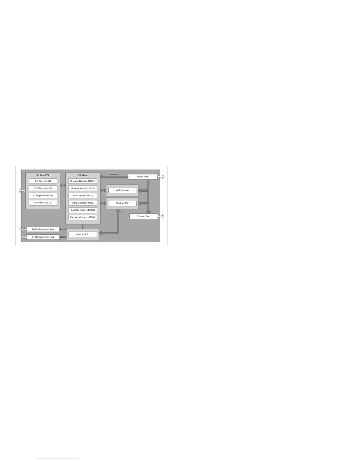
The 215U-2 module is made up of different interface areas with a
central input and output storage area (I/O store). The I/O store is
an area of memory made available for the status of the physical
on-board I/O and internal I/O registers. It also provides services for
other processes within the module.
The I/O store is split into eight different block types:
•
Two blocks made available for bit data (discrete)
•
Two blocks made available for word data (analog)
•
Two blocks made available for 32-bit words data (32-bit analogs)
•
Two blocks made available for floating point data (floats)
Each of these block types in turn support input and output locations
that can interface with the physical I/O on the local machine and
also be used for data storage when used as a gateway to external
devices. These block type locations are illustrated in Figure 1 and
are described in “Register memory map” on page 45. There are
other registers within the database that can be used for system
management.
Figure 1. Module structure
The radio and Ethernet interfaces (see Figure 1) allow the 215U-2
to communicate with other modules within the system using a
proprietary protocol called WIB. I/O Messages from other 215U-2
modules are received on the communication ports and then passed
to the I/O store which will in turn update the register locations
accordingly. The WIB protocol is designed to provide reliable
communications suitable for an Ethernet channel or for an open
license-free radio channel. It is an extremely efficient protocol
for radio communications because the messages are sent using
exception reporting (only transmitting when there is a change of
an input signal) rather than transmitting all of the time. Update
messages can also be configured at a predetermined time for
integrity checks.
Each message can be comprised of multiple I/O values, referred
to as a “block of I/O.” The messages use error checking and return
acknowledgment for greater reliability. Up to four attempts are made
when transmitting the message over each hop of the radio path,
and if no acknowledgment is received a Comms indication can be
flagged.
The on-board I/O includes eight discrete I/O, two single-ended
analog inputs, two differential analog inputs, and two current
sourcing analog outputs. Each discrete I/O can function as either
a discrete input (voltage-free contact input) or discrete output
(transistor output). Each I/O point is linked to separate I/O registers
within the I/O data store.
The following internal I/O can be accessed from the I/O store. The
inputs can be used to interpret the status of a single module or an
entire system:
•
Battery voltage—The battery terminal voltage, displayed as an
analog value.
•
Loop supply—The +24 Vdc analog loop supply (ALS) used to
power analog current loops, displayed as an analog value.
•
Expansion module volts—The supply voltage of the connected
expansion modules, displayed as an analog value.
•
RSSI—The radio signal level received from the upstream device,
reported as a dB level.
•
Comms Fail—A selectable register can indicate a
Communications Fail error for a particular message transmission.
The expansion port, allows 115S expansion I/O modules to be added
to the module. Expansion I/O is dynamically added to the internal I/O
of the 215U-2 module by adding an offset to the address.
Getting started
Most applications for the 215U-2 module require little configuration.
The 215U-2 has many sophisticated features, but if you do not
require these features you can use this section to configure the
units quickly.
To get started quickly:
1. Read “Installation” on page 3, which describes the power
supply, antenna/coax connections, and I/O connections.
2. Power on the 215U-2 module and set up a USB connection to
your PC. For detailed steps, see “Connecting to the device” on
page 12.
2
EATON www.eaton.com
Page 7
215U-2 802.11
wireless I/O and gateway
Installation
User Manual MN032EN
Effective October 2017
General
The 215U-2 Series modules are housed in a plastic enclosure with
DIN rail mounting, providing options for up to 14 I/O points, and
separate power and communications connectors. The enclosure
measures 7.2”x6.0”x1.3” (183mm x 156mm x 33mm), including
the connectors. The antenna protrudes from the top.
Power supply
SUP
BAT SUP
GND
+
B A
+
-
ETHERNET
USB RS232 SUPPLY
–
Optional
10.8–15 Vdc
Lead Acid
Battery
3A Fuse
+
+
-
15-30 Vdc
Supply
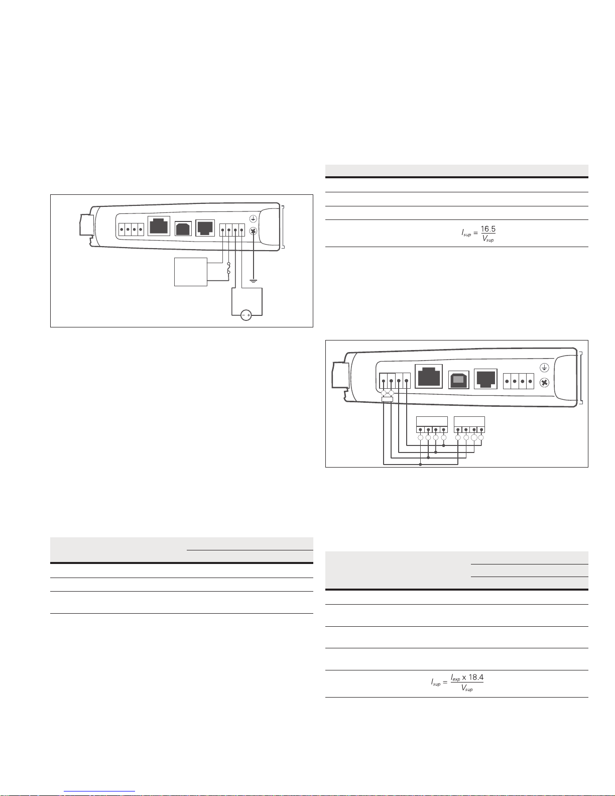
Figure 2. Supply connections
Powering from the SUP+ and SUP– terminals
The 215U-2 will operate from a 15–30 Vdc supply (nominal 24 Vdc)
connected to the SUP+ and SUP– terminals. The power supply must
be able to supply enough current to operate the device, to power all
of the I/O circuits, and to power the device’s radio transmitter when
it is sending data. A 24 Vdc 2.5 A power supply such as ELPRO
PSG60E or PS-DINAC-24DC-OK is suitable for all configurations,
including configurations requiring battery charging and expansion I/O.
If you need to use a supply with a lower power rating; or if you
need to power additional equipment in your installation; use these
guidelines to determine your required power supply current. Add
the relevant elements from Table 1 to determine your power supply
current requirement. Remember you also need to add current for
any other equipment being powered from the same power supply,
including relays, loop isolators, indicators, etc.
Table 1. Power supply current requirements
Supply voltage
17 Vd c 24 Vd c 30 Vdc
Base operating current 200 mA 150 m A 120 mA
Discrete I/O (per active input or output) 11 mA 7 mA 5 mA
Analog inputs and outputs
55 mA 38 mA 30 mA
(per 20 mA loop)
Connecting a back-up battery to the BAT+ and
GNDterminals
The 215U-2 provides an internal battery charger for Sealed Lead
Acid (SLA) batteries. You can connect a 13.8 V SLA battery to the
BAT+ and GND terminals to provide a backup power source if the
main supply fails. While the main supply is present, the battery will
charge at up to 0.5 A rate until the battery voltage reaches 14.3 V.
The battery charger will then maintain a float charge on the battery
at this voltage. To fully charge the SLA battery, the main supply must
be at least 17 Vdc.
When you connect a backup battery, you need to provide sufficient
power to support the additional charge current required when the
battery is discharged (when it is recovering from an extended power
interruption). Table 2 shows the additional current from your power
supply to support battery charging.
Table 2. Additional current to support battery charging
Supply voltage (V
) Current required (I
sup
)
sup
17 Vdc 1000 mA
24 Vdc 700 mA
30 Vdc 550 mA
Formula
Powering expansion I/O modules
The 215U-2 allows connection of 115S Series modules to the RS-485
port to provide expanded I/O capacity. You can use the “+” and
“–“ connections on the 215U-2 to provide up to 500 mA supply for
expansion I/O modules. If you have a back-up SLA battery connected
to the 215U-2, then this connection will also be powered from the
back-up supply, so that the expansion I/O modules receive the
backup power as well as the main module.
SUP
BAT SUP
GND
+
B A
B A
RS-485
+
-
ETHERNET
B A B A
USB RS232 SUPPLY
115S-xx 115S-xx
+
-
+
-
+
-
Figure 3. Expansion I/O power and RS-485
When the module is being powered from the main supply (SUP+
and SUP– terminals), you need to provide sufficient power to
support the additional current required by the expansion I/O
modules. Table 3 shows the additional current from yourpower
supply to support expansion I/O connection.
Table 3. Additional supply current to support expansion I/O
Expansion
I/O
current
(I
)
exp
Current required (I
Supply voltage
17 Vd c 24 Vdc 30 Vdc
)
sup
Base operating current 115S 120 mA 130 mA 90 mA 75 mA
Discrete inputs
13 mA 14 mA 10 mA 8 mA
(per active input)
Discrete outputs
25 mA 27 mA 20 mA 16 mA
(per active output)
Analog inputs and outputs
50 mA 55 mA 38 mA 30 mA
(per 20 mA loop)
Formula
Powering the module directly from the BAT+ and
GNDterminals
In some situations it may be desirable to power the module
directly from a 13.8 Vdc supply. This may be because this voltage
supply is already available at an installation or because the power
EATON www.eaton.com
3
Page 8
User Manual MN032EN
Effective October 2017
215U-2 802.11
wireless I/O and gateway
requirements for 115S modules are more than can be supplied by
the “+” and “–“ expansion I/O connections.
Use Table 4 to determine the device’s current requirements at
13.8 Vdc. Remember you also need to add current for any other
equipment being powered from the same power supply, including
relays, indicators, and any additional 115S modules.
Table 4. Current requirements
Supply current at 13.8 Vdc
Base operating current 230 mA
Discrete I/O (per active input or output) 10 mA
Analog inputs and outputs (per 20 mA loop) 50 mA
Internal I/O
The internal supply voltage register locations shown in the
following table can be monitored using the Diagnostics Web page
within the module’s Web-based configuration utility (see “Product
Reconfiguration” on page 36 for details). The values can also be
mapped to a register or an analog output on another module within
the network.
Table 5. Internal supply voltage registers
Register Description
30005 Local supply voltage (0–40 V scaling).
30006 Local 24 V loop voltage (0–40 V scaling). Internally generated
+24V supply used for analog loop supply. Maximum current
available is 100 mA.
30007 Local battery voltage (0– 40 V scaling).
30008 115S supply voltage (0–40 V scaling).
38005–38008 Floating point registers that display the actual supply voltage,
battery voltage, +24 V supply, and 115S supply. Note that these
are actual voltage values, whereas registers 30005 –30008
display a number between 8192 and 49152 that represents the
voltage scale 0–40 V.
To calculate the supply voltages from the register value use the
following calculation:
Volts = (Register Value) – 8192
1024
High and low voltage alarm indication may be configured for each of
these supply voltages. See "Analog inputs" on page 9 for details
on how to configure these alarms.
Grounding
To provide maximum surge and lightning protection each module
should be effectively earthed/grounded via a GND terminal on the
module. This is to ensure that the surge protection circuits inside the
module are effective. The module should be connected to the same
common ground point as the enclosure ground and the antenna
mast ground.
The 215U-2 has a dedicated earth/ground connection screw on the
bottom end plate next to the supply terminals. All earth/ground
wiring should be minimum 0.8in
2
(2 mm2), 14 AWG. If using the
215U-2 with serial expansion I/O modules, all expansion modules
must have a separate earth/ground connection from the front
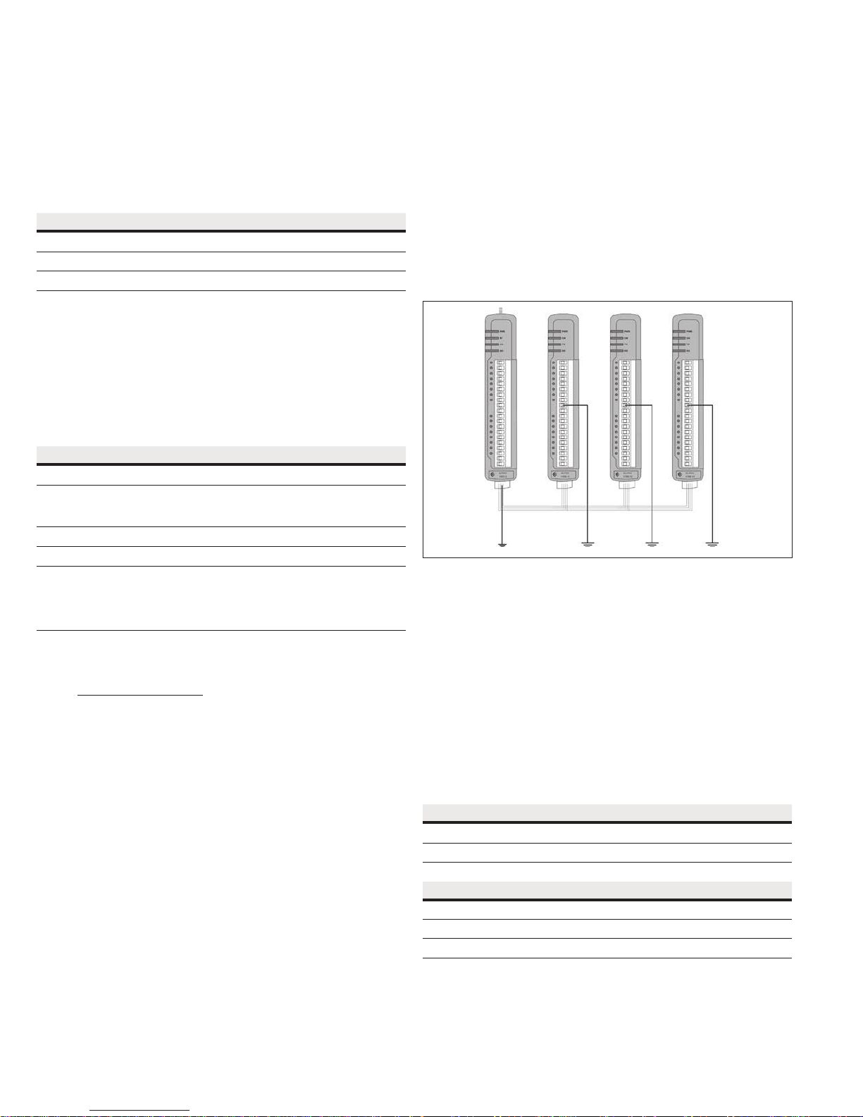
terminal back to the common earth or ground point. See Figure 4.
Figure 4. Grounding
Antennas
Antennas can be either connected directly to the module’s
RFconnector or connected via 50-ohm coaxial cable (such as
RG58Cellfoil or RG213) terminated with a male SMA coaxial
connector. The higher the antenna is mounted, the greater the
transmission range, but as the length of coaxial cable increases
sodo cable losses.
The net gain of an antenna and cable configuration is the gain of the
antenna (in dBi) less the loss in the coaxial cable (in dB). Maximum
net gain for the 215U-2 will depend on the licensing regulation for
the country of operation and the operating frequency.
Typical antennas gains and losses are:
4
EATON www.eaton.com
Table 6. Typical antennas gains and losses
Antenna Gain (dBi)
Dipole 2 dBi
Collinear 5 or 8 dBi
Directional (Yagi) 6–15 dBi
Cable type Loss at 2.4GHz
RG58 cellfoil cable kits (3 m,10 m, 20 m) -1.8dB, -6dB, -12dB
RG213 per 10 m (33 ft) -4dB
LDF4 -50 per 10 m (33 ft) -2.2dB
The net gain of the antenna and cable configuration is determined
by adding the antenna gain and the cable loss. For example, an 8 dBi
antenna with 10 meters of Cellfoil (–6 dB) has a net gain of 2 dB
(8 dB – 6 dB).
Page 9
215U-2 802.11
wireless I/O and gateway
User Manual MN032EN
Effective October 2017
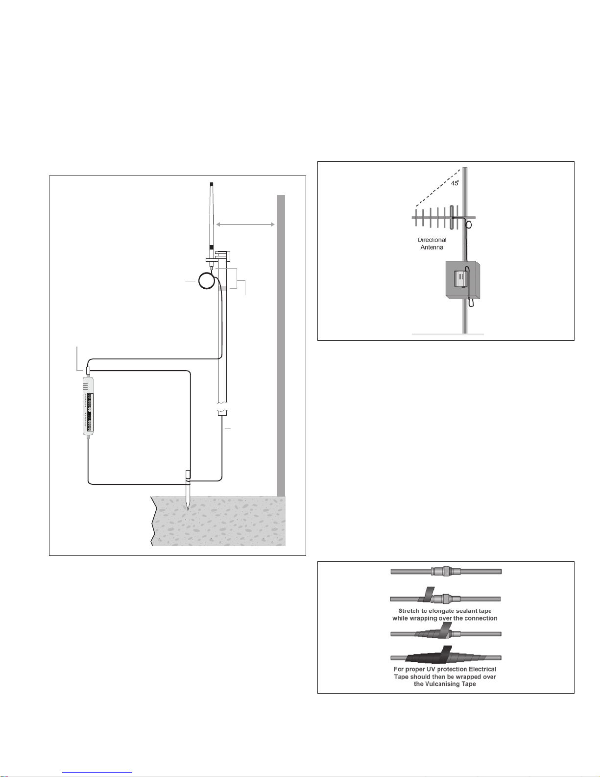
Dipole and Collinear antennas
Dipole and collinear antennas transmit the same amount of radio
power in all directions, and are easy to install and use because they
do not need to be aligned to the destination. The dipole antenna
does not require any additional coaxial cable. However, a cable must
be added if using any of the other collinear or directional antennas.
In order to obtain the maximum range, collinear and dipole antennas
should be mounted vertically, preferably at least one wavelength
away (see Figure 8 for distances) from a wall or mast and at least
3ft (1 m) from the radio module.
Stress
Relief
Loop
Antenna
*
1 Wavelength
(minimum)
Weatherproof
Connections
(recommended:
3M™ 23 selfbonding tape)
Wavelength:
2.4GHz: 5inch (12.5cm)
Surge Arrestor
(recommended)
Coaxial Cable
Directional radomes should be installed with the central beam
horizontal, and must be pointed exactly in the direction of
transmission to benefit from the gain of the antenna.
Parabolic antennas should be mounted according to the
manufacturer’s instructions, with the parabolic grid at the back and
the radiating element pointing in the direction of the transmission.
Ensure that the antenna mounting bracket is well connected
to ground.
Figure 6. Directional antenna
GND
215U-2
GND
at least 11 AWG (4 mm2)
Provide good ground
connection to mast,
module, and surge
arrestor.
If ground conditions
are poor, use more
than one stake.
Earth Stake
Mast
Earth Conductor
at least 5 AWG
(16 mm2)
For maximum
*
range, install
above local
obstructions.
Figure 5. Antennas installation—Collinear/Dipole
Directional antennas
A directional antenna provides high gain in the forward direction,
but lower gain in other directions. This type of antenna may be used
to compensate for coaxial cable loss for installations with marginal
radio path. Directional antennas can be any of the following:
•
Yagi antenna with a main beam and orthogonal elements
•
Directional radome, which is cylindrical in shape
•
Parabolic antenna
Yagi antennas should be installed with the main beam horizontal,
pointing in the forward direction. If the Yagi antenna is transmitting
to a vertically mounted omni-directional antenna, the Yagi elements
should be vertical. If the Yagi is transmitting to another Yagi, the
elements at each end of the wireless link need to be in the same
plane (horizontal or vertical).
Installation tips
Connections between the antenna and the coaxial cable should
be carefully taped to prevent ingress of moisture. Moisture
ingress in the coaxial cable is a common cause for problems with
radio systems because it greatly increases the radio losses. We
recommend that the connection be taped—first with a layer of PVC
tape, next with vulcanizing tape (such as 3M™ 23 tape), and finally
with another layer of PVC UV-stabilized insulating tape. The first layer
of tape allows the joint to be easily inspected when troubleshooting
because the vulcanizing seal can be easily removed (see Figure 10).
Where antennas are mounted on elevated masts, the masts should
be effectively grounded to avoid lightning surges. For high lightning
risk areas, approved ELPRO surge suppression devices, should be
fitted between the module and the antenna. The surge supression
must have a “turn on” voltage of between 10 and 20V. If the antenna
is not already shielded from lightning strike by an adjacent grounded
structure, a lightning rod may be installed above the antenna to
provide shielding.
Figure 7. Vulcanizing tape
EATON www.eaton.com
5
Page 10
User Manual MN032EN
Effective October 2017
Connections
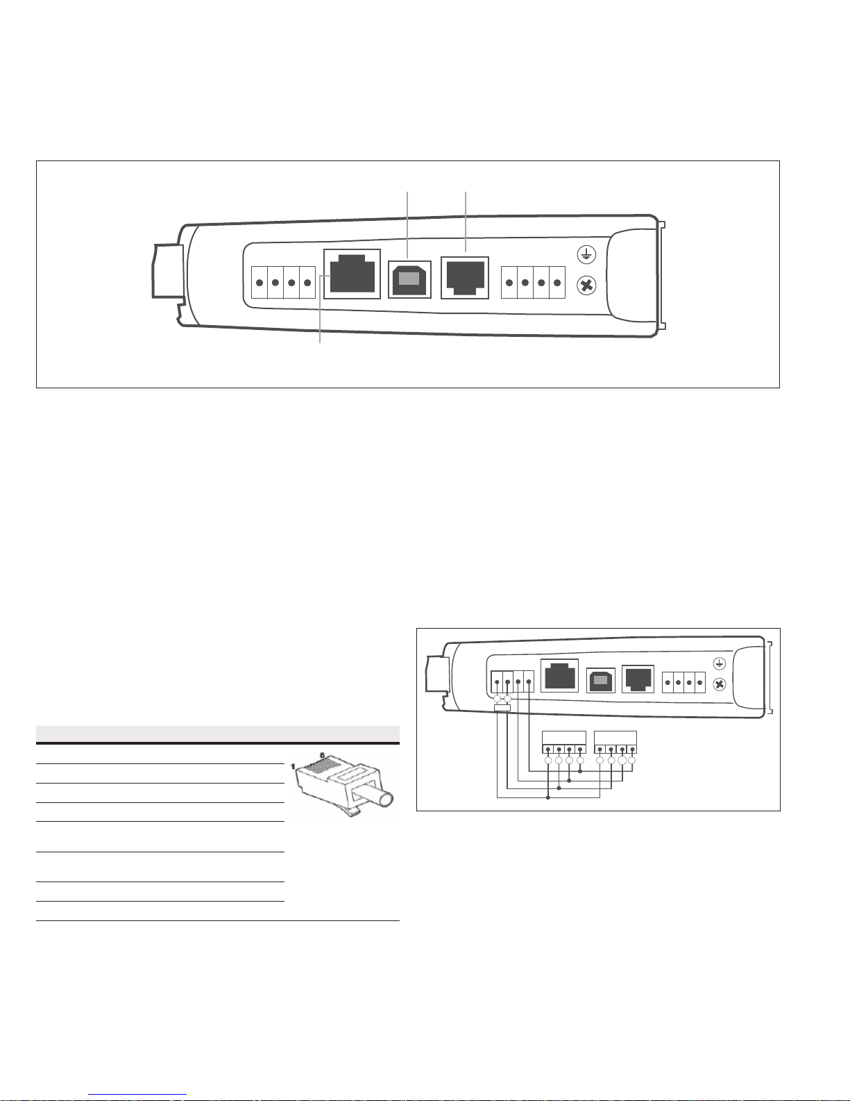
Bottom panel connections
Figure 8. Bottom panel connections
USB Port RS-232 Port
B A
+
-
ETHERNET USB RS232 SUPPLY
RJ-45 Ethernet Port
(connects to hub or switch)
GND
BAT SUP
+
215U-2 802.11
wireless I/O and gateway
SUP
+
-
Ethernet port
The 215U-2 modules provides a standard RJ-45 Ethernet port
compliant to IEEE 802.3 10/100Base-T. This port provides full
access to the module, including configuration, diagnostics, log file
download, and firmware upload of both the local and remote units.
Additionally, the Ethernet port can provide network connectivity for
locally connected third-party devices with Ethernet functionality.
USB device port for configuration
The 215U-2 module also provides a USB device (USB-B) connector.
This connector provides configuration of the device and remote
configuration access to other devices in the radio network.
RS-232 port
The 215U-2 module provides an RS-232 serial port that supports
operation at data rates up to 230,400 baud. This port supports
Modbus protocol. The RS-232 port is accessed using an RJ-45
connector wired as a DCE according to the EIA-562 Electrical
Standard.
Table 7. RJ-45 connector
RJ-45 Signal Required Signal name Connector
1 RI — Ring Indicator
2 DCD — Data Carrier Detect
3 DTR Y Data Terminal Ready
4 GND Y Signal Common
5 RXD Y Receive Data
(frommodule)
6 TXD Y Transmit Data
(tomodule)
7 CTS — Clear to Send
8 RTS — Request to Send
RS-485 port with Modbus support
The 215U-2 module provides an RS-485 serial port that supports
operations at data rates up to 230,400 baud. The default baud rate is
9600 baud, no parity, 8 data bits and 1 stop bit, which matches the
115S serial expansion module default settings. This port supports the
Modbus protocol.
The RS-485 port terminal is hosted on the four-way expansion
connector on the bottom edge of the module. An on-board RS-485
termination resistor provides line termination for long runs. As a
general rule, termination resistors should be enabled at each end
of the RS-485 cable. When using 115S expansion I/O modules,
remember to enable the RS-485 termination resistor switch that is
located on the end module.
SUP
BAT SUP
GND
+
B A
B A
RS-485
+
-
ETHERNET
B A B A
USB RS232 SUPPLY
115S-xx 115S-xx
+
-
+
-
+
-
Figure 9. RS-485 connections
6
EATON www.eaton.com
Page 11
215U-2 802.11
wireless I/O and gateway
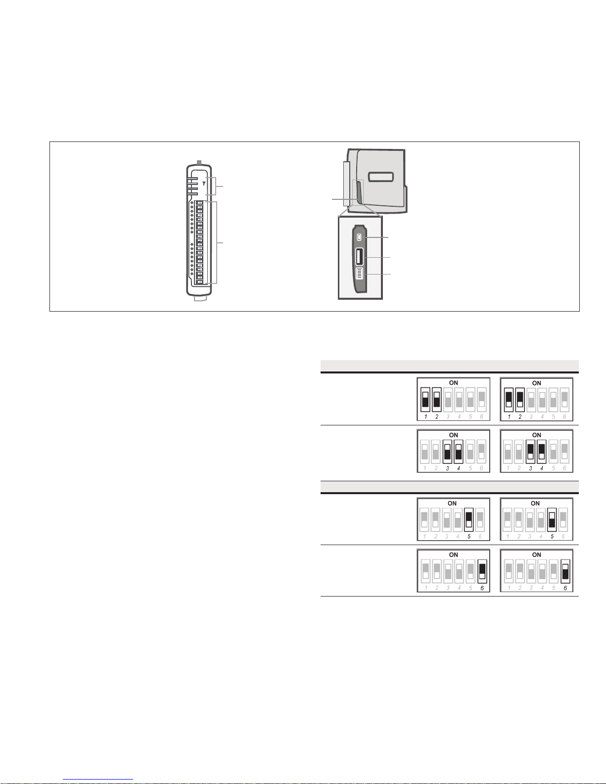
Side access configuration panel
A small access panel on the side of the module hides a factory boot
switch, USB host port, and a small bank of DIPswitches that are
used for analog input voltage and current selection, external boot,
and default configuration settings. Use a screw-driver to free the
latch to open the access panel.
PWR
RF
LED Indicator Lights
232
485
User Manual MN032EN
Effective October 2017
Side
Access
Panel
I/O Connectors
Figure 10. Access panel
Factory boot switch
The factory boot switch is used for factory setup and diagnostics.
This switch should only be used if advised by ELPRO technical
support.
USB host port
This port is a USB host (master port) that can interface with
USB storage devices for upgrading the module firmware and for
uploading logged data files. For details, see“To perform a full
firmware upgrade using USB flash drive” on page 53. Also see
“Data logging” on page 38.
DIP switches
The DIP switches are used to select a number of functions within
the module, as shown in the following table.
•
DIP switches 1 to 2—Used for measuring current or voltage
onanalog input 3. Set DIP switches to “on” to measure current
(0–20 mA) and “off” for voltage (0–5 Vdc).
•
DIP switches 3 to 4—Used for measuring current or voltage
onanalog input 4. Set DIP switches to “on” to measure current
(0–20 mA) and “off” for voltage (0–5 Vdc).
•
DIP switch 5—Not used.
•
DIP switch 6—When set to “on” (enabled) and the module is
restarted, the module boots up with a known factory default
configuration, including a default IP address for the Ethernet
connection. See “Connecting to the module” on page 13.
ote:N When DIP switch 6 is “on,” radio and I/O functionality isdisabled.
Factory Boot
Switch
USB Host
Conguration
Switches
Table 8. Switch functions
Switch Function Current Voltage
DIP 1 and 2 Analog
input 3
DIP 3 and 4 Analog
input 4
Switch Function Disabled Enabled
DIP 5 Not used
DIP 6 Setup mode
EATON www.eaton.com
7
Page 12
User Manual MN032EN
Effective October 2017
215U-2 802.11
wireless I/O and gateway
Front panel connections
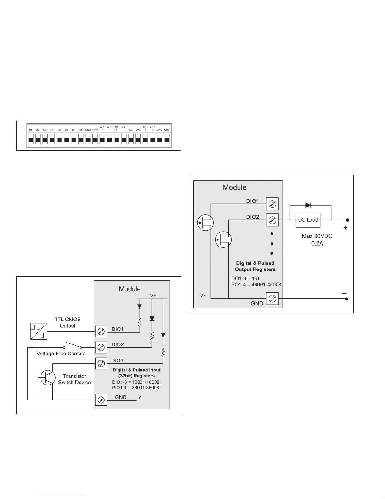
The front panel on the 215U-2 module provides connections for the
following:
•
Eight digital input/output (DIO 1–8)
•
Two 12-bit, 0.1% accuracy differential analog inputs
•
Two single-ended 12-bit, 0.1% accuracy analog inputs
•
Two 13-bit, 0.1% accuracy current sourcing analog outputs
•
Connection terminals for common and +24 V analog loop supply
(ALS); maximum ALS current limit is 100 mA
Figure 11. Front panel connections
Digital or pulsed inputs
Each digital I/O channel on the 215U-2 module can act as either
an input or an output. The input/output direction is automatically
determined by the connections and configuration of the I/O. If you
have an I/O channel wired as an input but operate the channel as an
output, no electrical damage will occur but the I/O system will not
operate correctly. If you are operating the channel as an output and
you read the corresponding input value, it will indicate the status of
the output.
Marked D1–8, the digital inputs share the same terminals as the
digital outputs on the 215U-2 module. A digital input is activated by
connecting the input terminal to GND or common, either by voltagefree contact, TTL level, or transistor switch. Each digital input has
an orange indication LED that will turn on when the input has been
connected to a GND.
Digital inputs 1–4 can be used as pulsed inputs. The maximum pulse
frequency is 50 kHz for input 1 and 2, and 1kHz for input 3 and 4.
Digital/pulsed inputs are suitable for TTL signal level, NPN-transistor
switch devices, or voltage-free contacts (a relay or switch with
debounce capacitor).
Frequencies greater than 1 kHz need to use a TTL logic drive or an
external pull-up resistor (1 KΩ to V+). Pulsed inputs are converted
to two different values internally. The first value is the pulse count,
which is an indication of how many times the input has changed
state over a configured time period. The second value is a pulse
rate, which is an analog input derived from the pulse frequency.
Forexample, 0 Hz = 4 mA and 1 kHz = 20 mA.
All pulsed input counts are stored in non-volatile memory, so thatthe
values are saved in the event of a power failure or a modulereset.
Digital outputs (pulsed outputs)
Digital outputs are open-collector transistors, and are able to switch
loads up to 30 Vdc, 200 mA. The eight digital outputs sharethe
same terminals as the digital input. These terminals aremarked D1–8.
Figure 12. Digital/pulsed input wiring
8
EATON www.eaton.com
Figure 13. Digital pulsed output wiring
When active, the digital outputs provide a transistor switch to
EARTH (Common). To connect a digital output, see Figure 13. A
bypass diode (IN4004) is recommended to protect against switching
surges for inductive loads such as relay coils. The digital channels
D1–4 on the 215U-2 module can be used as pulse outputs with a
maximum output frequency of 10 kHz.
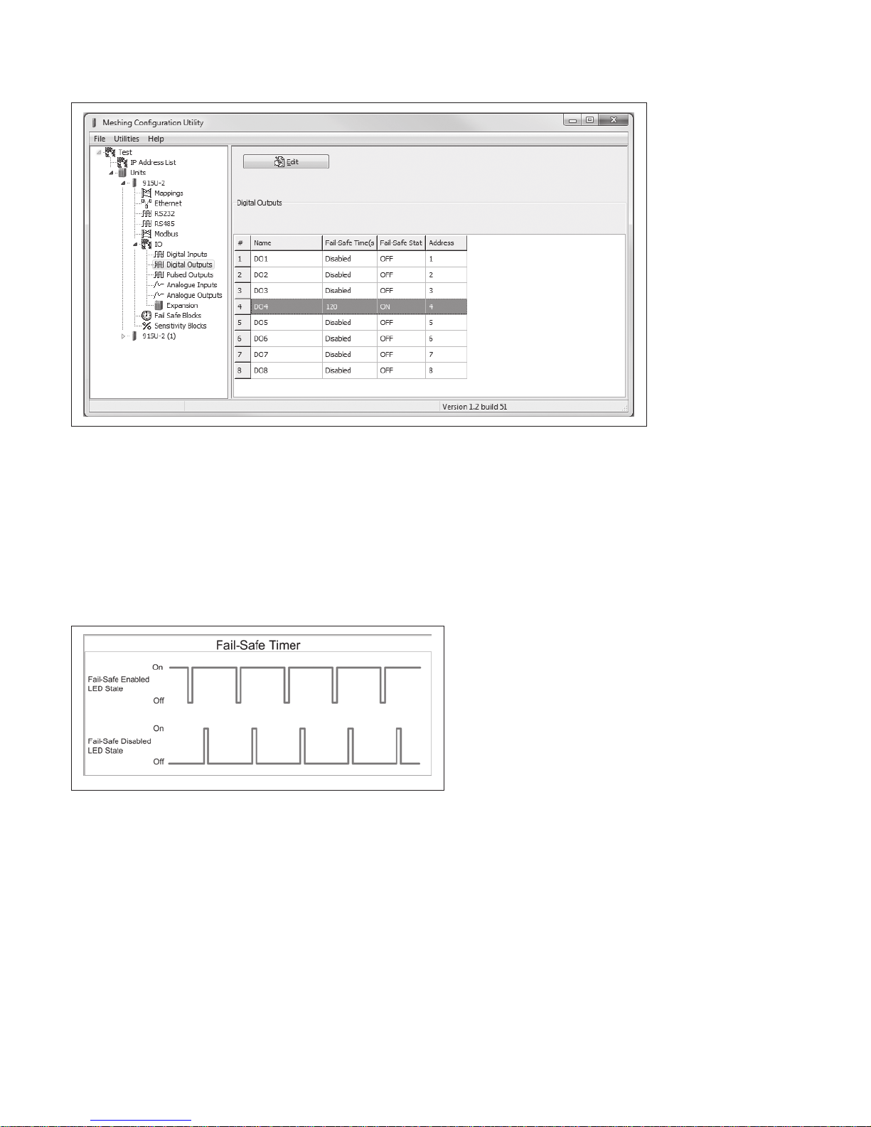
Digital output fail-safe status
In addition to indicating the digital output status (on or off), the LEDs
can also indicate a communications failure by flashing the output
LED. This feature can be used by configuring a fail-safe time and
status via the I/O Digital Output screen in the MConfig utility.
Page 13
215U-2 802.11
wireless I/O and gateway
Figure 14. Digital output fail-safe times
User Manual MN032EN
Effective October 2017
The fail-safe time is the time the output counts down before
activating a fail-safe state. Normally this would be configured for a
little more than twice the update time of the mapping that is sending
data to it. This is because the fail-safe timer is restarted whenever
it receives an update. If you send two successive updates and fail
to receive both of these messages, the timer counts down to zero
and activates the fail-safe state. If the fail-safe state is enabled (on),
the LED flashes briefly off and the digital output turns on. If the failsafe state is disabled (off), the LED flashes briefly on and the digital
output turns off.
Figure 15. Fail-safe state
Analog inputs
The 215U-2 module provides two floating differential analog inputs
and two grounded single-ended analog inputs. Analog inputs 1 and
2 will automatically measure current (0–20 mA) or voltage (0–25V),
depending on what is connected to the input. Analog inputs 3 and 4
must be configured to measure current (0–20 mA) or voltage (0–5V)
via the DIP switches on the configuration panel (see “Side access
configuration panel” on page 7).
An internal 24 V analog loop supply (ALS) provides power for any
current loops with a maximum current limit of 100mA. The LEDs
have an analog diagnostic function and will indicate the status of the
input. The LED comes ON when any analog signal is detected, and
will go OFF when the analog signal drops to zero.
ote:N By default, there is a one-second delay on the input because of the
filter. Filter times can be changed using the Analog Input screen within the
MConfig utility. For more information, see "Analog inputs" on page 9.
The LEDs next to AI1+, AI2+ indicate the current on these inputs.
The LEDs next to AI1– and AI2– indicate the voltage on the
analog inputs.
EATON www.eaton.com
9
Page 14
User Manual MN032EN
Effective October 2017
215U-2 802.11
wireless I/O and gateway
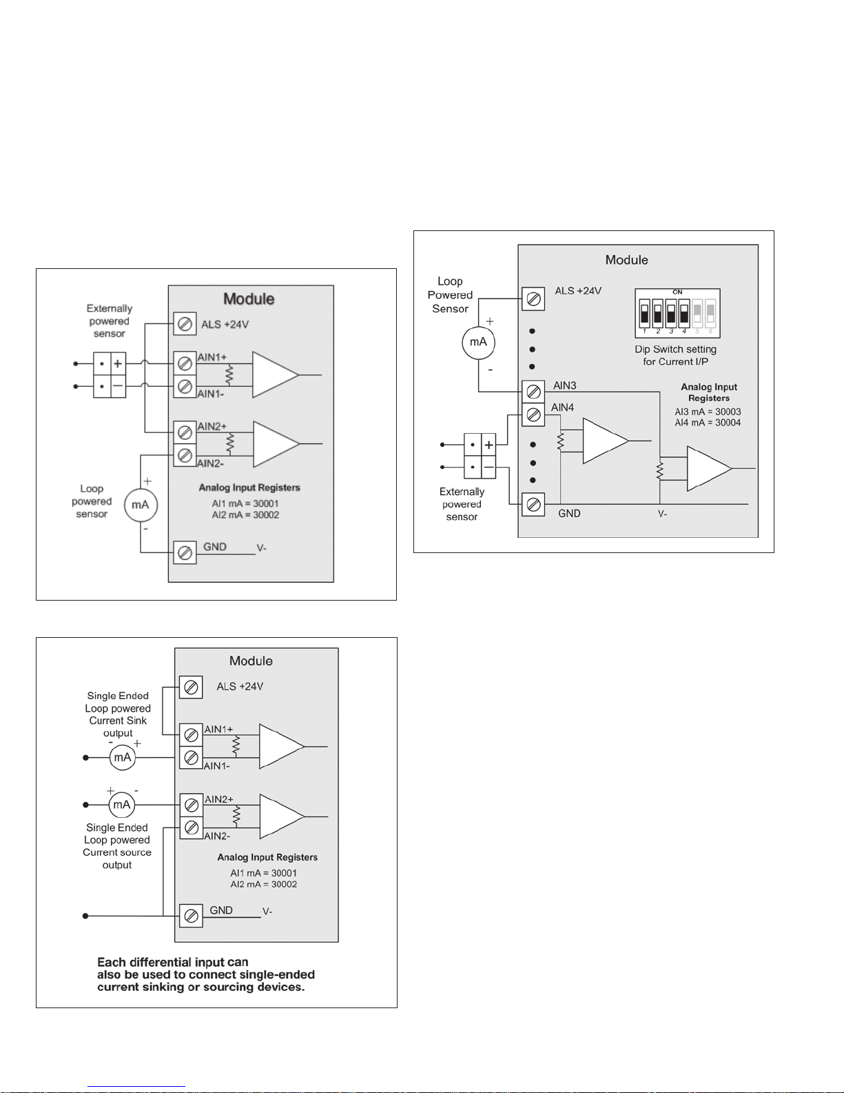
Differential current inputs
Only analog input 1 and 2 can be wired as differential Inputs.
Differential mode current inputs should be used when measuring a
current loop, which cannot be connected to ground. This allows the
input to be connected anywhere in the current loop. Common mode
voltage can be up to 27 Vdc.
Figure 16 indicates how to connect loop-powered or externally
powered devices to the 215U-2 differential analog inputs. It should
also be noted that the differential inputs can also be used to connect
single-ended current sinking or current sourcing devices. Figure 18
shows how to connect to these types of devices.
Single-ended current input mode is useful if the sensor loop is
grounded to the 215U-2 module. Devices can be powered from the
24V analog loop supply (ALS) generated internally from the module.
The DIP switches (located in the side access panel) are used to
determine if the inputs will be current or voltage. DIP switches 1
and 2 are used for analog 3, and DIP switches 3 and 4 are used for
analog 4. For current, set both DIP switches to the “on” position.
Forvoltage, set both to “off.”
Figure 16. Differential current inputs (AI1 and AI2)
Figure 18. Al3 and Al4 Single-ended current inputs
Voltage inputs
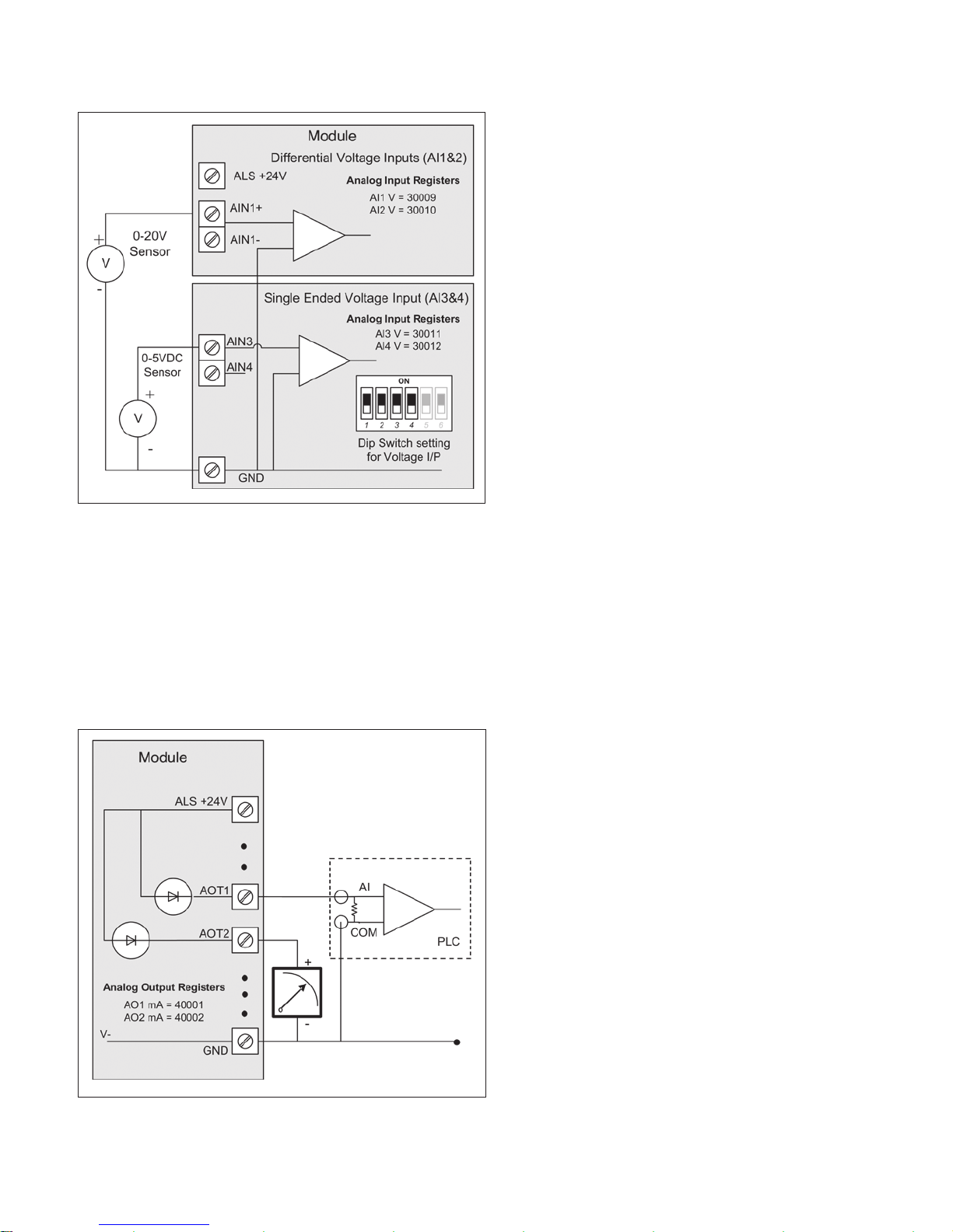
All analog inputs can be set up to read voltage. If using analog input
1 and 2, connect the voltage source across the positive terminal of
the input and ground. If using analog input 3 and 4, connect across
the input terminal and GND.
ote:N Default scaling gives 0–20 V for 0–20 mA output on analog 1 and 2.
Default scaling for analog 3and4 gives 0–5 V for 0–20mA output. For voltage
input on analog 3 and 4, set both DIP switches to the OFF position.
Figure 17. Al1 and Al2 single-ended current inputs
10
EATON www.eaton.com
Page 15
215U-2 802.11
wireless I/O and gateway
Figure 19. Single-ended voltage inputs
Analog outputs
The 215U-2 module provides two 0–24 mA DC analog outputs for
connecting to analog inputs on equipment (such as PLCs, DCS, and
loggers) or connecting to instrument indicators for displaying remote
analog measurements. The 215U-2 analog outputs are a sourcing
output and should be connected from the analog output terminal
through the device or indicator to ground (GND). See Figure 20 for
connections. The LEDs provide level indication depending on current.
The LEDs appear dimmed for 4 mA and bright for 20 mA.
User Manual MN032EN
Effective October 2017
System design
Design for failures
All well-designed systems consider system failure. I/O systems
operating on a wire link will fail eventually. Failures can be shortterm, such as interference on the radio channel or power supply
failure, or long-term, such as equipment failure.
The modules provide the following features for system failure:
•
Outputs can reset if they do not receive a message within a
configured time. If an output should receive an update or change
message every 10 minutes and it has not received a message
within this time, some form of failure is likely. If the output
is controlling machinery, it is good design to switch off the
equipment until communications are re-established.
•
The modules provide a fail-safe feature for outputs. This is a
configurable time value for each output. If a message has not
been received for this output within the configured time, the
output will assume a configured value. We suggest that this reset
time be a little more than twice the update time of the input. It
is possible to miss one update message because of short-term
interference. However, if two successive update messages are
missed, long term failure is likely and the output should be reset.
For example, if the input update time is three minutes, set the
output reset time to seven minutes.
•
A module can provide an output that activates on communication
failure to another module. This can be used to provide an external
alarm indicating that there is a system fault.
Testing and commissioning
We recommend that the system is fully bench tested before
installation. It is much easier to find configuration problems on
the bench when the modules are next to each other as opposed
to being miles apart. When the system is configured and you are
confident that it works, back up the configurations of all modules.
Figure 20. Analog outputs
EATON www.eaton.com
11
Page 16
User Manual MN032EN
Effective October 2017
Connecting to the device
To configure the 215U-2 you connect to it using a web browser on
your PC or mobile device.
Connecting to the module for the first time
On first connection, you can only connect to the device through
its USB port. Once you have connected to the device for the first
time, you can enable access through the Ethernet port and remotely
through the 802.11 Wireless port.
ote:N Before enabling the Ethernet Port or Wireless port for Configuration
access, read the section “Device Security”.
Connecting to the device’s USB port
The USB port is located on the bottom side of the module. (Refer
Figure 11 “Bottom Panel Connections”). To connect, you need an
USB cable (USB-A to USB-B) for connecting from your computer to
the module’s USB-B port.
If this is the first time you have used your computer to connect
to an ELPRO device through the USB port, then you will need to
download the USB driver file from the product’s internet website.
This is available from the same location that you downloaded this
user manual.
You will also need to know the username/password configured for
the device. If the module is new out-of-the-box you can use the
default settings. Otherwise, you may need to restore these settings.
If you have lost the password, you can set the username and
password back to the default values. For instructions, see “Restoring
the factory default connection settings” on page 42.
1. Install the USB Device driver to your PC. You do this by running
the installer ".exe" file and following the prompts.
2. Power on the device, and wait for the device to finish booting
and for the “PWR” LED to go solid green (about 1 minute).
3. Plug in the USB cable and wait for your computer to recognize
the new USB device.
4. Once the device is connected, you will have an additional
Network Adapter in your device manager list
“Elpro 215U-2 USB Ethernet/ RNDIS Interface”
5. Open your web browser (recommended Internet Explorer
version 10 or later) and type “http://192.168.111.1” into the
browser bar. The device’s USB address is always the same.
The module responds with a username and password box.
6. Type the username and password. The default username is
“user” and the default password is “user”.
215U-2 802.11
wireless I/O and gateway
The module’s default settings are as follows:
IP Address 192.168.0.1XX
(shown on the printed label on the side of
the module)
Subnet Mask 255.255.255.0
User Name user
Password user
ote:N You cannot access the device through Ethernet until remote access
has been enabled. The first time you access the device, you need to use the
USB method described above. Then you can enable remote access on the
quick start configuration page.
Once you have the device’s IP address and password:
1. Connect an Ethernet cable between the module’s Ethernet port
and the PC.
2. Configure your PC networking settings to be on the same
network as the device. For instructions on how to do this, see
“Configuring PC networking settings for Ethernet and Wireless”
on page 42.
3. Open your web browser (recommended Internet Explorer
version 10 or later) and type “http://” followed by the IP address
of the module and press Enter.
The module responds with a username and password box.
If the module does not respond, check that you have configured
your PC according to the section “Configuring PC networking
settings for Ethernet and Wireless” on page 42.
4. Type the username and password. The default username is
“user” and the default password is “user”.
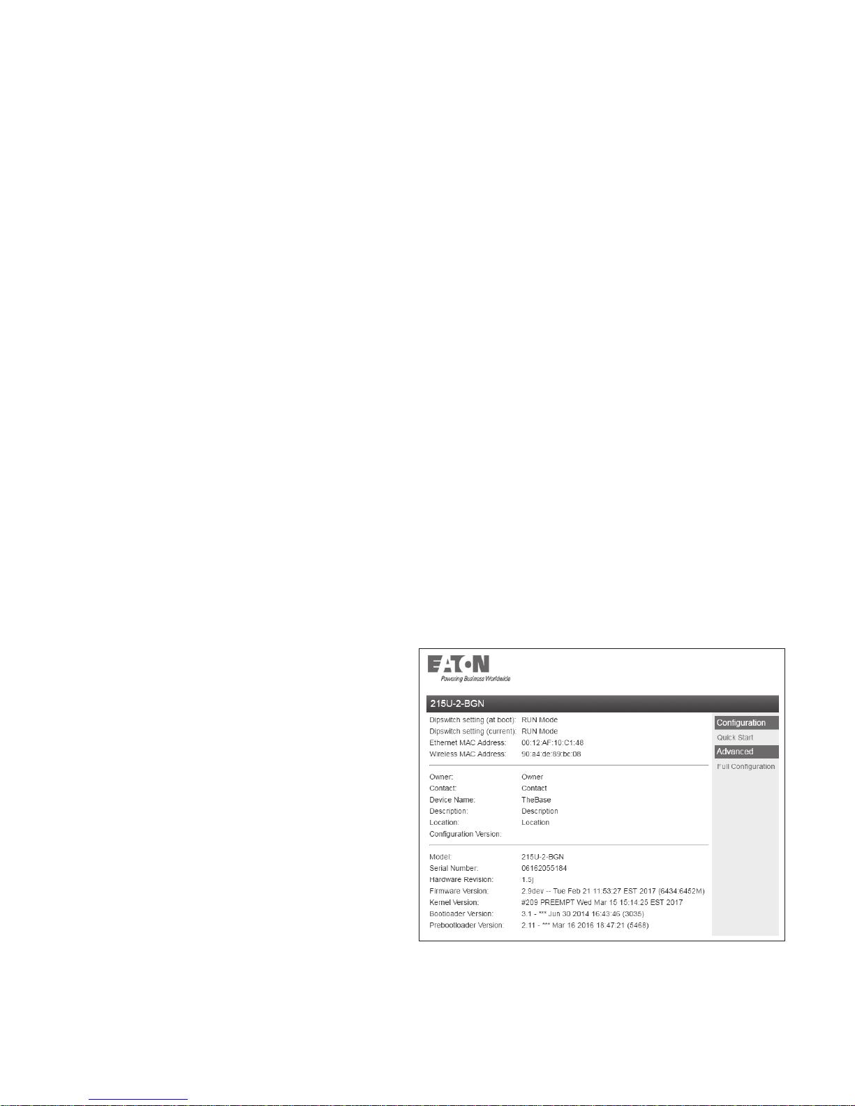
This connects you to the home page of the Web-based configuration
utility (see Figure 21). This utility allows you to manage wireless
connection links between all modules in the system through a
standard browser, such as Microsoft
®
Internet Explorer®.
This connects you to the home page of the Web-based configuration
utility (see Figure 21). This utility allows you to manage wireless
connection links between all modules in the system through a
standard browser, such as Microsoft
®
Internet Explorer®.
Connecting to the Device’s Ethernet port
The Ethernet port is located on the bottom side of the module.
(Refer Figure 8 “Bottom Panel Connections”). To connect, you need
an Ethernet cable for connecting to the module’s Ethernet port.
You also need to know the device’s IP Address and the username/
password configured for the device.
12
EATON www.eaton.com
Figure 21. Device home page
Page 17
215U-2 802.11
wireless I/O and gateway
User Manual MN032EN
Effective October 2017
Device Security
The 215U-2 supports industrial protocols such as Modbus and WIB
that do not provide encryption or authentication. These protocols are
convenient to use as they are widely known and supported by an
extensive range of equipment.
The downside of using these protocols is that they are also
vulnerable to a variety of cyber-attacks, so you must consider the
security of the networks that they operate over.
As a precaution, these protocols are disabled in the default
configuration. Before enabling any of these protocols, you should
ensure that the following precautions are in place.
•
Change the device’s access password from the default (“user”).
•
Make sure that any network connected to the device’s Ethernet
port is secured from outside access. If an internet connection is
present, ensure it is effectively firewalled.
•
Secure the radio network using WPA-PSK encryption.
•
Ensure that the radio network encryption passphrase is long (at
least 20 characters) and complex. Quality of security assurance
offered depends on the complexity of this passphrase. Short
and simple passphrases can easily be compromised by skilled
attackers.
•
Ensure that knowledge of the radio network encryption
passphrase is kept to a limited number of workers and ensure the
access password and radio passphrase are changed whenever
any of these workers' security status changes.
•
Ensure physical security of the devices connected to the network.
•
In the event that a device is lost or stolen, ensure that the
encryption key used to secure communications on the radio
network is changed.
Peer-to-Peer I/O mapping, Serial port configuration, Data Logging,
Advanced networking configuration, diagnostics, and User
management. These pages are described later in this manual.
•
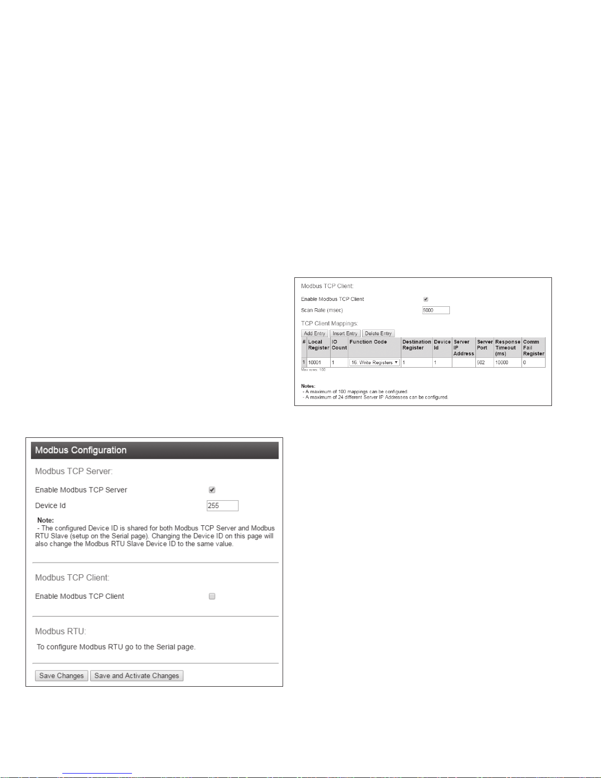
If your system is based on Modbus TCP protocol, you need to
enable Modbus TCP Server by selecting Full Configuration >>
Modbus TCP and checking "Enable Modbus TCP Server". Once
you have the device configured, you will be able to access it using
a Modbus TCP client (Master) at the IP address you configure.
ote:N Before navigating away from this page, you need to click the “Save
Changes” or “Save Changes and Reset” button at the bottom of the page.
Otherwise your changes will be lost.
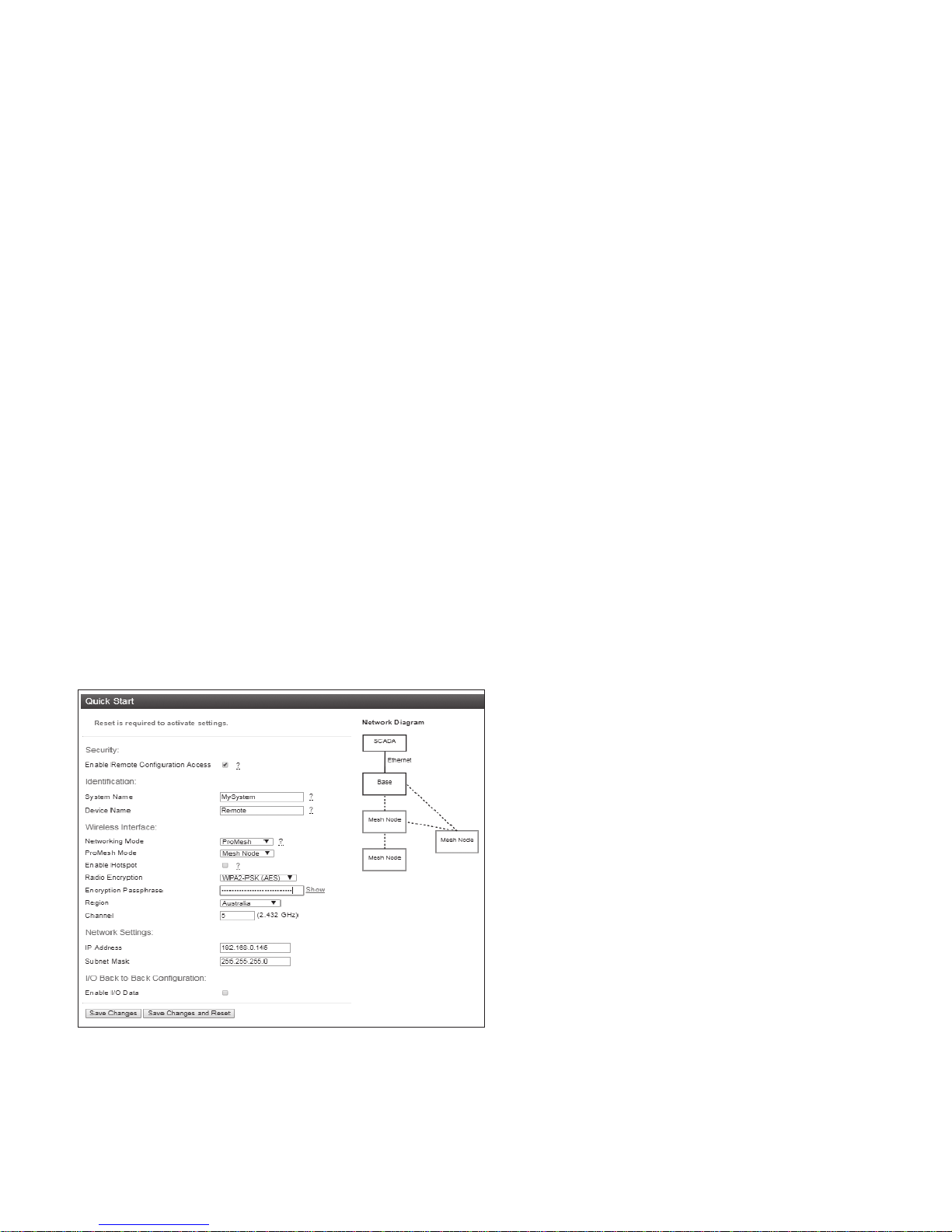
Security
Enable Remote Configuration Access: Select this to enable access
to the device configuration and the dashboard web pages through
Ethernet or Wireless interfaces. If this is not selected, you can only
access the device web pages through the USB connection.
Identification
System Name: All devices in a system are configured with a
common system name. This is used in ProMesh mode as a common
network ID for all devices to connect.
Device Name: Each device in the system should be configured
with a unique device name. This name is used to identify devices in
diagnostic display (Connectivity) and is used in Fixed Link mode as
the device ID for other devices to connect to.
Quick start conguration
Access the quick start configuration by clicking on the “Quick Start”
text on the right side menu under “Configuration”.
Figure 22. Quick start
•
For the majority of installations, you will only need to access
this Quick Start page. This configuration will get your devices
connected and communicating. You can then connect remotely if
you need to configure other functionality.
•
Click “Full Configuration” to access advanced configuration pages.
These pages provide access to additional functionality including
EATON www.eaton.com
13
Page 18

User Manual MN032EN
Effective October 2017
215U-2 802.11
wireless I/O and gateway
Wireless Interface
Networking Mode: You can choose one of three networking modes
depending on your system requirements:
•
Manual Mode implements traditional 802.11 networking
configuration. You configure units as Access Point or Client. Client
units connect to an Access Point with matching SSID (System
Address).
•
ProMesh Mode implements automatic repeater configuration,
where devices (Mesh Node) automatically choose and maintain
the best path back to a central station (Base). All devices in the
network use a common SSID (System Name).
•
Fixed Links Mode implements a fixed repeater configuration
where field devices (Remote) are configured to connect directly or
via intermediate sites (Repeater) to a central station (Base).
802.11 Mode: This option is available when the Networking mode
is set to Manual. A traditional 802.11 network has a single Access
Point and one or more Clients.
•
System Address (ESSID): This is the “Extended Service Set
Identification” used in 802.11 mode. For a client to connect, the
client needs to have this set to the same value configured on the
Access Point.
ProMesh Mode: This option is available when the Networking Mode
is set to ProMesh. A ProMesh network consists of a single central
station (Base), and one or more remote sites (Mesh Nodes) which
can each operate as a repeater for other stations.
The Mesh Nodes select the best path to the Base depending on
the number of hops to the base, and based on signal strength of
the hops in the path. Once connected, the Mesh Nodes monitor
the path quality and will swap to use a better path if one comes
available.
All devices in a ProMesh network share the same SSID (the
configured “System Name”).
•
Enable Hotspot: This option is only available for Mesh Nodes
in a ProMesh network. Because the ProMesh is designed to
be flexible, the Mesh Nodes devices may not always advertise
for a connection. If you want to be able to connect from a non
ProMesh device to one of the Mesh Nodes, then select this
option on that Mesh Node to ensure it remains available for
connection.
Device Mode: This option is available when the Networking mode
is set to “Fixed Links”. A Fixed Link network consists of a central
station (Base) accessing a fixed arrangement of repeater stations
(Repeater) and remote stations (Remote). All devices ultimately
connect to the central station (Base). Repeaters and remotes can
either connect directly to the base, or connect using additional
repeater stations to extend the radio range.
•
Upstream Device Name: When the Device Mode is “Repeater”
or “Remote”, you need to select the Upstream device. When
the connection is direct to the base, this is the Device Name
of the base station. When the connection is via repeaters, this
is the name of the repeater station that is used to reach the
base station.
Radio Encryption: Select the desired Encryption mode. Normally
this should be WPA2-PSK (AES), which is the strongest encryption
available. Only select other modes if you need to do this to connect
to a third party or legacy system that does not support WPA2
protocol.
ote:N Selecting Encryption “None” or “WEP” makes your network vulnerable
to attack. This product makes use of standard 802.11 physical signaling, so
without encryption there is no protection from attackers with off-the-shelf
hardware. Selecting WEP provides very limited protection from attack. WEP
protocol has known weaknesses that make it relatively simple to penetrate.
Encryption Passphrase: This is the secret key for your network
encryption. All devices in the network need the same passphrase to
communicate.
ote:N For best security, this passphrase must be long (at least 20 characters)
and should not include text that could be guessed such as names, dates, etc.
ote:N Always keep this passphrase private, and ensure that the system
configuration is updated with a new passphrase if this key becomes
compromised.
Region: The module is configured from the factory to allow
operation globally. To take advantage of additional radio channels
and higher allowed power in some countries, you can select a
different region. The power is automatically set to the maximum
for the selected region. Refer to the table below for the maximum
radiated power in different regions. You can adjust the power on the
Radio page (“Full Configuration >> Radio” on right side menu) to
accommodate higher gain antennas if needed. Note that every time
you change the Region selection, the power setting reverts to the
maximum for that region.
Table 9.
Region Allowed channels Power setting Maximum EIRP
North America 1-11 23 dBm (200mW) +36 dBm
Europe 1-13 20 dBm (100mW) +20 dBm
Australia 1-13 23 dBm(200mW) +36 dBm
Channel: You can select a radio channel to avoid interference from
other 802.11 networks in your area, or to allocate radio spectrum
between several of your own networks. For 802.11 communication,
channels 1,6, and 11 are non-overlapping.
Network settings
IP Address: This selects the IP address for the device. You can leave
this at the default value, which is printed on the module side label.
If you chose to do this, take care that you don’t have two modules
with the same IP address assigned (The default IP address is
assigned from the factory based on the last two digits of the device
serial number).
Subnet Mask: The subnet mask identifies how the IP address is
divided between the local device address and the global network
address. The default subnet mask of 255.255.255.0 allocates 24
bits to the network address, and 8 bits for the host device. This
allows up to 254 devices (hosts) on a single network. If you need to
support more devices, or if you need to operate within an existing
addressing scheme, you should discuss this setting with an IP
network expert.
14
EATON www.eaton.com
Page 19

215U-2 802.11
wireless I/O and gateway
User Manual MN032EN
Effective October 2017
Additional network settings items
These additional items will display on the Quickstart page
if the Network Mode has been modified in the Advanced
Networking configuration. Normally they will not be visible
on the Quickstart page.
Network Mode: This allows you to choose between bridged and
routed networking. Bridged networking is the simplest to configure
and will be the correct choice in almost all networks.
•
Bridge: The 215U-2 acts as a network bridge between the radio
and Ethernet ports. Ethernet packets are transparently passed
between the radio and Ethernet ports using rules learned from
traffic that has already passed.
•
Router: The 215U-2 acts as an IP Router between the radio and
Ethernet ports. Only IP packets are passed between the radio
and Ethernet, which are on separate sub-networks. You configure
the rules for which packets are transferred on the routing
configuration page.
Wireless IP Address/Netmask: When the network mode is set to
Router, the Ethernet and Wireless interfaces on the device each
have separate IP addresses. This sets the IP address for the
wireless interface.
I/O Back to Back configuration
This provides a simple method to configure I/O mappings between
two sites in a system. When the networking mode is ProMesh, you
can select this check box to configure the device to automatically
send the I/O data to another device connected to the same network.
You can also connect 115S-12 and 115S-13 modules to provide
additional I/O points.
When you select this option, input data from a remote site is sent to
the system Base. Input data at the base is sent to the remote site
that first sends the data to the Base. You should only set this option
at the base and at one remote site in the system. For more detail
on how this feature operates, refer to section "Default Back-To-Back
gather scatter mapping" on page 20.
Save Changes: Clicking this button saves changes to non-volatile
storage. Changes don’t take effect until the device has been
restarted. If you plan to make changes to multiple pages, use this
button before navigating to another page.
Save Change and Reset: Clicking this button immediately applies
the changes on you have made by saving the new configuration to
non-volatile storage, then forcing the device to reset immediately.
Once the device has booted, the new changes will be in effect.
Connecting to Other 802.11 devices
The 215U-2 uses standard 802.11 networking protocols and it is
possible to use it in conjunction with other 802.11 devices, either
joining an existing network, or allowing other devices to join the
215U-2 network.
mode and passphrase to match the settings in the existing network.
You also need to find the correct network name (SSID) to connect
to. This depends on the type of network you have configured as
shown below:
•
Manual: To connect to an “Access Point” unit in “Manual” mode,
connect to the network which matches the unit’s configured
“System Address (ESSID)” parameter.
ote:N You cannot connect to a “Station (Client)” unit.
•
Fixed Links: To connect to a “Base” unit or a “Repeater” unit in
“Fixed Links” mode, connect to the network that matches the
unit’s configured “Device Name”. Each Base and Repeater should
have a unique device name in the network.
ote:N You cannot connect to a “Field Station” unit.
•
ProMesh: Connecting to device configured for “ProMesh” mode
takes some care. In a ProMesh network all the devices share the
same SSID. This is the configured “System Name”, so your device
may see multiple networks with the same name.
You will always be able to connect to the “Base” unit by selecting
the correct network. For “Mesh Node” units, you must check
the “Enable Hotspot” check box on the unit’s configuration page
to ensure that it remains available for connection. Normally you
can connect to the unit with the best signal strength, and use
the 215U-2 ProMesh network to automatically reach the unit you
need to access.
Your device might also need to be configured with the correct IP
Address. You can do this through manually configuring your device,
or using automatic IP address assignment (DHCP). If you need
your device to be assigned an IP Address through DHCP, you can
configure the DHCP server on the central unit in the 215U-2 network
(This is the Base unit or the Access Point unit). You can access the
DHCP Configuration by selecting “Full Configuration >> DHCP
Server” on the right side menu. Refer to section “DHCP Server” on
page 27 for information on configuring the DHCP server.
Accessing Ethernet devices connected to 215U-2
You can connect devices such as PLCs or HMIs to the Ethernet port
on the remote 215U-2 devices. With the default configuration, you
will be able to access these devices directly from a PC or HMI at the
central site.
The 215U-2 default configuration bridges the wireless and Ethernet
connections. This means that all of the devices, including devices
connected to the remote Ethernet ports, are connected to a single
bridged network.
The 215U-2 can also be configured to route between the Wireless
and Ethernet ports. If you configure your 215U-2 network as a
routed network, then you will need to set up routing rules in your
devices to allow the data packets to reach the correct destination.
Connecting a 215U-2 to existing 802.11 network
To connect to an existing 802.11 Access Point, you need to set
encryption mode and passphrase to match the existing network.
•
For a Manual Mode Client – Set the “System Address (ESSID)”
field to match the SSID of the Access Point
•
For a ProMesh Mesh Node, set the “System Name” field to
match the SSID of the Access Point.
•
For a Fixed Mesh Repeater and Fixed Mesh Remote, set the
“Upstream Device” field to match the SSID of the Access Point.
Connecting your device to an existing 215U-2 network
To connect an 802.11 capable device as a client to an existing
network of 215U-2 devices, you need to set the device’s encryption
EATON www.eaton.com
15
Page 20
User Manual MN032EN
Effective October 2017
Device conguration
This section describes how to configure the device functionality
to support operation of the different device features. This section
covers:
•
Modbus TCP Client (Master) Configuration to bring data from
locally connected Modbus TCP devices.
•
Dashboard to provide easy access to I/O data from a
web-browser.
•
Mapping I/O Points to be sent from one device to another device
in the network
•
Serial functionality to support connection to RS-232 and
RS-485 devices, including 115S Expansion I/O modules and
Modbus RTU devices.
•
Configuration of the on-board I/O (Scaling, filtering, alarm
set-points, de-bounce etc.)
•
Failsafe configuration to set a safe state in case of loss of
communications
•
Logging I/O Data and administrative events on the device.
Modbus TCP Configuration
The 215U-2 provides Modbus TCP Client and Modbus TCP Server
functionality for I/O transfer. There are pre-defined areas representing
Inputs and Outputs as well as the different I/O types, e.g. Bits,
Words, Long, Floats, etc, which include the onboard Input/Output)
and are shared for both Client and Server. For a full list of the
available I/O and address, locations see section “I/O store registers”
on "Register memory map" on page 45.
ote:N Before enabling Modbus TCP functionality, review the section ["Device
Security"] above.
Modbus TCP Client (Master) and Modbus TCP Server (Slave) are
both supported simultaneously, and when combined with the built
in Modbus TCP to RTU Gateway the 215U-2 can transfer I/O to/from
almost any combination of Modbus TCP or RTU devices.
Figure 23. Modbus configuration
215U-2 802.11
wireless I/O and gateway
Enable Modbus TCP Server: The Modbus TCP Server (Slave) is
disabled by default. The Modbus TCP Server will always respond to
Modbus TCP messages with Device ID either 0 or 255 (messages
sent to the Device’s IP address on port 502).
Device ID: This allows you to set an alternate ID for your device to
respond to in addition to the default IDs of 0 and 255. Set this if your
Modbus Master software requires a device ID other than 0 or 255.
Enable Modbus TCP Client: Select this option to enable the device
to act as a Modbus TCP Client (Master).
All Modbus Master Messages are directed either to/from the
onboard I/O registers depending on configuration (described below).
The Modbus TCP Client may also poll Modbus TCP (Ethernet) and
Modbus RTU (serial) devices connected to either the local module
or a remote 915U-2 module. This is done by enabling the Modbus
TCP to RTU gateway at the corresponding serial port. See “Serial
Configuration” on page 21.
Once you select this option additional configuration items are
available to configure the Modbus functionality.
Figure 24. Modbus client mappings
Scan Rate (msec): This is the time delay in milliseconds between
completing the processing of one client mapping and beginning the
next. This delay begins after receiving a response to a client mapping
message, or if there is no response, at the end of the timeout for
that message.
TCP Client Mappings: Use the “Add Entry”, “Insert Entry” and
“Delete Entry” buttons to build your list of Modbus commands. For
each command, you set the following items.
Local Register: This is the register in the local device that will either
receive the data from the remote device (Read command) or be
used as data to send to the remote device (Write command). Refer
to section "Register memory map" on page 45 for detail of the
local device register map.
I/O Count: The number of registers to transfer
Function Code: The Modbus function code to use in the message
Destination Register: The register number in the remote device
that will either be used as a destination for the data transfer (Write)
or as a source for the data (Read).
Device ID: The Modbus Device ID (also called Device Address) for
the remote device.
ote:N For most Modbus TCP devices this can be 0 or 255.
Server IP Address: This is the IP address of the remote device’s
Modbus server.
Server Port: The TCP Port number to access the remote server (502
is the default port for Modbus TCP protocol).
Response Timeout (msec): The time that the Client (Master) will
wait for a response from the remote server before deciding that the
transaction has failed.
16
EATON www.eaton.com
Page 21

215U-2 802.11
wireless I/O and gateway
Comm Fail Register: You can choose a separate register in the
local register map to indicate that the remote device has failed to
respond inside the configured response timeout. If this register is a
bit register, it will be set ON if the transaction fails, and OFF if the
transaction is successful. If this register is a word register, it will
receive an extended code indicating the reason for the failure. It will
be set to zero on successful transaction. Refer to section “Modbus
Error Codes” on page 51.
Dashboard
The 215U-2 provides a dashboard feature that allows you configure
the device so that users can view the status of the device’s local
I/O and registers. Any authorized user can access the device’s
dashboard remotely using a standard web browser. You configure
which registers will be displayed on the dashboard, and how they
will be displayed. The dashboard provides a live status of I/O, with
regular automatic refresh.
User Manual MN032EN
Effective October 2017
Figure 26. Dashboard configuration
Figure 25. Modbus client mappings
To access the dashboard, use a web-browser to browse to the
device’s IP address. You can view the dashboard from the "Unit
Information" section of the menu. You can also configure the
dashboard to automatically display. The dashboard display updates
automatically.
ote:N Note: Before you can access the Dashboard remotely, you need to
enable Remote Configuration Access on the Quick Start Page.
To Configure the dashboard display, select the “Dashboard”
item from the right side menu under “Configuration”. (Click “Full
Configuration” under Advanced if needed).
Save Changes: Clicking this button saves changes to non-volatile
storage. It also applies most of the changes you have made to the
dashboard configuration. If you plan to make changes to multiple
pages, use this button before navigating to another page.
ote:N You can quickly edit the dashboard settings and use the “Save
Changes” button to check the result without needing to wait for the device
to restart. Changes to the Display Color and changes to the Home Page links
don’t take effect until you click “Save Changes and Reset” below.
Save Change and Reset: Clicking this button immediately applies
the changes on you have made by saving the new configuration to
non-volatile storage, then forcing the device to reset immediately.
Once the device has booted, the new changes will be in effect.
Enable Home Page Redirection: Check this box if you want the
dashboard to display as soon as the user accesses the device
webpage. This simplifies access to the dashboard for users that are
unfamiliar with the product. If you don’t check this box, then you can
still access the dashboard from the device menu. See "Enable Home
Page Redirection".
Page Title: This is the title for the dashboard page. Choose
something descriptive that identifies the site clearly.
Display Config Home Page Link: If this is selected ,the dashboard
view provides a link labelled “Configuration”. This provides a link to
the device’s regular home page. If you don’t want your users to have
easy access to the device’s home page, then un-check this button.
ote:N You can still access the home page by typing in full address to your
browser bar: http://<Device_IPAddress>/operator/main.asp.
Background Color: select a background color for your display
panels.
Overlay Color: Select a color for the overlay on your display panels
(This shows the bar-graph level for analog values)
Dashboard Tags: This section adds the panels to the dashboard that
display the I/O status. Each row of the table describes one panel.
Use the “Add Entry”, “Insert Entry” and “Delete Entry” buttons to
build your list of items to display on the dashboard. For each item,
enter the configuration parameters.
Name The name you want to display on the individual
panel
Register The I/O Register that you want to have the value
displayed
Alarm Color The color you want the panel to change to when
it is in the Alarm state
Over/Under
Range Value
These settings are used for analog values. The
analog bar displays between these two vales.
When the scaled value goes over or under the
corresponding limit, the panel shows “OVR”
or “UND” rather than the measured value. To
disable this feature, set these values to outside
the expected range of values for the register.
EATON www.eaton.com
17
Page 22
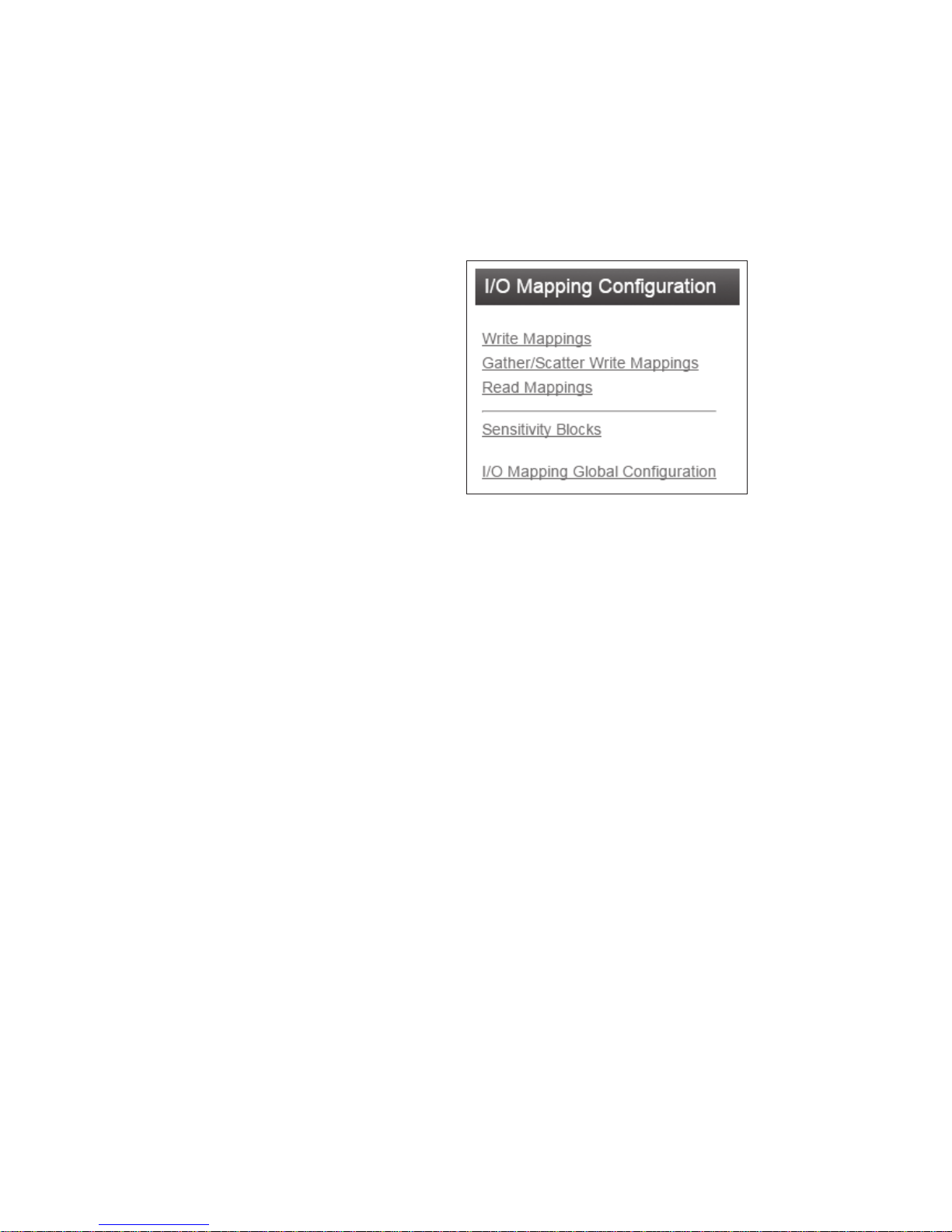
User Manual MN032EN
Effective October 2017
High/Low Alarm For Analog values, the panel changes to the
Invert This allows you to invert the status of a digital
Register/Display
Pt 1/2
Tag Groups: This section allows you to group together related
display panels. Each row of the table describes one tag group. Use
the “Add Entry”, “Insert Entry” and “Delete Entry” buttons to build
your list of tag groups, the configure the following items.
Name The name you want to give to the group of tags.
Count The number of tags to include in the group.
configured “Alarm Color” when the value moves
above or below these limits. For Digital values,
the panel changes to the alarm color if the digital
value is ON and the High Alarm is One(1), or if
the Digital value is OFF, and the High alarm is
Zero (0).
point so that the panel shows “On” when the
digital is zero, and “Off” when the digital is one.
This sets the scaling for the Analog display. Set
the high and low register value in Register Pt
1/2 field, and the desired display value in the
corresponding Display Pt 1/2 fields. The display
will scale linearly between these points.
215U-2 802.11
wireless I/O and gateway
•
Read: for requesting contiguous blocks of data. Normally used
where a single master station is controlling all communications in
a system.
You can set write messages (both Block and gather-scatter) to be
triggered on a time, on a change-of-state, or a combination of both.
You can configure how the write messages change-of-state are
triggered through the sensitivity blocks. You can configure read
messages to be triggered on a time basis or by a command from a
remote master station.
Dashboard Switches: This section allows you to add switches to
the dashboard to control digital output points. When you slide the
switch on the dashboard, the configured digital output changes
state. Each row of the table describes one switch. Use the “Add
Entry”, “Insert Entry” and “Delete Entry” buttons to build your
list of items to display on the dashboard. For each item, enter the
configuration parameters.
Name The name you want to give to the switch.
Register The Digital output register you want the
switch to control.
Invert Check this if you want the register state to be Off
when the switch is On, and On when the switch
is Off.
I/O Mapping configuration
You can configure the 215U-2 to copy the status of I/O registers
to other ELPRO series products using the WIB register mapping
protocol. WIB protocol is supported by many of the ELPRO product
series, including 915U-2, 415U-2, 215U-2, and 115E-2 devices.
The WIB protocol is an event based protocol with integrity reporting.
This allows you to configure a network supporting both low latency
and low bandwidth requirements, while still supporting data
integrity. WIB messages are transferred between ELPRO series
devices using standard IP addressing and UDP/IP message delivery.
WIB Protocol uses UDP protocol on port number 4370.
ote:N Devices can be configured in Routed mode, where the devices have
separate interface addresses for Radio and Ethernet ports. Make sure you
enter the correct address to allow your message to reach the device via
the correct interface. If the device you are mapping to is not on the same
subnetwork, you may need to configure additional routing rules in your
network to allow the message to reach its destination.
The 215U-2 supports three separate types of message. You can
select the message types that best suit your application.
•
Block Write: for transferring contiguous blocks of data, between
two stations.
•
Gather-Scatter Write: for transferring non-contiguous blocks of
data between two stations.
Figure 27. I/O Mapping configuration
Selecting “I/O Mappings” on the right of the screen takes you
to a page where you can reach configuration pages for each
mapping type.
Click on the link to reach the mapping configuration page that you
need to access.
Write Mappings are messages sent from the local unit to write
values into registers of a remote unit.
Block Write Mappings: These mappings work with blocks of
registers. They are the best choice when you want to transfer blocks
of contiguous register data from one device to another.
Gather Scatter Write Mappings: These mappings work by choosing
individual I/O points and allowing each I/O point to be mapped to
an individual I/O point at the remote end. They are more difficult to
configure, but are the best choice when your I/O data that you need
to transfer is not in contiguous blocks.
Click on the “Write Mappings” link to access the block write
mappings configuration table, or on the “Gather Scatter Write
Mappings” link to access the gather scatter configuration table.
ote:N The 215U-2 contains one automatically generated Gather Scatter Write
Mapping. This implements the Back-to-Back I/O Mapping function described in
section “Default Back-To-Back Gather Scatter Mapping” on page 20.
Each line of the table defines one mapping message. Use the “Add
Entry”, “Insert Entry” and “Delete Entry” buttons to build your list of
write mappings to configure. Edit the items as below:
Enabled You can enable or disable individual mappings for
testing and diagnostics. Ensure this is checked for
the mapping to operate.
Name Enter a descriptive name for the mapping.
Destination IP Enter the IP Address of the destination ELPRO
series product.
ote:N When operating in ProMesh mode, there you
can use the special names “BASE” and “REMOTE”
as the destination device. BASE is the IP address of
the system Base device, and REMOTE is the
IP address of the Mesh Node that last sent an
I/O message to the Base.
18
EATON www.eaton.com
Page 23

215U-2 802.11
wireless I/O and gateway
User Manual MN032EN
Effective October 2017
Ack This option requests the remote device to send
an acknowledgement that it has received the
message. You can use this to receive positive
indication that the message was delivered
successfully. If you leave this blank, the message
will be sent on a best effort basis.
Invert You can invert the values in the mapping. This
is most useful for discrete values, but may also
be used for analogs. Inverting an analog value
reverses the scale, so that a 4mA signal will
appear as 20mA and a 20mA will appear as 4mA.
Update
Period (s)
This is the period in seconds between updates
of the messages status when there is no change
in the value to force an update. This provides a
way for the receiving unit to ensure the data is
still valid (See section “FailSafe configuration” on
"Failsafe configuration" on page 24). Set this to
zero to disable updates.
Update
Offset (s)
Configures an offset time in seconds for the
update mapping. Used to stagger the update
transmissions so on start-up and every update
period each mapping is transmitted at its own
scheduled time.
If you want to schedule transmissions to happen
at specific times, use this setting to provide a
different offset for each mapping, and disable the
“Cos Resets Update Timer” setting below so that
the transmissions stay on a fixed schedule.
COS Delay (s) This is the time in seconds that the unit will delay
after detecting a Change of State (COS) before
transmitting the mapping message. You can set
a longer COS delay to allow changing values to
settle before transmitting, and to limit the number
of times the mapping message is transmitted if
the input is continuously varying.
COS Enabled This enables the COS function. If this is checked,
then the inputs will be monitored for a change
since the last transmitted value. When they
change the transmission of the new values is
activated.
ote:N For Digtal inputs, a change is from 1 to 0 or 0
to 1. For analog inputs you can configure the change
required to trigger the COS function. See section
“Sensitivity Blocks” below.
COS Resets
Update Timer
When you select this option, the update timer is
restarted each time a Change of State triggers a
transmission. Leave this unchecked if you want
message transmission to happen on a fixed
schedule.
Force Register You can select another register to force the
write mapping to be transmitted, even if there
is no Change of State, and the update timer
has not expired. When the register is written to
a non-zero value, the transmission is triggered.
Once the message has been sent, this register is
set back to zero.
ote:N Don’t use a Discrete input register (10001-10008)
as a force register. The Discrete input will not turn off,
and the mapping will continue to be forced while the
input is active.
Fail Register You can select a physical digital output or a digital
register to signal if the write mapping was not
successful. If no Acknowledgement was received
for the message, then the fail signal will activate.
If you are using a physical Digital Output (register
1-8), the output will turn On when the mapping
fails to receive the ACK message.
ote:N The “Ack” field must be checked for the fail
indication to operate.
The remaining fields define which I/O points are sent in the
message, and where they are placed in the destination register map.
These settings depend on whether the mapping is a gather-scatter
or block write mapping.
Block Write Mappings specify the a starting register at the local and
remote locations and a count of registers to transfer.
First Local
Register
First Remote
Register
This is the first register in the local unit that is
transmitted to the remote site.
This is the location in the remote device’s register
map where the first of the register block is
placed.
Register Count This is the number of registers in the block.
Gather Scatter Write Mappings specify each source and
destination register individually. You can enter up to 32 sourcedestination register pairs in one gather scatter mapping.
Local 1 – 32 These are the register locations to send from the
local unit. List each register that needs to be sent
in the mapping.
Remote 1 – 32 These are the register locations where the data
will be placed in the remote device. List the
location in the remote module for each of the
local input registers.
Block Read Mappings provide an alternative method of transferring
data. These mappings are used when you have a central site that is
polling remote sites on a regular basis.
Click on the “Read Mappings” link to access the block read
mappings configuration table.
Each line of the table defines one mapping message. Use the “Add
Entry”, “Insert Entry” and “Delete Entry” buttons to build your list of
read mappings to configure. Edit the items as below:
Enabled You can enable or disable individual mappings for
testing and diagnostics. Ensure this is checked for
the mapping to operate.
Name Enter a descriptive name for the mapping.
Destination IP Enter the IP Address of the destination ELPRO
series product where you will read the data from.
Invert You can invert the values in the mapping. This
is most useful for discrete values, but may also
be used for analogs. Inverting an analog value
reverses the scale, so that a 4mA signal will
appear as 20mA and a 20mA will appear as 4mA.
Update
Period(s)
This is the period in seconds between updates of
the messages status.
EATON www.eaton.com
19
Page 24

User Manual MN032EN
Effective October 2017
215U-2 802.11
wireless I/O and gateway
Update
Offset(s)
Configures an offset time in seconds for the
update mapping. Used to stagger the update
transmissions so that each read message can be
timed to happen at it’s own time slot.
Response
Timeout(s)
This is the time in seconds to wait for a response
to the read request. For devices with high speed
radio, a value of 1 second is normally suitable.
Force Register You can select another register to force the read
request to be transmitted, even if the update
timer has not expired. When the register is
written to a non-zero value, the transmission is
triggered. Once the message has been sent, this
register is automatically set back to zero.
ote:N Don’t use a Discrete input register (10001-10008)
as a force register. The Discrete input will not turn off,
and the mapping will continue to be forced while the
input is active.
Fail Register You can select a physical digital output or a digital
register to signal if there was no response to the
read request. If no response was received for the
message within the configured response timeout,
then the fail signal will activate. If you are using
a physical Digital Output (register 1-8), the output
will turn On when the mapping fails to receive
the response message.
Sensitivity Blocks allow you to configure how much an analog
signal needs to change to trigger a Change of State indication to
activate a Write Mapping. You can configure multiple blocks of
Analog signals. Each analog signal within the one block has the
same sensitivity.
Click on the “Sensitivity Blocks” link to access the configuration table.
Each line of the table defines one sensitivity block. Use the “Add
Entry”, “Insert Entry” and “Delete Entry” buttons to build your list of
blocks to configure. Edit the items as below:
First Register The first Analog register in this sensitivity block.
Count The number of Analog registers in this sensitivity
block.
Value The sensitivity value. For 16-bit registers, this is
expressed in counts. For floating point registers
(range 38001 – 38040) this is expressed in the
inputs units (Volts, mA, or Hz depending on the
input type).
I/O Mapping Global Configuration allows you to configure
advanced functions of the I/O mappings. The default values are
usually suitable, and will only need changing for unusual applications.
Tx Attempts for
Acknowledged
Messages
This is the number of times the device will
transmit a Read Mapping, or a Write Mapping
with the Ack Flag set, when it does not receive
a response to the message. If the message
is transmitted this number of times without a
response, then it will indicate as failed.
Tx Count for
Unacknowledged
messages
This is the number of times Write mappings
will be transmitted if they don’t have the
ACK flag set. You can configure to transmit
unacknowledged messages multiple times.
Acknowledge
Timeout
This is how long the device will wait for an
Acknowledgement when it is sending Write
mappings with the ACK flag set.
ote:N The Response timeout for Read mappings is set
in the individual read mapping configuration.
Default Back-To-Back gather scatter mapping
The 215U-2 comes pre-configured with a gather-scatter I/O mapping,
allowing you to send I/O data between the Base site and one
Remote site. This function is available in ProMesh mode, and maps
all of the I/O to appear at the remote site. You can enable this
mapping by checking the “Enable I/O Data” checkbox on the
Quick Start page. You can view and edit this mapping by selecting
“I/O Mappings >> Gather Scatter Mappings” from the Configuration
side menu.
This pre-configured mapping supports connection of 115S-12 and
115S-13 expansion modules to your Base and Remote sites to
increase the number of I/O. When you do this, you must configure
the 115S-12 with address 01 and the 115S-13 with address 02. You
set the address using the rotary switches on the bottom panel of
the 115S module. Refer to section “Adding expansion I/O modules”
on page 22 for instructions on how to connect 115S modules.
ote:N You don’t need to connect the 115S modules. You can use only the
base and remote modules, or just connect one 115S-12 module at one end,
and one 115S-13 at the other end.
Table 10.
Input point (Lo cal) Output point (Remote)
215U-2 215U-2
DI1 – DI4 DO4-DO8
AI1 – AI2 (4-20mA) AO1-AO2
Expansion 115S-12 Expansion 115S-13
DI1 – DI6 DO1 – DO6
AI1 – AI8 AO1 – AO8
Expansion 115S-13 Expansion 115S-12
DI7 – DI8 DO7 – DO8
20
EATON www.eaton.com
Page 25
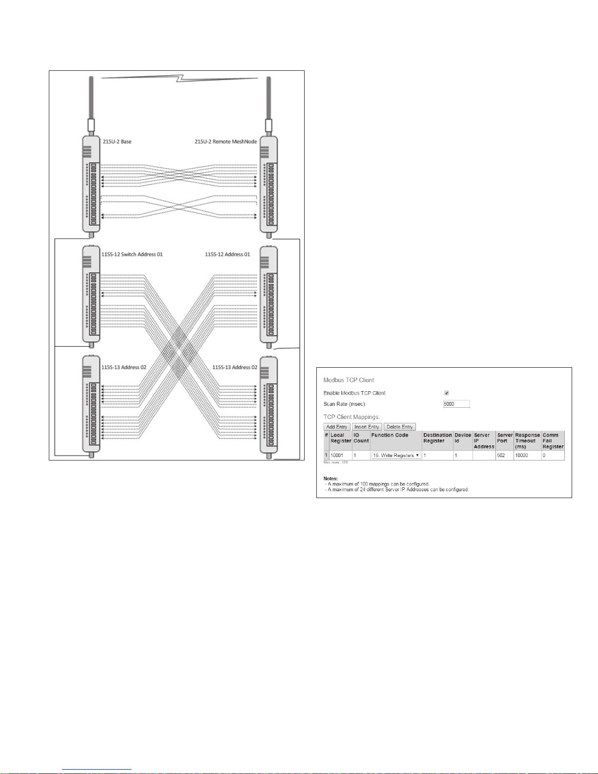
215U-2 802.11
wireless I/O and gateway
User Manual MN032EN
Effective October 2017
Serial Server You can configure the port to act as a serial
Modbus RTU
Master
ote:N Make sure that "Enable Modbus TCP Client" is selected on the Modbus
TCP page.
Data Rate: Set the serial baud rate to match the connected device.
Standard baud rates from 1200 baud to 115,200 baud are supported.
Data Format: Set the serial data format. Select from the drop-down
options in the format <data-bits><parity><stop-bits>. The options
support 7 or 8 data bits, odd (O), even (E), mark (M) or space (S)
parity, and one (1) or two (2) stop bits.
Flow Control: (RS-232 port only) This allows you to enable hardware
flow control on the RS-232 port. Because Modbus is a poll-response
protocol, the flow control will normally be set to “None”. When using
the serial server, you should set this to match the settings of the
device you are connecting to.
Maximum Device ID to poll: (only for Expansion I/O setting). This
is the maximum device ID for connected 115S modules. Set this to
match the actual number of 115S modules connected to speed up
the I/O device polling.
Modbus RTU Master settings: Some additional items are available
when you select this mode.
server. In this mode, you connect to the device
on standard TCP port to access the device’s
serial port from a remote TCP connection.
Configures the port to operate as a Modbus
master device. The commands are configured
in the “Modbus Master Mappings” table that is
enabled when you select this option (see below).
Figure 28. Back to Back mappings
Serial functionality – Connecting to RS-232 and
RS-485 devices
The 215U-2 has an RS-232 and an RS-485 port for serial
communications. You can use these ports to connect to external
devices using serial server functionality or using the in-built Modbus
client or server functionality.
From the right-side menu, select “Configuration >> Serial” to
configure the serial port operation.
You can configure the operation of the RS-232 and RS-485 serial
ports separately. By default, the RS-485 serial port is configured to
support automatic connection to 115S I/O expansion modules. The
available options for each serial port are Port Type. This selects the
operating mode for the port.
None Disables all functionality on the serial port.
Expansion I/O Allows connection to 115S Expansion I/O
Modbus RTU
Slave
modules.
Configures the port to act as a Modbus slave
to a Modbus master device connected to the
serial port.
ote:N Make sure that "Enable Modbus TCP Server" is
selected on the Modbus TCP page.
Figure 29. Modbus RTU Master settings
Scan Rate (msec): This is the time delay in milliseconds between
completing the processing of one Modbus Master Mapping and
beginning the next. This delay begins after receiving a response to a
client mapping message, or if there is no response, at the end of the
timeout for that message.
Response Timeout (msec): This is the time that the Modbus
master will wait for a response from the remote Modbus slave
before deciding that the transaction has failed.
Modbus Master Mappings: Use the “Add Entry”, “Insert Entry”
and “Delete Entry” buttons to build your list of Modbus commands.
For each command, you set the following items.
Local Register This is the register in the local device that will
I/O Count The number of I/O points to transfer. For bit (Coil)
either receive the data from the remote device
(Read command) or be used as data to send to
the remote device (Write command). Refer to
section "Register Memory Map" on page 45 for
detail of the local device register map.
commands, this is the number of 1-bit registers
to transfer. For register (Word) commands, this is
the number of 16-bit registers to transfer.
EATON www.eaton.com
21
Page 26
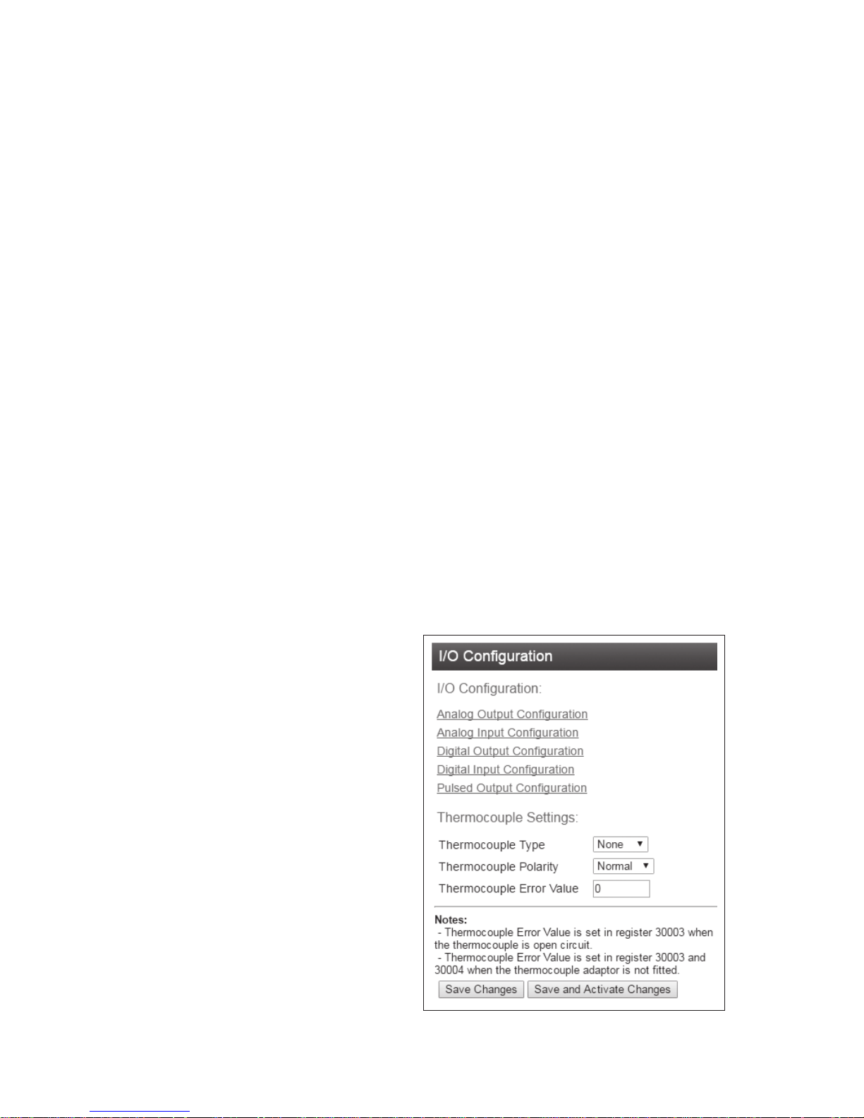
User Manual MN032EN
Effective October 2017
215U-2 802.11
wireless I/O and gateway
Function Code The Modbus function code to use in the
message.
Destination
Register
The register number in the remote device that
will either be used as a destination for the
data transfer (Write) or as a source for the data
(Read).
Device ID The Modbus Device ID (also called Device
Address) for the remote device.
Comm Fail
Register
You can choose a separate register in the local
register map to indicate that the remote device
has failed to respond inside the configured
response timeout. If this register is a bit register,
it will be set ON if the transaction fails, and OFF
if the transaction is successful. If this register is
a word register, it will receive an extended code
indicating the reason for the failure. It will be
set to zero on successful transaction. Refer to
section “Modbus Error Codes” on page 51.
Modbus TCP to RTU Gateway allows an Ethernet Modbus/TCP
Client (Master) to communicate with a serial Modbus RTU Slave.
The 215U-2 performs the protocol conversion and is directly
connected to the Modbus serial device (i.e. only this module needs
to have Modbus TCP to RTU Gateway enabled).
Adding expansion I/O modules
You can connect additional 115S serial expansion I/O modules to
the 215U-2 module if more I/O is required. The RS-485 serial port
on the 215U-2 is configured by default to communicate with 115S
expansion modules using the Modbus protocol. The default serial
parameters of the RS-485 port on the 215U-2 are 9600 baud, no
parity, 8 data bits, 1 stop bit, which match the default settings of the
115S serial expansion modules. You can change these parameters
to increase poll speeds in larger systems, but the serial module’s
parameters must match that of the 215U-2 RS-485 port.
If more than three serial expansion I/O modules are added to the
215U-2 module, you will need to adjust the Maximum Connections
setting for RS-485 or RS-232.
ote:N Reducing the Maximum Connections setting will slightly improve the
serial scan time. However, you need to make sure that the slave addresses
fall within the Maximum Connections. If the Slave address is above the
Maximum Connections, it will not be polled.
When you connect the serial expansion module, before powering
on, set the expansion module address using the rotary switches on
the bottom of the module. Assign addresses sequentially, starting
at address 1. Make a note of the module address. This address will
be used as an offset to locate the I/O within the 215U-2. Also make
sure that the termination switch is “on” (down) for the last module in
the RS-485 loop.
ote:N Failure to terminate the RS-485 correctly will result in modules not
operating correctly.
115S Expansion I/O Memory Map: The I/O data on the 115S
module is read into memory locations according to their Modbus
address. The maximum supported Modbus address is 19. Each 115S
module has an offset that applies to the location of its registers.
This offset is equal to the units' Modbus address (selected on
the rotary switch on the end of the 115S expansion I/O module),
multiplied by 20. If the modules Modbus address is 15, the offset
value will be 15 X 20 = 300.
For example, if connecting a 115S-11 (16 x DIO) with address #15:
•
Digital input 1 will be at register location 10301
•
Digital Output 1 will be at register location 301.
•
If using a 115S-12 (8 x DIO and 8 AIN) with address 16:
• Digital input 1 will be at register location 10321
• Analog input 1 will be at register location 30321 For a detailed
address map of the serial expansion I/O modules, see section
“Expansion I/O Registers” on page 47.
When adding expansion I/O modules to the 215U-2, there are
two inbuilt registers indicating the communication status of the
expansion I/O module:
• Communication Fail — Located at register location 10019 +
offset value. This register indicates “1”when the module is in
failure.
• Communication OK — Located at register location 10020
+offset value. This register indicates “1”when the module is
communicating properly.
Configuration of the on-board I/O
The default I/O configuration on the 215U-2 module is suitable for
most applications. If needed, you can change the configuration
to meet the special needs of your application. You access the I/O
configuration through the right-side menu under “Configuration >>
Onboard I/O”.
From Here, configure the thermocouple input directly, or select the
type of I/O you want to configure.
22
EATON www.eaton.com
Figure 30. I/O Configuration
Page 27
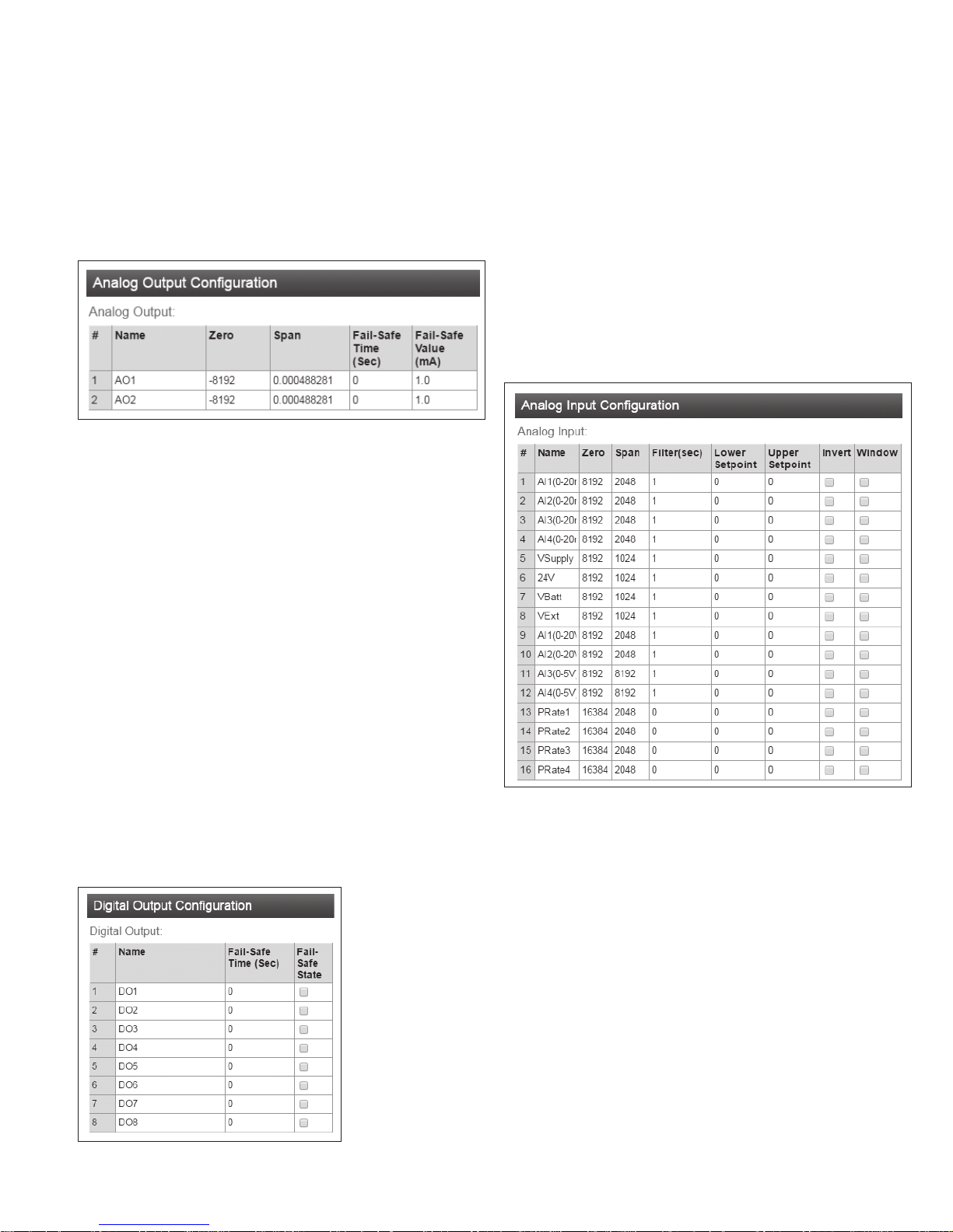
215U-2 802.11
wireless I/O and gateway
User Manual MN032EN
Effective October 2017
Configuring For use with the TC-ADP thermocouple module:
You can purchase the Thermocopule module (TC-ADP) separately.
This replaces analog inputs 3 and 4. Look at the documentation with
the TC-ADP module for a detailed description on configuring. If you
are not using the thermocouple module, ensure Thermocouple Type
is set to “None”.
Configuring the Analog Outputs: You can configure the analog
outputs to change the way the outputs are scaled, and to set up a
local fail-safe in the case that communications is lost.
Figure 31. Analog output configuration
Name You can give the I/O point a descriptive name if
Zero and Span These values set the scaling of the analog
Fail-Safe Time
(Sec)
Fail-Safe Value
(mA)
you like.
outputs. The scaling values are applied to the
raw register value, to give the output value in
milli-amps. The raw value is a 16-bit unsigned
value. The zero value has units of raw-counts.
The Span value has units of milli-amps per
raw-count.
Output(mA) = Span × (Raw + Zero)
The output needs to receive an message
updating its status before this time expires.
Normally this is set to at least twice the
update time for the message that sets the
output status.
If there is no update message received within
the configured Fail-Safe time, then the output is
set to this value to indicate the communications
failure. This value should be outside the normal
range of values for the data that is setting the
output.
Name You can give the I/O point a descriptive name if
Fail-Safe Time
(Sec)
Fail-Safe State If there is no update message received within
Configuring the Analog Inputs: You can configure the behavior of
the analog inputs to change the way the inputs are scaled, and to
configure the behavior of the digital set-points that are associated
with the analog inputs.
Figure 33. Analog input configuration
you like.
The output needs to receive a message updating
its status before this time expires. Normally this
is set to at least twice the update time for the
message that sets the output status.
the configured Fail-Safe time, then the output is
set to this value to indicate the communications
failure. Check this box to have the output fail
“On”. Clear to have the output fail to “Off”.
Configuring the Digital Outputs: You can configure the digital
outputs to set up a local fail-safe in the case that communications
is lost.
Figure 32. Digital output configuration
Name You can give the I/O point a descriptive name if
Zero and Span These values set the scaling of the analog
For current input (measured value is in mA)
For voltage input (measured value is in V)
For pulse rate
input
you like.
inputs. The scaling values are applied to the
measured value (either volts, milli-amps, or
hertz), to give the 16-bit raw register value. The
zero value has units of raw-counts. The Span
value has units of raw-counts per measured unit.
Raw = Zero + Span × Measured(mA)
Raw = Zero + Span × Measured(V)
(measured value is in Hz)
Raw = Zero + Span × Measured(Hz)
EATON www.eaton.com
23
Page 28
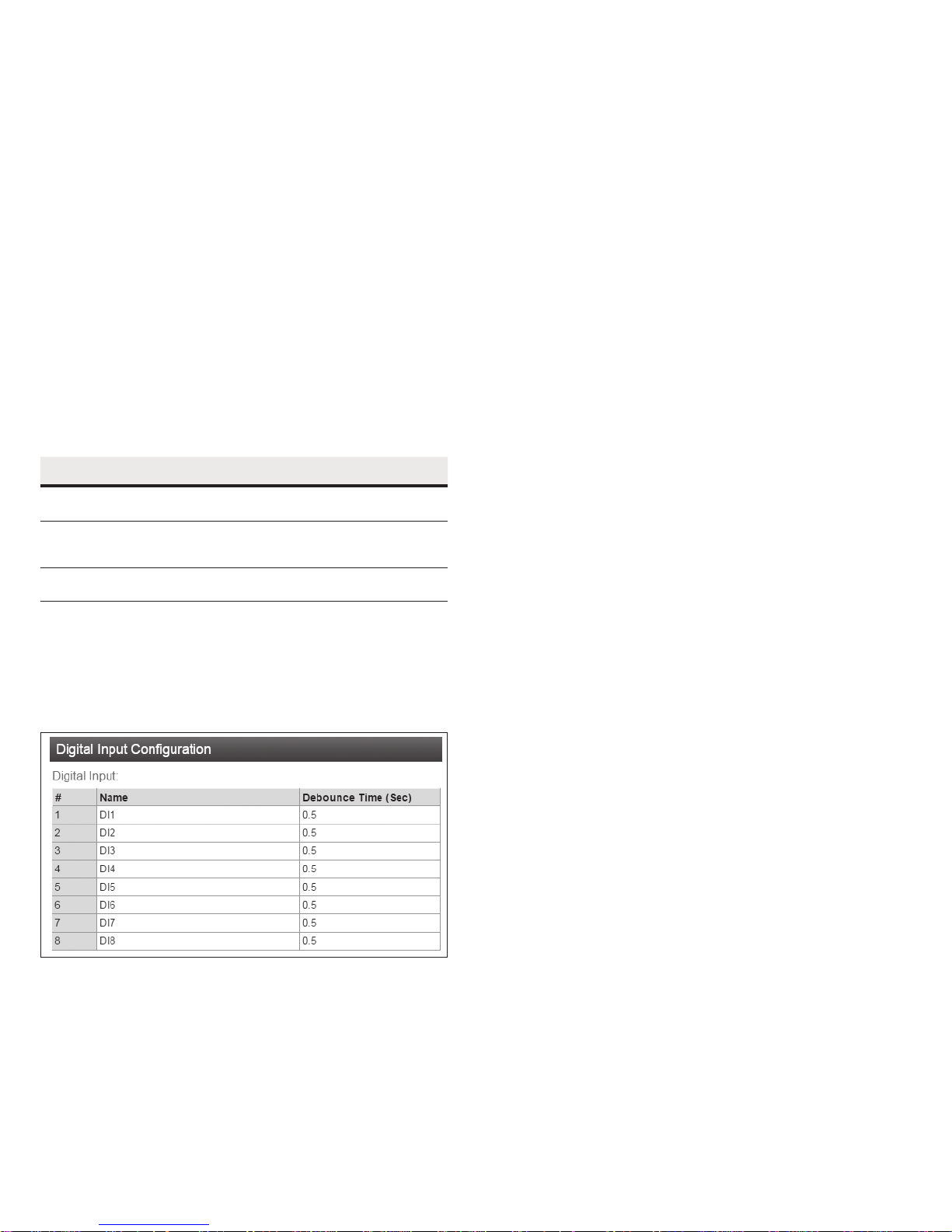
User Manual MN032EN
Effective October 2017
215U-2 802.11
wireless I/O and gateway
Filter (sec) Analog inputs for voltage and current
measurement can be filtered to remove the
effects of noise on the input. The filter time is
the time for the measured value to shift by 0.632
-1
) of the changed value.
Set Point
Configuration
(1-e
Measured(t) = input × {1−e
Each analog input is associated with a digital
input point that acts as a set point to show the
−t
/filter
}
status of the analog input. Refer to Table 1 for
detail of how the setpoints operate
Lower/Upper Setpoint: Configure the set
points with the desired low and high measured
values (mA, V, or Hz).
Invert: Check this to invert the state of the
digital set-point. Clear this to set direct mode.
Window: Check this to set windowed mode for
the set point. Clear this to have the set-point
operate in hysteresis mode.
Table 11. Setpoint operation
Level/Mode
Above Upper
Setpoint
Between
Upper and
Lower
Below Lower
Setpoint
Invert
Window
ON Off ON Off
Off ON No change No change
ON Off Off ON
Direct
Window
Invert
Hysteresis
Direct
Hysteresis
Configuring the Digital Inputs: You can configure the behavior of
the digital inputs to control Debounce operation on these inputs. Set
the debounce time to the desired delay. The physical digital input
must remain changed for the configured amount of time before a
change is registered and the internal register is updated with the
new value. This allows the device to ignore inputs that are a result of
noise or bouncing contacts.
Figure 34. Digital input configuration
Save Changes: Clicking this button saves changes to non-volatile
storage. Changes don’t take effect until the device has been
restarted. If you plan to make changes to multiple pages, use this
button before navigating to another page.
Save Change and Reset: Clicking this button immediately applies
the changes on you have made by saving the new configuration to
non-volatile storage, then forcing the device to reset immediately.
Once the device has booted, the new changes will be in effect.
Failsafe configuration
You use the failsafe configuration to set up initial values for registers
and to configure how the register should behave if it doesn’t get
refreshed within a safety window of time. Failsafe configuration
also allows you to configure the device to reboot if it reaches an
unexpected state.
ote:N You normally don’t use the failsafe configuration for physical Inputs or
outputs. For physical outputs, you can configure the failsafe behavior in the
I/O Configuration screens.
Fail Safe Blocks: You use this configuration to set up the behavior
of blocks of registers that you want to intialise to a certain status,
or if you want to have them go to a safe value in the case that
communication is lost.
The default behavior for registers without a fail-safe configuration
is to intialise the register to Zero (or Off) and to have no fail-safe
timeout configured.
Fail-Safe configuration can set a register to an “Invalid” state.
In this state, the register will appear to be not present. Modbus
polls covering this address will return an “Invalid Address” error, and
Modbus master mappings sending this address will not activate.
The Invalid state is cleared once a value is written to the register.
Add/Insert/
Delete Entry
Use these buttons to set up your table with one
entry for each block of I/O that you want to set
up. The setup will be the same for each item in
one block.
First Register This is the address of the first register in the block.
Count This is the number of registers in the block (the
registers are always in a contiguous block).
Timeout (s) The fail-safe time out to use for this block.
Set the timeout to Zero to disable the fail-safe
timeout.
Initialize at Start Check this if you want to initialize the register at
startup. Normally this will be checked to initialize
the register.
ote:N If you clear this checkbox, then at startup the
register state will be “Invalid”. In this state, the register
will have no valid value until it has its value written
through Modbus or WIB message protocol, or through
the I/O Diagnostics page.
Startup Value If you checked “Initialize at start”, then the
register will be initialized with this value when
the unit is started.
Invalidate on Fail Check this box if you want to set the register
state to “Invalid” when the fail-safe timer
expires. If you want to set the register to a
particular value, then uncheck this box and enter
a value for “Fail Value”.
Fail Value This is the value that you want the register
to have if the fail-safe timer expires. This will
normally be a special value that indicates a
failure state to your process.
Fail Safe Reboot: You can use this configuration to re-start the
module if it loses communication for a long time, which could the
the result of a module software error that may be recovered by a
reboot. To use this feature, you need to set up a register to indicate
that the system is operating correctly. If this register stays cleared
(Zero or Off) for the configured time, then the module will restart.
Reboot Register The register to use to indicate the system is healthy.
Reboot Timeout
(sec)
The number of seconds to wait for the system
health indication to return before restarting the
module.
24
EATON www.eaton.com
Page 29
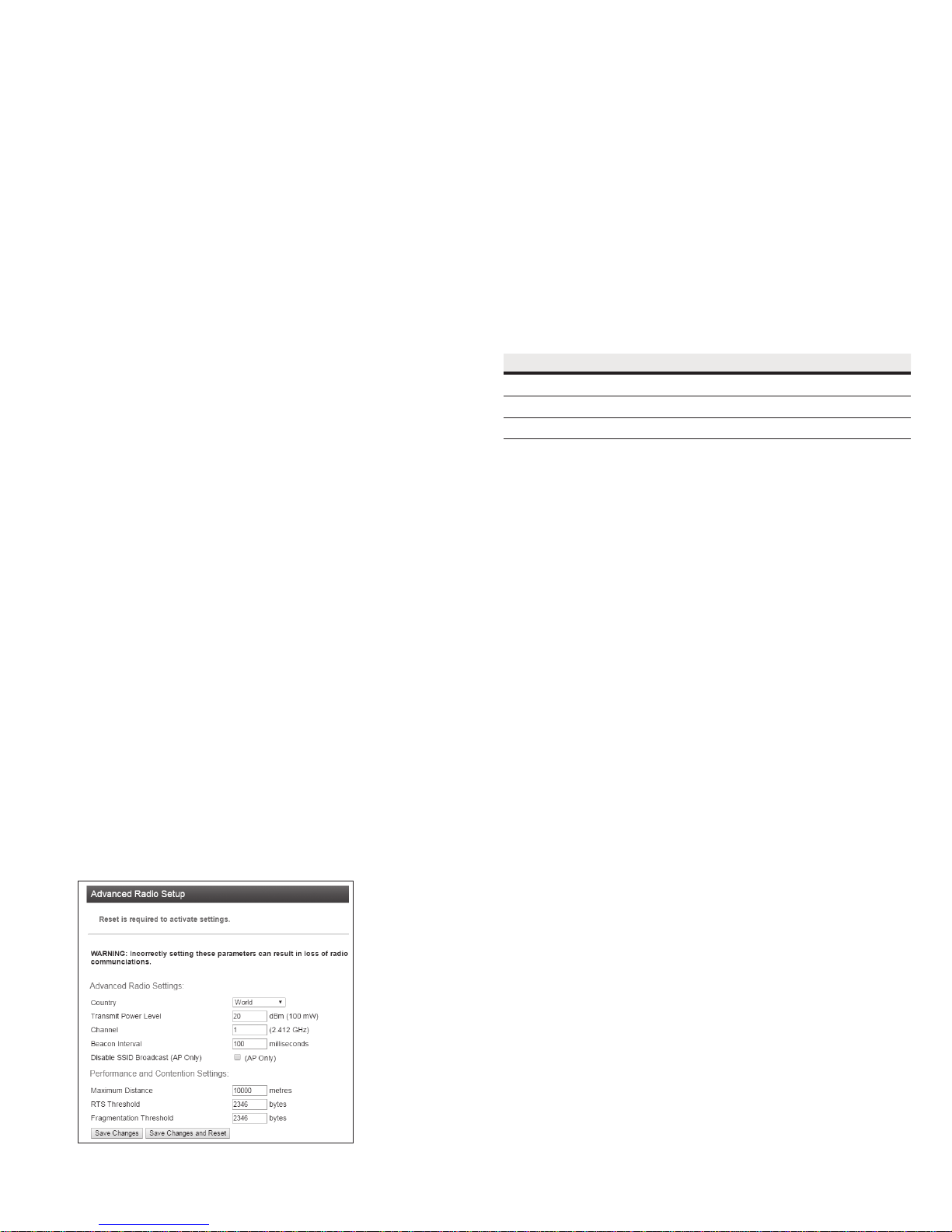
215U-2 802.11
wireless I/O and gateway
Advanced network conguration
This section describes the Advanced features of the 215U-2
available for setting up complex networks. This allows you to make
changes away from the default networking setup. You might need
to make changes in this section if you need to support an unusual
application, or if you need to interoperate with equipment from other
manufacturers. If you’re setting up a network of 215U-2 devices, you
normally won’t need to change any of the settings in this section.
To access these options, select “Full Configuration” on the right
side menu to show the full configuration menu, and select from the
items under the “Advanced Networking” section.
Network
This configuration repeats much of the configuration available on
the Quick Start page. Settings that appear on both pages you can
set on either page. Additional items that are only on the Network
Configuration page are listed here.
Network Mode: This allows you to choose between bridged and
routed networking. Bridged networking is the simplest to configure
and will be the correct choice in almost all networks.
User Manual MN032EN
Effective October 2017
Country: The module is configured from the factory to allow
operation globally. To take advantage of additional radio channels and
higher allowed power in some countries, you can select a different
location.
Transmit Power Level: You can select a lower power level than
the default. If you are using a high gain antenna, you may need to
lower the transmit power to keep the EIRP inside the limit for your
country.
Channel: You can select a radio channel to avoid interference from
other 802.11 networks in your area, or to allocate radio spectrum
between several of your own networks. For 802.11 communication,
channels 1,6, and 11 are non-overlapping.
Table 12. Transmitter power and channels
Region Allowed channels Power setting Maximum EIRP
United States 1-11 23 dBm (200mW ) +36 dBm
Europe 1-13 20 dBm (100mW) +20 dBm
Australia 1-13 23 dBm(200mW) +36 dBm
Bridge The 215U-2 acts as a network bridge between
the radio and Ethernet ports. Ethernet packets
are transparently passed between the radio and
Ethernet ports using rules learned from traffic
that has already passed.
Router The 215U-2 acts as an IP Router between the
radio and Ethernet ports. Only IP packets are
passed between the radio and Ethernet, which are
on separate sub-networks. You configure the rules
for which packets are transferred on the routing
configuration page.
IP Address/Subnet Mask: When the network mode is set to Bridge,
the Ethernet and Wireless interfaces are bridged together, and the
device has a single IP Address accessible from either interface.
Ethernet IP Address/Netmask: When the network mode is set
to Router, the Ethernet and Wireless interfaces on the device
each have separate IP addresses. This sets the IP address for the
Ethernet interface.
Wireless IP Address/Netmask: When the network mode is set to
Router, the Ethernet and Wireless interfaces on the device each
have separate IP addresses. This sets the IP address for the
wireless interface.
Radio
These settings allow you to fine tune the operation of the radio.
Beacon Interval: This setting applies to Access Point (Manual mode),
Base (ProMesh and Fixed Link modes), Mesh Node (ProMesh)
and Repeater (Fixed Link) stations. These stations regularly send
a special beacon message to identify themselves and allow other
devices to connect to them.
You can change the interval between beacons with this setting. You
may need to increase this interval if you have a very large number of
devices in close proximity which are all sending beacons.
ote:N ProMesh Mesh Node stations only send beacons when they are
acting as a repeater for another station, and when they are configured for
Hot Spot operation (See the description for "Enable Hotspot" in "Quickstart
Configuration" on page 14).
Disable SSID Broadcast: This setting applies to Access Point
(Manual mode) devices only. By selecting this option, the device
will not show in another device’s list of available connections. Only
devices that know the configured ESSID parameter will be able to
connect to the Access Point.
Maximum Distance: This setting controls how long the expected
time of flight is for the message to reach a remote location and for
the Acknowledgement to return. The default setting allows for radio
transmission up to 10km (6mi). For a longer radio path (single hop),
increase this value accordingly.
RTS Threshold: This value sets the messages size where RTS
contention control is activated. RTS contention control sends a short
message to reserve the radio channel before sending the longer
message. If you have a system with large messages and where
remote stations cannot receive each other’s messages, then setting
this to a value of 100 may help reduce contention.
Fragmentation Threshold: This setting causes large frames to be
broken into multiple shorter frames. Setting to a smaller value slows
data throughput, but increases the likelihood that a message will be
delivered successfully in situations with high level of interference. By
making the data frames shorter, there is less chance of a clash with
a radio transmission from an interfering device.
Save Changes: Clicking this button saves changes to non-volatile
storage. Changes don’t take effect until the device has been
restarted. If you plan to make changes to multiple pages, use this
button before navigating to another page.
Save Change and Reset: Clicking this button immediately applies
the changes on you have made by saving the new configuration to
non-volatile storage, then forcing the device to reset immediately.
Once the device has booted, the new changes will be in effect.
Figure 35. Advanced radio setup
EATON www.eaton.com
25
Page 30
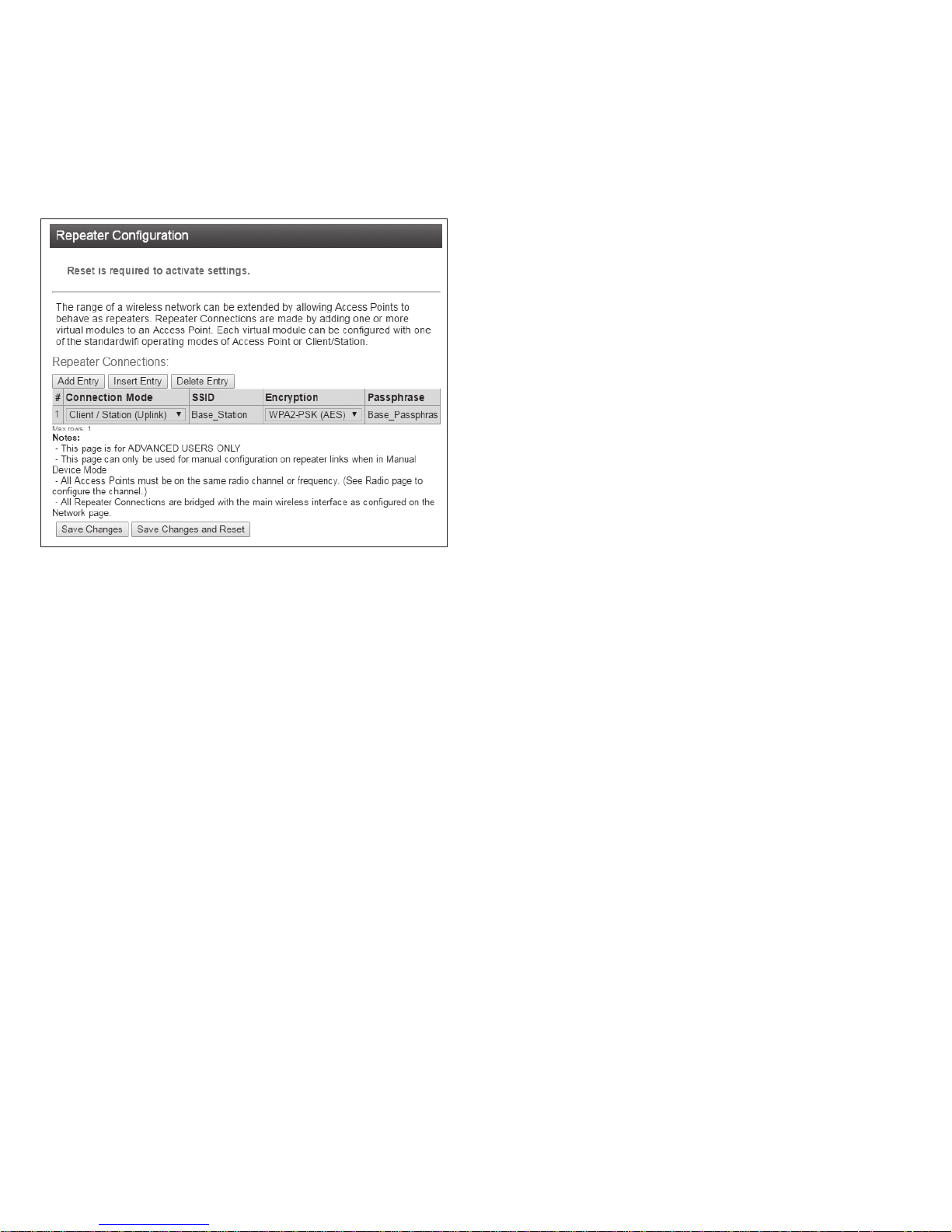
User Manual MN032EN
Effective October 2017
215U-2 802.11
wireless I/O and gateway
Repeaters
Repeaters setting allows you to configure arbitrary radio networks
between different devices. Repeaters configuration is only
available to devices configured as Access Point (Manual mode).
The Repeaters configuration is managed automatically in ProMesh
mode and in Fixed Link mode.
Figure 36. Repeater configuration
The 215U-2 networking architecture allows a single Virtual Client
device to be configured to provide an uplink to another station.
This allows you to set the 215U-2 to be an Access Point on the
main Quick Start page, and also to act as a client to another central
Access Point (e.g. a fixed Infrastructure node). Remotes that connect
to the 215U-2 Access Point can get messages through to the central
AP using the 215U-2 as a repeater.
Use the “Add Entry”, button to add a row to the repeaters table.
Once this is complete, select the following:
Connection
Mode
For the 215U-2, the only allowed connection
mode is “Client/Station (Uplink)”. This creates a
virtual client which you can use to connect to
another central Access Point.
SSID This is the ESSID of the Access Point you want to
connect to.
Encryption This is set to match the encryption used in the
Access Point you want to connect to.
Passphrase This is set to match the encryption passphrase in
the Access Point you want to connect to.
ote:N The 215U-2 only allows one entry in the Repeaters table.
IP Routing
If your system is divided into multiple IP Subnetworks, then you may
need to configure IP Routing rules to allow IP data from the 215U-2
to reach its destination IP address.
If your Base station or Access Point is configured for Routed
Network mode, you will need to add routing rules or to set the
Gateway IP to allow messages from your 215U-2 to get out from the
radio network onto the Ethernet network.
Use the “Add Entry”, “Insert Entry” and “Delete Entry” buttons to
manipulate the rows in the routing rules table so that you have one
row for each routing rule.
The order of routing rules in the table is not important. They
are always applied in order from most specific to least specific.
Nevertheless, to help with understanding the routing rules, you
should order the table in this way.
Once your table entry is complete, set the following:
Name Create a descriptive name for the rule to remind
you of the purpose of this rule at a later date.
Destination This is the destination network IP address.
Combined with the Netmask in the following
field, this determines which destination IP
addresses the rule applies to.
Netmask This is the IP Network mask for the destination
network IP address.
Gateway This is the IP address of the gateway device that
is used to reach the destination IP network. All
packets that are destined for an IP address on
the Destination network will be forwarded to this
Gateway address for delivery to the destination
network.
Enabled You can enable or disable routing rules. Check
this box to activate the rule.
Network Filtering
This configuration screen allows you to set up rules that stop
unwanted traffic from entering your network. The filter applies to
traffic coming from the Ethernet port which would otherwise be
automatically sent over the radio network. This can be useful to
reduce radio message traffic when a device is connected to a busy
Ethernet network where the majority of traffic is not destined for the
radio network.
ote:N It is possible to configure filtering that stops your PC from accessing
the device’s web pages. If you are unable to access the device from the
Ethernet port after configuring Filtering rules, you can either: Access the
device from the USB connection; or restore the device’s default network
settings. For instructions, see “Restoring the factory default connection
settings” on page 42.
Easy IP Filtering allows you to quickly configure filtering for a
network that will only use IP protocols. If your network only uses IP
protocols and IP Addresses in a single range, then use this method
to configure your filtering.
Only allow IPv4 and ARP: Select this option if all of the devices
on your network use IP protocol communications (TCP/IP or UDP
protocols). This will automatically block all non-IP protocols from
reaching the radio network.
Enable Easy IP Filtering: Select this option if all your devices’ IP
addresses are within a single range of addresses. By setting the first
and last IP addresses, only IP messages within this range will be
able to reach the radio network.
First Radio/
Device IP
Last Radio/
Device IP
ote:N Easy IP Filtering is a simple method to set up IP Filter rules. The IP
Filter Rules table is disabled if you select Easy IP Filtering.
Select the lowest IP address of the devices on
the radio network.
Select the highest IP address of the devices on
the network.
26
EATON www.eaton.com
Page 31

215U-2 802.11
wireless I/O and gateway
User Manual MN032EN
Effective October 2017
For more complex networks, where Easy IP Filtering does not
provide the necessary functionality, you may need to set up multiple
filtering rules to fully manage the network traffic.
IP Whitelist or Blacklist: Set this to “Whitelist” if you want to allow
messages that meet the IP Filter Rules. Set this to “Blacklist” if you
want to exclude messages that meet the IP Filtering Rules.
ote:N If you set this to Blacklist, and you haven’t selected “Only allow IPv4
and ARP” above, then the filter will block the specified messages, but any
non-IP protocol messages will pass through the filter.
IP Filter Rules: These rules apply by checking the source address
and destination IP addresses and ports of the message. A rule will
match a message if the IP address is within the defined range, and
the Port number is within the defined range.
Use the “Add Entry”, “Insert Entry” and “Delete Entry” buttons to
manipulate the rows in the table. For each row in the table, enter
the parameters:
Enable Check this to enable the rule. To temporarily
disable a rule you can clear this checkbox.
IP Address
Min/Max
These are the first and last IP addresses that this
rule applies to.
Port Min/Max: This is the range of IP Port numbers (TCP or
UDP Ports) that the rule applies to.
Protocol You can set this to allow only one protocol type
(TCP, UDP or ICMP) or all three protocol types.
ote:N When you select any of these protocols, ARP messages for the
corresponding IP address range are also allowed by default. Also, the Port
range values do not apply and are ignored for ICMP type messages.
MAC Filter Rules: These rules apply by checking the source MAC
of the message. A rule will match a message if the source MAC
matches the configured value.
ote:N Messages that match any of the MAC filter rules are immediately
passed (whitelist) or dropped (blacklist), and are not checked by the IP Filter
Rules. Messages that do not match any filter rules in the whitelist are also
immediately dropped. Messages that do not match any rules in a blacklist are
passed and subsequently checked by the IP Filter Rules.
Use the “Add Entry”, “Insert Entry” and “Delete Entry” buttons to
manipulate the rows in the table. For each row in the table, enter
the parameters:
Enable Check this to enable the rule. To temporarily
disable a rule you can clear this checkbox.
MAC Address This is the MAC address that this rule applies to.
Save Changes: Clicking this button saves changes to non-volatile
storage. Changes don’t take effect until the device has been
restarted. If you plan to make changes to multiple pages, use this
button before navigating to another page.
Save Change and Reset: Clicking this button immediately applies
the changes on you have made by saving the new configuration to
non-volatile storage, then forcing the device to reset immediately.
Once the device has booted, the new changes will be in effect.
DHCP Server
You can configure one device in your network to act as a DHCP
server for other devices in the network. This lets you automatically
assign IP addresses to devices that join the network. This is most
useful when you want to access the network with a device such as
tablet or PC to connect to the devices in the network at their fixed
network addresses.
ote:N You must ensure there is only one DHCP server on your local bridged
network. When your Base site is configured as a Bridge (Default), this
includes DHCP servers connected to the Ethernet network that is connected
to your Base station. When your Base site is configured as a Router, the
DHCP server will only operate on the radio network.
Enable Check this box to enable the DHCP server
functionality
IP Range
Minimum/
Maximum
This sets the range of IP Addresses that are
assigned to devices that connect to the network.
Make sure that this address range does not
overlap any existing fixed address assignments
you have made on your network. Normally
this range will be part of the same IP network
address range as the other devices on your
network.
Gateway IP
Address
If the connected devices need a default gateway,
you can enter this IP address here. Otherwise,
leave this blank.
Primary/
Secondary DNS
Server
If the connected devices will be using DNS
(Domain Name Service) to register or lookup
device names, enter the IP addresses of the
primary (and secondary) DNS Servers here.
Otherwise, leave these blank.
Lease Time: This is the amount of time that connected
devices are allocated an IP address. Once the
lease time expires, the IP address becomes
available for allocation to other DHCP client
devices. The lease time in conjunction with the
IP range limits the number of devices that can
be assigned DHCP addresses within a particular
period. If all of the available IP addresses are
allocated to devices then new devices won’t
be able to join the network until some of the
existing leases expire.
Save Changes: Clicking this button saves changes to non-volatile
storage. Changes don’t take effect until the device has been
restarted. If you plan to make changes to multiple pages, use this
button before navigating to another page.
Save Change and Reset: Clicking this button immediately applies
the changes on you have made by saving the new configuration to
non-volatile storage, then forcing the device to reset immediately.
Once the device has booted, the new changes will be in effect.
VLAN Configuration
VLAN (Virtual Local Area Network) provides a method of segregating
a single bridged network into multiple virtual networks that are
logically separated. This allows segregation and prioritization of traffic
in your network.
ote:N VLAN is an advanced networking technique. You should only need to
configure VLAN functionality if you have to interoperate with a network that
already uses VLAN.
The following configuration items are available for VLAN.
VLAN Mode To disable VLAN functionality, select mode
“VLAN Passthrough”. To enable the VLAN, select
mode “VLAN Aware”.
ote:N When you select mode “VLAN Aware”, the IP
Address and Subnet Mask settings on the main Quick
Start page are ignored. The settings for Management
IP/Netmask on this page are used instead.
ote:N It is possible to configure a VLAN setup that stops your PC from
accessing the device’s web pages. If you are unable to access the device
from the Ethernet port after configuring VLAN rules, you can either: Access
the device from the USB connection; or restore the device’s default network
settings. For instructions, see “Restoring the factory default connection
settings” on P19.
EATON www.eaton.com
27
Page 32
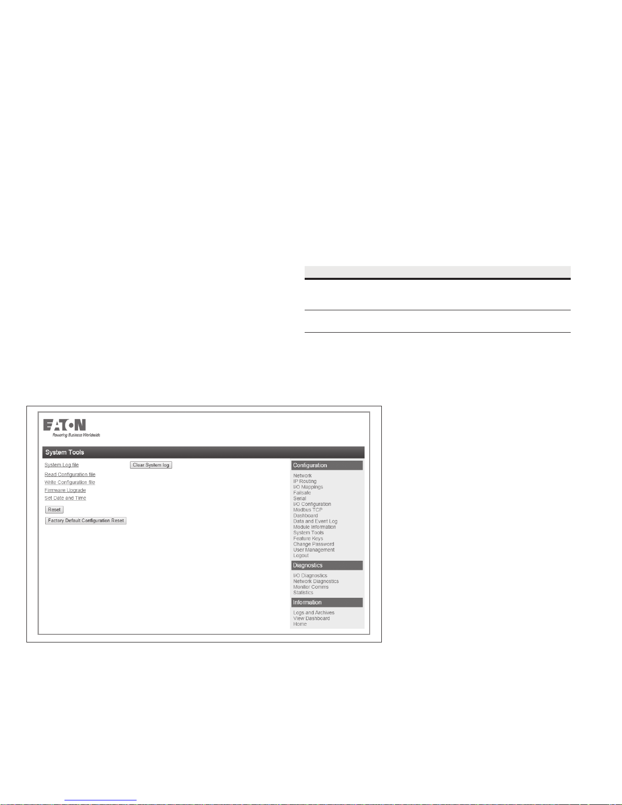
User Manual MN032EN
Effective October 2017
215U-2 802.11
wireless I/O and gateway
Add VLAN Group Click this button to add another VLAN Group.
You can add multiple VLAN groups, with each
group corresponding to a separate VLAN
network. The first VLAN that you add is the
Management VLAN, which provides access to
the device Configuration on the new VLAN using
the same IP Address as configured on the Quick
Start page.
Name You can add a descriptive name for each VLAN
group. By default the first VLAN is named
“Management VLAN”.
VLAN ID This is the 16-bit number that uniquely identifies
the VLAN. Each configured VLAN Group should
have a separate VLAN ID.
VLAN Priority This is the QoS priority given to messages on
this VLAN when sending over the radio channel.
The radio channel takes this setting into account
when prioritizing access to the radio for multiple
separate VLANs.
Bridge STP/
Priority
These settings enable Spanning Tree Protocol
on this VLAN. Spanning Tree Protocol is required
where there are bridging loops which would
otherwise allow packets to circulate continuously
on the network.
System tools
Click System Tools on the menu to perform administrative tasks,
such as clearing the system log, reading or writing the module
configuration, or performing firmware upgrades.
Interface Membership for VLAN: This allows you to set which
interfaces are part of the VLAN. The 215U-2 has two interfaces
which can join the VLAN; The Ethernet Interface and the
Wireless Interface.
ote:N The USB interface is reserved for local access to the device and cannot
be connected to a VLAN.
Interface Select the desired interface(s) to be connected
to the VLAN. Use the “Add Entry” button to add
an additional interface. (You need to select at
least one interface for the VLAN to be reachable
at the device)
Type This specifies how data packets will be treated
when they are received on this interface
(Ingress) or are transmitted on the interface
(Egress).
Table 13.
Type Ingress behavior Egress behavior
Tagged Packet is only accepted if it’s
VLAN ID matches the configured
ID for this VLAN.
Untagged All non-V LAN packets are
received into the VLAN.
Packet is transmit ted as a VLAN
packet with the configured
VLAN ID
Packet is transmit ted as a nonVLAN packet.
Figure 37. System tools
28
EATON www.eaton.com
Page 33
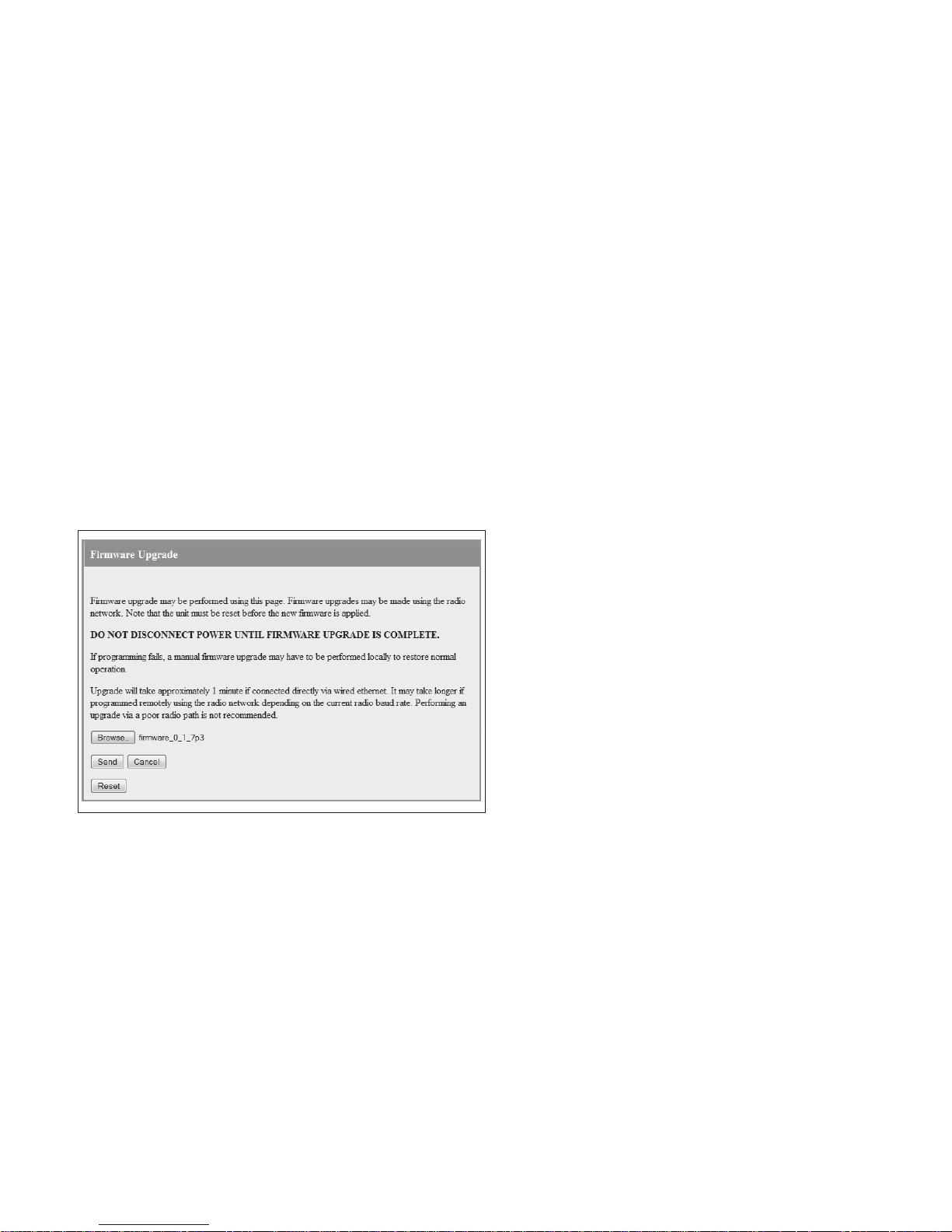
215U-2 802.11
wireless I/O and gateway
User Manual MN032EN
Effective October 2017
System Log File Logs system instructions and other information to the screen. The log screen can then be saved to a file that
may be used by ELPRO technical support to diagnose problems.
Clear System Log Clears the log screen.
Read Configuration File Reads the module configuration to an XML file. To save this file, select “Save As” from the File menu on
your browser.
Write Configuration File Loads a previously saved XML configuration file into the module.
Firmware Upgrade Upgrades the module firmware. For details, see “Patch file firmware upgrade” below.
Set Date and Time Allows you to set the date and time for the device. This feature is associated with the logging function.
Reset Resets the module.
Factory Default
Resets the module and restores its factory default configuration.
Configuration Reset
Patch file firmware upgrade
To upgrade the module firmware locally using a firmware patch file,
click System Tools on the menu, and then click Firmware Upgrade
and browse for the saved firmware patch file. When you locate the
file, click Send to upload the file to the module. A status message
appears. If the upgrade was successful, click Reset. If it was not
successful, repeat the process. (The module must verify that the file
is valid before you can initiate a reset.)
ote:N All existing configuration parameters will be saved. However, if any
new parameters are added to the firmware, the default values will be used.
Setting the date and time
This feature is associated with data logging. The module needs
access to the current date and time to make effective use of data
logging if this feature is enabled on the module (see “Data logging”
on page 38).
To configure the date and time, click System Tools on the menu,
and then click Set Date and Time. This displays the page in
Figure 39. There are two ways you can set the date and time
on this page:
•
Manually enter the date and time.
•
Enable Network Time Protocol (NTP) to retrieve the time and date
from a remote time server. This method requires network access
to an NTP server.
Figure 38. Firmware upgrade
If you set the date and time manually, keep in mind that the date
and time function does not support time zones or daylight savings
time. Normally you should set the time to UTC (Universal Time). You
can set the time to your local time, but you will need to remember
to change the time if your location uses daylight savings. When the
time is set manually, the module uses an internal real-time-clock to
keep time during loss of power. This real time clock has power to
run for at least twelve hours (typical 3-5 days). If the duration of the
power loss is too long, the time at power restoration will be the time
that power was lost.
To use the NTP feature, you need network access to an NTP server.
You can use a public server, or set up your own server. Most modern
operating systems (such as Microsoft
®
Windows and Linux) can be
configured to operate as an NTP server. If the NTP server is on a
different sub-network, you may need to configure routing rules to
allow the device to reach the NTP server. Use the “Ping” command
on the Network Diagnostics page to check if you have connectivity
to the NTP Server IP address.
EATON www.eaton.com
29
Page 34
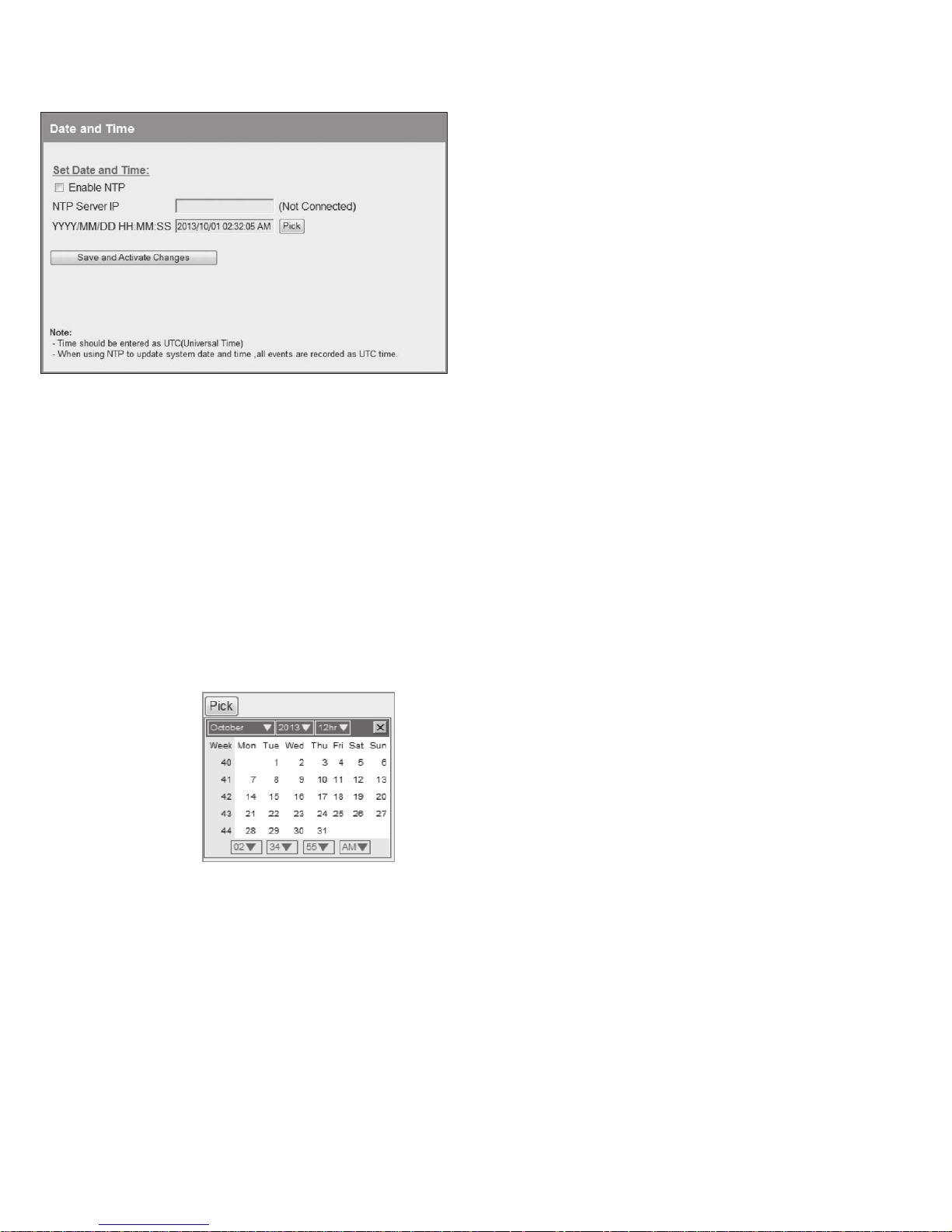
User Manual MN032EN
Effective October 2017
Figure 39. Date and time
215U-2 802.11
wireless I/O and gateway
Enable NTP Select this checkbox to automatically set
NTP Server IP Enter the IP address of the NTP server if
YYY/MM/DD HH:MM:SS Use this field to set the time manually if
Save Changes
and Activate
the time and date in the device from an
external NTP server. You will also need to
enter the IP address of the NTP server in
the NTP Server IP field.
you selected the checkbox to Enable NTP.
there is no access to an NTP server. Click
Pick to display a date and time selection
pop-up. Select the day, month, year
and hour, minute and second, and click
Pick again to set the time and close the
pop-up. To set the time more precisely,
try selecting a time a little in the future
and waiting until that time to click Pick.
After configuring settings, click Save
Changes and Activate.
For manual time, clicking this button sets
the clock with the new time.
For NTP time, after a short delay the
message next to the NTP Server IP
field updates to show whether the
module successfully connected to the
NTP server. If the message is “Not
Connected,” check that the NTP server
is configured correctly, and use the Ping
command on the Network Diagnostics
page to check that the module can reach
the NTP server. After connecting to the
NTP server, the displayed time changes
to match the NTP server. This is normally
UTC time.
30
EATON www.eaton.com
Page 35
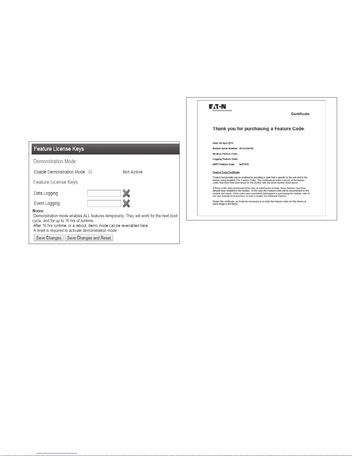
215U-2 802.11
wireless I/O and gateway
User Manual MN032EN
Effective October 2017
Feature license keys
Feature license keys allow you to upgrade the 215U-2 module with
enhanced features or to a more advanced model (for example, by
enabling the data logging option). You can purchase the feature
license keys by contacting your sales representative or local
distributor. To complete the purchase, you will need to provide
the module serial number so that the feature license key can be
generated for the module. The module serial number can be found
on the home page (see Figure 40).
After receiving the feature key certificate, follow the instructions in
“Enabling a feature license key” on this page to install the feature
on the module. You can also temporarily enable all feature license
options by placing the module in demonstration mode. See the
following section, "Using demonstration mode"
Click Feature Keys in the menu to enable or demo feature license
key options (Figure 40).
Enabling a feature license key
Use the following procedure to enable a purchased feature
license key.
To enable a feature license key
1. Make sure that the module serial number on the feature key
certificate (Figure 41) matches the serial number on the label on
the left side of the module.
Figure 40. Feature keys
Demonstration Mode Allows you to temporarily enable all
feature license options. See the following
section, “Using Demonstration Mode.”
Feature License Keys Allows you to enable advanced features
after purchasing a feature license key.
See“Enabling a feature license key”
onthis page.
Using demonstration mode
The demonstration mode option on the Feature License Keys page
(Figure 40) temporarily allows full operation of all feature license
options for 16hours, or until the module is restarted. This allows
you to try out the feature without purchasing the feature key.
When the demonstration period is up, the module is restarted and
demonstration mode is turned off.
To enable demonstration mode
1. Click Feature Keys on the menu.
2. Click to select the Enable Demonstration Mode checkbox.
3. Click Save Changes and Reset.
4. Wait for the module to complete the restart, and then click
Continue.
After the module resets, the message “Active” appears,
indicating that the demonstration mode is activated.
Figure 41. Example feature key certificate
2. Click Feature Keys on the menu.
3. Enter the key value from the certificate into the field next to the
feature.
4. Click Save Changes.
If the feature license key is valid, a green checkmark appears
next to the key. If the key is invalid, a red cross appears. Feature
license keys are retained even if the module is returned to
factory default settings.
5. If the code is valid, activate the feature by clicking Save Changes
and Reset.
EATON www.eaton.com
31
Page 36
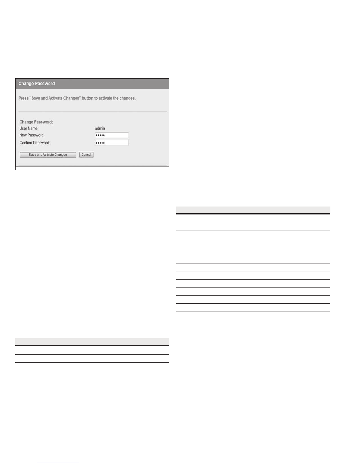
User Manual MN032EN
Effective October 2017
Changing your password
You can change your password by clicking Change Password on the
menu and entering the new password in both password fields. Click
Save and Activate Changes to change your password. Passwords
must be at least eight characters.
Figure 42. Change password
215U-2 802.11
wireless I/O and gateway
User management
Users with Admin privileges can click User Management on the
menu to configure access to the module (see Figure 43). An Admin
can add new users, change user passwords, or retire (deactivate)
user access. The Admin assigns each user a “role” which limits the
functions available to them according their operational needs.
ote:N You cannot delete individual users from the system, but can deactivate
user access by “retiring” the user. If you need to delete all user information
from the module and restore the factory default user settings, see “Restoring
the factory default user configuration” on page 42.
There are three user roles:
•
Operator—Can view information on the device, but cannot
change configuration.
•
Manager—Can view information and change the device
configuration, but cannot modify the list of users allowed to
accessthe device.
•
Admin—Has all of the permissions of a Manager, plus the
abilityto modify the user list, user passwords, and access
levels.(All users can change their own passwords.)
The module comes from the factory with two default users.
Table 14. Users
Default user name Default password Role
admin admin Admin
user user Manager
Table 15. Access privileges
Menu item Operator Manager Admin
Network — Yes Yes
IP Routing — Yes Yes
I/O Mappings — Yes Yes
Fail Safe Configuration — Yes Yes
Serial — Yes Yes
I/O Configuration — Yes Yes
Modbus — Yes Yes
Module Information — Yes Yes
System Tools — Yes Yes
Feature Keys — Yes Yes
Data and Event Log — Yes Yes
Change Password Yes Yes Yes
User Management — — Yes
I/O Diagnostics Yes Yes Yes
Connectivity Yes Yes Yes
Logs and Archives Yes Yes Yes
Home Yes Yes Yes
Access to menu items is restricted by the user’s role, as shown
in the following table. If you click a menu item and do not have
sufficient access privileges, you are prompted to enter a username
and password with the necessary access privileges.
32
EATON www.eaton.com
Page 37
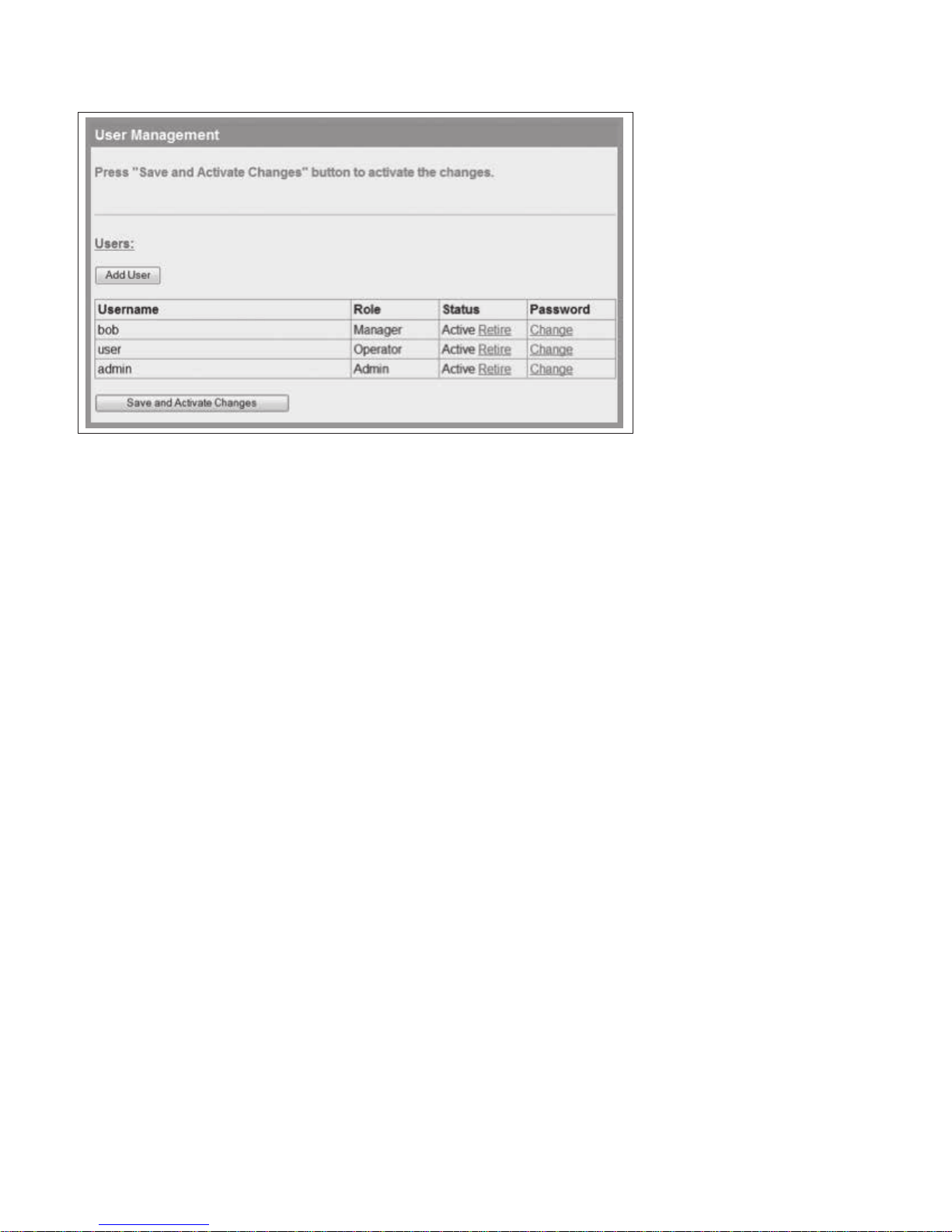
215U-2 802.11
wireless I/O and gateway
Figure 43. User management
User Manual MN032EN
Effective October 2017
To add a user
1. Click User Management on the menu.
2. Click Add User.
3. Enter a username and password, and confirm the password.
Passwords must be at least eight characters.
4. Select a role for the user.
5. Click Create to add the user.
6. To add additional users, repeat steps 2 through 5.
7. When you have finished adding users, click Save and Activate
Changes.
To retire a user
1. Click User Management on the menu.
2. In the Status column for the user, click Retire.
3. Click OK to confirm.
The user’s status changes from “Active” to “Retired.”
4. Click Save and Activate Changes.
This disables access to the module by the retired user.
To change a user password
1. Click User Management on the menu.
2. In the Password column for the user, click Change.
3. Enter a new password for the user and confirm the new
password.
4. Click Apply.
5. Click Save and Activate Changes.
Recovery after lost admin password
If you lose the password for your admin account you can revert to
the default password by resetting the device configuration to factory
default. Refer to the section [Restoring the factory default settings]
on p42.
EATON www.eaton.com
33
Page 38
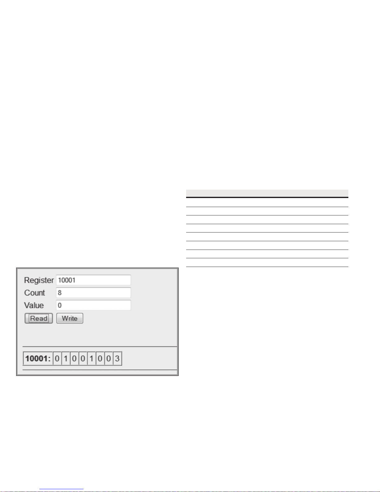
User Manual MN032EN
Effective October 2017
Diagnostics
This chapter describes network diagnostic tools and information
available from the module’s Web-based configuration utility. To
access this utility, see “Connecting and logging on” on page 15.
IO diagnostics
Click IO Diagnostics from the home page of the Web-based
configuration utility to read and write I/O store registers within
the module.
To read a register location, enter an address location (for example,
10001 for digital inputs), enter a count (number of consecutive
registers), and then click Read (see Figure 44). The returned address
location and the returned values appears at the bottom of the page.
To write to outputs, enter the address location, count, and value,
and then click Write. You will see the outputs change to the value
you entered. For example, write to Register 1 with a count of 8 and
a value of 1 will turn all the local digital outputs on. Write to Register
40001 with a count of 2 and a value of 49152 will set the two local
physical analog outputs to 20 mA.
ote:N If the value “~“ appears at the bottom of the page when reading a
register, it indicates that the register has been initialized to the “Invalid” state
through the fail-safe configuration and therefore has no value (not even zero).
A mapping will only be sent when all registers have a value. To set
an initial value for registers upon startup, use the Fail-safe Block
Configuration menu in the Web-based configuration utility or use
the MConfig utility (see “Fail-safe blocks” on page 15). If there
is a mapping configured and any one of the source register values
has the value “~“ the mapping will not be sent (see “Invalid register
state” on page 15).
Using the I/O Diagnostics page, you can check the register locations
for the “~“ values and even write values if required. If you see the
value “3” when reading the status of the DIO on the module it
indicates that the DIO is being used as an output in the “on” state.
215U-2 802.11
wireless I/O and gateway
Watchdog error log
The module uses a various processes to control aspects of its
internal functions, such as radio operation, I/O functionality, and
Modbus communications. Each process runs independently, and
can interact with the other processes to provide a robust wireless
I/O product.
All processes are monitored by an internal “watchdog.” If a
processes has a problem and stops running, the watchdog will
identify the problem and restart the module. The watchdog also
creates a text file showing which process had the problem.
This text file is stored in a directory called ”dog” off the main root
IP address of the module. To display this text file in your browser,
enter http://<Device IP Address>/operator/.
If the watchdog directory continues to show text files, it may
indicate a problem with the module or its configuration. If this
happens, save the module configuration (see “System tools” on
page 28) and the list of watchdog files, and then contact Eaton
technical support.
The following table describes the different watchdog processes.
Table 16. Watchdog process
Watchdog process
A00 Internal process monitor
A01 I/O processing application
A02 Fail-safe manager application
A03 Modbus application
A04 I/O mapping application
A06 AODV meshing protocol application
A07 Data logging application
A15 Warm restart backup
Figure 44. I/O diagnostics
Register Register address location.
Count Number of consecutive registers, starting from the
register location specified in the Register field.
Value Value to be written.
Read To read a register location, enter an address location
(for example, 10001 for digital inputs), enter a count
(number of consecutive registers), and then click Read.
Write To write to outputs, enter the address location, count,
and value, and then click Write.
Module information registers
Certain registers in the module show modules characteristics, such
as the serial number, firmware version, and so on. This information is
available on the home page of the module’s Web-based configuration
utility. However, having the information available in registers allows
a host system to read the values via Modbus, if Modbus has been
activated.
•
Register 30494, 30495 and 30496 = Module serial number
•
Register 30497, 30498 and 30499 = Module firmware version
•
Register 30500 = Firmware patch level
34
EATON www.eaton.com
Page 39

215U-2 802.11
User Manual MN032EN
wireless I/O and gateway
Expansion I/O error registers
The 215U-2 has diagnostics registers allocated for each expansion
I/O module. These registers indicate the module type, error counts,
error codes, and so on. Each expansion I/O module has the following
registers.
•
30017 + Offset = Modbus error counter (number of errors the
modules has had)
•
30018 + Offset = Last 115S status code/Modbus error code
Table 17. Expansion I/O Status Codes
Dec code Hex code Name Meaning
1 0001 No Response No response from a poll
2 0002 Corrupt/invalid Corrupt or invalid data
3 0003 CRC Fail CRC error check does not match the message. Indicates this a
4 0004 Response did not match request The response heard was not the correct ID; possibly heard other
5 0005 Message type did not match request The response heard did not match the requested poll (different
129 0081 Problem accessing local memory Could not access register location, possibly because the register
> 32768 ??01- ??0B Standard Modbus Error Codes As per page 51
•
30019 + Offset = Modbus Lost Link Counter (number of Communication Errors)
•
30020 + Offset = Modbus Module Type:
different message or possible data corruption.
RS-485 traffic.
command response); possibly heard other RS-485 traffic.
isnot initialized.
dec 257 (101 hex) indicates a 115S-11
dec 513 (201 hex) indicates a 115S-12
dec 769 (301 hex) indicates a 115S-13
Register 30018 will display one of the following 115S status
codes(hexadecimal code 1–5 and 81), as well as displaying
Modbus response codes similar to what is shown on page 55,
but with the most significant byte being one of the following
values, 82, 84, 8F or 90.
Effective October 2017
Diagnostic registers—device statistics
Commonly used statistics for diagnostics and system monitoring can
be accessed in onboard I/O Registers. via an external device using
any of the supported I/O transfer protocols (WIB, MODBUS).
When statistics logging is enabled, the statistics are logged to
RSSI: The signal strength to the upstream device
(Repeater or base station)
Connected Time: The amount of time the current upstream
connection has been established (in hours)
Generation Count: The number of times the current upstream
connection has been established. This
value is 1 when the device first connects,
then if the link is lost it increments once
each time the link is re-established. Note
that if both the upstream device and the
local device are re-started, the Generation
count will reset to 1. If only one device is
re-started, then the generation count is
designed to be retained.
Upstream IP Address: The address of the Upstream device
(Base, Repeater or Manual Mode Access
Point).
The following information about the device uptime is available for all
devices:
Module Uptime: The amount of time the module has been
powered on. You can compare this against
the connected time to determine if the
module has been losing link.
Analog Input Registers. These are listed in detail in “Input registers”
on page 45.
Statistics registers provide the following information about the
upstream connection (Towards the base station). If the module is
configured as a base, or configured in manual mode without any
Client functionality, then these registers will be zero.
Channel and radio statistics are available for all devices, and are
available averaged over the last minute, last hour, and last 60-hour
periods.
Channel Utilization: This is the percentage of time the
radio channel has been busy with radio
transmissions from any devices within
receiving range of this device.
Background Noise: This is the background noise level on
the radio channel when the radio is not
receiving valid data.
Retried Transmissions: This is the percentage of radio
transmissions that were successful, but
required at least one re-transmission before
they were acknowledged. This statistic does
not apply to broadcast transmissions, which
are not acknowledged.
Failed Transmissions: This is the percentage of transmissions that
were unsuccessful due to not receiving an
acknowledgement message to any of the
re-transmissions. This statistic does not
apply to broadcast transmissions, which are
not acknowledged.
EATON www.eaton.com
35
Page 40

User Manual MN032EN
Effective October 2017
Statistics registers also record information about downstream
connections. These registers are used by all devices that have
downstream connections—Base station, Repeater, and Manual
Mode Access Points. For Manual Mode clients, and for Field Station
devices, these registers are unused and available as general purpose
storage.
215U-2 802.11
wireless I/O and gateway
RSSI List: This is a block of 255 register locations. For each
downstream device, the last byte of the device’s IP
address is used to determine which location to store
the signal strength. For example, a downstream
device with IP Address 192.168.0.199 will have its
RSSI stored in I/O register offset 199. If no device is
connected with the IP address, the register has the
value Zero.
Monitoring communications
Monitor IP comms on Ethernet port
Click Monitor IP Comms on the home page of the Web-based
configuration utility to view the IP communication data frames.
From here you can decode the data frame and read the transmitted
and received I/O values.
ote:N This data is output in tcpdump format.
36
EATON www.eaton.com
Page 41
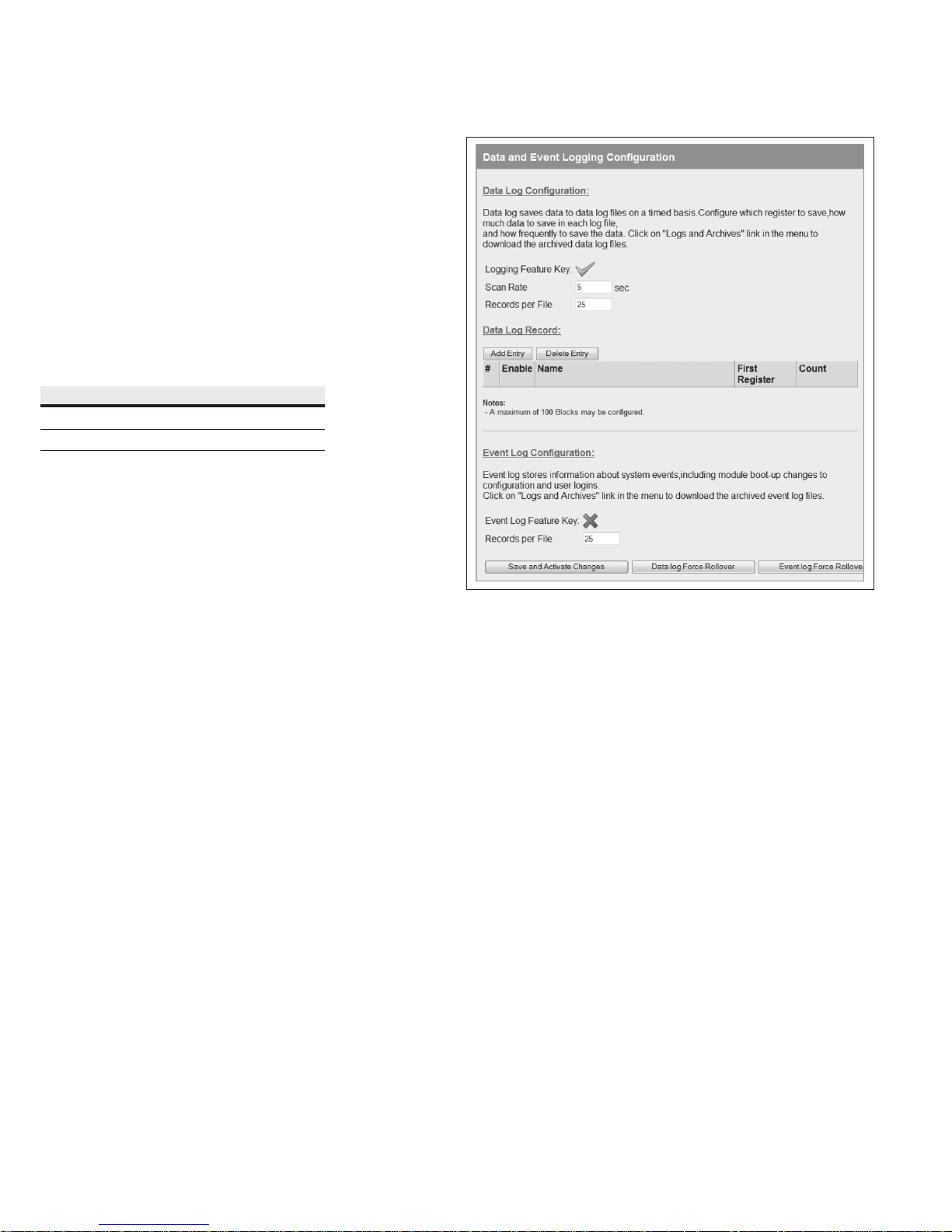
User Manual MN032EN
Effective October 2017
Data logging
The data logging feature allows you to record the status of I/O
registers on a regular basis. Data is saved to non-volatile memory,
and can be retrieved at a later time. You can enable data logging
on 215U-2 version 2.0 modules with the purchase of a feature key
license (see “Feature license keys” on page 31).
Data is logged to an internal data file in “.csv” format. Each row of
the file is a single record, consisting of a timestamp and values of
all of the configured log items at that time. When the file reaches a
configured maximum number of rows, the file is “rolled,” that is, the
file is compressed and archived and a new log file is created.
The amount of memory available for storing logged data depends
on the device type. The available data logging memory is indicated
in the log files. When the memory is full, the oldest data log file is
deleted.
Table 18. Data logging
Device Data logging memory
215U-2 200 KB
215U-2 XM 200 MB
Configuring data logging
To configure data logging, you need to specify how frequently the
data is to be stored, what data is to be stored, and the maximum
number of records stored in each log file. Click Data and Event
Log on the home page of the Web-based configuration utility to
configure these settings (see Figure 46).
ote:N You need Administrator or Manager privileges to configure data and
event logging.
215U-2 802.11
wireless I/O and gateway
Figure 45. Data and event logging configuration
Data log configuration
Scan Rate Enter the rate that you want data to
be recorded (fastest rate is every 5
seconds).
Records per File Enter the maximum number of records
you want in a file (up to 3,000 records
per file). When the maximum is
reached, the file is archived and a new
data log file is created.
Data Log Record Each entry in this table specifies a
block of registers to be included in the
log. To add an entry, click Add Entry
and fill in the Name, First Register, and
Count information. Select the Enable
checkbox to enable data logging for
the block. You can configure up to 100
register blocks. Use Delete to remove
an entry that you no longer want.
For a configuration example, see
Figure 47 and Table 20.
The configuration example in see Figure 47 will log six registers in
each log record. Table 20 shows an example of the logged data for
this configuration.
Enable When this checkbox is selected,
data logging is enabled for this block
of registers. When it is cleared, a
placeholder symbol “-” is stored to the
log file.
Name Name to appear in the column heading
within the log file to identify data for
this entry. If no name is entered, the
register number is used as the column
heading.
First Register Address of the first register to be
logged.
Count Number of registers to be logged.
Event Log Configuration These settings apply only to modules
that have the 915U-AT (Audit Trail)
feature key enabled. Event Logging is
discussed in a separate document.
38
EATON www.eaton.com
Page 42
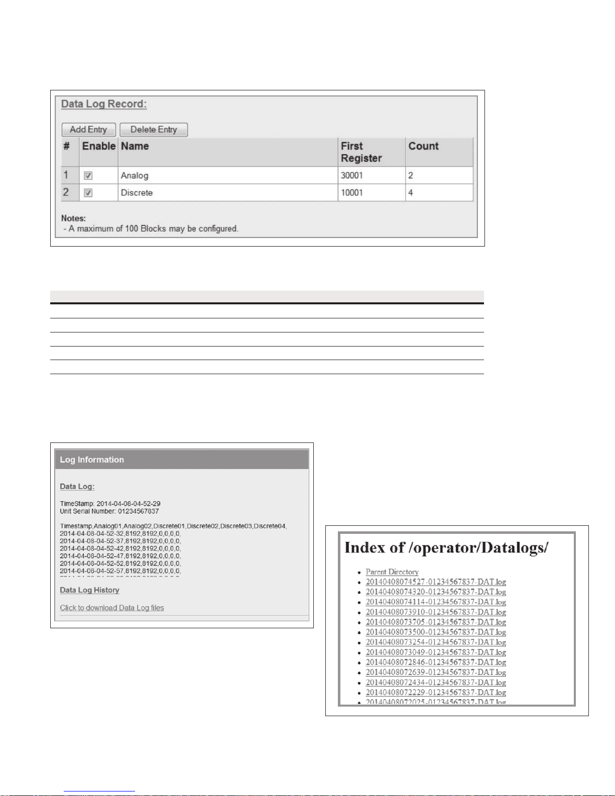
215U-2 802.11
wireless I/O and gateway
Figure 46. Data log record
Table 19. Data log example
Timestamp A nalog 01 Analog02 Discrete01 Discrete02 Discrete03 Discrete04
2014-04-08 03:4 3:47 8192 8192 0 0 0 0
2014-04-08 03:43:52 8192 8192 0 0 0 0
2014-04-08 03:43:57 8192 8192 0 0 0 0
2014-04-08 03:44:02 819 2 8192 0 0 0 0
2014-04-08 03:44:07 819 2 8192 0 0 0 0
User Manual MN032EN
Effective October 2017
Viewing current data
To view the latest logged data, click Logs and Archives on the
home page of the Web-based configuration utility. The latest data is
shown in a “.csv” format on the screen.
Figure 47. Log information
Retrieving logged data
The module supports remote retrieval of files via HTTP and FTP, as
well as local retrieval of files via USB flash drive.
To retrieve logged data files via HTTP
1. Click Logs and Archives on the home page of the Web-based
configuration utility.
2. Click the link “Click to download data log files.”
This displays a listing of all of the stored data log files. Files are
named with the time and date created and the module serial
number, in the format yyyymmddhhmmss-nnnnnnnnnnn-DAT.log.
Figure 48. Data log listing
3. Right-click the file that you want to retrieve.
EATON www.eaton.com
39
Page 43
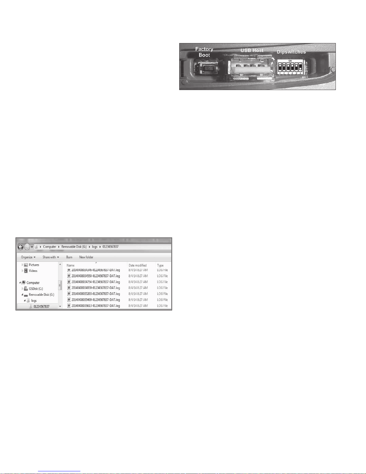
User Manual MN032EN
Effective October 2017
4. Click Save Target as to save the file to your local computer.
To retrieve logged data files using a USB drive
1. Make sure that the USB drive is formatted for a FAT file system.
This is the normal file system on USB drives.
2. Create a directory named “logs” (all lowercase) on the
USB drive.
3. Using a small screwdriver, open the hatch on the side of
the module.
4. Plug the USB drive into the USB Host port (see Figure 50).
Within 10 seconds, the module should recognize the USB drive
and the OK LED should flash red-green. If the module does not
recognize the USB drive, check to make sure that the drive is
formatted with FAT file system and that it contains a directory
named “logs”.
When the USB drive is recognized, the module copies the data
log files to the USB drive. Once all files are copied, the OK LED
turns solid green. The data log files are not deleted from the
module when they are copied to USB drive.
If the module encounters an error or if the USB drive does not
have sufficient space to fit all of the files, the OK LED turns solid
red to indicate a failure. Remove the USB drive and try another
one until the files are successfully transferred and the OK LED
turns green.
215U-2 802.11
wireless I/O and gateway
Figure 49. USB port
5. Remove the USB drive from the module USB port.
The log files are contained in a directory under the “logs”
directory. This subdirectory is named with the module device
name, or the module serial number if no device name was
configured for the module. The device name is configured on the
Module Information configuration page. The following example
shows the contents of a USB drive after retrieving log files
from a module. In this example, the module serial number is
01234567837.
Figure 50. Log file directory on USB drive
You can leave the files on the USB drive. The next time you plug in
the USB drive, only the new files are retrieved from the module.
You can also use the same USB drive to retrieve data from multiple
modules. The data for each module is stored in a separate directory.
If you configure your modules with a device name, the data is
stored in a directory with that name. Take care that each module has
a unique device name. Data from modules with the same device
name will be stored in the same directory.
40
EATON www.eaton.com
Retrieving stored log file data
The log files are stored in comma-separated-value (.csv) format.
To increase storage space, each log file is compressed using the
Tar-Gzip method when it is stored to internal flash memory. The log
files can be opened and the compressed .csv files recovered using
an archive manager, such as 7-Zip, that can operate with Tar-Gzip
(.tgz)files.
Page 44

215U-2 802.11
wireless I/O and gateway
User Manual MN032EN
Effective October 2017
Specications
Specifications for the 215U-2 are provided in the following table.
Table 20. 215U-2 specifications
Item Specification
Input/Output
Discrete Input 8 Digital I/O (1–4 Configurable as Pulsed Input or Output)
Discrete Output 8 Digital I/O (1–4 Configurable as Pulsed Input or Output)
Analog Inputs 4 AI (2 Differential, 2 Single Ended)
Analog Output 2 AO (Sourcing)
Ethernet Ports
Ethernet Port 10/10 0base®; RJ-45 Connector, IEEE 802.3
Link Activity Link, 100Base via LED
Serial Ports
RS-232 Port EIA-562 (RJ-45 Connector)
RS-485 Port 2-Pin Terminal Block, Non-isolated
Data Rate (Bps) 1200, 2400, 4800, 9600, 14400, 19200, 38400, 57600, 76800, 115200, 230400 bps
Serial Settings 7/8 Data Bits; Stop/Start/Parity (Configurable)
Protocols and Configuration
Protocols Supported TCP/IP, UDP, HTTP, FTP, TFTP, Telnet, Modbus RTU Master/Slave, Modbus-TCP Client/Server, WIB I/O
User Configuration All User Configurable Parameters via HT TP
Configurable Parameters Unit details, I/O mappings and parameters. For configuration details, see in this manual.
Security Data Encryption: 802.11 Encr yption Standards to WPA-2 with 128-bit AES encryption
LED Indication/Diagnostics
LED Indication
Reported Diagnostics Connectivity Information/Statistics, System Log File
Compliance
EMC EN 301 489-17
Hazardous Area UL Class 1, Division2; ATEX; IECE x Na IIC (ATEX, IEC Ex Pending)
Safety EN 62368 (RoHS Compliant, UL Listed)
Radio FCC Part 9 0, AS/NZS 4268, EN 300 328
General
Size 5.91" x 7.09" x 1.38" (180mm x 150mm x 35 mm)
Housing IP20 Rated PolyCarbonate
Mounting DIN Rail
Terminal Blocks Removable; Max Conductor 12 AWG 0.1in
Temperature Rating –40 to +160 °F (–4 0 to +70 °C)
Humidity Rating 0–99% RH Non-condensing
Weight 1.1 lb (0.5 kg)
Power Supply
Nominal Supply 15 to 30 Vdc; Under/Over Voltage Protection
Battery Supply 10.8 to 15 Vdc
Average Current Draw 230 mA @ 12 V (Idle), 150 mA @ 24 V (Idle)
ote:N Specifications subject to change.
1
Maximum Distance 4000 ft (1219.2 m).
On-State Voltage: < 2.1 Vdc
Wetting Current: 3.3 mA
Max I/ P Pulse Rate: DI 1/2: 50 kHz; DI 3/4: 1 kHz
Min I/P Pulse Width: DI 1/2: 10 μsec; PI 3/4: 0.2 msec
On-State Voltage: DO Max, < 0.5 V
Maximum Current: 200 mA
Max O/P Pulse Rate: PO Max Rate, 1 kHz
Current Range: 0 –24 mA
Current Resolution: 14 bits
Accuracy (Current): 0.1%
Voltage Input Range: AI 1/2: 0–20 V, AI 3/4: 0–5 V
Voltage Resolution: 14 bits
Accuracy (Voltage): 0.1% full scale
Current Range: 0 –24 mA
Current Resolution: 13 bits
Accuracy (Current): 0.1% (20 μA)
1
Modbus TCP/ RTU Gateway
Embedded Modbus Master/Slave for I/O Transfer
Power/OK; Wireless Link/Activity; RS-232; RS-485; Digital I/O; Analog I/O Status
2
(2.5 mm2)
EATON www.eaton.com
41
Page 45
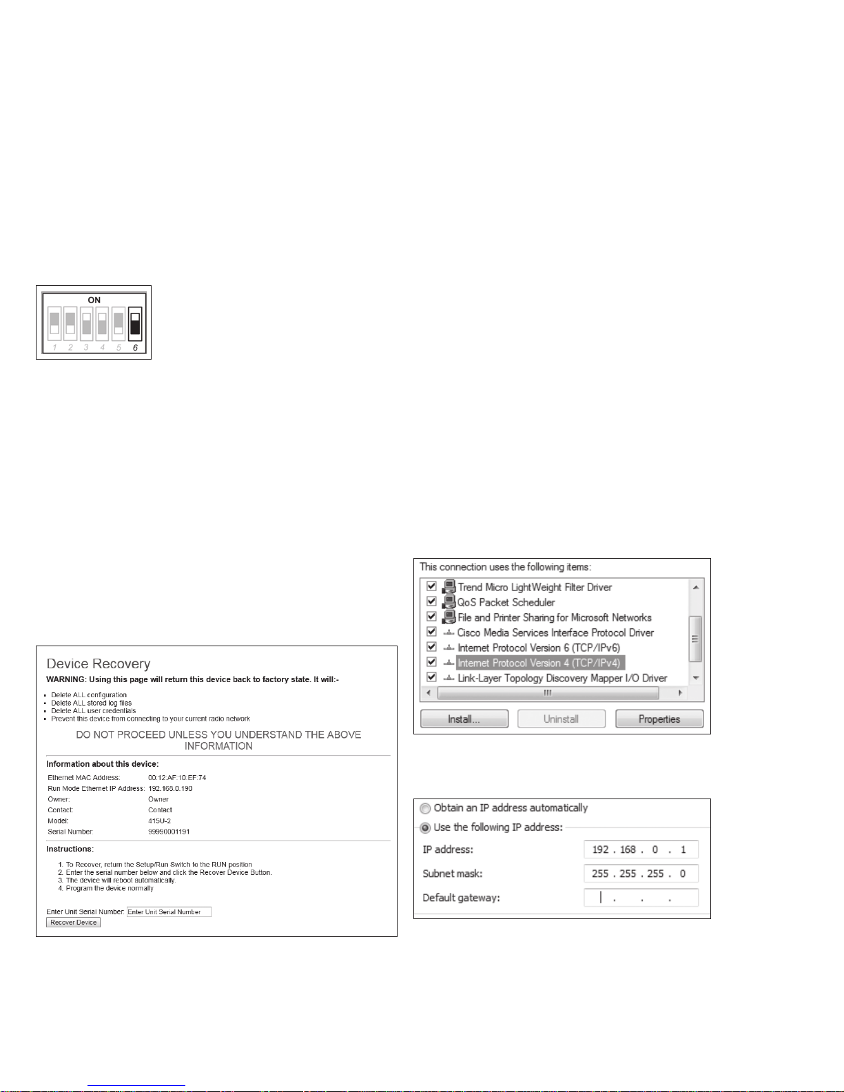
User Manual MN032EN
Effective October 2017
Troubleshooting
215U-2 802.11
wireless I/O and gateway
Restoring the factory default connection settings
You can use this procedure to restore the device to the factory
default configuration if you don’t have access to credentials to
access the device. You will need a USB cable and USB driver files
installed on your computer to complete this procedure (see below).
ote:N The following procedure will delete all configuration, user accounts
and log files from the device.
1. Open the side configuration panel on the module, and set DIP
switch #6 to “on.”
2. Power cycle the module.
When the 215U-2 is powered on with DIP switch #6 set to “on,”
the module goes into a special mode that allows you to restore the
device to factory configuration.
Once the device has powered up, connect to the USB port. The
USB port is located on the bottom side of the module. (Refer
Figure 11 “Bottom Panel Connections”). To connect, you need an
USB cable (USB-A to USB-B) for connecting from your computer
to the module’s USB-B port . If this is the first time you have used
your computer to connect to an ELPRO device through the USB
port, then you will need to download the USB driver file from the
product’s internet website. This is available from the same location
that you downloaded this user manual. The filename is “ElproUSB.
inf”.
Important: Remember to set DIP switch #6 to “off” and power
cycle the module to return to normal operation after you have
completed configuration. Otherwise, the module will continue to
boot into the default IP address
Configuring PC networking settings for Ethernet
and Wireless
If you are unable to connect to the device through either the
Ethernet or Wireless connection, use this guide to ensure you have
your PC configured correctly.
ote:N To connect Wirelessly you need to have first configured the module to
accept the PC wireless connection. See section “Connecting your device to
an existing 215U-2 network” on page 12 for more information.
(The following description is for Windows 7. Other operating systems
have similar settings)
1. On the PC, open Control Panel, then select Network and
Sharing Center.
2. Click “Change Adapter Settings” on the left of the screen. You
should see a list of available network adapters.
3. Find the correct network connection in the list. For Ethernet,
this will normally be “Local Area Connection”. For Wireless
connection, this will normally be “Wireless Network
Connection”
4. Right click on the network connection and select Properties
from the context menu.
5. Select “Internet Protocol Version 4 (TCP/IPv4)” and click on
Properties.
Open your web browser, and enter the IP address 192.168.111.1. You
should see the following page:
Enter the device serial number (as an additional precaution against
accidentally deleting the device), Set DIP switch 6 to “off”, and click
“Recover Device”. Click “OK” to start device recovery. Once you
have clicked OK, disconnect the USB Cable. Once the device has
restarted, you can plug the USB cable back in to access the device
using the default credentials.
6. On the General tab, select Use the following IP address: and
enter IP address 192.168.0.1, and subnet mask 255.255.255.0,
then click OK.
ote:N If you have configured your 215U-2 network to provide IP addresses via
DHCP, you should select “Obtain IP address automatically”.
7. Verify the Ethernet connection to the module by using the “ping”
command. Start a command window (click Start menu and type
“command” into the search box). At the command prompt, type
“ping <IP Address>. If you have restored the default connection
settings, then the IP address will be the address printed on the
module’s side label.
42
EATON www.eaton.com
Page 46
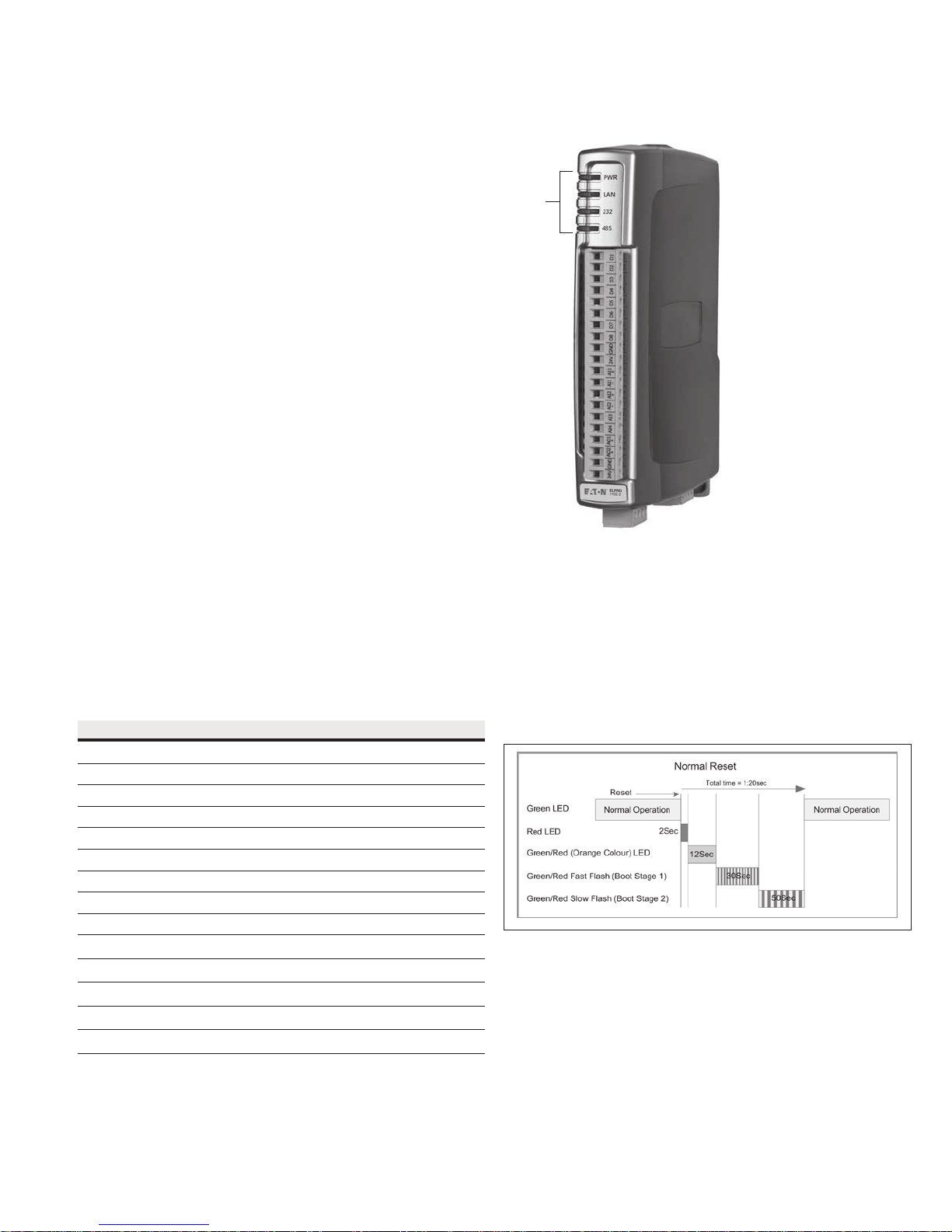
215U-2 802.11
wireless I/O and gateway
Configuring PC networking settings for USB
You should normally be able to connect to the USB without any
additional setup. The 215U-2 is configured to automatically assign IP
address to devices connecting to the USB through DHCP. If you are
unable to connect, then you may need to set your PC to request the
IP address from the 215U-2.
(The following description is for Windows 7. Other operating systems
have similar settings)
1. On the PC, open Control Panel, then select Network and
Sharing Center.
2. Click “Change Adapter Settings” on the left of the screen.
You should see a list of available network adapters.
3. Find the correct network connection in the list. This will be
named “Local Area Connection XX” and have description
“Elpro 215U-2 USB Ethernet/RNDIS”.
4. Right click on the network connection and select Properties from
the context menu.
5. Select “Internet Protocol Version 4 (TCP/IPv4)” and click on
Properties.
6. On the General tab, ensure Obtain IP Address automatically
is selected.
7. Verify the Ethernet connection to the module by using the “ping”
command. Start a command window (click Start menu and type
“command” into the search box). At the command prompt, type
“ping 192.168.111.1”.
LED function
User Manual MN032EN
Effective October 2017
LEDs
Front panel LEDs
When the module is initially connected to power, it performs
internal setup and diagnostics checks to determine if it is
operating correctly. These checks take approximately 80 seconds.
The following table shows how the LEDs appear when the module
is operating correctly.
Table 21. Front panel LEDs
LED Condition Meaning
PWR Green System OK
PWR Red System boot (initial or system fault)
PWR Orange Start of system boot
PWR Fast Flash System boot, stage 1
PWR Slow Flash System boot, stage 2
RF Green RF Link established
RF Flash Off from Green Radio Receive (RF Link established)
RF Flash Green from Off Radio Receive (No RF Link)
RF Orange Flash Radio transmit
232 Green
232 Red
232 Orange
485 Green
485 Red
Transmitting RS
Receiving RS-232 data
Transmitting and receiving RS-232 data
Transmitting RS-485 data
Receiving RS-485 data
-232 data
LED boot sequence
Upon reset, the PWR LED appears solid red for about 2 seconds
(system boot), followed by 12 seconds of Orange (start of system
boot process). The PWR LED then fast flashes between red and
green for 30 seconds (stage 1 of system boot process) followed
by a slow flashes for 50 seconds (stage 2 of system boot process).
At the end of the boot sequence the PWR should appear solid
green. The time periods are approximate, and depend on the
hardware and firmware revisions.
Figure 51. Boot sequence
EATON www.eaton.com
43
Page 47
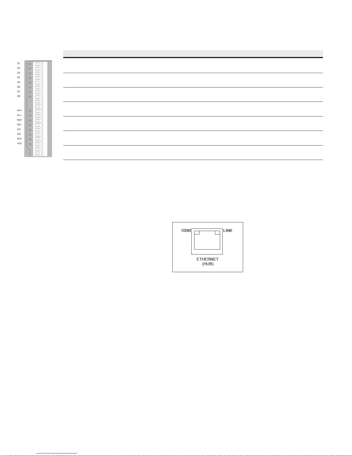
User Manual MN032EN
Effective October 2017
Input and output LEDs
LED indicator Condition Meaning
D 1–8 Orange Digital input is on
D 1–8 Flashing Orange -(Long On) Update failure (fail-safe state is on)
D 1–8 Flashing Orange -(Long Off) Update failure (fail-safe state is off)
AI 1 and 2 + Orange Analog input current indication
AI 1 and 2 – Orange Analog input voltage indication
AI 3 and 4 Orange Analog input current or voltage indication
AO1 and 2 Orange Analog output current indication
215U-2 802.11
wireless I/O and gateway
Digital inputs
LEDs display the status of each of the eight DIOs when used as
inputs. If the LED is on, it indicates that the input ison.
Digital outputs
When the DIOs are used as outputs, the LEDs display the status
of each of the digital outputs. If an LED is on, it indicates that the
output is on. The LEDs also indicate if the output is in a fail-safe
state by flashing at different rates. If an LED is mostly on (long
on) it indicates that the fail-safe state shown on the Digital Output
Configuration page is on. If an LED is mostly off (long off) it indicates
that the fail-safe state shown on the Digital Output Configuration
page is OFF. See “Fail-safe blocks” on page 15 for details.
Analog inputs
There are two LEDs for each differential analog input. The first LED
(+) is used to indicate that the analog input is reading a current
(mA). The second LED (–) indicates that the input is reading voltage.
Each of the analog input LEDs will come on when there is a signal
present at the analog input.
Analog outputs
Each analog output has an LED in series that indicates the output
current by increasing or decreasing the intensity of the LED. For
example, at 4 mA the LED appears dimmed, and at 20 mA, the LED
appears bright.
Ethernet LEDs
On the end plate, the Ethernet socket incorporates two LEDs that
indicate the Ethernet status.
•
100 M—Green LED indicates presence of a 100-Mbps Ethernet
connection. With a 10-Mbps connection, the LED is off.
•
LINK—Orange indicates an Ethernet connection. The LED briefly
flashes with activity.
Figure 52. Ethernet socket
44
EATON www.eaton.com
Page 48

215U-2 802.11
wireless I/O and gateway
User Manual MN032EN
Effective October 2017
Register memory map
Digital output registers (coils)
Address range Description
0001 – 0008 Local DIO1–DIO8 as digital outputs
0009 – 0020 Spare
0021 – 0 400 Space for locally attached 115s expansion I/O modules. Twenty register per module address, maximum number of modules is 19.
0401 – 6000 General purpose bit storage used for: Staging area for data concentrator; Fieldbus mappings storage; Force mapping registers
6001 – 10000 Not Available
Digital input registers (bits)
Address range Description
10001 – 10008 Local DIO1–DIO8 as digital inputs
10009 – 10020 Set point status from analog inputs 1 through 12
10021 – 10 40 0 Space for locally at tached 115s expansion I/O modules. Twenty register per module address, maximum number of modules is 19.
104 01 – 16 00 0 General purpose bit storage used for: Staging area for data concentrator; Fieldbus mappings storage;
16001 – 20000 Not Available
Input registers (words)
Address range Description
30001 – 30004 Local AI1–AI4 (analog inputs, current mode)
30005 Local supply voltage (0 –40 V scaling)
30006 Local 24 V loop voltage (0–40 V scaling)
30007 Local battery voltage (0–40 V scaling)
30008 115S supply voltage (0 –40 V scaling)
30009 – 30010 Local AI1, AI2, Voltage Mode. 0-24V Scales to 0-24mA.
30011 – 30012 Local AI3, AI4, Voltage Mode. 0-5 V Scales to 0-20mA
30013 – 30016 Local pulse input rates: PI1–PI4
30018 – 30020 Spare
30021 - 30400 Space for locally attached 115s expansion I/O modules. Twenty registers per module address, maximum number of modules is 19.
30401 RSSI: When configured as a Remote, Repeater, or Manual Client, the RSSI of the connected upstream device in –dBm
30402 Connected Time: When configured as a Remote, Repeater, or Manual Client, the time (in hours) that the connection to the upstream device has
30403 Generation Count: When configured as a Remote, Repeater, or Manual Client, the generation count of the connection to the upstream device.
30404 – 30405 Upstream IP Address: When configured as a Remote, Repeater, or Manual Client, the IP Address of the upstream device.
30406 Radio 802.11 Channel number (1 – 13)
30407 – 30408 Radio Transmit Frequency (in MHz). 32-bit. Most significant word at lower (odd) address.
30409 – 30410 Radio Receive Frequency (Same as Transmit Frequency)
30 411 Module uptime: The time (in hours) that this module has been up and running
30 412 Channel Utilization % (average of last 60 seconds)
30413 Background Noise (average of last 60 seconds)
30414 Tx retry % (average of last 60 seconds): The percentage of total transmissions that required at least one retry
30 415 Tx failed % (average of last 60 seconds): The percentage of total transmissions that failed to get an acknowledgement after all retries exhausted.
AI1 and AI2: 4–20 mA differential
AI3 and AI4: 4–20 mA sink
been made.
This is the number of times the connection has been lost and re-established
Most Significant Byte High byte of Register 304 04
Second Byte Low byte of Register 30404
Third Byte High byte of register 30405
Least Significant Byte Low by te of register 30405
EATON www.eaton.com
45
Page 49

User Manual MN032EN
Effective October 2017
Address range Description
30416 – 30419 Channel Utilization, Background noise, Tx Retry % and Tx Failed % (average of the last 60 minutes)
30420 – 30423 Channel Utilization, Background noise, Tx Retry % and Tx Failed % (average of the last 60 hours)
30424 – 30493 Spare - General purpose word storage used for: Staging area for data concentrator; Fieldbus mappings storage;
30494 – 30500 Internal information registers: serial number, firmware version and patch level
30494 First four digits of serial number (Encodes Manufacture Month & Year
30495 Next three digits of serial number (Encodes Manufactured Firmware version)
30496 Remaining four digits of the serial number
30497 First part of Current Firmware version
30498 Second par t of Current Firmware version
30499 Third part of Current firmware version
30500 Patch Level of current firmware version
30501 – 32000 General purpose word storage used for: Staging area for data concentrator; Fieldbus mappings storage;
32001 - 32255 RSSI List: When configured as an Base, Repeater, or Manual AP. The RSSI of each connected downstream is added to an I/O register according to
the last byte of that device’s IP Address. For example, a downstream device with IP Address 192.168.0.199 will have its RSSI stored in I/O register
32000 + 199 = 32199. If no device is connected with that IP address, the corresponding register has the value Zero.
32256 – 36000 General purpose word storage used for: Staging area for data concentrator; Fieldbus mappings storage;
36001 - 36008 Local pulsed inputs 1–4, big endian format Most significant word at lower/odd address
36009 – 360 40 Spare space for 32-bit register values
36041 – 38000 Not Available
38001 - 38032 Local analog inputs as floating point values. ModScan format (sign + exponent + most significant 7 bits of significant at even/higher addressed
location; lower 16 bits of significant at lower/odd addressed location)
(example: Analog input 1 at 12.3 mA gives registers 38001=CCCD, 38002=4144)
38033 – 38040 Spare space for floating point values
38041 – 40000 Not Available
wireless I/O and gateway
215U-2 802.11
Output registers (holding registers)
Address range Description
40001 – 40002 Local AO1 and AO2:analog outputs
40003 – 40020 Spare
40021 – 40400 Space for locally attached 115s expansion I/O modules. Twenty registers per module address, maximum number of modules is 19.
40401 – 46000 General purpose word storage area used for: Staging area for data concentrator; Fieldbus mappings storage
46001 – 46008 Local pulsed outputs 1–4. Big endian format. Most significant word at lower/odd address
46009 – 46040 Spare 32-bit registers
460 41 – 48000 Not Available
480 01 – 48004 Local analog outputs as floating point values. ModScan format (sign + exponent + most significant 7 bits of significant at even/higher addressed
480 05 – 48040 Spare space for floating point values
48041 Onwards Not available
location) Lower 16 bits of significant at lower/odd addressed location
(example: Analog output 1 at 12.3 mA gives registers 48001=CCCD, 48002=4144)
46
EATON www.eaton.com
Page 50

215U-2 802.11
wireless I/O and gateway
User Manual MN032EN
Effective October 2017
Expansion I/O registers
Adding expansion I/O modules to the 215U-2 will automatically add
the I/O from the 115S modules to the internal 215U-2 I/O store. To
calculate the register location in the I/O store, find the address of
the I/O point in the tables in this appendix, and then add the offset.
The offset is the Modbus address, multiplied by 20.
Examples:
•
Digital input #1 on an 115S-11 with address 5 would be: (5x20)
+10 0 01 = 10101
•
Digital output #2 on an 115S-11 with address 6 would be: (6x20)
+2 = 122
•
Analog input #3 on an 115S-12 with address 3 would be: (3x20)
+30003 = 30063.
•
Analog output #8 on an 115S-13 with address # 7 would be:
(7x20) + 40007 = 40147
I/O store for 115S-11 expansion I/O modules
I/O store Description
0001 + Offset
0016 + Offset
10001 + Offset
10016 + Of fset
10019 + Offset Modbus Comms Fail indication for this 115S module
10020 + Offset Modbus Comms Fail indication (inverse) for this 115S module
30001 + Offset
30004 + Offset
30005 + Offset
30012 + Offset
30017 + Offset Modbus Error counter for this 115S module
30018 + Offset Modbus Last Error code for this 115S module (see “E xpansion I/O error registers” on page 35.)
30019 + Offset Modbus Lost Link counter for this 115S module
30020 + Offset Module type (0x0101) = 257/error status
400 09 + Offset
40016 + Offset
DIO outputs 1–16
DIO inputs 1–16
115S-11 pulsed input rate 1–4
115S-11 pulsed input count
Pulsed output target 1–8 (1 register per pulsed output)
EATON www.eaton.com
47
Page 51

User Manual MN032EN
Effective October 2017
I/O store for 115S-12 expansion I/O modules
I/O store Description
0001 + Offset
0008 + Offset
10001 + Offset
10008 + Offset
10019 + Offset Modbus Error indication for 115S module
10020 + Offset Detected indication for this 115S module
30001 + Offset
30008 + Offset
30017 + Offset Modbus Error counter for this 115S module
30018 + Offset Modbus Last Error code for this 115S module (see “Expansion I/O error registers” on page 35)
30019 + Offset Modbus Lost Link counter for this 115S module
30020 + Offset Module type (0x0201) = 513/error status
400 09 + Offset
40016 + Offset
I/O store for 115S-13 expansion I/O modules
I/O store Description
0001 + Offset
0008 + Offset
10001 + Offset
10008 + Offset
10019 + Offset Modbus Error indication for 115S module
10020 + Offset Detected indication for this 115S module
30017 + Offset Modbus Error counter for this 115S module
30018 + Offset Modbus Last Error code for this 115S module (see “Expansion I/O error registers” on page 35)
30019 + Offset Modbus Lost Link counter for this 115S module
30020 + Offset Module type (0x0301) = 769/error status
400 01 + Offset
400 08 + Offset
400 09 + Offset
40016 + Offset
DIO outputs 1–8
DIO Inputs 1–8
Inputs AIN 1–AIN 8
Pulsed output target 1–8 (1 register per output)
DIO outputs 1–8
DIO inputs 1–8
Analog output 1– 8
Pulsed output target 1–8 (one register per pulsed output)
215U-2 802.11
wireless I/O and gateway
Physical I/O registers
I/O Input Output
Digital I/O 1 10001 1
Digital I/O 2 10002 2
Digital I/O 3 10003 3
Digital I/O 4 10004 4
Digital I/O 5 10005 5
Digital I/O 6 10006 6
Digital I/O 7 10007 7
Digital I/O 8 10008 8
Analog Input 1 (mA) 30001 —
Analog Input 2 (mA) 30002 —
Analog Input 3 (mA) 30003 —
Analog Input 4 (mA) 30004 —
Input 5 – Local V Supply 30005 —
Input 6 – Local +24 V Analog Loop 30006 —
Input 7 – Local V Battery 30007 —
Input 8 – Local V Expansion I/O 30008 —
Analog Input 1 (Volts) 30009 —
Analog Input 2 (Volts) 30010 —
Analog Input 3 (Volts) 30 011 —
48
EATON www.eaton.com
Page 52

215U-2 802.11
wireless I/O and gateway
I/O Input Output
Analog Input 4 (Volts) 30012 —
Pulse Rate 1 30013 —
Pulse Rate 2 30014 —
Pulse Rate 3 30 015 —
Pulse Rate 4 30016 —
Analog 1 Set point 10009 —
Analog 2 Set point 10010 —
Analog 3 Set point 10011 —
Analog 4 Set point 10012 —
Analog 5 Set point 10013 —
Analog 6 Set point 10014 —
Analog 7 Set point 10015 —
Analog 8 Set point 10016 —
Analog 9 Set point 10017 —
Analog 10 Set point 10018 —
Analog 11 Set point 10019 —
Analog 12 Set point 10020 —
Analog Output 1 — 40001
Analog Output 2 — 40002
Pulsed Input 1 Count 36001-36002 —
Pulsed Input 2 Count 36003-36004 —
Pulsed Input 3 Count 36005-36006 —
Pulsed Input 4 Count 36007-36008 —
Pulsed Input 1 Rate 3 0013 —
Pulsed Input 2 Rate 3 0014 —
Pulsed Input 3 Rate 3 0015 —
Pulsed Input 4 Rate 3 0016 —
Pulsed Output 1 Count — 46001-46002
Pulsed Output 2 Count — 46003-46004
Pulsed Output 3 Count — 46005-46006
Pulsed Output 4 Count — 46007-46008
Analog Input 1 Floating Point (mA) 38001-38002 —
Analog Input 2 Floating Point (mA) 38003-38004 —
Analog Input 3 Floating Point (mA) 38005-38006 —
Analog Input 4 Floating Point (mA) 38007-38008 —
Input 5 – Local V Supply Floating Point 38009-38010 —
Input 6 – Local +24 V Analog Loop Floating Point 38011-38012 —
Input 7 – Local V Battery Floating Point 38013-38014 —
Input 8 – Local V Expansion I/O Floating Point 38015-38016 —
Analog Input 1 Floating Point (Volts) 38017-38018 —
Analog Input 2 Floating Point (Volts) 38019-38020 —
Analog Input 3 Floating Point (Volts) 38021-38022 —
Analog Input 4 Floating Point (Volts) 38023-38024 —
Pulse Rate 1 Floating Point 38025-38026 —
Pulse Rate 2 Floating Point 38027-38028 —
Pulse Rate 3 Floating Point 38029-38030 —
Pulse Rate 4 Floating Point 38031-38032 —
Analog O/P Floating Point — 48001
Analog O/P Floating Point — 48002
Analog O/P Floating Point — 48003
Analog O/P Floating Point — 48004
User Manual MN032EN
Effective October 2017
EATON www.eaton.com
49
Page 53

User Manual MN032EN
Effective October 2017
wireless I/O and gateway
215U-2 802.11
115S serial expansion modules I/O registers
115 S -11 115 S -12 115 S -13
Description Inputs Outputs Inputs Outputs Inputs Outputs
Digital I/O 1 10001 1 10001 1 10001 1
Digital I/O 2 10002 2 10002 2 10002 2
Digital I/O 3 10003 3 10003 3 10003 3
Digital I/O 4 10004 4 10004 4 10004 4
Digital I/O 5 10005 5 10005 5 10005 5
Digital I/O 6 10006 6 10006 6 10006 6
Digital I/O 7 10007 7 10007 7 10007 7
Digital I/O 8 10008 8 10008 8 10008 8
Digital I/O 9 10009 9 — — — —
Digital I/O 10 10 010 10 — — — —
Digital I/O 11 100 11 11 — — — —
Digital I/O 12 10012 12 — — — —
Digital I/O 13 10 013 13 — — — —
Digital I/O 14 10 014 14 — — — —
Digital I/O 15 10015 15 — — — —
Digital I/O 16 10 016 16 — — — —
Analog I/O 1 — — 30001 — — 40001
Analog I/O 2 — — 30002 — — 40002
Analog I/O 3 — — 30003 — — 40003
Analog I/O 4 — — 30004 — — 40004
Analog I/O 5 — — 30005 — — 40005
Analog I/O 6 — — 30006 — — 40006
Analog I/O 7 — — 30007 — — 40007
Analog I/O 8 — — 30008 — — 40008
Pulsed I/O Count 1 30017-30018 30009 — 30009 — 30009
Pulsed I/O Count 2 30019-30020 3 0010 — 30 010 — 30010
Pulsed I/O Count 3 30020-30022 3 0011 — 3 0011 — 300 11
Pulsed I/O Count 4 30023-30024 3 0012 — 30012 — 30 012
Pulsed I/O Count 5 — 30013 — 30013 — 30 013
Pulsed I/O Count 6 — 30014 — 30014 — 30014
Pulsed I/O Count 7 — 30015 — 3 0015 — 30015
Pulsed I/O Count 8 — 30016 — 30016 — 30016
Pulsed I/O Rate 1 30001 — — — — —
Pulsed I/O Rate 2 30002 — — — — —
Pulsed I/O Rate 3 30003 — — — — —
Pulsed I/O Rate 4 30004 — — — — —
Supply Voltage 30033 — 30033 — 30033 —
Analog Loop Supply 30034 — 30034 — 30034 —
All expansion I/O is calculated by adding the of fset to the I/O address in the table. The offset is calculated by multiplying the module address by 20.
For example:
Digital input #1 on an 115S-11 (address 5) would be: (5x20) + 10001 = 10100
Digital output #2 on an 115S-11 (address 6) would be: (6x20) + 2 = 121
Analog input #3 on an 115S-12 (address 3) would be: (3x20) + 30003 = 30063
Analog output #7 on an 115S-13 (address 7) would be: (7x20) + 40007 = 40147
50
EATON www.eaton.com
Page 54
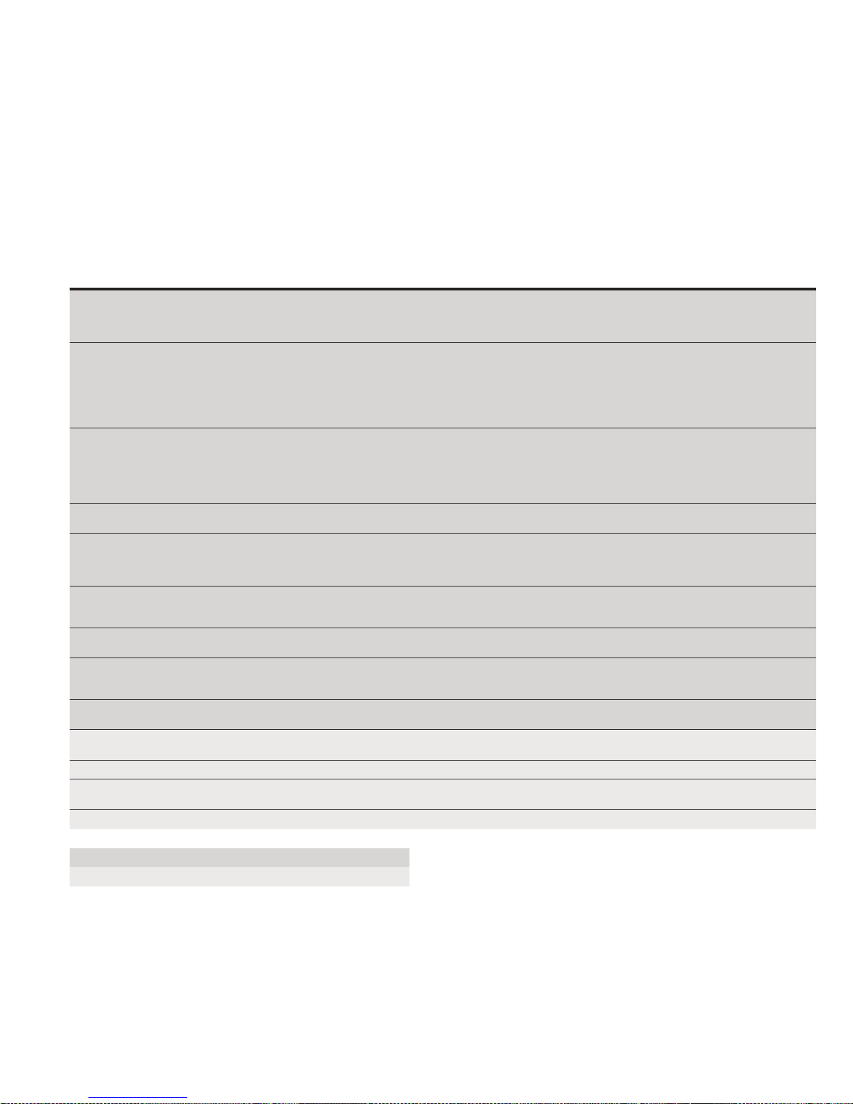
215U-2 802.11
wireless I/O and gateway
User Manual MN032EN
Effective October 2017
Modbus error codes
The following are Modbus error response codes that the Modbus
RTU Master or TCP Client will generate and write to a general
purpose analog register (30501, 40501, and so on) in the event of
a poll fail. Codes 65281 through 65291 (FF01 through FF0B) reflect
Modbus error codes returned from the remote device as codes
01 through 0B. These codes and descriptions are taken from the
Modbus protocol reference. Codes 65024, 64512, 63488 and 65535
(FE00, FC00, F800, and FFFF) are generated by the Modbus master
(Client) on detection of an error with the communications such as a
failure to respond or a garbled message.
Code
(decimal) Hex c ode Name Meaning
65281 FF01 Illegal Function The function code received in the query is not an allowable action for the server (or slave).
65282 FF02 Illegal Data Address The data address received in the query is not an allowable address for the server (or slave).
65283 FF03 Illegal Data Value A value contained in the query data field is not an allowable value for server (or slave). This
65384 FF04 Slave Device Failure An unrecoverable error occurred while the server (or slave) was attempting to perform the
65285 FF05 Acknowledge Specialized use in conjunction with programming commands (Included for completeness).
65286 FF06 Slave Device Busy Specialized use in conjunction with programming commands (Included for completeness). The
65288 FF08 Memory Parity Error Specialized use in conjunction with function codes 20 and 21 and reference type 6, to indicate
65290 FF0A Gateway Path Unavailable Specialized use in conjunction with gateways. Indicates that the gateway was unable to
65291 FF0B Gateway Device Failed to Respond Specialized use in conjunction with gateways. Indicates that no response was obtained from
650 24 FE00 Invalid Response from Slave Command type or slave address did not match request. This error usually indicates that the
64 512 FC00 Server Offline Could not connect to the Modbus TCP ser ver (Applies to Modbus TCP Client only).
63488 F800 Invalid Local Memory Address Local address is invalid in the command. The memory location does not exist or is not
65535 FFFF No Response There was no response to the poll message
This may be because the function code is only applicable to newer devices, and was not
implemented in the unit selected. It might also indicate that the ser ver (or slave) is in the
wrong state to process a request of this type
More specifically, the combination of reference number and transfer length is invalid. For a
controller with 100 registers, the PDU addresses the first register as 0, and the last one as 99.
If a request is submit ted with a starting register address of 96 and a quantity of 4 registers,
this request will successfully operate on registers 96, 97, 98, 99. If a request is submit ted with
a starting register address of 96 and a quantity of 5, this request will fail with Exception Code
0x02 “Illegal Data Address.”
indicates a fault in the structure of the remainder of a complex request. For example, it may
indicate that the implied length is incorrect. It does not mean that a data item submitted
for storage in a register has a value outside the expectation of the application program.
The Modbus protocol is unaware of the significance of any particular value of any particular
register.
requested action
The ser ver (or slave) has accepted the request and is processing it, but significant time will
be required to complete this task. This response is returned to prevent a timeout error from
occurring in the client (or master).
server (or slave) is engaged in processing a long–duration program command. The client (or
master) should retransmit the message later when the server (or slave) is free.
that the extended file area failed to pass a consistency check. (Included for completeness)
allocate an internal communication path from the input port to the output port for processing
the request. Typically indicates that the gateway is mis-configured or overloaded.
the target device. Typically indicates that the device is not present on the network.
response from another request has been received after issuing the current request.
initialized
Error Response from Remote modbus Server (Slave)
Error code generated by local Modbus Client (Master)
EATON www.eaton.com
51
Page 55

User Manual MN032EN
Effective October 2017
Full rmware upgrade
You can upgrade the firmware using a USB flash drive containing the
firmware files. A full USB upgrade is necessary if a patch file is not
available or the existing firmware is a much older version and would
require multiple patch files to upgrade to the latest version.
ote:N The feature keys and configuration are not changed or erased during a
full upgrade.
The following procedure provides instructions for performing a full
USB firmware upgrade on a 215U-2.
Requirements
•
USB flash drive
•
Firmware files (contact ELPRO technical support for these files)
•
PC for transferring files
To prepare the USB flash drive
Not all USB flash drives are configured correctly for use as a
firmware upgrade drive. Use the following procedure to check
the configuration of the USB drive and re-configure the drive if
necessary.
1. Plug USB drive into the USB port on the PC and wait until
Windows recognizes the drive and completes the driver
installation.
2. Open the Windows Start menu, choose Run, and then enter
“CMD” to open a command prompt. Then, type “diskpart” at
the command prompt. This opens the Diskpart utility.
C:\>diskpart
Microsoft DiskPart version 6.1.7601
Copyright (C) 1999-2008 Microsoft
Corporation.
On computer: TEST_COMPUTER
3. Type command “list disk” to list available disks, and identify the
USB drive based on the size.
In the following example, the USB drive is a 1911 MB (2 GB)
drive, which corresponds to Disk 1.
DISKPART> list disk
Disk ### Status Size Free DynGpt
---------------------------------------Disk 0Online232 GB0 B
Disk 1Online 1911 MB0 B
4. When you have identified the USB disk, enter the “select Disk
X” command to select this disk.
WARNING
THE COMMANDS THAT FOLLOW THIS STEP CAN DESTROY THE CONTENTS
OF THE SELECTED DISK, MAKE SURE THAT YOU HAVE SELECTED THE
CORRECT DRIVE BEFORE CONTINUING. SELECTING THE WRONG DRIVE
COULD FORMAT YOUR PC’S HARD DRIVE.
DISKPART> select Disk 1
Disk 1 is now the selected disk.
215U-2 802.11
wireless I/O and gateway
5. Enter the command “list partition” to check how the USB drive
ispartitioned.
This command indicates whether the drive is correctly
configured for use as a firmware upgrade drive on the215U-2.
• If the drive contains only one partition and the “Offset” value is
non-zero, as shown in the example below, you can proceed to
format the drive and use it “as is” for firmware upgrade. Skip
to step 7 for instructions on how to format the drive using the
Diskpart utility.
DISKPART> list partition
Partition ### Type Size Offset
------------ ---- ---- ----- Partition 1Primary 1910 MB 64 KB
• If the “Offset” is zero or if there is more than one partition, as
shown in the examples below, go to steps 6 and 7 below to
re-configure the drive.
Partition ### Type Size Offset
------------ ---- ---- ----- Partition 1Primary 1911 MB 0 KB
Partition ### Type Size Offset
------------ ---- ---- ----- Partition 1Primary 100 MB 64 KB
Partition 2Primary 1810 MB 101 KB
6. Enter the command “clean” to delete all partitions on the disk,
and then enter “list disk” to check that all memory is now free.
In the example below, the asterisk ( * ) indicates that Disk 1 is
the selected disk.
DISKPART> clean
DiskPart succeeded in cleaning the disk.
DISKPART> list disk
Disk ### Status Size Free DynGpt
-------- ------ ---- ------ ----- * Disk 0 Online 1911 MB 1910 KB
7. Enter the command “create partition primary” to create a
partition on the USB drive. Then, enter the “list partition”
command and note that there is only one partition, and that the
offset is non-zero.
DISKPART> create partition primary
DiskPart succeeded in creating the
specified partition
Partition ### Type Size Offset
------------ ---- ---- ----- Partition 1Primary 1910 MB 64 KB
8. Finally, format the drive using the Diskpart command line. The
file system format should be selected as FAT32 using the option
“fs=fat32”. You can select any convenient label. In the example
below the label “FW_UPGRADE” was used.
DISKPART> format fs=fat32 label=FW_
UPGRADE
100 percent completed
DiskPart successfully formatted the
volume.
Alternatively, you can format the drive from within the Windows
GUI environment using the following procedure.
52
EATON www.eaton.com
Page 56
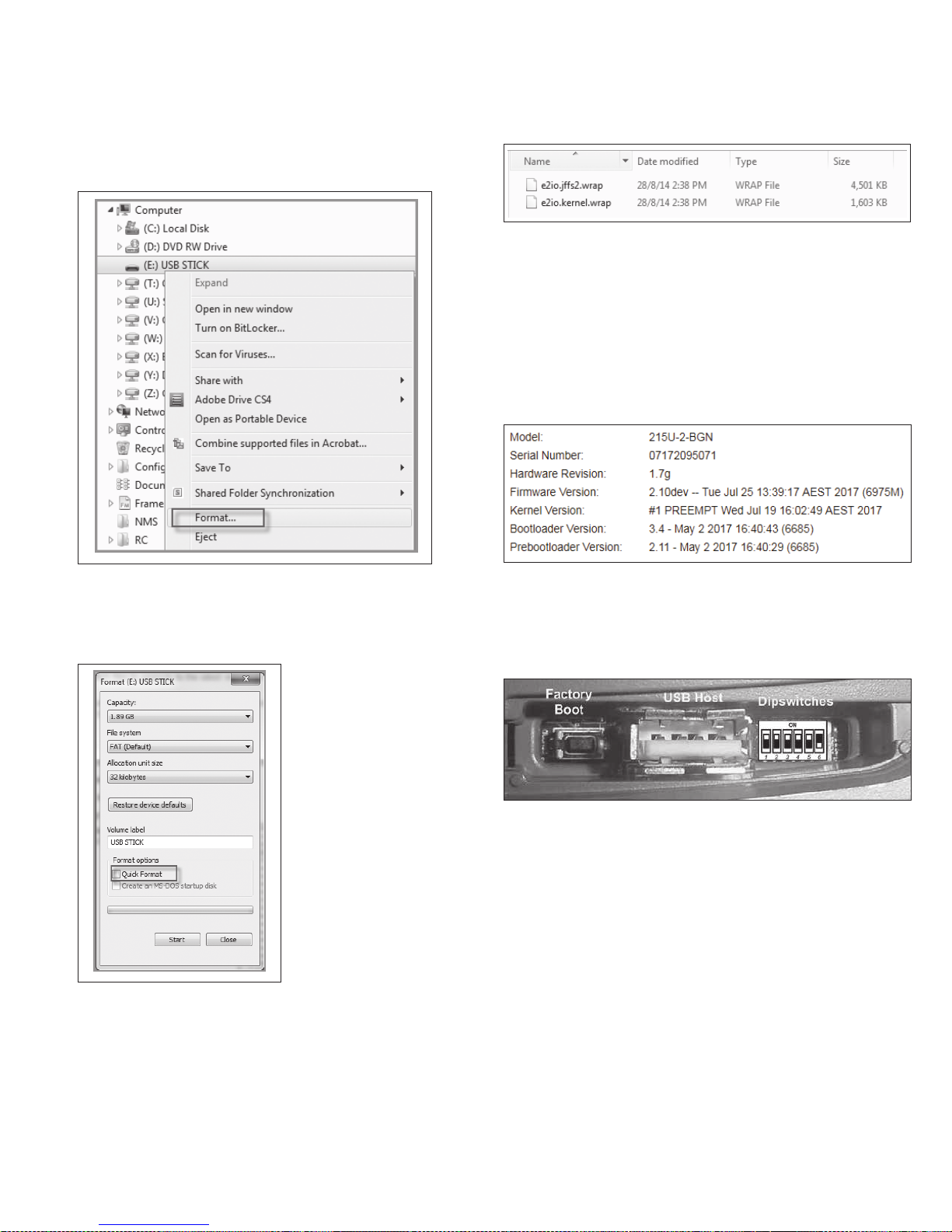
215U-2 802.11
wireless I/O and gateway
User Manual MN032EN
Effective October 2017
To format the USB flash drive
1. Plug the USB flash drive in to the USB port on the PC.
2. Right-click the drive and select Format from the menu.
The files should look similar to the following figure.
Figure 55. Firmware files
5. Remove the USB flash drive from the PC.
To perform a full firmware upgrade using USB flash drive
1. Connect to the module’s Web-based configuration utility and
make a note of the current firmware version, which appears on
the home Web page.
This will enable you to compare versions to confirm that the
upgrade procedure has been performed successfully.
Figure 53. Formatting USB flash drive
3. Make sure that Quick Format is not selected, and then click
Start.
Figure 54. Quick format
Figure 56. Firmware version
2. Power off the 215U-2if it is currently powered on.
3. Remove the cover from the small access panel on side of
module to reveal a USB port and switches.
Figure 57. Module USB port and switches
4. Plug USB stick into USB port and power on the 215U-2 module.
5. The PWR LED will flash, as indicated in [Figure 58 below].
ote:N Do not remove the flash drive or interrupt power to the module while
the upgrade is in progress. If the upgrade process is interrupted, the module
may become unserviceable and will need to be returned to Eaton for repair.
4. When formatting is complete, copy the supplied firmware files to
the USB flash drive root directory.
EATON www.eaton.com
53
Page 57
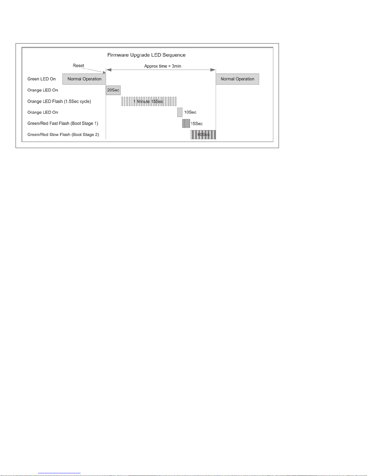
User Manual MN032EN
Effective October 2017
Figure 58. Firmware upgrade LED indicators
6. When the upgrade is complete, remove the USB flash drive from
the module’s USB port and replace the access panel cover.
215U-2 802.11
wireless I/O and gateway
54
EATON www.eaton.com
Page 58

215U-2 802.11
wireless I/O and gateway
GNU free document license
Version 2, June 1991
Copyright (C) 1989, 1991 Free Software Foundation, Inc.
51 Franklin Street, Fifth Floor, Boston, MA 02110-1301, USA
Everyone is permitted to copy and distribute verbatim copies of this
license document, but changing it is not allowed.
Preamble
The licenses for most software are designed to take away your
freedom to share and change it. By contrast, the GNU General Public
License is intended to guarantee your freedom to share and change
free software--to make sure the software is free for all its users.
This General Public License applies to most of the Free Software
Foundation’s software and to any other program whose authors
commit to using it. (Some other Free Software Foundation software
is covered by the GNU Lesser General Public License instead.) You
can apply it to your programs, too.
When we speak of free software, we are referring to freedom, not
price. Our General Public Licenses are designed to make sure that
you have the freedom to distribute copies of free software (and
charge for this service if you wish), that you receive source code or
can get it if you want it, that you can change the software or use
pieces of it in new free programs; and that you know you can do
these things.
To protect your rights, we need to make restrictions that forbid
anyone to deny you these rights or to ask you to surrender the
rights. These restrictions translate to certain responsibilities for you if
you distribute copies of the software, or if you modify it.
For example, if you distribute copies of such a program, whether
gratis or for a fee, you must give the recipients all the rights that
you have. You must make sure that they, too, receive or can get the
source code. And you must show them these terms so they know
their rights.
We protect your rights with two steps: (1) copyright the software,
and (2) offer you this license which gives you legal permission to
copy, distribute and/or modify the software.
Also, for each author’s protection and ours, we want to make certain
that everyone understands that there is no warranty for this free
software. If the software is modified by someone else and passed
on, we want its recipients to know that what they have is not the
original, so that any problems introduced by others will not reflect on
the original authors’ reputations.
Finally, any free program is threatened constantly by software
patents. We wish to avoid the danger that redistributors of a free
program will individually obtain patent licenses, in effect making
the program proprietary. To prevent this, we have made it clear that
any patent must be licensed for everyone’s free use or not licensed
at all.
The precise terms and conditions for copying, distribution and
modification follow.
Terms And Conditions For Copying, Distribution And
Modification
This License applies to any program or other work which contains
a notice placed by the copyright holder saying it may be distributed
under the terms of this General Public License. The “Program”,
below, refers to any such program or work, and a “work based on
the Program” means either the Program or any derivative work
under copyright law: that is to say, a work containing the Program or
a portion of it, either verbatim or with modifications and/or translated
into another language. (Hereinafter, translation is included without
limitation in the term “modification”.) Each licensee is addressed as
“you”.
User Manual MN032EN
Effective October 2017
Activities other than copying, distribution and modification are
not covered by this License; they are outside its scope. The act
of running the Program is not restricted, and the output from the
Program is covered only if its contents constitute a work based
on the Program (independent of having been made by running the
Program). Whether that is true depends on what the Program does.
1. You may copy and distribute verbatim copies of the Program’s
source code as you receive it, in any medium, provided that
you conspicuously and appropriately publish on each copy an
appropriate copyright notice and disclaimer of warranty; keep
intact all the notices that refer to this License and to the absence
of any warranty; and give any other recipients of the Program a
copy of this License along with the Program.
You may charge a fee for the physical act of transferring a copy,
and you may at your option offer warranty protection in exchange
for a fee.
2. You may modify your copy or copies of the Program or any
portion of it, thus forming a work based on the Program, and
copy and distribute such modifications or work under the terms
of Section 1 above, provided that you also meet all of these
conditions:
a. You must cause the modified files to carry prominent notices
stating that you changed the files and the date of any
change.
b. You must cause any work that you distribute or publish, that
in whole or in part contains or is derived from the Program or
any part thereof, to be licensed as a whole at no charge to all
third parties under the terms of this License.
c. If the modified program normally reads commands
interactively when run, you must cause it, when started
running for such interactive use in the most ordinary way, to
print or display an announcement including an appropriate
copyright notice and a notice that there is no warranty (or
else, saying that you provide a warranty) and that users may
redistribute the program under these conditions, and telling
the user how to view a copy of this License. (Exception: if
the Program itself is interactive but does not normally print
such an announcement, your work based on the Program is
not required to print an announcement.)
These requirements apply to the modified work as a whole.
If identifiable sections of that work are not derived from the
Program and can be reasonably considered independent and
separate works in themselves, then this License, and its
terms, do not apply to those sections when you distribute
them as separate works. But when you distribute the same
sections as part of a whole which is a work based on the
Program, the distribution of the whole must be on the terms
of this License, whose permissions for other licensees
extend to the entire whole, and thus to each and every part
regardless of who wrote it.
Thus, it is not the intent of this section to claim rights or
contest your rights to work written entirely by you; rather,
the intent is to exercise the right to control the distribution
of derivative or collective works based on the Program.
In addition, mere aggregation of another work not based
on the Program with the Program (or with a work based
on the Program) on a volume of a storage or distribution
medium does not bring the other work under the scope of
this License.
EATON www.eaton.com
55
Page 59

User Manual MN032EN
Effective October 2017
215U-2 802.11
wireless I/O and gateway
3. You may copy and distribute the Program (or a work based on
it, under Section 2) in object code or executable form under the
terms of Sections 1 and 2 above provided that you also do one
of the following:
a. Accompany it with the complete corresponding machine-
readable source code, which must be distributed under the
terms of Sections 1 and 2 above on a medium customarily
used for software interchange; or,
b. Accompany it with a written offer, valid for at least three
years, to give any third party, for a charge no more than your
cost of physically performing source distribution, a complete
machine-readable copy of the corresponding source code, to
be distributed under the terms of Sections 1 and 2 above on
a medium customarily used for software interchange; or,
c. Accompany it with the information you received as to
the offer to distribute corresponding source code. (This
alternative is allowed only for noncommercial distribution and
only if you received the program in object code or executable
form with such an offer, in accord with Subsection b above.)
The source code for a work means the preferred form of
the work for making modifications to it. For an executable
work, complete source code means all the source code
for all modules it contains, plus any associated interface
definition files, plus the scripts used to control compilation
and installation of the executable. However, as a special
exception, the source code distributed need not include
anything that is normally distributed (in either source or
binary form) with the major components (compiler, kernel,
and so on) of the operating system on which the executable
runs, unless that component itself accompanies the
executable.
If distribution of executable or object code is made by
offering access to copy from a designated place, then
offering equivalent access to copy the source code from the
same place counts as distribution of the source code, even
though third parties are not compelled to copy the source
along with the object code.
4. You may not copy, modify, sublicense, or distribute the Program
except as expressly provided under this License. Any attempt
otherwise to copy, modify, sublicense or distribute the Program
is void, and will automatically terminate your rights under
this License. However, parties who have received copies, or
rights, from you under this License will not have their licenses
terminated so long as such parties remain in full compliance.
5. You are not required to accept this License, since you have not
signed it. However, nothing else grants you permission to modify
or distribute the Program or its derivative works. These actions
are prohibited by law if you do not accept this License. Therefore,
by modifying or distributing the Program (or any work based on
the Program), you indicate your acceptance of this License to do
so, and all its terms and conditions for copying, distributing or
modifying the Program or works based on it.
6. Each time you redistribute the Program (or any work based on
the Program), the recipient automatically receives a license from
the original licensor to copy, distribute or modify the Program
subject to these terms and conditions. You may not impose
any further restrictions on the recipients’ exercise of the rights
granted herein. You are not responsible for enforcing compliance
by third parties to this License.
7. If, as a consequence of a court judgment or allegation of patent
infringement or for any other reason (not limited to patent
issues), conditions are imposed on you (whether by court order,
agreement or otherwise) that contradict the conditions of this
License, they do not excuse you from the conditions of this
License. If you cannot distribute so as to satisfy simultaneously
your obligations under this License and any other pertinent
obligations, then as a consequence you may not distribute
the Program at all. For example, if a patent license would not
permit royalty-free redistribution of the Program by all those who
receive copies directly or indirectly through you, then the only
way you could satisfy both it and this License would be to refrain
entirely from distribution of the Program.
If any portion of this section is held invalid or unenforceable
under any particular circumstance, the balance of the section is
intended to apply and the section as a whole is intended to apply
in other circumstances.
It is not the purpose of this section to induce you to infringe any
patents or other property right claims or to contest validity of
any such claims; this section has the sole purpose of protecting
the integrity of the free software distribution system, which
is implemented by public license practices. Many people have
made generous contributions to the wide range of software
distributed through that system in reliance on consistent
application of that system; it is up to the author/donor to decide
if he or she is willing to distribute software through any other
system and a licensee cannot impose that choice.
This section is intended to make thoroughly clear what is
believed to be a consequence of the rest of this License.
8. If the distribution and/or use of the Program is restricted in
certain countries either by patents or by copyrighted interfaces,
the original copyright holder who places the Program under this
License may add an explicit geographical distribution limitation
excluding those countries, so that distribution is permitted only
in or among countries not thus excluded. In such case, this
License incorporates the limitation as if written in the body of
this License.
9. The Free Software Foundation may publish revised and/or new
versions of the General Public License from time to time. Such
new versions will be similar in spirit to the present version, but
may differ in detail to address new problems or concerns.
Each version is given a distinguishing version number. If the
Program specifies a version number of this License which
applies to it and “any later version”, you have the option of
following the terms and conditions either of that version or of
any later version published by the Free Software Foundation. If
the Program does not specify a version number of this License,
you may choose any version ever published by the Free Software
Foundation.
10. If you wish to incorporate parts of the Program into other free
programs whose distribution conditions are different, write to the
author to ask for permission. For software which is copyrighted
by the Free Software Foundation, write to the Free Software
Foundation; we sometimes make exceptions for this. Our
decision will be guided by the two goals of preserving the free
status of all derivatives of our free software and of promoting the
sharing and reuse of software generally.
56
EATON www.eaton.com
Page 60

215U-2 802.11
wireless I/O and gateway
NO WARRANTY
11. BECAUSE THE PROGRAM IS LICENSED FREE OF CHARGE,
THERE IS NO WARRANTY FOR THE PROGRAM, TO THE
EXTENT PERMITTED BY APPLICABLE LAW. EXCEPT WHEN
OTHERWISE STATED IN WRITING THE COPYRIGHT HOLDERS
AND/OR OTHER PARTIES PROVIDE THE PROGRAM “AS IS”
WITHOUT WARRANTY OF ANY KIND, EITHER EXPRESSED OR
IMPLIED, INCLUDING, BUT NOT LIMITED TO, THE IMPLIED
WARRANTIES OF MERCHANTABILITY AND FITNESS FOR A
PARTICULAR PURPOSE. THE ENTIRE RISK AS TO THE QUALITY
AND PERFORMANCE OF THE PROGRAM IS WITH YOU.
SHOULD THE PROGRAM PROVE DEFECTIVE, YOU ASSUME
THE COST OF ALL NECESSARY SERVICING, REPAIR OR
CORRECTION.
12. IN NO EVENT UNLESS REQUIRED BY APPLICABLE LAW OR
AGREED TO IN WRITING WILL ANY COPYRIGHT HOLDER,
OR ANY OTHER PARTY WHO MAY MODIFY AND/OR
REDISTRIBUTE THE PROGRAM AS PERMITTED ABOVE, BE
LIABLE TO YOU FOR DAMAGES, INCLUDING ANY GENERAL,
SPECIAL, INCIDENTAL OR CONSEQUENTIAL DAMAGES
ARISING OUT OF THE USE OR INABILITY TO USE THE
PROGRAM (INCLUDING BUT NOT LIMITED TO LOSS OF
DATA OR DATA BEING RENDERED INACCURATE OR LOSSES
SUSTAINED BY YOU OR THIRD PARTIES OR A FAILURE OF THE
PROGRAM TO OPERATE WITH ANY OTHER PROGRAMS), EVEN
IF SUCH HOLDER OR OTHER PARTY HAS BEEN ADVISED OF
THE POSSIBILITY OF SUCH DAMAGES.
User Manual MN032EN
Effective October 2017
EATON www.eaton.com
57
Page 61

User Manual MN032EN
Effective October 2017
Glossary
Ter m Definition
802.11 A standards for
wirel ess net workin g
allowing high speed wir eless
connection b etwee n devices.
ACK
Acces s Point
Antenna Gain
AWG
Bandwidth
COS
CSA
DCS
DHCP
DIO
DIN Rail
DNS
Encryption Key
EIRP
Hub
Hz
IEEE
I/O
IP
IP Address
ISM
LAN
LQI
Receive Sensitivity
Router
Acknowledgment.
An access point connects wireless network stations (or clients) to other stations within the wireless network and also can serve as
the point of interconnection between the wireless network and a wired network. Each access point can serve multiple users within a
defined network area. Also known as a base station.
Antennas do not increase the transmission power, but instead focus the signal. Rather than transmitting in every direction (including
the sky and ground), antenna focus the signal either more horizontally or in one particular direction. This gain is measured in decibels.
American wire gauge (AWG), also known as the Brown and Sharpe wire gauge, is a standardized wire gauge system used
predominantly in the United States and Canada for the
diameters of round, solid, nonferrous, electrically conducting wire.
The maximum data transfer speed available to a user through a net work.
Change of state. For a digital input, a COS is a change from “off” to “on,” or a change from “on” to “off.” For an analog input, internal
analog input, or pulse input rate, a COS is a configurable value called sensitivity.
The Canadian Standards Association (CSA), is a not-for-profit standards organization that develops standards in 57 areas. The
CSA registered mark shows that a product has been independently tested and certified to meet recognized standards for safety or
performance.
A Distributed Control System (DCS) is a computerized control system used to control the production line in industry. The entire system
of controllers is connected by networks for communication and monitoring.
Dynamic Host Configuration Protocol is a utility that enables a server to dynamically assign IP addresses from a predefined list and limit
their time of use so that they can be reassigned. Without DHCP, an IT manager would need to manually enter in all the IP addresses
of all the computers on the network. When DHCP is used, whenever a computer logs onto the network, an IP address is automatically
assigned to it.
Digital input/output.
A DIN rail is a metal rail of a standard type widely used for mounting circuit breakers and industrial control equipment inside equipment
racks.
Domain name service (DNS) is a program that translates URLs to IP addresses by accessing a database maintained on a collection
of Internet servers. The program works behind the scenes to facilitate surfing the Web with alpha versus numeric addresses. A DNS
server conver ts a name like mywebsite.com to a series of numbers like 107.22.55.26. Every website has its own specific IP address on
the Internet.
An alphanumeric (let ters and/or numbers) series that enables data to be encrypted and then decrypted so it can be safely shared
among members of a network. WEP uses an encryption key that automatically encrypts outgoing wireless data. On the receiving side,
the same encryption key enables the computer to automatically decr ypt the information so it can be read. Encryption keys should be
kept secret.
Equivalent isotropically radiated power (EIRP) or, alternatively, effective isotropically radiated power is the amount of power that a
theoretical isotropic antenna (which evenly distributes power in all directions) would emit to produce the peak power density observed
in the direction of maximum antenna gain. EIRP can take into account the losses in transmission line and connectors and includes the
gain of the antenna. The EIRP is of ten stated in terms of decibels over a reference power emitted by an isotropic radiator with an
equivalent signal strength. The EIRP allows comparisons bet ween dif ferent emitters regardless of type, size or form.
A multiport device used to connect PCs to a network via Ethernet cabling. Wired hubs can have numerous ports and can transmit data
at speeds ranging from 10 Mbps to multi-Gigabyte speeds per second. A hub transmits packets it receives to all the connected ports. A
small wired hub may only connect four computers; a large hub can connect 48 or more.
Hert z. The international unit for measuring frequency, equivalent to the older unit of cycles per second. One megaher tz (MHz) is one
million hertz. One gigahertz (GHz) is one billion hertz. The standard US electrical power frequency is 60 Hz, the AM broadcast radio
frequency band is 535–1605kHz, the FM broadcast radio frequency band is 88–108 MHz, and wireless 802.11b/g LANs operate at 2.4
GHz.
Institute of Electrical and Electronics Engineers, New York, www.ieee.org. A membership organization that includes engineers,
scientists and students in electronics and allied fields. It has more than 300,000 members and is involved with setting standards for
computers and communications.
Input/Output. The term used to describe any operation, program, or device that transfers data to or from a computer.
Internet Protocol (IP) is a set of rules used to send and receive messages across local networks and the Internet.
A 32-bit number that identifies each sender or receiver of information that is sent across the Internet. An IP address has two parts:
an identifier of a particular network on the Internet and an identifier of the particular device (which can be a server or a workstation)
within that network.
The industrial, scientific and medical (ISM) radio bands are portions of the radio spectrum reserved internationally for industrial,
scientific, and medical purposes other than telecommunications.
Local Area Network (L AN) is a system of connecting PCs and other devices within the same physical proximity for sharing resources
such as an Internet connections, printers, files, and drives.
Link qualit y indicator (LQI) is used in wireless networks to indicate how strong the communications link is. LQI is a computed value,
based on the received signal strength as well as the number of errors received.
The minimum signal strength required to pick up a signal. Higher bandwidth connections usually have less receive sensitivit y than lower
bandwidth connections.
A device that forwards data from one WLAN or wired local area network to another.
215U-2 802.11
wireless I/O and gateway
58
EATON www.eaton.com
Page 62

215U-2 802.11
wireless I/O and gateway
Ter m Definition
RSSI
Transmit Power
MAC Address
Modbus
PLC
Proxy Server
RJ-45
RTU
SCADA
Server
SMA
Sub Network orSubnet
Switch
TCP
TCP/IP
TTL
WAN
Wi-Fi
Received signal strength indicator (RSSI) is a measurement of the power present in a received radio signal. In an IEEE 802.11 system,
RSSI is the relative received signal strength in a wireless environment, in arbitrary units. RSSI is an indication of the power level being
received by the antenna. Therefore, the higher the RSSI number (or less negative in some devices), the stronger the signal.
The power at which the wireless devices transmits, usually expressed in mW or dBm.
Media Access Control (MAC) address is a unique code assigned to most forms of networking hardware. T he address is permanently
assigned to the hardware, so limiting a wireless network’s access to hardware (such as wireless cards) is a security feature employed
by closed wireless networks. But an experienced hacker armed with the proper tools can still figure out an authorized MAC address,
masquerade as a legitimate address, and access a closed network.
Every wireless 802.11 device has its own specific MAC address hard-coded into it. This unique identifier can be used to provide
security for wireless net works. When a net work uses a MAC table, only the 802.11 radios that have had their MAC addresses added to
that network’s MAC table will be able to get onto the network.
Modbus is a serial communications protocol for use with its programmable logic controllers (PLCs).
A programmable logic controller (PLC) is a digital computer used for automation of electromechanical processes, such as control of
machiner y on factory assembly lines, amusement rides, or light fixtures.
Used in larger companies and organizations to improve network operations and security, a proxy server is able to prevent direct
communication between t wo or more networks. The proxy server for wards allowable data requests to remote servers and/or responds
to data requests directly from stored remote server data.
Standard connectors used in Ethernet networks. RJ-45 connectors are similar to standard RJ-11 telephone connectors, but RJ-45
connectors can have up to eight wires, whereas telephone connectors have four.
A remote terminal unit (RTU) is a microprocessor-controlled electronic device that interfaces objects in the physical world to a
distributed control system or SCADA system by transmitting telemetr y data to a master system, and by using messages from the
master supervisory system to control connected objects.
SCADA (supervisory control and data acquisition) is a type of industrial control system (ICS). Industrial control systems are computer
controlled systems that monitor and control industrial processes that exist in the physical world. SCADA systems historically
distinguish themselves from other ICS systems by being large scale processes that can include multiple sites, and large distances.
A computer that provides its resources to other computers and devices on a network. These include print servers, Internet servers and
data servers. A server can also be combined with a hub or router.
SMA (SubMiniature version A) connectors are semi-precision coaxial RF connectors for coaxial cable with a screw type coupling
mechanism. The connector has a 50 Ω impedance. It is designed for use from DC to 18 GHz.
Found in larger networks, these smaller networks are used to simplify addressing between numerous computers. Subnets connect
together through a router.
A type of hub that efficiently controls the way multiple devices use the same network so that each can operate at optimal performance.
A switch acts as a networks traffic cop: rather than transmit ting all the packets it receives to all ports as a hub does, a switch
transmits packets to only the receiving port.
Transmission Control Protocol (TCP) isprotocol used along with the Internet Protocol (IP) to send data in the form of individual units
(called packets) bet ween computers over the Internet. While IP takes care of handling the actual deliver y of the data, TCP takes care
of keeping track of the packets that a message is divided into for efficient routing through the Internet. For example, when a Web
page is downloaded from a Web ser ver, the TCP program layer in that server divides the file into packets, numbers the packets, and
then forwards them individually to the IP program layer. Although each packet has the same destination IP address, it may get routed
differently through the network. At the other end, TCP reassembles the individual packets and waits until they have all arrived to
forward them as single message.
The underlying technology behind the Internet and communications between computers in a network. The first part, TCP, is the
transport part, which matches the size of the messages on either end and guarantees that the correct message has been received.
The IP part is the user’s computer address on a network. Every computer in a TCP/IP network has its own IP address that is either
dynamically assigned at star tup or permanently assigned. All TCP/IP messages contain the address of the destination net work as well
as the address of the destination station. This enables TCP/IP messages to be transmitted to multiple networks (subnets) within an
organization or worldwide.
Transistor–transistor logic (TTL) is a class of digital circuits built from bipolar junction transistors and resistors. It is called TTL logic
because both the logic gating function (AND) and the amplifying function are performed by transistors.
Wide area network (WAN) is a communication system of connecting PCs and other computing devices across a large local, regional,
national or international geographic area. Also used to distinguish between phone-based data networks and Wi-Fi. Phone net works are
considered WANs and Wi-Fi networks are considered Wireless Local Area Net works (WLANs).
Wireless Fidelity. An interoperability certification for wireless local area network (LAN) products based on the Institute of Electrical
and Electronics Engineers (IEEE) 802.11 standard.
User Manual MN032EN
Effective October 2017
EATON www.eaton.com
59
Page 63

Eaton
1000 Eaton Boulevard
Cleveland, OH 44122
United States
Eaton.com
© 2017 Eaton
All Rights Reserved
Printed in USA
Publication No. MN032EN / CSSC-1703-4112
October 2017
Eaton is a registered trademark.
All other trademarks are property
of their respective owners.
 Loading...